JP5116728B2 - Traffic information processing system - Google Patents
Traffic information processing system Download PDFInfo
- Publication number
- JP5116728B2 JP5116728B2 JP2009137080A JP2009137080A JP5116728B2 JP 5116728 B2 JP5116728 B2 JP 5116728B2 JP 2009137080 A JP2009137080 A JP 2009137080A JP 2009137080 A JP2009137080 A JP 2009137080A JP 5116728 B2 JP5116728 B2 JP 5116728B2
- Authority
- JP
- Japan
- Prior art keywords
- information
- road
- vehicle
- management target
- processing system
- Prior art date
- Legal status (The legal status is an assumption and is not a legal conclusion. Google has not performed a legal analysis and makes no representation as to the accuracy of the status listed.)
- Expired - Fee Related
Links
Images






Landscapes
- Instructional Devices (AREA)
- Navigation (AREA)
Description
本発明は、管理対象道路を走行する車両の交通情報を処理する交通情報処理システムに関する。 The present invention relates to a transportation information processing system that handles traffic information of vehicles traveling managed road.
従来、道路上の交通に関する情報をユーザに提供する代表的なシステムとして、道路交通情報通信システム(Vehicle Information and Communication System;以下VICSと記す)があり、渋滞情報、目的地への所要時間、事故・故障車・工事情報のような様々な交通情報が提供されている。VICSによる交通情報を入手するためには、VICS対応の車載器、例えばナビゲーションシステムを搭載する必要があり、高速道路や幹線道路の路側に設置されたビーコンから発射された電磁波等を受信することで、自車両の位置情報や渋滞情報等をナビゲーションシステムの画面に表示することができる。 Conventionally, as a typical system for providing information on traffic on a road to a user, there is a road traffic information communication system (hereinafter referred to as VICS), which includes traffic jam information, time required for a destination, and an accident.・ Various traffic information such as broken cars and construction information is provided. In order to obtain traffic information by VICS, it is necessary to install a VICS compatible vehicle-mounted device, for example, a navigation system, and by receiving electromagnetic waves emitted from beacons installed on the roadside of highways and main roads In addition, the position information of the own vehicle, traffic jam information, and the like can be displayed on the screen of the navigation system.
また、ナビゲーションシステムのような車載器においては、全地球測位システム(Global Positioning System;以下GPSと記す)による自車位置の緯度経度情報と、VICSにより標準化された地図情報、すなわち「道路リンク」と呼ばれる交差点等で区切られた道路範囲を区域区画単位(メッシュ)とした地図情報を対応させ(マップマッチング)、自車両の位置特定や走行経路の算定を行っている。これにより、全国の道路地図情報をデジタルコードとして標準化された体系に組み込み、地図の共有化及び製品の標準化を図っている。 In addition, in a vehicle-mounted device such as a navigation system, latitude and longitude information of the vehicle position by a global positioning system (hereinafter referred to as GPS) and map information standardized by VICS, that is, “road link” Map information with the road range demarcated at intersections, etc., called area division units (mesh) associating with each other (map matching) is used to specify the position of the host vehicle and to calculate the travel route. In this way, the road map information of the whole country is incorporated into a standardized system as a digital code, and the sharing of the map and the standardization of the product are attempted.
従来システムの例として、例えば特許文献1では、メッシュ形状の区域区画単位に分割された電子地図において、この各々のメッシュに道路リンクのコードを付与し、地図上の経路探索等に活用した旅行時間算出システムが提示されている。一方、特許文献2では、標準の道路リンクを使用せず、独自の道路形状データを適用したデジタル地図の位置情報伝達方法が提示されている。
As an example of a conventional system, for example, in
特許文献1に示されている旅行時間算出システムのように、従来の「道路リンク」を使用することを前提としてシステム構築を行うには、その全データを有していなければならないという問題があった。また、「道路リンク」は、全国の道路を網羅するものであるから、管轄道路が限定された地域であっても全国網を前提とした位置検索が行われ、個々の車両位置を特定する計算の都度、システムに高い計算処理性能が要求される。このため、例えば高速道路のような車両走行量の膨大な道路上での迅速な交通情報処理の手法としては適切ではなかった。
As in the travel time calculation system disclosed in
また、「道路リンク」は、標準化された地図データコードであるため、例えば道路事業者であるユーザが道路図面を独自に追加することは容易ではない。このため、道路事業者が「道路リンク」を使用して道路交通情報システムを自社構築した場合には、新設道路の道路リンクコードがタイムリーに更新されなければシステムの運用に不都合が生じるという問題があった。このように、「道路リンク」を使用することを前提としたシステム構築は、特定の地理的範囲の道路を管轄する事業者(例えば高速道路の道路管理者)、及びその利用者等の需要の実態に応えるものではなかった。 Further, since the “road link” is a standardized map data code, it is not easy for a user who is a road operator to add a road drawing independently. For this reason, when a road operator builds a road traffic information system using “road links”, the system operation will be inconvenient if the road link code of the new road is not updated in a timely manner. was there. As described above, the system construction based on the use of “road links” is based on the demands of the operators (for example, highway road managers) who have jurisdiction over the roads in a specific geographical area and their users. It did not respond to the actual situation.
一方、特許文献2に示されたような、従来の「道路リンク」を使用せずに独自の道路形状データを適用する方法では、地図上に緯度経度情報を当てはめる際に複雑な処理を必要とすることや、道路形状に合わせた区域区画単位の形状を都度定義する必要があることから、処理が大変煩雑であり、具体的な手法も確立されていなかった。
On the other hand, in the method of applying original road shape data without using the conventional “road link” as shown in
本発明は、上記のような問題点を解消するためになされたもので、管理対象道路を走行する車両の車両位置を特定するための計算処理を単純化し、計算機負荷を低減させることが可能な交通情報処理システムを提供することを目的とする。 The present invention has been made to solve the above-described problems, and can simplify calculation processing for specifying the vehicle position of a vehicle traveling on a management target road and reduce the computer load. an object of the present invention is to provide a traffic information processing Rishi system.
本発明に係る交通情報処理システムは、道路地図上において管理対象道路に対して車両の走行方向に複数の基点N 1 、N 2 、N 3 ・・を互いに間隔を置いて配置し、各基点に対応して設定された矩形区画S 1 、S 2 、S 3 ・・を管理対象道路に割り付け、管理対象道路を区画割りするとともに、矩形区画の集合からなる評価管理区域の座標を定義する評価管理区域設定手段と、各矩形区画を走行する車両から収集された緯度経度情報及び時刻情報を含む走行履歴情報を取得する走行履歴情報取得手段と、走行履歴情報取得手段により取得した走行履歴情報が正常な情報であるか否かを車両ごとに判断し、正常な走行履歴情報を抽出する正常情報抽出手段と、正常情報抽出手段により正常と判断された走行履歴情報をもとに、各矩形区画を走行した車両の速度情報を算出し、さらに前記速度情報をもとにした統計処理により管理対象道路を走行した車両に関する交通情報を求める統計処理手段を備え、評価管理区域設定手段は、管理対象道路の区画割りにおいて、複数の基点を管理対象道路の略中央を示す線上に任意の間隔で配置し、矩形区画を形成する4つの線分のうちの2つの線分を、隣り合う2つの基点を結んだ線分と略平行に配置すると共に、隣り合う2つの基点を結んだ線分と略垂直な2つの線分の長さを、管理対象道路の幅と、その幅の両外側に全地球測位システム(GPS)の測位誤差を足したものとし、管理対象道路のカーブ部においては、n番目の矩形区画S n を、n番目の基点N n の(n+1)番目の基点N (n+1) に対する仰角θ n 分だけ回転させて割り付けるものである。 In the traffic information processing system according to the present invention, a plurality of base points N 1 , N 2 , N 3 ... Are arranged at intervals from each other in the vehicle traveling direction with respect to a management target road on a road map. Evaluation management that assigns the rectangular sections S 1 , S 2 , S 3 ... Set corresponding to the management target roads, divides the management target roads, and defines the coordinates of the evaluation management area composed of a set of rectangular sections The travel history information acquired by the zone setting means, the travel history information acquiring means for acquiring the travel history information including the latitude and longitude information and the time information collected from the vehicle traveling in each rectangular section, and the travel history information acquired by the travel history information acquiring means are normal. Each of the rectangular sections based on the normal information extracting means for extracting normal driving history information and the driving history information determined to be normal by the normal information extracting means. It calculates the traveling speed information of the vehicle, further comprising a statistical processing unit for obtaining the traffic information about the vehicle traveling on the managed roads by a statistical process based on the speed information, evaluation management area setting means, managed In road division, multiple base points are arranged on the line indicating the approximate center of the road to be managed at arbitrary intervals, and two of the four line segments that form a rectangular block are replaced by two adjacent base points. And the length of two line segments that are approximately perpendicular to the line segment that connects two adjacent base points, and the width of the road to be managed, global positioning system and plus the positioning error of the (GPS), in the curve of the managed roads, the n-th rectangular compartments S n, the n-th base point n n (n + 1) th base point n (n + 1) It is rotated by the elevation angle theta n min for It is intended to be assigned.
本発明によれば、管理対象道路上の各基点に対応した矩形区画を設定し、この矩形区画により管理対象道路を区画割りするとともに、矩形区画の集合からなる評価管理区域の座標を定義するようにしたので、各矩形区画を走行する車両から取得した走行履歴情報をもとに当該車両の車両位置を容易に高い精度で特定することができ、また、位置特定のための計算処理を単純化し計算機負荷を低減させることができるため、大容量の交通量負荷へ
の円滑な処理対応が可能である。
According to the present invention, a rectangular section corresponding to each base point on the management target road is set, the management target road is divided by the rectangular section, and the coordinates of the evaluation management area composed of a set of rectangular sections are defined. As a result, the vehicle position of the vehicle can be easily identified with high accuracy based on the travel history information acquired from the vehicle traveling in each rectangular section, and the calculation processing for position identification is simplified. Since the computer load can be reduced, it is possible to cope with a large amount of traffic load smoothly.
実施の形態1.
以下に、本発明の実施の形態1に係る交通情報処理システムについて、図面に基づいて説明する。本実施の形態1に係る交通情報処理システムは、管理対象道路を走行する車両に搭載された車載器に記録された走行履歴情報を、DSRC(狭帯域通信)等を利用した送受信機により受信し、これをもとに管理対象道路を走行する車両の走行状態を判別し、渋滞情報、目的地への所要時間のような様々な交通情報をユーザに提供するものである。
Below, the traffic information processing
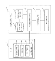
図1は、本実施の形態1に係る交通情報処理システムの構成を示す概略図である。本実施の形態1における交通情報処理システム1は、主に、管理対象の道路地図を含む地図情報が格納された地図情報データベース2と、管理対象道路を含む評価管理区域を設定する評価管理区域設定手段3と、評価管理区域を走行する車両7から走行履歴情報8を取得する走行履歴情報取得手段4と、正常な走行履歴情報8を抽出する正常情報抽出手段5と、正常な走行履歴情報8をもとに評価管理区域を走行する車両7の速度情報を算出し、さらに速度情報をもとにした統計処理により、管理対象道路9を走行した車両7に関する交通情報を求める統計処理手段6から構成される。
FIG. 1 is a schematic diagram showing the configuration of the traffic information processing system according to the first embodiment. The traffic
また、車両7に搭載された車載器から伝送される走行履歴情報8には、車両7の現在位置を示す緯度経度情報81と時刻情報82が含まれ、これらの情報から当該車両の速度ベクトルを算出することができる。なお、フラグ情報83は、車両7が管理対象道路9を走行していることを示す判断情報であり、必要に応じて走行履歴情報8に付与される。この
フラグ情報83については、後述の実施の形態4で説明する。
The
評価管理区域設定手段3は、地図情報データベース2に格納された道路地図上において管理対象道路を含む評価管理区域を設定するものである。評価管理区域設定手段3による評価管理区域の設定方法について、図2〜図4を用いて説明する。まず、図2に示すように、管理対象道路9に対して、図中矢印で示す車両の走行方向11に、複数の基点N1、N2、N3・・を互いに間隔を置いて配置する。本実施の形態1では、複数の基点N1、N2、N3・・は、管理対象道路9の中央を示す線10上に所定間隔Aで配置されている。なお、各基点の間隔は一定でなくても良く、任意の間隔で配置することができる。
The evaluation management area setting means 3 sets an evaluation management area including a management target road on the road map stored in the
このように、管理対象道路9の中央を示す線10上に定義した基点N1、N2、N3・・を連続的に線分で結ぶことで、道路線形に沿った位置情報を表すことができる。このような基点を一般に道路リンクと言い、通常、所定間隔毎の区切りや交差点等の経路結節点(ノード)において定義される。
As described above, the base points N 1 , N 2 , N 3 ... Defined on the
次に、図3に示すように、各基点N1、N2、N3・・に対応して設定された矩形区画S1、S2、S3・・を管理対象道路9に割り付け、管理対象道路9を区画割りする。本実施の形態1では、矩形区画を形成する4つの線分のうちの2つの線分は、隣り合う2つの基点を結んだ線分と略平行に配置され、その長さは所定間隔Aと同じ長さに設定されている。また、残りの2つの線分は、上記2本の線分と略垂直に配置され、長方形を形成している。本実施の形態1における交通情報処理システム1の評価管理区域は、これらの矩形区画S1、S2、S3・・の集合からなり、各基点及び各矩形区画の座標から評価管理区域の座標を定義することができる。
Next, as shown in FIG. 3, rectangular sections S 1 , S 2 , S 3 ... Set corresponding to the respective base points N 1 , N 2 , N 3. The
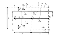
管理対象道路9の直線部における矩形区画の割り付け方法について、図4を用いて説明する。なお、カーブ部における矩形区画の割り付け方法については、後述の実施の形態2で詳細に説明する。図4に示すように、例えば基点N1に対応する矩形区画S1を形成する4つの線分のうち、隣り合う2つの基点N1、N2を結んだ線分abと平行な2つの線分de、hiの長さは、所定間隔Aと同じ長さに設定されている。また、基点N1、N2を結んだ線分abと略垂直な2つの線分dh、eiの長さは、管理対象道路9の幅W1と、その幅の両外側にGPSの測位誤差W2を足した幅W3と同じ長さである。
A method of allocating rectangular sections in the straight line portion of the
同様に、基点N2に対応する矩形区画S2を形成する4つの線分のうち、隣り合う2つの基点N2、N3を結んだ線分bcと平行な2つの線分fg、jkの長さは、所定間隔Aと同じ長さであり、線分bcと略垂直な2つの線分fj、gkの長さは、管理対象道路9の幅W1と、その幅の両外側にGPSの測位誤差W2を足した幅W3と同じ長さある。
Similarly, the four forming the rectangular section S 2 corresponding to the base point N 2 of the line, two parallel to the line segment bc connecting the two
管理対象道路9の直線部においては、隣り合う矩形区画S1、S2を、重複させることなく、また隙間をあけることなく割り付けることができ、各矩形区画S1、S2の集合(和)が交通情報処理システム1の評価管理区域となる。すなわち、評価管理区域の幅は、管理対象道路9の幅W1と、その幅の両外側にGPSの測位誤差W2を足した幅W3となり、評価管理区域の長さは、管理対象道路9の長さ(距離)である。
In the straight line portion of the
本実施の形態1では、管理対象道路9に単純な矩形区画を割り付けることにより、道路地図上において管理対象道路9を区画割りし、各矩形区画を走行する車両7から取得した走行履歴情報8により、車両7の走行位置を道路地図上に特定(マップマッチング)するものである。さらに、管理対象道路9を走行する車両7の走行履歴情報8から渋滞等の交通情報を得るためには、管理対象道路9を走行する車両であるかどうか、管理対象道路9のどの位置を走行する車両であるか、及び何台の車両が時速何キロで走行しているか、等の情報が必要である。
In the first embodiment, by assigning a simple rectangular section to the
マップマッチングの際には、以下の2つの点に留意する必要がある。1つ目は、GPSによる測位誤差を踏まえた評価をすること(データの信頼性)であり、2つ目は、多数の走行履歴情報から総合的に交通情報を算定すること(データの規範性)である。本実施の形態1では、これらの条件を踏まえて評価管理区域を設定している。 In map matching, it is necessary to pay attention to the following two points. The first is to perform evaluation based on GPS positioning errors (data reliability), and the second is to comprehensively calculate traffic information from a large number of travel history information (data normativeness). ). In the first embodiment, an evaluation management area is set based on these conditions.
本実施の形態1に係る交通情報処理システム1におけるマップマッチングの動作について、図4を用いて説明する。図4中、7a〜7iで示す矢印は、ある測定時刻期間に走行履歴情報8を伝送してきた車両7のベクトル値(ある位置における速度)を示している。このベクトル値は、走行履歴情報取得手段4が管理対象道路9を走行する車両7から取得した走行履歴情報8である緯度経度情報81及び時刻情報82をもとに算出される。
The map matching operation in the traffic
本実施の形態1では、各矩形区画S1、S2ごとに走行履歴情報8を集計し、各矩形区画S1、S2内に存在するベクトル値を抽出し、これに基づいて交通情報を算出する。図4では、基点N1に対応する矩形区画S1内に存在するベクトル値は、7a、7b、7c、7d、7eであり、7fは評価管理区域外であるため排除される。同様に、基点N2に対応する矩形区画S2内に存在するベクトル値は、7g、7h、7jであり、7iは評価管理区域外であるため排除される。
In the first embodiment, aggregates running
また、正常情報抽出手段5は、走行履歴情報取得手段4により取得した走行履歴情報8が正常な情報であるか否かを車両7ごとに判断し、正常な走行履歴情報8を抽出する。本実施の形態1では、走行履歴情報8から算出したベクトル値が評価管理区域内にある場合、その走行履歴情報8は正常な情報であると判断する。すなわち、図4では、評価管理区域外であるベクトル値7f、7iを算出するために用いた走行履歴情報8を、正常な情報ではないと判断して排除する。
Further, the normal
このように正常情報抽出手段5により正常と判断された走行履歴情報8をもとに、統計処理手段6は、各矩形区画S1、S2、S3・・を走行する車両の速度情報を算出する。さらに、算出された速度情報をもとにした統計処理により、管理対象道路9を走行した車両7の速度分布情報、具体的には管理対象道路9の特定区間の特定時刻期間における速度情報の算術平均値を求めるものである。なお、渋滞情報や目的地への所要時間等、その他の交通情報も必要に応じて求めることができる。
Thus, based on the
統計処理手段6では、車両速度、または目的地への所要時間等の具体的な数値化を行うために、収集した情報のクレンジングを含めた抽出・平均化処理が行われる。その手順について以下に説明する。まず、各車両7から伝送された走行履歴情報8を収集する。次に、過去一定期間(例えばある時刻から5分間)に収集された走行履歴情報8をベクトル化(x、y、v)する。具体的には位置差分を時刻差分で除して速度(v)を求める。
The statistical processing means 6 performs an extraction / averaging process including cleansing of the collected information in order to perform specific quantification of the vehicle speed or the required time to the destination. The procedure will be described below. First, the
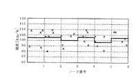
続いて、算出したベクトル値を評価管理区域である各矩形区画に当てはめて、評価管理区域外のベクトル値及び異常速度値等を除去する。その後、各矩形区画の速度(v)の平均値を算出する。例として、各矩形区画を走行した車両の平均速度を算出した結果を図5に示す。図5において、横軸はノード(基点)番号、縦軸は速度(km/h)であり、各ポイントはそれぞれの車両7の速度、太線は平均速度を示している。
Subsequently, the calculated vector value is applied to each rectangular section which is the evaluation management area, and the vector value and the abnormal speed value outside the evaluation management area are removed. Thereafter, the average value of the speed (v) of each rectangular section is calculated. As an example, FIG. 5 shows the result of calculating the average speed of a vehicle traveling in each rectangular section. In FIG. 5, the horizontal axis represents the node (base point) number, the vertical axis represents the speed (km / h), each point represents the speed of the
図5に示すように、管理対象道路9の評価管理区域を基点番号N1、N2・・に対応した矩形区画S1、S2・・で区画割りして管理し、各々の基点番号に対応する車両7の速度を算術平均することにより、管理対象道路9の特定区間において特定の時刻期間に走行した車両7の速度分布情報を求めることができる。
As shown in FIG. 5, the evaluation management area of the
以上のように、本実施の形態1によれば、管理対象道路9上の各基点N1、N2・・に対応した矩形区画S1、S2・・を設定し、この矩形区画を管理対象道路9に割り付けて管理対象道路9を区画割りするとともに、矩形区画の集合からなる評価管理区域の座標を定義するようにしたので、各矩形区画を走行する車両7から取得した走行履歴情報8から、当該車両の車両位置を容易に高い精度で特定することができる。これにより、マップマッチングの計算処理を著しく簡易化及び高速化することができ、管理対象道路9を走行した車両7に関する交通情報を求める際の計算機負荷も格段に低減させることができるため、大容量の交通量負荷への円滑な処理対応が可能である。
As described above, according to the first embodiment, the rectangular sections S 1 , S 2 ... Corresponding to the base points N 1 , N 2. Since the
さらに、本実施の形態1に係る交通情報処理システムでは、VICSにより標準化された地図情報(道路リンク)を使用せずに、道路線形に合致させた単純な矩形区画により評価管理区域を定義しているため、ユーザが新設道路等の道路図面を独自に追加、更新することも容易である。よって、新設道路等にも迅速な対応が可能であり、利便性が高く運用し易い。これらのことから、特定の地理的範囲の道路を管轄する事業者(例えば高速道路の道路管理者)及びその道路の利用者等の需要に応えることが可能なものである。 Furthermore, in the traffic information processing system according to the first embodiment, the evaluation management area is defined by a simple rectangular section that matches the road alignment without using the map information (road link) standardized by VICS. Therefore, it is easy for the user to add or update a road drawing such as a new road independently. Therefore, it is possible to quickly respond to new roads and the like, which is highly convenient and easy to operate. For these reasons, it is possible to meet the demands of business operators (for example, highway road managers) who have jurisdiction over roads in a specific geographical area and users of the roads.
実施の形態2.
上記実施の形態1では、管理対象道路9の直線部における矩形区画の割り付け方法について説明したが、実際の道路においては、図2に示すように、カーブ部を含む様々な道路線形が存在するため、各矩形区画を道路線形に沿って適切に割り付ける必要がある。本発明の実施の形態2では、管理対象道路9のカーブ部における矩形区画の割り付け方法について述べる。なお、本実施の形態2に係る交通情報処理システム1の構成は、上記実施の形態1と同様であるので図1を流用して説明する。
In the first embodiment, the method for allocating rectangular sections in the straight line portion of the
図6は、本実施の形態2の比較例である区画割り付け方法を示している。図6の比較例のように、GPS測位誤差W2を含む評価管理区域を想定し、所定間隔Aの基点で区切った評価管理領域は、直線部分においては図6に斜線で示すS1のような矩形区画となるが、カーブ部においては、図6に斜線で示すS4´のような扇型形状となる。このような扇型形状では、円弧をトレースした多角形を定義する必要が生じ、処理が複雑となる。そこで、本実施の形態2では、管理対象道路9のカーブ部においても、上記の比較例のような多角形による定義をすることなく、上記実施の形態1と同様の矩形区画を割り付け、矩形区画の集合からなる評価管理区域の座標を定義するものである。
FIG. 6 shows a partition allocation method that is a comparative example of the second embodiment. As in the comparative example of FIG. 6, assuming an evaluation management area including the GPS positioning error W 2 , the evaluation management area divided by the base point of the predetermined interval A is as shown by S 1 indicated by hatching in FIG. However, the curved portion has a fan shape such as S 4 ′ indicated by hatching in FIG. In such a fan shape, it is necessary to define a polygon obtained by tracing an arc, and the processing becomes complicated. Therefore, in the second embodiment, the rectangular sections similar to those in the first embodiment are allocated to the curved portion of the
本実施の形態2による管理対象道路9のカーブ部における矩形区画の割り付け方法について、図7及び図8を用いて説明する。図7は、本実施の形態2の他の比較例によるカーブ部における矩形区画の割り付け方法を示している。図7に示す割り付け方法では、直線部である基点N4に対応する矩形区画S4に隣接して、カーブ部である基点N5に対応する矩形区画S5を幅方向に平行にずらして割り付けしている。このような割り付け方法では、道路線形に評価管理区域が合致していない隙間部分(図7中、qrtで示す三角形領域)が発生する。また、評価管理区域として必要でない不要部分(図7中、xyzで示す三角形領域)も発生する。
A method for allocating rectangular sections in the curve portion of the
そこで、図8に示すように、カーブ部における矩形区画を実際の道路線形に合わせて、仰角θ分だけ回転させて割り付ける方法が考えられる(上記実施の形態1で用いた図3は、図8に示す割り付け方法によるものである)。これにより、図7に示す比較例よりも、道路線形に沿った矩形区画の設定を行うことができる。なお、図7及び図8において、仰角を示すθnの添え字「n」は、n番目の基点の(n+1)番目の基点に対する仰角であることを示している。 Therefore, as shown in FIG. 8, a method is conceivable in which the rectangular sections in the curve portion are aligned with the actual road alignment and rotated and assigned by the angle of elevation θ (FIG. 3 used in the first embodiment is shown in FIG. 8). It is based on the allocation method shown in Thereby, the setting of the rectangular division along road alignment can be performed rather than the comparative example shown in FIG. In FIG. 7 and FIG. 8, the subscript “n” of θ n indicating the elevation angle indicates the elevation angle of the nth base point with respect to the (n + 1) th base point.
各基点N4、N5に対応する各矩形区画S4、S5の幅は、各基点の所定間隔Aであり、一定値となっている。本実施の形態2では、各基点N4、N5に対応して同一形状の矩形区画S4、S5を割り付け、さらに(n+1)位置の基点に対する仰角θnの分だけ回転させる。図8では、各矩形区画S5を仰角θ5の分だけ回転させて割り付け、道路線形にほぼ合致した評価管理区域を設定している。 The width of each rectangular section S 4 , S 5 corresponding to each base point N 4 , N 5 is a predetermined interval A between the base points, which is a constant value. In the second embodiment, rectangular sections S 4 and S 5 having the same shape are assigned to the respective base points N 4 and N 5 , and further rotated by the elevation angle θ n with respect to the base point at the (n + 1) position. In Figure 8, allocated to the respective rectangular compartments S 5 is rotated by the amount of elevation theta 5, has set evaluation management area that substantially matches the road alignment.
なお、本実施の形態2による割り付け方法においても、上記実施の形態1と同様に、カーブ部に設けられた基点N5に対応する矩形区画S5を形成する4つの線分のうち、隣り合う2つの基点N5、N6を結んだ線分noと平行な2つの線分rt、yzの長さは、所定間隔Aと同じ長さに設定されている。また、線分noと略垂直な2つの線分ry、tzの長さは、管理対象道路9の幅W1と、その幅の両外側にGPSによる測位誤差W2を足した幅W3とほぼ同じ長さであり、これが管理評価区域の幅となる。
Also in allocation method according to the second embodiment, as in the first embodiment, among the four line segments to form a rectangular section S 5 corresponding to the base point N 5 provided in the curve section, adjacent The lengths of the two line segments rt and yz parallel to the line segment no connecting the two base points N 5 and N 6 are set to the same length as the predetermined interval A. The lengths of the two line segments ry and tz that are substantially perpendicular to the line segment no are the width W 1 of the
本実施の形態2によれば、管理対象道路9のカーブ部においても、各基点に対応して単純な矩形区画を回転させて割り付けることにより、道路線形にほぼ合致した評価管理区域を設定することができる。
According to the second embodiment, even in the curve portion of the
実施の形態3.
上記実施の形態2では、管理対象道路9のカーブ部において、各基点の所定間隔Aと同じ幅の矩形区画を、各基点に対する仰角θnの分だけ回転させて割り付けることにより、評価管理区域を設定する方法を説明した。しかし、上記実施の形態2に示した基点を中心として回転させる方法では、道路線形に評価管理区域が合致していない隙間部分(図8中、qrnで示す三角形領域)が発生し、この隙間部分に入った車両7の走行履歴情報8は排除されることになる。
In the second embodiment, the curve portion of the managed
そこで、本発明の実施の形態3では、さらに道路線形に合致した評価管理区域を設定するために、矩形区画について一定の法則に基づいた補正を行うものである。なお、本実施の形態3に係る交通情報処理システム1の構成は、上記実施の形態1と同様であるので図1を流用して説明する。
Therefore, in the third embodiment of the present invention, correction based on a certain rule is performed for a rectangular section in order to set an evaluation management area that further matches the road alignment. In addition, since the structure of the traffic
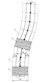
本実施の形態3による管理対象道路9のカーブ部における矩形区画の割り付け方法について、図9及び図10を用いて説明する。本実施の形態3では、図9に示すように、基点N4に対応する矩形区画S4を形成する4つの線分のうち、隣り合う2つの基点N4、N5を結んだ線分mnと平行な2つの線分pq、uxの長さを、それぞれpq´、ux´に延長し、矩形区画S4をpq´x´uで示される範囲とした。これにより、矩形区画S4の横幅(線分pq´、ux´の長さ)は、所定間隔Aではなく、評価間隔Bに延長される。
A method for allocating rectangular sections in the curve portion of the
以上のような補正を行うことにより、車両7の走行履歴情報8の抽出範囲を、図9中、qq´x´xで示す矩形領域の分だけ拡大することができ、上記実施の形態2で発生した隙間部分(図8中、qrnで示す三角形領域)をカバーすることができる。このように補正した矩形区画を管理対象道路9に割り付け、管理対象道路9を区画割りした状態を図10に示す。このように、本実施の形態3による矩形区画の割り付け方法によれば、上記実施の形態2による割り付け方法(図3)のような隙間部分が発生せず、道路線形に合致した評価管理区域を設定することができる。
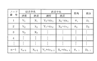
By performing the correction as described above, the extraction range of the
次に、本実施の形態3における矩形区画の補正について、具体的な手順を説明する。まず、図11に示すような初期値を設定する。具体的には、管理対象道路9の基点(ノード)の緯度経度を所定間隔で定義し、この基点の座標をもとに管理対象道路9を所定の等間隔Aで区切る。さらに、道路線形に合致した評価管理区域を設定するために、以下に示す方法で仰角、差分を求め、これをもとに評価間隔Bを求める。
Next, a specific procedure for correcting the rectangular section in the third embodiment will be described. First, initial values as shown in FIG. 11 are set. Specifically, the latitude and longitude of the base point (node) of the
評価間隔Bを設定するために必要な仰角、差分の算出方法について、図12を用いて説明する。
(1)基点N(n−1)の座標を(Xn−1、Yn−1)とする。
(2)これにより、基点Nnの座標は、(Xn+dxn−1、Yn+dyn−1)となる。
(3)その場合の仰角はθn−1となり、差分はDn−1で表される。
(4)仰角θiは、
θi=ABS(tan−1[(Yi+1−Yi)/(Xi+1−Xi)]−θi−1)
で求められる。仰角θ0は、X0、Y0から導出する
(5)差分Diは、
Di=W/tanθi
で求められる。なお、Wは評価管理区域の幅である。
また、dxi=Dicosθi、dyi=Disinθiである。
A method for calculating an elevation angle and a difference necessary for setting the evaluation interval B will be described with reference to FIG.
(1) The coordinates of the base point N (n-1) are ( Xn-1 , Yn -1 ).
(2) Thereby, the coordinates of the base point N n are (X n + dx n−1 , Y n + dy n−1 ).
(3) The elevation angle in that case is θ n−1 , and the difference is represented by D n−1 .
(4) The elevation angle θ i is
θ i = ABS (tan −1 [(Y i + 1 −Y i ) / (X i + 1 −X i )] − θ i−1 )
Is required. The elevation angle θ 0 is derived from X 0 and Y 0 (5) The difference D i is
D i = W / tan θ i
Is required. W is the width of the evaluation management area.
Also, dx i = D i cos θ i and dy i = D i sin θ i .
本実施の形態3によれば、管理対象道路9のカーブ部において、道路線形に合わせた仰角に応じて矩形区画を回転させ、さらに所定間隔Aを拡張した評価間隔Bを設定し、隣り合う矩形区画を部分的に重複させて配置することにより、道路線形に合致した隙間の無い評価管理区域を設定することができる。これにより、本実施の形態3における評価管理区域は、管理対象道路9と、その幅方向の両外側にGPSの測位誤差を足した領域を網羅することができるため、上記実施の形態2よりも多くの走行履歴情報8を取得することができ、データの規範性を高めることができる。
According to the third embodiment, in the curved portion of the
実施の形態4.
上記実施の形態1〜3では、車両7から取得した走行履歴情報8から求めた速度ベクトル値が矩形区画中にあるかどうかで正常情報か否かを判断し、マップマッチングを行った。しかし、交通情報処理システム1の評価管理区域はGPSによる測位誤差を含んでいるため、例えば図13に示すように、管理対象道路9に並行して管理対象外道路12が敷設されている場合、この管理対象外道路12を走行する車両からの走行履歴情報を排除できないという問題が生じる可能性がある。
In the first to third embodiments, whether the speed vector value obtained from the
そこで、本発明の実施の形態4では、走行履歴情報8に当該車両が管理対象道路9を走行していることを示す判断情報であるフラグ情報83が含まれる場合、そのフラグ情報83を含む走行履歴情報8は正常であると判断するようにしたものである。なお、本実施の形態4に係る交通情報処理システム1の構成は、上記実施の形態1と同様であるので図1を流用して説明する。
Therefore, in
本実施の形態4に係る交通情報処理システム1における正常情報抽出手段5の動作について、図13を用いて説明する。図13に示す例では、管理対象道路9が高速道路であり、管理対象道路9に並行して一般道である管理対象外道路12が敷設されている。この例では、評価管理区域である矩形区画S1において、走行する2台の車両71、72から走行履歴情報8が伝送される。車両71は、管理対象道路9を走行しているので管理対象の車両であり、車両72は管理対象外道路12を走行しているので、管理対象外の車両である。
The operation of the normal
本実施の形態4では、車両71が高速道路である管理対象道路9に入った時に、高速道路に入ったという情報を付与するフラグ情報83を車両71に搭載された車載器に書き込む。正常情報抽出手段5は、このフラグ情報83を読み取ることにより、車両71が管理対象道路9を走行する車両であると判断する。一方、一般道である管理対象外道路12を走行する車両72に搭載された車載器には、フラグ情報83が書き込まれないため、車両
72から伝送された走行履歴情報8は、正常でないと判断され排除される。
In the fourth embodiment, when the vehicle 71 enters the
なお、別の方法として、当該車両の走行履歴情報8を送受信した送受信機(例えば高速道路の路側に設置)の機器番号を車載器に書き込み、この機器番号によって判断する方法もある。これらの方法はいずれも車載器の標準的な製品仕様に基づいた対応方法であり、車載器の標準仕様に合致した方法を採用することが望ましい。
As another method, there is a method in which the device number of a transmitter / receiver (for example, installed on the roadside of an expressway) that transmits / receives the
本実施の形態4によれば、走行履歴情報8に当該車両が管理対象道路9を走行していることを示す判断情報であるフラグ情報83が含まれる場合に、そのフラグ情報83を含む走行履歴情報8は正常であると判断するようにしたので、さらに高い精度で正常情報を抽出することができ、より正確な交通情報の算出が可能となる。
According to the fourth embodiment, when the
本発明は、高速道路の道路管理者のような特定の地理的範囲の道路を管轄する事業者及びその道路の利用者等のユーザに交通情報を提供する交通情報処理システムとして利用することができる。 INDUSTRIAL APPLICABILITY The present invention can be used as a traffic information processing system that provides traffic information to a user such as a business operator having jurisdiction over a road in a specific geographical area, such as a road manager of an expressway, and a user of the road. .
1 交通情報処理システム、2 地図情報データベース、3 評価管理区域設定手段、4 走行履歴情報取得手段、5 正常情報抽出手段、6 統計処理手段、
7、71、72 車両、8 走行履歴情報、9 管理対象道路、10 道路の中央を示す線、11 走行方向、12 管理対象外道路、81 緯度経度情報、82 時刻情報、83 フラグ情報。
1 traffic
7, 71, 72 Vehicle, 8 Travel history information, 9 Managed road, 10 Line indicating the center of the road, 11 Travel direction, 12 Non-managed road, 81 Latitude / longitude information, 82 Time information, 83 Flag information.
Claims (5)
前記各矩形区画を走行する車両から収集された緯度経度情報及び時刻情報を含む走行履歴情報を取得する走行履歴情報取得手段、
前記走行履歴情報取得手段により取得した前記走行履歴情報が正常な情報であるか否かを車両ごとに判断し、正常な前記走行履歴情報を抽出する正常情報抽出手段、
前記正常情報抽出手段により正常と判断された前記走行履歴情報をもとに、前記各矩形区画を走行した車両の速度情報を算出し、さらに前記速度情報をもとにした統計処理により前記管理対象道路を走行した車両に関する交通情報を求める統計処理手段を備え、
前記評価管理区域設定手段は、前記管理対象道路の区画割りにおいて、前記複数の基点を前記管理対象道路の略中央を示す線上に任意の間隔で配置し、前記矩形区画を形成する4つの線分のうちの2つの線分を、隣り合う2つの前記基点を結んだ線分と略平行に配置すると共に、隣り合う2つの前記基点を結んだ線分と略垂直な2つの線分の長さを、前記管理対象道路の幅と、その幅の両外側に全地球測位システム(GPS)の測位誤差を足したものとし、前記管理対象道路のカーブ部においては、n番目の矩形区画S n を、n番目の前記基点N n の(n+1)番目の前記基点N (n+1) に対する仰角θ n 分だけ回転させて割り付けることを特徴とする交通情報処理システム。 On the road map, a plurality of base points N 1 , N 2 , N 3 ... Are arranged at intervals from each other in the traveling direction of the vehicle with respect to the management target road, and a rectangular section S set corresponding to each base point. 1 , S 2 , S 3 ... Are assigned to the management target road, the management target road is divided, and an evaluation management area setting means for defining coordinates of the evaluation management area composed of the set of rectangular sections;
Travel history information acquisition means for acquiring travel history information including latitude and longitude information and time information collected from a vehicle traveling in each rectangular section,
Normal information extraction means for determining, for each vehicle, whether or not the travel history information acquired by the travel history information acquisition means is normal information, and extracting the normal travel history information;
Based on the travel history information determined to be normal by the normal information extraction means, the speed information of the vehicle that has traveled in each rectangular section is calculated, and the management target is further calculated by statistical processing based on the speed information. Statistical processing means for obtaining traffic information on vehicles traveling on the road ,
The evaluation management area setting means arranges the plurality of base points on a line indicating a substantially center of the management target road at arbitrary intervals in the division of the management target road, and forms four rectangular segments forming the rectangular section Are arranged in parallel with the line segment connecting the two adjacent base points, and the length of the two line segments substantially perpendicular to the line segment connecting the two adjacent base points and a width of the managed road, and plus the positioning error of the global positioning system (GPS) on both outer sides in the width, the curve portion of the managed road, the n-th rectangular compartments S n The traffic information processing system is characterized in that the n-th base point N n is assigned by being rotated by an elevation angle θ n with respect to the (n + 1) -th base point N (n + 1) .
Priority Applications (1)
| Application Number | Priority Date | Filing Date | Title |
|---|---|---|---|
| JP2009137080A JP5116728B2 (en) | 2009-06-08 | 2009-06-08 | Traffic information processing system |
Applications Claiming Priority (1)
| Application Number | Priority Date | Filing Date | Title |
|---|---|---|---|
| JP2009137080A JP5116728B2 (en) | 2009-06-08 | 2009-06-08 | Traffic information processing system |
Publications (2)
| Publication Number | Publication Date |
|---|---|
| JP2010281775A JP2010281775A (en) | 2010-12-16 |
| JP5116728B2 true JP5116728B2 (en) | 2013-01-09 |
Family
ID=43538630
Family Applications (1)
| Application Number | Title | Priority Date | Filing Date |
|---|---|---|---|
| JP2009137080A Expired - Fee Related JP5116728B2 (en) | 2009-06-08 | 2009-06-08 | Traffic information processing system |
Country Status (1)
| Country | Link |
|---|---|
| JP (1) | JP5116728B2 (en) |
Cited By (1)
| Publication number | Priority date | Publication date | Assignee | Title |
|---|---|---|---|---|
| WO2019084599A1 (en) | 2017-11-03 | 2019-05-09 | Justoy Pty Limited | Storage apparatus |
Families Citing this family (3)
| Publication number | Priority date | Publication date | Assignee | Title |
|---|---|---|---|---|
| KR102098407B1 (en) * | 2014-11-18 | 2020-04-07 | 현대자동차주식회사 | Lane recognition apparatus and method |
| KR101791947B1 (en) | 2016-06-01 | 2017-11-02 | 고려대학교 산학협력단 | Driving evaluation method and apparatus based on fractal dimension analysis |
| CN117109601A (en) * | 2023-08-25 | 2023-11-24 | 上海集度汽车有限公司 | A lane matching device, method and intelligent vehicle |
Family Cites Families (7)
| Publication number | Priority date | Publication date | Assignee | Title |
|---|---|---|---|---|
| JPH10307993A (en) * | 1997-03-04 | 1998-11-17 | Sony Corp | Traffic information collection system |
| JP3568108B2 (en) * | 1999-07-28 | 2004-09-22 | 松下電器産業株式会社 | Method for transmitting location information of digital map and apparatus for implementing the method |
| JP3757265B2 (en) * | 2001-05-17 | 2006-03-22 | 国土交通省国土技術政策総合研究所長 | Travel time calculation method and travel time calculation system |
| JP4175944B2 (en) * | 2003-04-21 | 2008-11-05 | 株式会社アイ・トランスポート・ラボ | Route determination device, route determination method and route determination program |
| JP2005249506A (en) * | 2004-03-03 | 2005-09-15 | Matsushita Electric Ind Co Ltd | POSITION INFORMATION SPECIFICATION METHOD, POSITION INFORMATION TRANSMISSION DEVICE, POSITION INFORMATION RECEPTION DEVICE, AND POSITION INFORMATION SPECIFICATION SYSTEM |
| JP2007248321A (en) * | 2006-03-17 | 2007-09-27 | Sumitomo Electric Ind Ltd | Vehicle travel position estimation system and vehicle travel position estimation method |
| JP4502335B2 (en) * | 2007-03-30 | 2010-07-14 | 株式会社ナビタイムジャパン | Map display system, terminal device, map display server, and map display method |
-
2009
- 2009-06-08 JP JP2009137080A patent/JP5116728B2/en not_active Expired - Fee Related
Cited By (1)
| Publication number | Priority date | Publication date | Assignee | Title |
|---|---|---|---|---|
| WO2019084599A1 (en) | 2017-11-03 | 2019-05-09 | Justoy Pty Limited | Storage apparatus |
Also Published As
| Publication number | Publication date |
|---|---|
| JP2010281775A (en) | 2010-12-16 |
Similar Documents
| Publication | Publication Date | Title |
|---|---|---|
| JP5013211B2 (en) | Driving evaluation system and driving evaluation program | |
| CN115080672A (en) | Map updating method, map-based driving decision method and device | |
| CN101620781B (en) | System for Predicting Passenger Information, System and Method for Searching Passenger Information | |
| JP7151894B2 (en) | Map data generation system, data center and in-vehicle device | |
| EP2416120B1 (en) | Route search device, route search method, and correponding computer programm | |
| EP3143368B1 (en) | Methods and systems for detecting a partial closure of a navigable element | |
| CN100447532C (en) | Route search server, route search system, and route search method | |
| JP5547106B2 (en) | Route arithmetic unit | |
| US20190114909A1 (en) | Method and Apparatus for Identifying Congestion Bottlenecks | |
| CN102393206A (en) | Path planning method and device | |
| US6427113B1 (en) | Method for controlling traffic | |
| JP2001041757A (en) | Digital map location information transmission method and device for implementing the method | |
| JP5532024B2 (en) | Map difference data creation device and program | |
| US12195034B2 (en) | Electronic control device, control method, and automatic driving system | |
| JP2019096280A (en) | Information providing system, method and program | |
| CN101111741B (en) | Navigation device and traffic information transmission method | |
| EP2306431B1 (en) | System and method for sharing user-identified routes | |
| Jomrich et al. | Dynamic Map Update Protocol for Highly Automated Driving Vehicles. | |
| JP2019028526A (en) | Congestion prediction device | |
| JP5116728B2 (en) | Traffic information processing system | |
| CN117419735A (en) | System, method and computing device for allocating resources for vehicles | |
| WO2018021186A1 (en) | Signal control device, signal control system, signal control method, and program | |
| CN102341832A (en) | Information providing method, information providing system, information providing center and vehicle-mounted device constituting the information providing system | |
| JP2019091296A (en) | Operation management device and image generation method | |
| JP2018179519A (en) | In-vehicle device and server device |
Legal Events
| Date | Code | Title | Description |
|---|---|---|---|
| A621 | Written request for application examination |
Free format text: JAPANESE INTERMEDIATE CODE: A621 Effective date: 20110408 |
|
| A977 | Report on retrieval |
Free format text: JAPANESE INTERMEDIATE CODE: A971007 Effective date: 20120705 |
|
| A131 | Notification of reasons for refusal |
Free format text: JAPANESE INTERMEDIATE CODE: A131 Effective date: 20120710 |
|
| A521 | Written amendment |
Free format text: JAPANESE INTERMEDIATE CODE: A523 Effective date: 20120830 |
|
| TRDD | Decision of grant or rejection written | ||
| A01 | Written decision to grant a patent or to grant a registration (utility model) |
Free format text: JAPANESE INTERMEDIATE CODE: A01 Effective date: 20120918 |
|
| A01 | Written decision to grant a patent or to grant a registration (utility model) |
Free format text: JAPANESE INTERMEDIATE CODE: A01 |
|
| A61 | First payment of annual fees (during grant procedure) |
Free format text: JAPANESE INTERMEDIATE CODE: A61 Effective date: 20121016 |
|
| FPAY | Renewal fee payment (prs date is renewal date of database) |
Free format text: PAYMENT UNTIL: 20151026 Year of fee payment: 3 |
|
| LAPS | Cancellation because of no payment of annual fees |