JP5116783B2 - Water content drying equipment - Google Patents
Water content drying equipment Download PDFInfo
- Publication number
- JP5116783B2 JP5116783B2 JP2010024701A JP2010024701A JP5116783B2 JP 5116783 B2 JP5116783 B2 JP 5116783B2 JP 2010024701 A JP2010024701 A JP 2010024701A JP 2010024701 A JP2010024701 A JP 2010024701A JP 5116783 B2 JP5116783 B2 JP 5116783B2
- Authority
- JP
- Japan
- Prior art keywords
- hydrated
- hydrated material
- drying apparatus
- dryer
- dryer main
- Prior art date
- Legal status (The legal status is an assumption and is not a legal conclusion. Google has not performed a legal analysis and makes no representation as to the accuracy of the status listed.)
- Active
Links
Images


Landscapes
- Drying Of Solid Materials (AREA)
- Processing Of Solid Wastes (AREA)
- Treatment Of Sludge (AREA)
Description
本発明は、水分を含んだ含水物を減圧環境下で加熱することで乾燥させる含水物乾燥装置に関し、特に、含水物の連続した供給と乾燥後の乾燥物の連続した排出が可能な含水物乾燥装置に関するものである。 The present invention relates to a hydrated material drying apparatus that dries a hydrated product containing moisture by heating in a reduced pressure environment, and in particular, a hydrated product capable of continuously supplying the hydrated product and continuously discharging the dried product after drying. The present invention relates to a drying device.
各種バイオマスや廃棄物等の含水物を減圧環境下で加熱することで乾燥させる手段として、含水物乾燥装置が従来用いられている。この含水物乾燥装置は、密閉された装置内を減圧することによって沸点を下げ、その装置内に供給した含水物を低温で乾燥させるものである。ここで、含水物乾燥装置における被処理物としての含水物の処理方式の一種として、バッチ処理方式が挙げられる。このバッチ処理方式とは、所定量の含水物を装置内に供給した後、乾燥処理が完了するまで含水物を装置外に取り出さず、含水物を撹拌して均一な状態に保ちながら乾燥させる方式である。 As a means for drying hydrated materials such as various biomass and wastes by heating in a reduced pressure environment, a hydrated material drying apparatus has been conventionally used. This hydrated material drying apparatus lowers the boiling point by reducing the pressure in a sealed device, and dries the hydrated material supplied in the device at a low temperature. Here, a batch processing system is mentioned as a kind of processing method of the hydrated material as a to-be-processed object in a hydrated material drying apparatus. This batch processing method is a method in which a predetermined amount of hydrated material is supplied into the device, and then the hydrated material is not taken out from the device until the drying process is completed, but the hydrated material is stirred and dried while maintaining a uniform state. It is.
しかし、このバッチ処理方式では、乾燥処理の後半には水分の蒸発によって含水物の容量が大幅に減量化されるため、装置内に無駄な空間が生じ、熱放散が増加していわゆる空焚き状態になる。従ってバッチ処理方式は熱効率が悪く、乾燥処理に長時間を要するという問題がある。また、バッチ処理方式によれば、乾燥処理の初期において含水物からの水分の蒸発速度が最大となる状態を基準として、含水物乾燥装置を構成するボイラやコンデンサや冷却機器等を設計する必要がある。従って、これらの機器が過剰仕様となり、高価で大型な機器を購入することによって、コストアップ及び装置の大型化を招くという問題がある。更に、バッチ処理方式では、前述のように乾燥処理の間に含水物を撹拌するため、乾燥処理の終期には含水率が低下した乾燥物が粉塵化して装置内に飛散し、この乾燥物を装置外に排出する際に周囲を汚染するという問題もある。 However, in this batch processing method, in the latter half of the drying process, the volume of the hydrated material is greatly reduced by the evaporation of water, creating a useless space in the device, increasing heat dissipation, and so-called emptying state become. Therefore, the batch processing method has a problem that the thermal efficiency is poor and the drying process takes a long time. In addition, according to the batch processing method, it is necessary to design a boiler, a condenser, a cooling device, and the like constituting the hydrated material drying apparatus on the basis of a state in which the evaporation rate of moisture from the hydrated material is maximized in the initial stage of the drying process. is there. Therefore, these devices become over-specification, and there is a problem that purchasing expensive and large-sized devices increases costs and enlarges the apparatus. Furthermore, in the batch processing method, since the water content is agitated during the drying process as described above, the dry material having a reduced water content is pulverized and scattered in the apparatus at the end of the drying process. There is also a problem that the surroundings are contaminated when discharged outside the apparatus.
このようなバッチ処理方式の問題点を解決すべく、含水物の他の処理方式として連続処理方式が従来用いられている(例えば、特許文献1参照)。この連続処理方式とは、含水物を連続的に装置内に供給し、この含水物を一定方向に搬送しながら加熱することによって乾燥処理を行い、乾燥処理後の乾燥物を連続的に装置外に排出する方式である。そして、この連続処理方式によれば、含水物が連続的に装置内を搬送されるので、含水物の容量が乾燥に伴って減量化されても、バッチ処理方式のように装置内に無駄な空間が生じることがない。従って、連続処理方式による含水物乾燥装置では熱効率が悪化することがなく、また乾燥処理に長時間を要することもない。更に、連続処理方式では、乾燥処理の間、含水物からの水分の蒸発速度がバッチ処理方式ほど大きく変化はしない。従って、含水物乾燥装置を構成する各種機器の設計に際しては、平均的な蒸発速度を基準とすることができ、バッチ処理方式のように機器が過剰仕様となってコストアップや装置の大型化を招くこともない。更に、連続処理方式では装置内で含水物を撹拌しないので、バッチ処理方式のように乾燥物が粉塵化して装置内に飛散することもない。 In order to solve such problems of the batch processing method, a continuous processing method has been conventionally used as another processing method for water-containing materials (see, for example, Patent Document 1). In this continuous treatment method, the hydrated product is continuously supplied into the apparatus, and the hydrated product is heated while being transported in a certain direction to perform the drying process, and the dried product after the drying process is continuously removed from the apparatus. This is a method of discharging. And according to this continuous processing method, since the hydrated material is continuously conveyed in the apparatus, even if the volume of the hydrated material is reduced as it is dried, it is wasted in the apparatus like the batch processing method. There is no space. Therefore, in the hydrated material drying apparatus using the continuous processing method, the thermal efficiency does not deteriorate, and the drying process does not require a long time. Furthermore, in the continuous processing method, the evaporation rate of moisture from the hydrated material does not change as much as the batch processing method during the drying process. Therefore, when designing the various devices that make up the hydrated material drying device, the average evaporation rate can be used as a reference, resulting in excessive specification of the device as in the batch processing method, resulting in an increase in cost and size of the device. There is no invitation. Furthermore, since the hydrated material is not stirred in the apparatus in the continuous processing method, the dried material is not dusted and scattered in the device as in the batch processing method.
しかし、連続処理方式による従来の含水物乾燥装置では、含水率が十分に低くなるまで含水物を乾燥させることができないという問題がある。より詳細に説明すると、連続処理方式では、装置内を密閉した状態に保持したまま含水物を連続的に装置内に供給及び排出するために、含水物を供給及び排出するために含水物乾燥装置に設けられた供給口及び排出口の両方に、いわゆるマテリアルシールが用いられる。このマテリアルシールは、含水物や乾燥物それ自体で供給口や排出口を密閉するものである。そのため、供給口において含水物は気体を透過しない程度まで圧密された状態で供給口から供給される。また、排出口において、乾燥物もその含水率が低下し過ぎると気体を透過可能な状態となってしまいマテリアルシールを実現できないため、適度な含水率を有している必要がある。このため、含水率が60質量%以上となる範囲までしか含水物を乾燥させることができないのが通常である(特許文献1の段落[0055]参照)。 However, the conventional hydrated material drying apparatus using the continuous treatment method has a problem that the hydrated material cannot be dried until the moisture content becomes sufficiently low. More specifically, in the continuous treatment method, the hydrated material drying device for supplying and discharging the hydrated material in order to continuously supply and discharge the hydrated material in the device while keeping the inside of the device sealed. So-called material seals are used for both the supply port and the discharge port provided in the. In this material seal, the supply port and the discharge port are sealed with the hydrated material or the dried product itself. Therefore, the hydrated material is supplied from the supply port in a state of being compacted to such an extent that the gas does not pass through the supply port. In addition, if the moisture content of the dried product is too low at the discharge port, it becomes a gas permeable state and a material seal cannot be realized. Therefore, it is necessary to have an appropriate moisture content. For this reason, it is normal that a hydrated material can be dried only to the range from which a moisture content will be 60 mass% or more (refer paragraph [0055] of patent document 1).
本発明は、このような事情を考慮してなされたもので、その目的は、含水物を連続的に装置内に供給しながら乾燥物を連続的に装置外に排出する連続処理方式を採用した含水物乾燥装置において、含水率が十分に低くなるまで含水物を乾燥させることを可能にする含水物乾燥装置を提供することにある。 The present invention has been made in consideration of such circumstances, and the purpose thereof is to employ a continuous processing system in which dry matter is continuously discharged out of the apparatus while water-containing substance is continuously supplied into the apparatus. It is an object of the present invention to provide a hydrated material drying apparatus that enables a hydrated material to be dried until the moisture content becomes sufficiently low.
上記目的を達成するために、本発明は以下の手段を採用している。
すなわち、本発明に係る含水物乾燥装置は、減圧された状態の内部に含水物が供給され、該含水物を加熱しながら一定方向に搬送する乾燥機本体部と、前記乾燥機本体部の含水物搬送方向に沿って下流側にその内部を前記乾燥機本体部の内部と連通させて設けられるとともに、前記含水物を排出する排出口を気密に閉塞可能であって且つ開放可能な開閉機構を有する貯留ホッパ部と、を備え、前記貯留ホッパ部は、円筒状を成し、円筒の周面上の位置で乾燥機本体の端部開口と連通していると共に、円筒の周面上の他の位置に前記排出口が形成されているホッパ本体を有していると共に、前記開閉機構として、前記排出口を閉塞する一方で前記端部開口を塞がない位置と、該端部開口を閉塞する一方で該排出口を塞がない位置との間で、ホッパ本体の周面に沿ってスライドする蓋部材を有し、前記ホッパ本体には、減圧吸引用の配管が接続されていることを特徴とする。
この構成によれば、貯留ホッパ部に設けられた開閉機構で排出口を閉塞した状態とすれば、貯留ホッパ部の内部を乾燥機本体部の内部と同程度に減圧させることができる。一方、開閉機構で排出口を開放すれば、貯留ホッパ部に貯留された乾燥物を装置外部へ排出することができる。さらに、乾燥機本体部の端部開口を閉塞する位置へと蓋部材を移動させれば、貯留ホッパ部の排出口が開放されるとともに、乾燥機本体部の内部が密閉に保たれる。従って、乾燥物を貯留ホッパ部から装置外部へ排出する際に、蓋部材によって乾燥機本体の内部が減圧された状態のまま密閉に保たれるので、次回の乾燥処理を開始するべく蓋部材を移動させて貯留ホッパ部の排出口を閉塞すると、互いに連通した貯留ホッパ部の内部と乾燥機本体の内部とは、ある程度減圧された状態となる。これにより、乾燥処理の開始に先立って乾燥機本体部と貯留ホッパ部とを減圧するのに要する時間を短縮することができ、乾燥処理の終了から次の乾燥処理の開始までの時間を短縮することができる。
In order to achieve the above object, the present invention employs the following means.
That, hydrate drying apparatus according to the present invention, hydrous material is supplied into the vacuum state, a drying device body portion for conveying in a certain direction while heating the hydrous, water of the dryer main body portion An opening / closing mechanism provided inside the dryer main body portion in communication with the inside of the dryer main body along the material transport direction and capable of airtightly closing and opening the discharge port for discharging the water-containing material. Bei example a reservoir hopper, a with the reservoir hopper has a cylindrical shape, with and communicates with the end opening of the dryer main body at a location on the circumferential surface of the cylinder, the cylinder on the peripheral surface of the The hopper main body in which the discharge port is formed at another position, and as the opening / closing mechanism, a position where the discharge port is closed but the end opening is not blocked, and the end opening is Between the position where the outlet is closed but the outlet is not blocked, Has a lid member which slides along the circumferential surface of the body, the hopper body is characterized in that the pipe for vacuum suction is connected.
According to this configuration, when the discharge port is closed by the opening / closing mechanism provided in the storage hopper, the inside of the storage hopper can be decompressed to the same extent as the inside of the dryer main body. On the other hand, if the discharge port is opened by the opening / closing mechanism, the dry matter stored in the storage hopper can be discharged outside the apparatus. Furthermore, if the lid member is moved to a position where the end opening of the dryer main body is closed, the discharge port of the storage hopper is opened and the interior of the dryer main body is kept hermetically closed. Therefore, when the dried product is discharged from the storage hopper to the outside of the apparatus, the lid member keeps the inside of the dryer main body in a state where the pressure is reduced, so that the lid member needs to be started to start the next drying process. When it is moved to close the discharge port of the storage hopper, the interior of the storage hopper and the interior of the dryer body that are in communication with each other are in a state where the pressure is reduced to some extent. As a result, it is possible to reduce the time required to depressurize the dryer body and the storage hopper prior to the start of the drying process, and shorten the time from the end of the drying process to the start of the next drying process. be able to.
また、本発明に係る含水物乾燥装置は、前記乾燥機本体部は、含水物搬送方向に沿って設けられて回転駆動される駆動軸の周面に所定ピッチで羽根部材が突出されてなる搬送機構を有するものである。このような構成によれば、駆動軸が回転すると、含水物が羽根部材によって乾燥機本体部の内部を一定方向に搬送される。従って、含水物が含水物搬送方向に逆流して後続の含水物と混合することがないので、より確実且つ高速な含水物の搬送及び乾燥処理が可能となる。 Further, in the hydrated material drying apparatus according to the present invention, the dryer body is transported by projecting blade members at a predetermined pitch on a peripheral surface of a drive shaft that is provided along the hydrated material transporting direction and rotationally driven. It has a mechanism. According to such a configuration, when the drive shaft rotates, the hydrated material is conveyed in a fixed direction through the inside of the dryer main body by the blade member. Accordingly, since the hydrated substance does not flow backward in the hydrated substance transport direction and is mixed with the subsequent hydrated substance, the hydrated substance can be conveyed and dried more reliably and at high speed.
また、本発明に係る含水物乾燥装置は、前記羽根部材は、含水物搬送方向の位置によってピッチが異なるものである。このような構成によれば、搬送機構による含水物の搬送力が、含水物搬送方向の位置によって異なる大きさとなる。従って、含水物が例えば所定の含水率に達した時に高粘性となる特性を有する場合にも、それに応じて搬送機構の搬送力を変化させることで対応することができる。尚、本発明において「含水物の搬送力」とは、搬送機構を構成する駆動軸が含水物の粘性に逆らって回転する回転力のことを意味する。 In the hydrated material drying apparatus according to the present invention, the pitch of the blade member varies depending on the position of the hydrated material conveyance direction. According to such a structure, the conveyance force of the hydrated material by a conveyance mechanism becomes a magnitude | size which changes with positions in a hydrated material conveyance direction. Therefore, even when the hydrated material has a characteristic of becoming highly viscous when it reaches a predetermined moisture content, for example, it can be dealt with by changing the conveying force of the conveying mechanism accordingly. In the present invention, the “conveying force of the hydrated material” means a rotational force that rotates the drive shaft constituting the conveying mechanism against the viscosity of the hydrated material.
また、本発明に係る含水物乾燥装置は、前記乾燥機本体部を構成するケーシングと前記羽根部材の先端との間のクリアランスが、含水物搬送方向への位置によって異なるものである。このような構成によれば、搬送機構による含水物の搬送力が、含水物搬送方向の位置によって異なる大きさとなる。従って、含水物が例えば所定の含水率に達した時に高粘性となる特性を有する場合にも、それに応じて搬送機構の搬送力を変化させることで対応することができる。 In the hydrated material drying apparatus according to the present invention, the clearance between the casing constituting the dryer main body and the tip of the blade member differs depending on the position in the hydrated material conveyance direction. According to such a structure, the conveyance force of the hydrated material by a conveyance mechanism becomes a magnitude | size which changes with positions in a hydrated material conveyance direction. Therefore, even when the hydrated material has a characteristic of becoming highly viscous when it reaches a predetermined moisture content, for example, it can be dealt with by changing the conveying force of the conveying mechanism accordingly.
また、本発明に係る含水物乾燥装置は、前記乾燥機本体部が複数の前記搬送機構を有し、隣り合う前記搬送機構は、前記羽根部材が互いに噛み合うようにして設けられたものである。このような構成によれば、ある搬送機構の羽根部材に付着した含水物が、他の搬送機構の羽根部材によって強制的に剥離されて含水物搬送方向へと搬送される。従って、含水物が化学物質や高糖分含有物質等の高粘性物質である場合や、含水物が所定の含水率に達した時に高粘性となる特性を有する場合や、含水物が繊維質等の種々の異物を含む場合でも、搬送機構によって含水物をより確実に搬送することができる。 In the hydrated material drying apparatus according to the present invention, the dryer main body has a plurality of transport mechanisms, and the adjacent transport mechanisms are provided such that the blade members mesh with each other. According to such a configuration, the hydrated material adhering to the blade member of a certain transport mechanism is forcibly separated by the wing member of another transport mechanism and transported in the hydrated material transport direction. Therefore, when the hydrated substance is a highly viscous substance such as a chemical substance or a substance containing a high sugar content, or when the hydrated substance has a characteristic of becoming highly viscous when it reaches a predetermined moisture content, Even when various foreign substances are included, the water-containing material can be more reliably transported by the transport mechanism.
また、本発明に係る含水物乾燥装置は、前記搬送機構は、前記駆動軸の回転数を任意に変更可能であるものである。このような構成によれば、駆動軸の回転数を変化させることにより、搬送機構による含水物の搬送速度を任意に調節することができる。従って、含水物が乾燥機本体部の内部に滞留する平均時間を変化させることによって、乾燥物の含水率を任意に調節することができる。 In the hydrated material drying apparatus according to the present invention, the transport mechanism can arbitrarily change the rotational speed of the drive shaft. According to such a structure, the conveyance speed of the hydrated material by a conveyance mechanism can be arbitrarily adjusted by changing the rotation speed of a drive shaft. Therefore, the moisture content of the dried product can be arbitrarily adjusted by changing the average time that the hydrated product stays inside the dryer main body.
本発明に係る含水物乾燥装置によれば、貯留ホッパ部の内部を乾燥機本体の内部と同程度に減圧させた状態で乾燥処理を行えば、含水率が十分に低くなるまで含水物を乾燥させた後、乾燥機本体部から連続的に排出される乾燥物を貯留ホッパの内部に貯留することができる。そして、所定時間に渡って乾燥処理を行った後、排出口を開放すれば、貯留ホッパ部内の乾燥物を装置外部へ排出することができる。このように、連続的に含水物を供給し且つ連続的に乾燥物を排出しながら、含水率が十分に低くなるまで含水物を乾燥させることができる。 According to the hydrated material drying apparatus of the present invention, if the drying process is performed in a state where the inside of the storage hopper is decompressed to the same extent as the interior of the dryer body, the hydrated material is dried until the moisture content becomes sufficiently low. Then, the dried product continuously discharged from the dryer main body can be stored in the storage hopper. And after performing a drying process over predetermined time, if a discharge port is open | released, the dry matter in a storage hopper part can be discharged | emitted outside the apparatus. In this way, the hydrated product can be dried until the moisture content becomes sufficiently low while continuously supplying the hydrated product and continuously discharging the dried product.
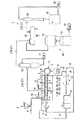
以下、図面を参照し、本発明の実施の形態について説明する。まず、第1実施形態に係る含水物乾燥装置の構成について説明する。図1は、第1実施形態に係る含水物乾燥装置1の構成を示す模式図である。含水物乾燥装置1は、含水物Gを供給するための供給口2、乾燥物Kを排出するための排出口3、含水物Gから発生した蒸気を外部に排出するための複数の排気口4、加熱用の蒸気を内部に導入するための複数の蒸気導入口5、加熱用の蒸気を外部に排出するための複数の蒸気排出口6、が設けられた減圧乾燥機7と、前記供給口2に接続された供給器8と、前記排出口3に接続された乾燥物回収器9と、前記各排気口4に接続された排気減圧ユニット10と、前記蒸気導入口5に接続された加熱器11と、この加熱器11に接続された蒸気ドレン回収器12と、を備えるものである。尚、本発明において「含水物G」とは、所定量の水分を含んだ各種バイオマスや廃棄物のことをいい、廃棄物としては下水汚泥,工場排水汚泥,食品廃棄物,生ゴミ,し尿汚泥,家畜糞尿,植物搾汁粕等が挙げられる。
Embodiments of the present invention will be described below with reference to the drawings. First, the structure of the hydrated material drying apparatus according to the first embodiment will be described. FIG. 1 is a schematic diagram illustrating a configuration of a hydrated material drying apparatus 1 according to the first embodiment. The water-containing material drying apparatus 1 includes a
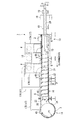
前記減圧乾燥機7は、被処理物としての含水物Gを減圧条件下で加熱することによって乾燥処理するためのものである。図2は、減圧乾燥機7の構成を示す概略縦断面図である。尚、図2では説明の便宜上、図1を反転させた状態で図示している。減圧乾燥機7は、内部で含水物Gが乾燥処理される乾燥機本体部13と、乾燥物Kすなわち乾燥処理を経て含水物Gの含水率が低下した物質が一時的に貯留される貯留ホッパ部14と、を有している。
The said vacuum dryer 7 is for drying-processing by heating the hydrated substance G as a to-be-processed object on pressure reduction conditions. FIG. 2 is a schematic longitudinal sectional view showing the configuration of the vacuum dryer 7. In FIG. 2, for convenience of explanation, FIG. 1 is shown in an inverted state. The vacuum dryer 7 includes a
乾燥機本体部13は、図2に示すように、略円筒形状を有するケーシング15の内部に、図に矢印で示す含水物搬送方向に含水物Gを搬送する2個の搬送機構16が収容されてなるものである。尚、図2では1個の搬送機構16しか図示されていないが、紙面奥側にもう1個の搬送機構16が収容されている。ケーシング15には、含水物搬送方向に沿って上流側(以下、単に「上流側」と略す)の端部に前記供給口2が設けられるとともに、この供給口2より含水物搬送方向に沿って下流側(以下、単に「下流側」と略す)の位置に所定間隔で3個の前記排気口4がそれぞれ設けられている。この3個の排気口4のうち、含水物搬送方向に沿って最も上流側に位置する第1排気口4Aと、真ん中に位置する第2排気口4Bは、最も下流側に位置する第3排気口4Cと比較して大径に形成されている。そして、各排気口4には配管17がそれぞれ接続され、第1排気口4Aに接続された第1配管17Aと第2排気口4Bに接続された第2配管17Bとが連結用配管18によって互いに接続されるとともに、第3排気口4Cに接続された第3配管17Cが第2配管17Bに接続されている。これにより、3個の排気口4から延びる各配管17はすべて連通した状態となっている。更に、ケーシング15には、含水物搬送方向に沿って所定間隔で複数の蒸気排出口6が設けられている。
As shown in FIG. 2, the dryer
一方、図2に示す2個の搬送機構16それぞれは、複数の軸受け19によって回転可能に支持されてモータ(不図示)によって回転駆動される駆動軸20と、この駆動軸20に接続されてその周面に羽根部材21が突出して設けられた中空軸22とを有している。ここで、本実施形態では、羽根部材21はいわゆるスクリュー型の形状を有しており、そのピッチPは含水物搬送方向に沿って一定の大きさとなっている。また、駆動軸20は内部が中空に形成されており、その一端側には前記蒸気導入口5と蒸気排出口6とがそれぞれ設けられている。一方、図2に詳細は示さないが、羽根部材21も内部が中空に形成されており、駆動軸20の内部と連通している。このように構成される各搬送機構16は、各駆動軸20が互いに平行するようにして、且つ、各羽根部材21が互いに噛み合うようにして、ケーシング15の内部にそれぞれ設置されている。
On the other hand, each of the two
尚、本実施形態では乾燥機本体部13を構成するケーシング15を略円筒形状としたが、ケーシング15の形状はこれに限られず、含水物搬送方向に一定の長さを有していれば、縦断面の外形を四角形や多角形等にしてもよい。また、本実施形態では羽根部材21をスクリュー型の形状としたが、その他の形状、例えばいわゆるネジ型やパドル型やスタティックミキサー型としてもよい。但し、本実施形態のようにスクリュー型とすれば、他の形状と比較して含水物Gとの接触面積が広くなるので、後述するように搬送機構16による含水物Gの加熱を効率良く行うことができるという利点がある。更に、本実施形態では搬送機構16を2個設けたが、搬送機構16の数は1個でもよく、更には3個以上の複数であってもよい。しかし、本実施形態のように2個の搬送機構16を設ければ、一方の搬送機構16の羽根部材21に付着した含水物Gが他方の搬送機構16の羽根部材21によって強制的に剥離される。従って、1個の搬送機構16を設ける場合と比較すると、含水物Gが化学物質や高糖分含有物質等の高粘性物質である場合や、含水物Gが所定の含水率に達した時に高粘性となる特性を有する場合や、含水物Gが繊維質等の種々の異物を含む場合でも、含水物Gをより確実に搬送できるという利点がある。また、3個以上の搬送機構16を設ける場合のようにコストアップや装置の大型化を招くこともない。
In this embodiment, the
図3は、図2において貯留ホッパ部14の周辺を拡大した部分拡大図である。貯留ホッパ部14は、縦断面で略円形の外形を有しており中空に形成されたホッパ本体23、及びこのホッパ本体23の周面に沿ってスライド可能に設けられた蓋部材24を有している。ホッパ本体23は、内部に乾燥物Kを貯留するための容器としての役割を果たすものである。このホッパ本体23には、その頂部に、蒸気を外部に排出するための第4排気口4Dが形成される一方、その底部に、乾燥物Kを外部に排出するための前記排出口3が形成されている。そして、第4排気口4Dには第4配管17Dが接続され、この第4配管17Dは前記第3配管17Cに接続されている。これにより、第4配管17Dも第1〜第3配管17A,17B,17Cと連通した状態となっている。このように構成される貯留ホッパ部14は、乾燥機本体部13の下流側端部に、その内部を乾燥機本体部13の内部と連通させるようにして設けられている。
FIG. 3 is a partially enlarged view in which the periphery of the
一方、蓋部材24は、ホッパ本体23の排出口3を閉塞または開放する役割を果たすものであって、排出口3を気密に閉塞する閉塞位置P1(図2に記載)から、排出口3を外部に開放する開放位置P2(図3に記載)へとスライド可能となっている。また、蓋部材24は、開放位置P2に位置した状態で、前述のように排出口3を開放すると同時に、乾燥機本体部13を構成するケーシング15の下流側の端部開口25を閉塞するようになっている。
On the other hand, the
尚、ホッパ本体23の形状は、縦断面で略円形に限られず、任意の形状に設計変更が可能である。また、蓋部材24は、開放位置に位置した状態で少なくとも排出口3を開放すれば足り、必ずしもケーシング15の端部開口25を閉塞する必要はない。
The shape of the hopper body 23 is not limited to a substantially circular shape in the longitudinal section, and the design can be changed to any shape. Further, it is sufficient for the
図1に示す前記供給器8は、減圧乾燥機7の内部に含水物Gを供給するためのものである。この供給器8は、含水物Gを圧密した状態で送出可能ないわゆる一軸偏心ネジポンプであって、供給管26を介して減圧乾燥機7の供給口2に対して接続されている。これにより、含水物Gの供給に際しては圧密された含水物Gによって供給口2が密閉されることにより、前記マテリアルシールが実現される。尚、減圧乾燥機7の内部を密閉状態に保持したままで含水物Gを供給可能であれば、必ずしもマテリアルシールに限らず、他の手段によって含水物Gを減圧乾燥機7に供給してもよい。具体的には、例えば排出側の貯留ホッパ部14と同様の構成としてもよい。また、供給器8としては、含水物Gを送出可能なその他の種別のポンプ、例えばピストンポンプ等の容積ポンプを用いてもよい。
The
図1に示す前記乾燥物回収器9は、減圧乾燥機7から排出されて落下する乾燥物Kを下方で受けて回収する容器としての役割を果たすものである。この乾燥物回収器9は、減圧乾燥機7を構成する貯留ホッパ部14の直下に、その容器開口を貯留ホッパ部14の排出口3の側に向けて配置されている。尚、図に詳細は示さないが、貯留ホッパ部14の排出口3と乾燥物回収器9とを配管で接続し、ポンプ等を用いて排出口3から乾燥物回収器9に向かって含水物Gを送出してもよい。
The
図1に示す前記排気減圧ユニット10は、減圧乾燥機7の内部から蒸気を排気するとともに、その内部を減圧させる役割を果たすものである。この排気減圧ユニット10は、前記連結用配管18に一端が接続された第1排気管27Aの他端に接続されたダスター28と、このダスター28に一端が接続された第2排気管27Bの他端に接続されたコンデンサ29と、このコンデンサ29に一端が接続された第3排気管27Cの他端に接続されたエゼクタ30と、を有している。ここで、ダスター28は、減圧乾燥機7から回収した蒸気から埃等の飛散物を除去するためのものである。このダスター28には、飛散物の捕集に使用する水を循環させるためのダスター循環ポンプ31が接続されている。また、コンデンサ29は、回収した蒸気を冷却して水分を凝集するためのものである。このコンデンサ29には、蒸気を冷却するための冷媒を循環させるために、冷媒を冷却する冷却塔32、冷却した冷媒を貯留する冷媒貯留水槽33、貯留した冷媒をコンデンサ29に向けて送出するコンデンサ循環ポンプ34がそれぞれ接続されている。また、エゼクタ30は、減圧乾燥機7から蒸気を吸引することによってその内部を減圧するためのものである。このエゼクタ30には、エゼクタ30の内部で水を高圧噴射するためのエゼクタ循環ポンプ35、エゼクタ30から回収した水を貯留する水貯留水槽36がそれぞれ接続されている。
The exhaust
図1に示す前記加熱器11は、図2に示す搬送機構16およびケーシング15を加熱するためのものである。本実施形態ではこの加熱器11としてボイラを使用し、図1及び図2に示すように、加熱器11に一端を接続した蒸気導入管37の他端を、搬送機構16を構成する駆動軸20の一端側に設けられた蒸気導入口5、及びケーシング15に設けられた複数の蒸気導入口5にそれぞれ接続している。これにより、加熱器11で生成された蒸気が、蒸気導入管37を介して供給されることによって、搬送機構16とケーシング15がそれぞれ加熱される。
The heater 11 shown in FIG. 1 is for heating the
図1に示す前記蒸気ドレン回収器12は、蒸気ドレンすなわち加熱用の蒸気が液化したものを回収して再利用するためのものである。本実施形態では、図2に示すように、蒸気ドレン回収器12に一端を接続した蒸気回収管38の他端を、駆動軸20の一端に設けられた蒸気排出口6、及びケーシング15に設けられた複数の蒸気排出口6にそれぞれ接続している。これにより、搬送機構16とケーシング15を加熱して液化した蒸気ドレンが、蒸気回収管38を介して蒸気ドレン回収器12によって回収される。そして、蒸気ドレン回収器12は回収した蒸気ドレンを加熱器11に送り、加熱器11が蒸気ドレンから蒸気を生成する。このようにして、加熱用の蒸気が再利用される。
The
次に、第1実施形態に係る含水物乾燥装置1を用いた含水物Gの乾燥処理の動作、及びその作用効果について説明する。乾燥処理の開始に際しては、まず減圧乾燥機7の内部が減圧される。具体的には、貯留ホッパ部14を構成する蓋部材24が排出口3を閉塞する閉塞位置P1に位置した状態で、図1に示すエゼクタ30が作動される。そうすると、エゼクタ30が第1〜第3排気管27A,27B,27Cを介して乾燥機本体部13から空気を吸引することにより、その内部が減圧される。この時、乾燥機本体部13の内部は貯留ホッパ部14の内部に連通しており、且つ、貯留ホッパ部14の排出口3は蓋部材24によって閉塞されているので、貯留ホッパ部14も乾燥機本体部13と同程度に減圧される。
Next, the operation | movement of the drying process of the hydrated material G using the hydrated material drying apparatus 1 which concerns on 1st Embodiment, and its effect are demonstrated. When starting the drying process, the inside of the vacuum dryer 7 is first depressurized. Specifically, the
他方、減圧乾燥機7の減圧に伴って、搬送機構16及びケーシング15の加熱が行われる。具体的には、図1に示す加熱器11から発生した蒸気が、蒸気導入管37を介して蒸気導入口5から搬送機構16の内部に送り込まれ、この蒸気が中空軸22や羽根部材21の内部空洞を循環することによって搬送機構16の全体が加熱される。また、加熱器11から発生した蒸気は、蒸気導入管37を介して複数の蒸気導入口5からケーシング15の内部にも送り込まれ、この蒸気がケーシング15の内部空洞を循環することによってケーシング15の全体が加熱される。そして、搬送機構16及びケーシング15が十分に加熱されると、次に減圧乾燥機7の内部に含水物Gが供給される。具体的には、図1に示す供給器8が作動され、供給器8から送出される含水率60〜100質量%程度の含水物Gが、供給管26を介して供給口2から乾燥機本体部13の内部に送り込まれる。
On the other hand, the
また、この含水物Gの供給開始に伴って、搬送機構16による含水物Gの搬送が開始される。具体的には、駆動軸20が不図示のモータによって回転駆動され、羽根部材21が含水物Gを含水物搬送方向に沿って上流側から下流側へ向かって搬送する。そして、搬送機構16による含水物Gの搬送が開始されると、前述のように加熱された搬送機構16やケーシング15に対して含水物Gが接触することにより、含水物Gが加熱される。これにより、含水物Gに含まれる水分が蒸発し、含水物Gは含水物搬送方向に沿って下流側に搬送されるに従ってその含水率が低下していく。そして、含水物Gは、乾燥機本体部13の最下流端に到達した時には、加熱器11によって与えられる時間当たりの熱量、或いは搬送機構16による乾燥機本体部13内での搬送時間等に応じて、その含水率が0〜60質量%程度の乾燥物Kへと変化している。
Further, with the start of supply of the hydrated material G, the conveyance of the hydrated material G by the
その後、この乾燥物Kは乾燥機本体部13の下流側の端部開口25から順次排出され、貯留ホッパ部14のホッパ本体23の内部に貯留される。ここで、前述のようにエゼクタ30によって貯留ホッパ部14も乾燥機本体部13と同程度に減圧されているので、貯留ホッパ部14に貯留された乾燥物Kは、乾燥機本体部13の最下流端部に到達した時と同程度の含水率で保持される。このように、本発明の含水物乾燥装置1によれば、乾燥機本体部13に含水物Gを連続的に供給し、且つ乾燥機本体部13から乾燥物Kを連続的に排出しながら、含水率が十分に低くなるまで含水物Gを乾燥させることができる。
Thereafter, the dried material K is sequentially discharged from the downstream end opening 25 of the dryer
そして、所定時間経過後に貯留ホッパ部14を空にする。すなわち、貯留ホッパ部14が乾燥物Kである程度一杯になったことを検知すると、減圧乾燥機7への含水物Gの供給を続けたまま、貯留ホッパ部14に貯留された乾燥物Kを装置外部へと排出する。具体的には、貯留ホッパ部14を構成する蓋部材24を図2に示す閉塞位置P1から図3に示す開放位置P2へとスライドさせることにより、ホッパ本体23の排出口3を開放する。これにより、ホッパ本体23の内部に貯留された乾燥物Kが排出口3から落下し、直下に配置された乾燥物回収器9の内部に回収される。尚、蓋部材24が開放位置P2に位置した状態では、貯留ホッパ部14の端部開口25は蓋部材24によって閉塞された状態になっている。従って、貯留ホッパ部14から乾燥物Kを排出している間は、貯留ホッパ部14の下流端まで搬送された乾燥物Kは端部開口25の付近に滞留した状態となっている。そして、貯留ホッパ部14が空になったことを検知すると、蓋部材24をスライドさせて開放位置P2から閉塞位置P1へと戻す。これにより、乾燥機本体部13から排出された乾燥物Kが、貯留ホッパ部14に順次貯留されるようになる。
And the
ところで、本実施形態では前述のように蓋部材24は開放位置P2に位置した状態で乾燥機本体部13の端部開口25を閉塞する。従って、排出口3の開放によって貯留ホッパ部14の内部は大気圧に等しくなるが、この時、蓋部材24によって密閉に保たれた乾燥機本体部13の内部は、減圧された状態のまま保持される。これにより、次回の乾燥処理を開始するべく蓋部材24を閉塞位置P1へと戻して排出口3を閉塞すると、互いに連通した貯留ホッパ部14の内部と乾燥機本体部13の内部とは、ある程度減圧された状態となる。これにより、乾燥処理の開始に先立って乾燥機本体部13と貯留ホッパ部14とをエゼクタ30で減圧するのに要する時間を短縮することができ、乾燥処理の終了から次の乾燥処理の開始までの時間を短縮することができる。
By the way, in this embodiment, as mentioned above, the
次に、第2実施形態に係る含水物乾燥装置1の構成について説明する。本実施形態の含水物乾燥装置1は、第1実施形態の含水物乾燥装置1と比較すると、図1に示す減圧乾燥機40の構成が、より詳細には乾燥機本体部41を構成する2個の搬送機構42の構成が異なっている。それ以外の構成及びその作用効果については第1実施形態と同じであるため、第1実施形態と同じ符号を用い、ここでは説明を省略する。図4は、本実施形態における乾燥機本体部41の一部を拡大した部分拡大図である。2個の搬送機構42は、第1実施形態と同様に、駆動軸43と中空軸44と羽根部材45とをそれぞれ有するが、羽根部材45の構成が第1実施形態とは異なっている。すなわち、本実施形態の羽根部材45は、第1実施形態と同様にスクリュー型の形状を有するが、そのピッチPが上流側から下流側に向かって徐々に狭くなっている。
Next, the structure of the hydrated material drying apparatus 1 according to the second embodiment will be described. Compared with the hydrated material drying apparatus 1 of the first embodiment, the hydrated material drying apparatus 1 of the present embodiment has a configuration of the
このような構成によれば、含水物Gの容量が乾燥に伴って減量化されても、熱効率が悪化しないという利点がある。より詳細に説明すると、図2に示すように、第1実施形態の羽根部材21のように含水搬送方向にピッチPが一定の大きさであると、乾燥処理が進んで含水物Gの容量が減量化される下流側では、羽根部材45の隙間には含水物Gと接触しない領域が生じる。このような領域が生じると、容積効率が低くなり、その結果熱効率が悪く乾燥処理に長時間を要してしまう。この点、本実施形態の羽根部材45のように上流側から下流側に向かってピッチPが徐々に狭くなっていると、下流側でも羽根部材45の隙間は含水物Gで満たされて無駄な領域が生じないので、容積効率を高く維持することができ、熱効率が良く乾燥処理が短時間で済む。
According to such a structure, even if the capacity | capacitance of the hydrated material G is reduced with drying, there exists an advantage that thermal efficiency does not deteriorate. More specifically, as shown in FIG. 2, when the pitch P is a constant size in the water-containing conveyance direction as in the
次に、第3実施形態に係る含水物乾燥装置1の構成について説明する。本実施形態の含水物乾燥装置1も、第1実施形態の含水物乾燥装置1と比較すると、図1に示す減圧乾燥機50の構成が、より詳細には乾燥機本体部51を構成する2個の搬送機構52の構成が異なっている。それ以外の構成及びその作用効果については第1実施形態と同じであるため、第1実施形態と同じ符号を用い、ここでは説明を省略する。図5は、本実施形態における乾燥機本体部51の一部を拡大した部分拡大図である。2個の搬送機構52は、第1実施形態と同様に、駆動軸53と中空軸54と羽根部材55とをそれぞれ有するが、羽根部材55の構成が第1実施形態とは異なっている。すなわち、本実施形態の羽根部材55は、第1実施形態と同様にスクリュー型の形状を有するが、第2実施形態とは逆に、そのピッチPが下流側から上流側に向かって徐々に狭くなっている。このような構成によれば、搬送機構52の上流部では羽根部材55が狭いピッチPで密集し、含水物Gとの接触面積が広いため、含水物Gからの水分の蒸発速度が速くなる。これにより、乾燥が進んで含水率が低下しても容量が大きく変化しないような含水物G、例えばコーヒー粕や茶滓の乾燥処理を行う場合に、乾燥初期で含水物Gの含水率がまだ高い領域である上流部において、より高速な乾燥処理を行うことができる。
Next, the structure of the hydrated material drying apparatus 1 according to the third embodiment will be described. Compared with the hydrated material drying device 1 of the first embodiment, the hydrated material drying device 1 of the present embodiment also has a configuration of the vacuum dryer 50 shown in FIG. The structures of the
次に、第4実施形態に係る含水物乾燥装置1の構成について説明する。本実施形態の含水物乾燥装置1も、第1実施形態の含水物乾燥装置1と比較すると、図1に示す減圧乾燥機60の構成が、より詳細には乾燥機本体部61を構成する2個の搬送機構62の構成が異なっている。それ以外の構成及びその作用効果については第1実施形態と同じであるため、第1実施形態と同じ符号を用い、ここでは説明を省略する。図6は、本実施形態における乾燥機本体部61の一部を拡大した部分拡大図である。2個の搬送機構62は、第1実施形態と同様に、駆動軸63と中空軸64と羽根部材65とをそれぞれ有するが、羽根部材65の構成が第1実施形態とは異なっている。すなわち、本実施形態の羽根部材65は、第1実施形態と同様にスクリュー型の形状を有するが、含水物搬送方向に沿って中央部のピッチPが、上流部及び下流部のピッチPより狭くなっている。このような構成によれば、搬送機構62の搬送力はピッチPの狭い中央部において大きくなる。これにより、含水率50〜60%付近の塑性限界水域で高粘性となる特性を有する含水物G、例えば汚泥の乾燥処理を行う場合に、含水物Gが高粘性を有する搬送機構62の中央部において、より確実且つ高速な搬送を行うことができる。
Next, the structure of the hydrated material drying apparatus 1 according to the fourth embodiment will be described. Compared with the hydrated material drying apparatus 1 of the first embodiment, the hydrated material drying apparatus 1 of this embodiment also has a configuration of the vacuum dryer 60 shown in FIG. The structures of the
次に、第5実施形態に係る含水物乾燥装置1の構成について説明する。本実施形態の含水物乾燥装置1も、第1実施形態の含水物乾燥装置1と比較すると、図1に示す減圧乾燥機70の構成が、より詳細には乾燥機本体部71を構成するケーシング72の形状が異なっている。それ以外の構成及びその作用効果については第1実施形態と同じであるため、第1実施形態と同じ符号を用い、ここでは説明を省略する。図7は、本実施形態における乾燥機本体部71の一部を拡大した部分拡大図である。乾燥機本体部71を構成するケーシング72は、その内径Dが含水物搬送方向に沿って上流側から下流側に向かって徐々に小さくなっている。
Next, the configuration of the hydrated matter drying apparatus 1 according to the fifth embodiment will be described. Compared with the hydrated material drying apparatus 1 of the first embodiment, the hydrated material drying apparatus 1 of the present embodiment also has a configuration of the vacuum dryer 70 shown in FIG. The shape of 72 is different. Since the other configuration and the operation effect are the same as those of the first embodiment, the same reference numerals as those of the first embodiment are used, and the description thereof is omitted here. FIG. 7 is an enlarged partial view of a part of the dryer
このような構成によれば、第2実施形態と同様に、含水物Gの容量が乾燥に伴って減量化されても、熱効率が悪化しないという利点がある。すなわち、本実施形態のケーシング72のように上流側から下流側に向かって内径Dが徐々に小さくなっていると、搬送機構73を構成する羽根部材74の先端とケーシング72とのクリアランスCが、上流側から下流側に向かって徐々に狭くなる。従って、乾燥処理が進んで含水物Gの容量が減量化される下流側でも、羽根部材74とケーシング72との間は含水物Gで満たされて無駄な領域が生じない。これにより、容積効率を高く維持することができ、熱効率が良く乾燥処理が短時間で済む。
According to such a configuration, similarly to the second embodiment, there is an advantage that the thermal efficiency does not deteriorate even when the volume of the hydrated product G is reduced as it is dried. That is, when the inner diameter D gradually decreases from the upstream side toward the downstream side as in the
次に、第6実施形態に係る含水物乾燥装置1の構成について説明する。本実施形態の含水物乾燥装置1も、第1実施形態の含水物乾燥装置1と比較すると、図1に示す減圧乾燥機80の構成が、より詳細には乾燥機本体部81を構成する2個の搬送機構82の構成が異なっている。それ以外の構成及びその作用効果については第1実施形態と同じであるため、第1実施形態と同じ符号を用い、ここでは説明を省略する。図8は、本実施形態における乾燥機本体部81の一部を拡大した部分拡大図である。2個の搬送機構82は、第1実施形態と同様に、駆動軸83と中空軸84と羽根部材85とをそれぞれ有するが、中空軸84の構成が第1実施形態とは異なっている。すなわち、本実施形態の各中空軸84は、その外径が上流側から下流側に向かって徐々に大きくなっている。
Next, the configuration of the hydrated matter drying apparatus 1 according to the sixth embodiment will be described. Compared with the hydrated material drying apparatus 1 of the first embodiment, the hydrated material drying apparatus 1 of this embodiment also has a configuration of the vacuum dryer 80 shown in FIG. The structures of the
このような構成によれば、第2実施形態と同様に、含水物Gの容量が乾燥に伴って減量化されても、熱効率が悪化しないという利点がある。すなわち、本実施形態の中空軸84のように上流側から下流側に向かって内径Dが徐々に大きくなっていると、第5実施形態と同様に、搬送機構82を構成する羽根部材85の先端とケーシング85とのクリアランスCが、上流側から下流側に向かって徐々に狭くなる。従って、乾燥処理が進んで含水物Gの容量が減量化される下流側でも、羽根部材85とケーシング86との間は含水物Gで満たされて無駄な領域が生じない。これにより、容積効率を高く維持することができ、熱効率が良く乾燥処理が短時間で済む。
According to such a configuration, similarly to the second embodiment, there is an advantage that the thermal efficiency does not deteriorate even when the volume of the hydrated product G is reduced as it is dried. That is, when the inner diameter D gradually increases from the upstream side toward the downstream side as in the
次に、第7実施形態に係る含水物乾燥装置1の構成について説明する。本実施形態の含水物乾燥装置1も、第1実施形態の含水物乾燥装置1と比較すると、図1に示す減圧乾燥機90の構成が、より詳細には乾燥機本体部91を構成するケーシング92の形状が異なっている。それ以外の構成及びその作用効果については第1実施形態と同じであるため、第1実施形態と同じ符号を用い、ここでは説明を省略する。図9は、本実施形態における乾燥機本体部91の一部を拡大した部分拡大図である。乾燥機本体部91を構成するケーシング92は、第5実施形態とは逆に、その内径Dが含水物搬送方向に沿って上流側から下流側に向かって徐々に大きくなっている。このような構成によれば、搬送機構93の上流部では羽根部材94の先端とケーシング92とのクリアランスCが狭く、熱伝導率が高くなるため、含水物Gからの水分の蒸発速度が速くなる。これにより、乾燥が進んで含水率が低下しても容量が大きく変化しないような含水物G、例えばコーヒー粕や茶滓の乾燥処理を行う場合に、乾燥初期で含水物Gの含水率がまだ高い領域である上流部において、より高速な乾燥処理を行うことができる。
Next, the structure of the hydrated material drying apparatus 1 according to the seventh embodiment will be described. Compared with the hydrated material drying apparatus 1 of the first embodiment, the hydrated material drying apparatus 1 of the present embodiment also has a configuration of the vacuum dryer 90 shown in FIG. The shape of 92 is different. Since the other configuration and the operation effect are the same as those of the first embodiment, the same reference numerals as those of the first embodiment are used, and the description thereof is omitted here. FIG. 9 is a partial enlarged view in which a part of the dryer
次に、第8実施形態に係る含水物乾燥装置1の構成について説明する。本実施形態の含水物乾燥装置1も、第1実施形態の含水物乾燥装置1と比較すると、図1に示す減圧乾燥機100の構成が、より詳細には乾燥機本体部101を構成する2個の搬送機構102の構成が異なっている。それ以外の構成及びその作用効果については第1実施形態と同じであるため、第1実施形態と同じ符号を用い、ここでは説明を省略する。図10は、本実施形態における乾燥機本体部101の一部を拡大した部分拡大図である。2個の搬送機構102は、第1実施形態と同様に、駆動軸103と中空軸104と羽根部材105とをそれぞれ有するが、中空軸104の構成が第1実施形態とは異なっている。すなわち、本実施形態の各中空軸104は、第6実施形態とは逆に、その外径Dが上流側から下流側に向かって徐々に小さくなっている。このような構成によれば、第7実施形態と同様に、搬送機構102の上流部では羽根部材105の先端とケーシング106とのクリアランスCが狭く、熱伝導率が高くなるため、含水物Gからの水分の蒸発速度が速くなる。これにより、第7実施形態と同様の作用効果が得られる。
Next, the configuration of the hydrated matter drying apparatus 1 according to the eighth embodiment will be described. Compared with the hydrated material drying apparatus 1 of the first embodiment, the hydrated material drying apparatus 1 of the present embodiment also has a configuration of the vacuum dryer 100 shown in FIG. The structures of the
次に、第9実施形態に係る含水物乾燥装置1の構成について説明する。本実施形態の含水物乾燥装置1も、第1実施形態の含水物乾燥装置1と比較すると、図1に示す減圧乾燥機110の構成が、より詳細には乾燥機本体部111を構成するケーシング112の形状が異なっている。それ以外の構成及びその作用効果については第1実施形態と同じであるため、第1実施形態と同じ符号を用い、ここでは説明を省略する。図11は、本実施形態における乾燥機本体部111の一部を拡大した部分拡大図である。乾燥機本体部111を構成するケーシング112は、含水物搬送方向に沿って中央部の内径Dが、上流部及び下流部の内径Dより小さくなっている。このような構成によれば、搬送機構113の搬送力は、ケーシング112の内径Dが小さい中央部で大きくなる。これにより、第4実施形態と同様の作用効果が得られる。
Next, the configuration of the hydrated matter drying apparatus 1 according to the ninth embodiment will be described. Compared with the hydrated material drying apparatus 1 of the first embodiment, the hydrated material drying apparatus 1 of the present embodiment also has a configuration of the vacuum dryer 110 shown in FIG. The shape of 112 is different. Since the other configuration and the operation effect are the same as those of the first embodiment, the same reference numerals as those of the first embodiment are used, and the description thereof is omitted here. FIG. 11 is a partially enlarged view in which a part of the dryer
次に、第10実施形態に係る含水物乾燥装置1の構成について説明する。本実施形態の含水物乾燥装置1も、第1実施形態の含水物乾燥装置1と比較すると、図1に示す減圧乾燥機120の構成が、より詳細には乾燥機本体部121を構成する2個の搬送機構122の構成が異なっている。それ以外の構成及びその作用効果については第1実施形態と同じであるため、第1実施形態と同じ符号を用い、ここでは説明を省略する。図12は、本実施形態における乾燥機本体部121の一部を拡大した部分拡大図である。2個の搬送機構122は、第1実施形態と同様に、駆動軸123と中空軸124と羽根部材125とをそれぞれ有するが、中空軸124の構成が第1実施形態とは異なっている。すなわち、本実施形態の各中空軸124は、含水物搬送方向に沿って中央部の外径Dが、上流部及び下流部の外径Dより大きくなっている。このような構成によれば、搬送機構122の搬送力は、駆動軸123の外径Dが大きい中央部で大きくなる。これにより、第4実施形態と同様の作用効果が得られる。
Next, the configuration of the hydrated matter drying apparatus 1 according to the tenth embodiment will be described. Compared with the hydrated material drying apparatus 1 of the first embodiment, the hydrated material drying apparatus 1 of the present embodiment also has a configuration of the vacuum dryer 120 shown in FIG. The structures of the
尚、搬送機構を構成する羽根部材のピッチを含水物搬送方向によって変化させることと、乾燥機本体部を構成するケーシングの内径を含水物搬送方向によって変化させることとを適宜組み合わせることも可能である。また、上述した実施の形態において示した動作手順、あるいは各構成部材の諸形状や組み合わせ等は一例であって、本発明の主旨から逸脱しない範囲において設計要求等に基づき種々変更可能である。 In addition, it is also possible to combine suitably changing the pitch of the blade member which comprises a conveyance mechanism with a hydrated material conveyance direction, and changing the internal diameter of the casing which comprises a dryer main-body part with a hydrated material conveyance direction. . Further, the operation procedure shown in the above-described embodiment, or the shapes and combinations of the constituent members are merely examples, and various modifications can be made based on design requirements and the like without departing from the gist of the present invention.
1…含水物乾燥装置
3…排出口
11…乾燥機本体部
12…貯留ホッパ部
G…含水物
DESCRIPTION OF SYMBOLS 1 ... Water content drying apparatus 3 ... Discharge port 11 ... Dryer main-
Claims (6)
前記乾燥機本体部の含水物搬送方向に沿って下流側にその内部を前記乾燥機本体部の内部と連通させて設けられるとともに、前記含水物を排出する排出口を気密に閉塞可能であって且つ開放可能な開閉機構を有する貯留ホッパ部と、
を備え、
前記貯留ホッパ部は、円筒状を成し、円筒の周面上の位置で乾燥機本体の端部開口と連通していると共に、円筒の周面上の他の位置に前記排出口が形成されているホッパ本体を有していると共に、前記開閉機構として、前記排出口を閉塞する一方で前記端部開口を塞がない位置と、該端部開口を閉塞する一方で該排出口を塞がない位置との間で、ホッパ本体の周面に沿ってスライドする蓋部材を有し、
前記ホッパ本体には、減圧吸引用の配管が接続されていることを特徴とする含水物乾燥装置。 A dryer body that is supplied with hydrated material inside the depressurized state and conveys the hydrated material in a certain direction while heating,
The inside of the dryer main body is provided on the downstream side along the hydrated material conveyance direction in communication with the inside of the dryer main body, and the discharge port for discharging the hydrated material can be airtightly closed. And a storage hopper having an openable opening and closing mechanism,
With
The storage hopper has a cylindrical shape and communicates with an end opening of the dryer body at a position on the circumferential surface of the cylinder, and the discharge port is formed at another position on the circumferential surface of the cylinder. and with and a hopper body has, as the opening and closing mechanism, a position which does not block the said end opening while closing the outlet, closed the outlet while closing the end portion opening A lid member that slides along the peripheral surface of the hopper body ,
A hydrated matter drying apparatus , wherein a vacuum suction pipe is connected to the hopper body .
Priority Applications (3)
| Application Number | Priority Date | Filing Date | Title |
|---|---|---|---|
| JP2010024701A JP5116783B2 (en) | 2010-02-05 | 2010-02-05 | Water content drying equipment |
| TW99124552A TWI410597B (en) | 2010-02-05 | 2010-07-26 | Apparatus for drying moisture materials |
| CN201010243303.8A CN102147186B (en) | 2010-02-05 | 2010-07-28 | Hydrate drying device |
Applications Claiming Priority (1)
| Application Number | Priority Date | Filing Date | Title |
|---|---|---|---|
| JP2010024701A JP5116783B2 (en) | 2010-02-05 | 2010-02-05 | Water content drying equipment |
Publications (2)
| Publication Number | Publication Date |
|---|---|
| JP2011163602A JP2011163602A (en) | 2011-08-25 |
| JP5116783B2 true JP5116783B2 (en) | 2013-01-09 |
Family
ID=44421570
Family Applications (1)
| Application Number | Title | Priority Date | Filing Date |
|---|---|---|---|
| JP2010024701A Active JP5116783B2 (en) | 2010-02-05 | 2010-02-05 | Water content drying equipment |
Country Status (3)
| Country | Link |
|---|---|
| JP (1) | JP5116783B2 (en) |
| CN (1) | CN102147186B (en) |
| TW (1) | TWI410597B (en) |
Families Citing this family (4)
| Publication number | Priority date | Publication date | Assignee | Title |
|---|---|---|---|---|
| CN105043027A (en) * | 2014-11-26 | 2015-11-11 | 安徽嘉智信诺化工有限公司 | Vacuum drying device |
| EP4431851A4 (en) | 2022-04-22 | 2025-11-19 | Nara Machinery Co Ltd | PARTICLE DRYING METHOD AND METHOD FOR MANUFACTURING A DRYING DEVICE |
| KR102523987B1 (en) * | 2022-08-16 | 2023-04-19 | 권태양 | Apparatus for feeding materials of injection machine |
| GB2629365A (en) * | 2023-04-25 | 2024-10-30 | Energy Acad Scotland Ltd | Improved apparatus and methods for treating waste |
Family Cites Families (10)
| Publication number | Priority date | Publication date | Assignee | Title |
|---|---|---|---|---|
| JPS5288979A (en) * | 1976-01-20 | 1977-07-26 | Hitachi Chem Co Ltd | Apparatus for continuously supplying slurry |
| JPS55163100U (en) * | 1979-02-06 | 1980-11-22 | ||
| CN86208216U (en) * | 1986-10-21 | 1987-09-23 | 朱天厚 | Ventilated cover-type crops-drying device with heated air or air stream |
| JPH0613159B2 (en) * | 1986-10-30 | 1994-02-23 | 株式会社マリン | Sludge treatment method |
| JPS6377700U (en) * | 1986-11-06 | 1988-05-23 | ||
| JPH09196559A (en) * | 1996-01-23 | 1997-07-31 | Hitachi Plant Eng & Constr Co Ltd | Drying equipment |
| JPH105797A (en) * | 1996-06-19 | 1998-01-13 | Y S Shoji:Kk | Vacuum discharge device |
| JP3626898B2 (en) * | 2000-06-09 | 2005-03-09 | 岩谷産業株式会社 | Solid matter separator |
| JP2002177995A (en) * | 2000-12-13 | 2002-06-25 | Nakagami Corporation:Kk | Manure processing apparatus and manure processing method |
| CN100552354C (en) * | 2007-09-20 | 2009-10-21 | 雷德启 | Double-layer return air drying device and drying method thereof |
-
2010
- 2010-02-05 JP JP2010024701A patent/JP5116783B2/en active Active
- 2010-07-26 TW TW99124552A patent/TWI410597B/en active
- 2010-07-28 CN CN201010243303.8A patent/CN102147186B/en active Active
Also Published As
| Publication number | Publication date |
|---|---|
| CN102147186A (en) | 2011-08-10 |
| JP2011163602A (en) | 2011-08-25 |
| TWI410597B (en) | 2013-10-01 |
| TW201128152A (en) | 2011-08-16 |
| CN102147186B (en) | 2014-07-16 |
Similar Documents
| Publication | Publication Date | Title |
|---|---|---|
| CN101991970B (en) | Continuous material extraction system and method | |
| CA2755039C (en) | Apparatus and method for dehydrating biological materials | |
| JP5116783B2 (en) | Water content drying equipment | |
| WO2014073203A1 (en) | Drying processing system for processing subject having fluid properties, and method for manufacturing dried object using this system | |
| JP6063196B2 (en) | Drying and concentration method and apparatus | |
| KR102060106B1 (en) | Food waste disposal system | |
| JP4326433B2 (en) | Drying equipment | |
| JP6291211B2 (en) | Drying and concentration method and apparatus | |
| JP4420737B2 (en) | Direct pressurization heat pump type processing equipment | |
| JP2018143926A (en) | Organic matter decomposition equipment | |
| JP2006017335A (en) | Continuous conductive heat transfer dryer having improved treated object dispersing performance and its operating method | |
| JP6008609B2 (en) | Drying and concentration method and apparatus | |
| JP5010166B2 (en) | Vacuum drying equipment | |
| JPH10170151A (en) | Continuous dryer | |
| JPH08136129A (en) | Water-containing material drying treatment equipment | |
| JP7171101B1 (en) | Organic decomposition equipment | |
| JP2004251523A (en) | Dryer | |
| JP2001153556A (en) | Vacuum drying device | |
| CN105066641A (en) | Vacuum microwave drying device | |
| CN206013901U (en) | Novel powder vacuum transportation device | |
| JP6523652B2 (en) | Continuous decompression solid-liquid separation device | |
| CN115479461B (en) | Degradation drying process and system for degradable plastics | |
| JP2005155980A (en) | Drying equipment | |
| CN119822099A (en) | Feeding device for deep processing in rice industry | |
| JP2002039676A (en) | Drying processing equipment |
Legal Events
| Date | Code | Title | Description |
|---|---|---|---|
| A625 | Written request for application examination (by other person) |
Free format text: JAPANESE INTERMEDIATE CODE: A625 Effective date: 20111111 |
|
| A977 | Report on retrieval |
Free format text: JAPANESE INTERMEDIATE CODE: A971007 Effective date: 20120420 |
|
| A131 | Notification of reasons for refusal |
Free format text: JAPANESE INTERMEDIATE CODE: A131 Effective date: 20120508 |
|
| A521 | Request for written amendment filed |
Free format text: JAPANESE INTERMEDIATE CODE: A523 Effective date: 20120613 |
|
| A521 | Request for written amendment filed |
Free format text: JAPANESE INTERMEDIATE CODE: A821 Effective date: 20120614 |
|
| TRDD | Decision of grant or rejection written | ||
| A01 | Written decision to grant a patent or to grant a registration (utility model) |
Free format text: JAPANESE INTERMEDIATE CODE: A01 Effective date: 20121002 |
|
| A01 | Written decision to grant a patent or to grant a registration (utility model) |
Free format text: JAPANESE INTERMEDIATE CODE: A01 |
|
| A61 | First payment of annual fees (during grant procedure) |
Free format text: JAPANESE INTERMEDIATE CODE: A61 Effective date: 20121016 |
|
| R150 | Certificate of patent or registration of utility model |
Ref document number: 5116783 Country of ref document: JP Free format text: JAPANESE INTERMEDIATE CODE: R150 Free format text: JAPANESE INTERMEDIATE CODE: R150 |
|
| FPAY | Renewal fee payment (event date is renewal date of database) |
Free format text: PAYMENT UNTIL: 20151026 Year of fee payment: 3 |
|
| R250 | Receipt of annual fees |
Free format text: JAPANESE INTERMEDIATE CODE: R250 |