JP5116923B2 - Multiprocessor control system for bicycles such as racing bicycles - Google Patents
Multiprocessor control system for bicycles such as racing bicycles Download PDFInfo
- Publication number
- JP5116923B2 JP5116923B2 JP2001092478A JP2001092478A JP5116923B2 JP 5116923 B2 JP5116923 B2 JP 5116923B2 JP 2001092478 A JP2001092478 A JP 2001092478A JP 2001092478 A JP2001092478 A JP 2001092478A JP 5116923 B2 JP5116923 B2 JP 5116923B2
- Authority
- JP
- Japan
- Prior art keywords
- processor unit
- processor
- series
- block
- unit
- Prior art date
- Legal status (The legal status is an assumption and is not a legal conclusion. Google has not performed a legal analysis and makes no representation as to the accuracy of the status listed.)
- Expired - Fee Related
Links
- 238000004891 communication Methods 0.000 claims description 40
- 230000005540 biological transmission Effects 0.000 claims description 21
- 238000012545 processing Methods 0.000 claims description 6
- 230000002457 bidirectional effect Effects 0.000 claims description 2
- 230000008878 coupling Effects 0.000 description 7
- 238000010168 coupling process Methods 0.000 description 7
- 238000005859 coupling reaction Methods 0.000 description 7
- 238000010586 diagram Methods 0.000 description 4
- 230000004913 activation Effects 0.000 description 3
- 230000002411 adverse Effects 0.000 description 2
- 230000008859 change Effects 0.000 description 2
- 230000000694 effects Effects 0.000 description 2
- 238000005265 energy consumption Methods 0.000 description 2
- 238000000034 method Methods 0.000 description 2
- 230000004044 response Effects 0.000 description 2
- 230000003213 activating effect Effects 0.000 description 1
- 230000001351 cycling effect Effects 0.000 description 1
- 238000001514 detection method Methods 0.000 description 1
- 230000009977 dual effect Effects 0.000 description 1
- 238000005516 engineering process Methods 0.000 description 1
- 238000011156 evaluation Methods 0.000 description 1
- 230000010354 integration Effects 0.000 description 1
- 230000003993 interaction Effects 0.000 description 1
- 238000007726 management method Methods 0.000 description 1
- 238000005259 measurement Methods 0.000 description 1
- 238000012544 monitoring process Methods 0.000 description 1
- 230000002093 peripheral effect Effects 0.000 description 1
- 230000008054 signal transmission Effects 0.000 description 1
- 238000012549 training Methods 0.000 description 1
Images


Classifications
-
- B—PERFORMING OPERATIONS; TRANSPORTING
- B62—LAND VEHICLES FOR TRAVELLING OTHERWISE THAN ON RAILS
- B62M—RIDER PROPULSION OF WHEELED VEHICLES OR SLEDGES; POWERED PROPULSION OF SLEDGES OR SINGLE-TRACK CYCLES; TRANSMISSIONS SPECIALLY ADAPTED FOR SUCH VEHICLES
- B62M25/00—Actuators for gearing speed-change mechanisms specially adapted for cycles
- B62M25/02—Actuators for gearing speed-change mechanisms specially adapted for cycles with mechanical transmitting systems, e.g. cables, levers
- B62M25/04—Actuators for gearing speed-change mechanisms specially adapted for cycles with mechanical transmitting systems, e.g. cables, levers hand actuated
- B62M25/045—Actuators for gearing speed-change mechanisms specially adapted for cycles with mechanical transmitting systems, e.g. cables, levers hand actuated having single actuating means operating both front and rear derailleur
-
- B—PERFORMING OPERATIONS; TRANSPORTING
- B62—LAND VEHICLES FOR TRAVELLING OTHERWISE THAN ON RAILS
- B62M—RIDER PROPULSION OF WHEELED VEHICLES OR SLEDGES; POWERED PROPULSION OF SLEDGES OR SINGLE-TRACK CYCLES; TRANSMISSIONS SPECIALLY ADAPTED FOR SUCH VEHICLES
- B62M25/00—Actuators for gearing speed-change mechanisms specially adapted for cycles
- B62M25/08—Actuators for gearing speed-change mechanisms specially adapted for cycles with electrical or fluid transmitting systems
-
- G—PHYSICS
- G01—MEASURING; TESTING
- G01C—MEASURING DISTANCES, LEVELS OR BEARINGS; SURVEYING; NAVIGATION; GYROSCOPIC INSTRUMENTS; PHOTOGRAMMETRY OR VIDEOGRAMMETRY
- G01C22/00—Measuring distance traversed on the ground by vehicles, persons, animals or other moving solid bodies, e.g. using odometers, using pedometers
- G01C22/002—Measuring distance traversed on the ground by vehicles, persons, animals or other moving solid bodies, e.g. using odometers, using pedometers for cycles
-
- H—ELECTRICITY
- H04—ELECTRIC COMMUNICATION TECHNIQUE
- H04L—TRANSMISSION OF DIGITAL INFORMATION, e.g. TELEGRAPHIC COMMUNICATION
- H04L67/00—Network arrangements or protocols for supporting network services or applications
- H04L67/01—Protocols
- H04L67/12—Protocols specially adapted for proprietary or special-purpose networking environments, e.g. medical networks, sensor networks, networks in vehicles or remote metering networks
-
- A—HUMAN NECESSITIES
- A63—SPORTS; GAMES; AMUSEMENTS
- A63B—APPARATUS FOR PHYSICAL TRAINING, GYMNASTICS, SWIMMING, CLIMBING, OR FENCING; BALL GAMES; TRAINING EQUIPMENT
- A63B24/00—Electric or electronic controls for exercising apparatus of preceding groups; Controlling or monitoring of exercises, sportive games, training or athletic performances
Landscapes
- Engineering & Computer Science (AREA)
- Chemical & Material Sciences (AREA)
- Combustion & Propulsion (AREA)
- Transportation (AREA)
- Mechanical Engineering (AREA)
- Computing Systems (AREA)
- Signal Processing (AREA)
- Radar, Positioning & Navigation (AREA)
- Remote Sensing (AREA)
- Health & Medical Sciences (AREA)
- Physics & Mathematics (AREA)
- General Health & Medical Sciences (AREA)
- Medical Informatics (AREA)
- Computer Networks & Wireless Communication (AREA)
- General Physics & Mathematics (AREA)
- Arrangements For Transmission Of Measured Signals (AREA)
- Selective Calling Equipment (AREA)
- Combined Controls Of Internal Combustion Engines (AREA)
- Control By Computers (AREA)
- Steering Devices For Bicycles And Motorcycles (AREA)
- Multi Processors (AREA)
- Control Of Vehicle Engines Or Engines For Specific Uses (AREA)
Description
【0001】
【発明の属する技術分野】
本発明は、特に競技用自転車への適用に留意して開発された、自転車用の制御システムに関する。いずれにせよこの適用可能性に関連して、特にはレース用自転車への適用可能性に関連して、本発明の適用領域を制限するものと解釈してはならない。
【0002】
【従来の技術】
自転車分野において過去数年にわたり、当該手段の使用/動作に関して各種の情報が得られるよう、例えば、自動式に作動するある判断基準に基づく場合にも、ユーザによって発せられる特定の指令に基く場合にも、アクチュエータを介して当該手段の使用/動作の条件を変更するために介在することを狙って各種性格のセンサを使用する傾向が増してきている。
【0003】
この傾向は、連続して増加する量のデータを取り出し、処理する方向において顕著であり、この結果、より精巧で連結し合ったシステムの入手の要求が高まっている。これらのシステムは、自転車に搭載されなければならないことから、特に重量、全体寸法、電気エネルギの消費の観点において、自転車の性能に悪影響を及ぼすことがないものでなければならない。
【0004】
【発明が解決しようとする課題】
本発明は、上述した問題点を解消し、この分野においてさらに高まると見られる前記必要性に応えることを目的としている。
【0005】
【課題を解決するための手段】
本発明によれば、以下のような請求項に具体化された特徴を有するシステムにより達成することができる。
簡単に言えば、本発明によるシステムは、競技用自転車などの自転車の操作を制御し管理するマルチプロセッサ電子構造に基づく。
【0006】
本発明による解決法は、自転車の機能を制御し、使用中の自転車の様子を監視するため、統合制御システムへ到達する目的でモジュール化される機能領域を特定すること、及び自転車とそのユーザとから構成されるこのシステム全体の性能の改善を図ることに基づいている。特に、機能ユニットのモジュール化から得られるアーキテクチャは、そのシステムのフレームワークでなされる信号伝達のタイミングの注意深い評価を可能とし、同時に接続数の削減を達成する。
【0007】
【発明の実施の形態】
本発明は添付図を参照した非制限的な方法で以下に示される。
符号1により全体が示される本発明に係るシステムは、通信チャンネルのレベルで相互に接続された一連の機能ブロックにより構成される。前述の機能ブロックは、後に図2により詳細に示されるように自転車、例えば競技用自転車に最適化された方法で配置が可能である。
【0008】
一般的には、システム1は基本的に以下の機能ブロックから構成される:
− システムの表示と管理のインターフェースとして機能するよう設計された第1のブロック10と;
− ユーザ自身によりなされた要求を管理するためのインターフェースとモジュールとして機能するよう設計された第2のブロック20と、であって、いずれもユーザによりなされた指令の実行と、様子、状態、及び/又は自転車の各種機能パラメータの変動、さらには特定の操作モード(例えばトレーニングセッションなど)の起動に関するものであり; このブロック20は、システムの各種他の機能ブロックとの間の通信を分類する機能を行うこともでき;そして、
− 特別な機能の制御、例えばサーボ機構要素の制御、及び/又はローカル放送ネットワーク(例えば、無線ローカルエリア・ネットワーク−WLANとして現在知られている形式のネットワーク)による通信の交換を制御するなどの役割を遂行するよう設計された第3のブロック30と、からなる。
【0009】
当該ブロックの構造をより詳細に見れば、ブロック10は通常、メインプロセッサ101を内蔵しており、これに対して1つあるいはそれ以上の押しボタン102と、さらには表示ユニット103とがつなげられていることが理解されよう。
【0010】
図2に示す内容でより分かるように、ブロック10は、自転車から選択的に取り外し可能な要素として構成されることが好ましい。この意味で、ブロック10は、特にブロック20との通信に関して、基本的にいわゆる「ユーザ・オーガナイザ」として構成される更なるブロック10aによって、少なくとも部分的に統合可能であり、重複可能であり、競合可能であるように構成されてもよい。後者の装置10aは、それ自体周知であるとみなされる。
【0011】
ブロック20は、その主要素として、通信を管理するためのプロセッサ201を含み、これには直列制御ユニット202が接続されている。同じブロック20には、例えば自転車のハンドルに配置された1つまたは複数の制御用押しボタン28、29(再度、図2参照)に接続される、入力を管理するための回線203を含むことが好ましい。このハンドルは、ブロック20が通常搭載される要素であり、好ましくはその中央部に取り付けられる。
【0012】
符号205は、回線203へ接続される1つまたは複数のセンサの可能性を示している。これらセンサは、例えば勾配センサ、高度センサ、温度センサなどである。この種のセンサは従来技術でも知られているので、ここでは詳細に説明する必要はない。
【0013】
これに関して、本発明は主に、システム1の全体のアーキテクチャ、ブロックで示すその構成、そして各ブロック間の通信及び相互作用を調整するために採用される様相(modality)に関するものであることは留意すべきである。したがって、本発明の詳細な説明は、主としてこれらの観点に関連するものであって、全体としては周知とみなされる個々の要素にまで(簡潔にするためという明白な理由により)言及しないものとする。
【0014】
ブロック30を精査することに移って、符号31は、以下に示されるようなアクチュエータ38、39のような駆動装置を制御する機能を主として遂行するよう設計されたプロセッサを示す。符号32は、符号320で示すWLAN型のローカル放送ネットワークを制御する機能を実行するよう設計された更なるプロセッサを示しており、これには1つまたは複数のセンサ41、・・・4k・・・、4nが接続されている。各センサには、例えば現在では無線周辺ユニット(WPU)と呼ばれる形式の通信インターフェース410、・・・4k0・・・、4n0のそれぞれが接続されている。
【0015】
ここでいうセンサの数n(例えば、ペダルのスピード、ペダル操作、ペダルの力、ユーザの心拍数、などを含む)や、対応するインターフェースの数はいくつであってもよい。
実際のところ、本発明に係る解決策の最も興味深い特性の1つは、他ならぬシステム1に結合されるセンサの数、及び/又は特性の選択において、非常に高い融通性を提供することである。
【0016】
ブロック30は、クランクセットに固定されたクランクホイールの位置を感知する変換器36や、あるいは自転車のチェーンの動きを感知することができる変換器を有するセンサ37のような、他のセンサや変換機からの信号をも受信できるように構成されていることが好ましい。
【0017】
符号360及び370で示される物理ラインでそれぞれブロック30に接続されるよう設計されているこれらセンサ/変換機に関してもまた、WLANネットワーク320中に含まれる様々なセンサに関して既に説明したことと同様な状況が見られる。
【0018】
各種センサ41、・・・4k・・・、4n及び36、37に関して以前に説明したものに対して基本的にデュアルとなる様相によって、この制御プロセッサ31もまた、符号38及び39で示されるような様々なアクチュエータと相互作用する。これらは、例えば自転車のギアシフト機能を制御するために前方の変速装置及び後方の変速装置に連結しているアクチュエータなどである。
【0019】
センサ36及び37の場合では、アクチュエータ38及び39との通信は、それぞれ物理ライン380、390によって行われる。これらのラインに対してはフィードバック・ライン381、391が接続されることが有利であり、例えばこれらを通してアクチュエータ38及び39は、自身の実際の位置や操作の状態をプロセッサ31に示す。
【0020】
それゆえ、ネットワーク320に接続されたセンサの場合では、センサ36及び37の数と性質や、アクチュエータ38、39のようなアクチュエータの数及び性質はどのようなものであってもよい。通信の様相に関しても、無線ネットワーク320内へ1つあるいは複数のアクチュエータの挿入を意図することが可能である。
【0021】
図2は、前述で示されたいくつか要素の自転車における可能性のある配置を示している。
ブロック10及び20、さらには制御ボタン28及び29の配置については、前に述べた。
【0022】
ブロック30は、ネットワーク320により提供される様々なセンサ41、42、43などに対してほぼ中央の位置となるボトルかご直下の位置に取り付ければ好都合である。これに関して、単に一例としてではあるが、図2ではこれらセンサの3つが、1つは前輪フォークに(センサ41)、1つはクランクセット付近に(センサ42)、そして1つは自転車の後輪フォークに沿ったほぼ中央位置に(センサ43)示されていることが分かる。ここでは単に一例として心拍数センサとして示されているセンサ44に関しては、ネットワーク320にとっては、必ずしも自転車に設置されないセンサとの通信の可能性もあることが分かる。
【0023】
センサ36は、明らかにクランクセットに対応する位置、好ましくは下部ブラケットに対応する位置に配置されており、一方センサ37は、後方変速装置に対応する位置に配置されて示されており、これによってチェーンの動きが検出され得る。アクチュエータ38は、ここではギア・シフトを制御するアクチュエータの形式で示されている。
【0024】
符号50、50A、50Bは、自転車に搭載されるバッテリなどの電力供給源の存在を例示するためもので、前記バッテリを充電するためのジェネレータを装着する構成も可能である。さらにいえば、本発明に係るシステムは、長時間の寿命を持つ小型のバッテリ(例えば、時計用のバッテリ)による供給にも十分対応していることから、これらの複数のジェネレータの存在は、全てとは言わないまでも余剰である。
【0025】
図2による表示は、図1に示す幾つかの要素が、どのように自転車に配置されるかを単に例示するのみであることは明らかであろう。したがって、この表示は、特に自転車の機能のより進んだ監視を可能とするための機能統合の可能性に関して、これらの配置が完全なもの、及び/又は制限するものと考えてはならない。
【0026】
システム1内にあるデータの通信及び処理に対する上述したような機能を達成するために関連する情報の量は、優先的と考えられる特定の技術を採用することにつながる。
【0027】
各種モジュール間、特にブロック10、20、30の間の接続は、好ましくは双方向性に、好ましくは直列フォーマットを使用した基準によりなされる。これは特に、ブロック10と20をつなぐ通信ライン12と、ブロック20と30とをつなぐ通信ライン23に対して適用される。
【0028】
上述接続のモードは、例えばブロック10とブロック30との間を直接つなぐことを避けることなど、可能な限りにおいて接続数を減らした状況でデータの送信を可能にする。
【0029】
本質的にシステムを管理するためのブロックとして機能するよう構成されたブロック10(いわゆる「サイクリング・コンピュータ」と呼ばれる機能に基本的に類似する)は、上述のように、好ましくは自転車から取り外し可能に形成され、その結果、取り付け、取り外しの検出が、ブロック10自身によっても、ブロック10と相互作用するブロック20によっても可能である。
【0030】
加えて、少なくとも最も重要な情報の流れに対して双方向通信に頼ることによって、各情報の流れの中で、より高い重要性があると見られる情報に対して明確な優先度を与えることが可能となり、さらには通信の予測可能性を保証することが可能となる。その上、このシステム(特に、ブロック30)は、電力供給源がバッテリであれジェネレータであれ、その操作状況を的確に監視することが可能である。
【0031】
加えて、このシステムは、電力消費を最適化することができる。これは、本出願人により同日にされた工業発明に対する2つの特許出願の詳細説明した基準にしたがって実現されることが好ましい。
【0032】
これに関し、ブロック20は、ブロック10を取り出し可能に装着する要素(ブラケットなど)に取り付けられることが好ましいことは理解されよう。このような取り付け形式は、好ましくはハンドル内に装着し得るラインを介して実施される押しボタン28、29と当該ブロックの通信を容易にする。
上述の構成は、ブロック20と、既に述べたようにボトルかご直下に配置されるコンテナ内に好ましくは固定されるブロック30との物理結合を可能にする。
【0033】
図3のブロック図は、ブロック10、ブロック20、ブロック30の間の物理結合がなされる好ましい様相をより詳細に示している。
図3に示すブロック図から、好ましくは非同期形式のプロトコール(つまり、同期化やクロック信号を必要としないもの)によって実施される双方向式の情報交換を可能にする観点から、結合の数を最小限に抑えることが好ましいことが分かる。
【0034】
まず、ブロック10とブロック20をつなぐライン12を精査すると、このラインは通常、グランド線86に加えて、符号84、85で示される他の2つの線から構成されていることが分かる。この2つの線すなわちラインは、それぞれブロック10からブロック20への送信と、ブロック20からブロック10への送信とを可能にするよう設計されている。
【0035】
好ましくは、この複数の線84と85は、それぞれの結合部の受信側に接合され、この線自身とグランドとの間に配置されたレジスタ10R、20R1を備えている。この複数のレジスタは、該当するブロックの間に物理結合が存在するか否かを、受信信号Rxのロジック状態を評価することによって検証することを可能にする。その信号がロジック値「0」のまま不変であれば、だれも対応する結合を駆動していないことを意味し、これは結合が存在しないことを示す。通常の結合状態では、少なくとも一時的に、送信信号Txにより高いロジックレベル(すなわち、ロジック値「1」)で受信信号が維持される。
【0036】
ほぼ同様な構成が、ブロック20をブロック30につなぐライン23に対しても採用される。
この場合には、グランド・ラインは符号83で、ブロック20からブロック30へ、及びブロック30からブロック20への送信を可能にする2つの線は、それぞれ符号81、82で示される。
この2つの線81と82も、それぞれの受信側の端末に接続された、物理結合の存在を評価可能に設計されたレジスタ20R2と30Rとを備えている。
【0037】
基本的には送信ユニットの機能を持つブロック20は、主に:
− 全ての機能ブロック10、20、30が存在して互いに結合されているとの観点から、システム1が使用可能であることを検証する; 例えば、表示ユニットの機能を有するブロック10の取り外しは、上述した方法、すなわち、レジスタ10Rの取り外しによって、ブロック20がシステム1を阻害してシステム1の全ての機能性を抑制し、あるいは少なくともブロック10の存在にリンクする機能を抑制することから検出される;
− 情報のアップデートと、そのブロック10への伝達(必要であれば処理の後)を可能にするため、ネットワーク320の制御ユニット32の周期的なポーリングを行う;
− 例えば押しボタン28、29(ブロック20に接続されるこれらの押しボタンは、簡略化のために図3には表示せず。)により発信される指令に対応した要求を処理し、当該指令(要求)を表示ユニットとして機能するブロック10、及び/又はブロック30を含む制御ユニット31に伝達することを決定できるようにする、
などの役割を畑す。
【0038】
ブロック20の活動は、電力消費を低減するため、資源の活動化の時間を低減させる基準に基づいて管理される。
【0039】
2つの機能ブロック31、32を起点するブロック30からブロック20へ向かう情報に関しては、既に述べている。
ブロック31(本質的に、アクチュエータ38、39などのアクチュエータに相互作用する機能を担う。)は、ユニット20から来る要請が絡む場合にのみ、すなわち、起動指令がある場合にのみ、反応する。
【0040】
これと対称な関係で、ネットワーク320の管理を担うブロック32は、ライン35により制御器31から送られた信号でイネーブルとされれば、ネットワーク320から来る情報を通信ユニット20へ送信する。
【0041】
この目的のために好ましくはプロトコールと物理インターフェースが使用され、これは、ブロック20と30との間の非同期式の双方向通信を可能にするためにライン81、82により送られる信号の使用に加えて、スレーブとして構成されるプロセッサ31を起動させる目的から、プロセッサ201により駆動されるさらなるライン89で入手可能な信号をも使用する。プロセッサ31で発生してライン35に存在する信号は、この場合にはスレーブとして働くプロセッサ32を制御するために、ライン82に存在する信号を開放する機能を有する。
【0042】
その結果、通常の操作状態では、情報はプロセッサ32から発生し、ユニット20に送信される。もしブロック20からプロセッサ31を送る必要がある要求があれば、それは以下の手順で行われる:
− ライン89にある信号が起動され、当該信号は、スレーブとして構成されるプロセッサ31を起動し、やはりスレーブとして構成されるプロセッサ32のためのライン35を非活動化レベルにする;
− プロセッサ32とプロセッサ201との間で行われる通信を完了させるために必要な予め定められた時間の経過後、ブロック201からの要求は、ライン81にある信号を介してプロセッサ31に到着する;
− プロセッサ32によるライン82にある信号の制御は、プロセッサ31による信号35のイネーブルレベルを介して再度イネーブルとなる;
− 一旦要求が実行されると、プロセッサ31は、プロセッサ32により、信号35を介してライン82にある信号の制御を要求し、その後、所定の時間経過の後、応答がプロセッサ31からプロセッサ201へ送られる;
− 前記応答の送信の最後に、通常の操作状態が復帰し、ライン32は、ライン35を活用して得られるイネーブルを介してライン82にある信号を制御するようイネーブルとなる。
【0043】
再度、通信ライン23において、ブロック30(これには通常、電力供給源50、50A、50Bが接続される)からブロック20への供給電圧の送達を可能とするよう設計された線90の存在が理解されよう。ブロック10には、それがシステムから取り外されたときにも供給が必要とされることから、自身で電力供給源10Bが入手可能となっている。
【0044】
ブロック30とブロック20との間の通信は、予め規定されたボーレートでバイト・フレームにより実行されることが好ましい。1つのフレームの形式は、プロセッサ32によってプロセッサ201に発生し:他のフレームの形式は、プロセッサ31とプロセッサ201に関連する。
通信は双方通行であるため、フレームの2つのメイン形式のそれぞれには、異なる状況に対する特有のサブ形式が存在する。
【0045】
通常、当該フレームの構造は、ヘッダ・バイトを含み、これは情報を送信する源(プロセッサ31、プロセッサ32、プロセッサ201など)と、フレームの特定のフォーマットを特定することを可能とし、これらには:
− プロセッサ32からプロセッサ201へ送られるデータ・ブロックと;
− ブロック30の状態と、プロセッサ31からプロセッサ201へ送られるアクチュエータの情報と;
− プロセッサ201からプロセッサ31へ送られる要求と; そして/もしくは
− プロセッサ201からプロセッサ32へ送られる要求と、
がある。
【0046】
その後、送信に関わるフレームの各タイプの特有のデータ・フィールドが続く。最終の制御バイトが、通信の成功した成果を検証するために設けられる。
【0047】
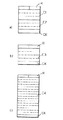
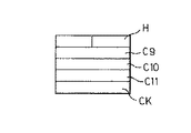
通信フレームの幾つかの例が図4から7に示されている。
この全ての図において、符号Hはヘッダ・バイトを、符号CKは、最終の制御バイトを示す。
【0048】
具体的に、a)、b)、c)の3つの部分に分けられた図4では、プロセッサ32からユニット20への情報送信に使用可能なフレームの例を示す。
例えば、図4a)は、ネットワーク320に挿入されたセンサ41などの速度センサにより生まれたデータに関する情報をブロック20へ送信するために使用可能なフレームを示す。
【0049】
前記フレームにおいて、第1のフィールドC1は、速度センサで発生したパルス数、及び/又は、予め定められた時間基準におけるこれらパルスの平均周期の値を表示するのに使用可能である。第2のフィールドC2は、ペダル操作センサなどのセンサで発生したパルスの数、及び/又は、所定時間ベースにおける平均周期の値を表示するのに使用可能である。
【0050】
図4b)は、非常に簡単なフレーム構造の可能性を示しており、ヘッダHと制御バイトCKに加え、図2に示すような心拍センサ44による測定に関する情報を送信するために使用可能な単一のフィールドC3を含む。
【0051】
例えばペダル力センサから来る情報の送信に使用可能なフレームに関し、ほぼ同様な構造が図4c)に示されている。この場合においても、フレームは、ヘッダHと制御バイトCKに加えて、例えばクランクセットの回転の間に記録された幾つかの値(例えば16の力の値)を送信するために使用可能な単一のフィールドC4を含む。
【0052】
図5は、より複雑なフレームの構造を示しており、ここでもヘッダHと制御バイトCKに加えて、複数のフィールドC5からC8が設けられ、自転車の変速装置に結合されたアクチュエータ38、39の1つの作動状態に関する情報をプロセッサ31からブロック20へ送信するために使用可能である。
この場合において、フィールドC5は、状態の情報を送信するように設計され、フィールドC6は、後方変速装置の位置、及び/又は前方変速装置の位置に関する情報を伝達する。フィールドC7とC8は、後方変速装置の位置の高さ、及び前方変速装置の位置の高さの表示を提供するために使用可能である。
【0053】
これに代わって図6は、プロセッサ201からプロセッサ31への情報の送信のために使用可能なフレーム構造を示す。この場合においても、ヘッダHと制御バイトCKに加えて、符号C9からC11で示す幾つかのフィールドが設けられ、これらはそれぞれ、要求バイト(ビット位置によって異なる)、読み取り/変更されるべき所定のアドレス、及び読み取り/変更されるべき所定の値を送るように設計されている。
【0054】
最後に、図7は、プロセッサ201から制御プロセッサ32へ情報を送信するために使用可能なフレーム構造の例を示している。この場合には、ヘッダHに続いてフィールドC12からC14が設けられ、これらはそれぞれ要求コード、対応するネットワーク320内のアドレス、及びネットワーク320の一部を形成する要素の構成パラメータを送るよう設計されている。この後に、他と同様に制御バイトCKが続く。
【0055】
好ましくは、図4から7に示すフレームに含まれる各バイトは、開始ビットに対する後縁と、2つのストップ・ビットとによって特徴付けられる。
【0056】
勿論、本発明の原則に偏ることなく、これまで説明し、図示したものに対して構成と実施の形態の詳細を広く変更することは可能であり、これによって本発明の範疇から乖離するものではない。
【0057】
【発明の効果】
競技用自転車などの自転車の操作を制御し管理するマルチプロセッサ電子構造に基づく本発明に係るシステムによれば、重量、全体寸法、電気エネルギの消費の観点から自転車の性能に悪影響を及ぼすことなく、自転車用として益々増加する傾向にあるデータ量の取り出しと処理とを可能にする、より精巧で連結し合ったシステムを提供することができる。
【0058】
加えて、本発明によるシステムによれば、少なくとも最も重要な情報の流れに対して双方向通信に頼ることによって、各情報の流れの中でより高い重要性があると見られる情報に対して明確な優先度を与えることが可能となり、さらには通信の予測可能性を保証することが可能となる。その上、当該システムは、電力供給源がバッテリであれジェネレータであれ、その操作状況を的確に監視することが可能であり、電力消費を最適化することができる。
【図面の簡単な説明】
【図1】 本発明に係るシステムの全体のアーキテクチャを示すブロック図である。
【図2】 図1に示すシステムを構成する各種モジュールが、レース用自転車などの自転車に搭載可能であることを示す概略図である。
【図3】 図1に示す幾つかの要素の具体的内容を示すブロック図である。
【図4】 本発明に係るシステム内で各種信号の送信のために採用される様相の詳細図である。
【図5】 本発明に係るシステム内で各種信号の送信のために採用される様相の詳細図である。
【図6】 本発明に係るシステム内で各種信号の送信のために採用される様相の詳細図である。
【図7】 本発明に係るシステム内で各種信号の送信のために採用される様相の詳細図である。
【符号の説明】
1.システム、 10.第1のプロセッサ・ユニット、 10R、20R、30R.センサ手段、 12、23.通信チャンネル、 20.第2のプロセッサ・ユニット、 28、29.制御要素、 30.第3のプロセッサ・ユニット、31.プロセッサ・ユニット、 32.プロセッサ、 35.制御信号、 36、37、41.センサ、 36、37.サブ・セット、 38、39.アクチュエータ、 41.サブ・セット、 50.電力供給源、 201.通信プロセッサ、 203.入力回路。[0001]
BACKGROUND OF THE INVENTION
The present invention relates to a bicycle control system that was developed with particular attention to application to racing bicycles. In any case, it should not be construed as limiting the scope of the present invention in relation to its applicability, in particular in relation to its applicability to racing bicycles.
[0002]
[Prior art]
In order to obtain various information on the use / operation of the means over the past few years in the field of bicycles, for example, based on certain criteria operating automatically, but also on the basis of specific instructions issued by the user However, there is an increasing tendency to use sensors of various characteristics with the aim of intervening to change the use / operation conditions of the means via an actuator.
[0003]
This trend is significant in the direction of extracting and processing a continuously increasing amount of data, and as a result there is a growing demand for more sophisticated and connected systems. Since these systems must be mounted on the bicycle, they must not adversely affect the performance of the bicycle, especially in terms of weight, overall dimensions, and electrical energy consumption.
[0004]
[Problems to be solved by the invention]
The present invention aims to solve the above-mentioned problems and to meet the above-mentioned need that is expected to increase further in this field.
[0005]
[Means for Solving the Problems]
According to the invention, this can be achieved by a system having the features embodied in the following claims.
Briefly, the system according to the invention is based on a multiprocessor electronic structure that controls and manages the operation of a bicycle such as a competition bicycle.
[0006]
The solution according to the invention is to identify functional areas that are modularized for the purpose of reaching the integrated control system in order to control the functions of the bicycle and monitor the state of the bicycle in use, and the bicycle and its users. It is based on improving the overall performance of this system. In particular, the architecture resulting from the modularization of functional units allows careful evaluation of the timing of signal transmissions made in the framework of the system, while at the same time reducing the number of connections.
[0007]
DETAILED DESCRIPTION OF THE INVENTION
The present invention will now be illustrated in a non-limiting manner with reference to the accompanying figures.
The system according to the invention, indicated in its entirety by the reference numeral 1, is composed of a series of functional blocks interconnected at the level of the communication channel. The aforementioned functional blocks can be arranged in a manner optimized for bicycles, for example competition bicycles, as will be shown in more detail later in FIG.
[0008]
In general, the system 1 basically consists of the following functional blocks:
A
A
The role of controlling special functions, eg control of servomechanism elements and / or the exchange of communications over a local broadcast network (eg wireless local area network—a network of the type currently known as WLAN). And a
[0009]
If the structure of the block is seen in more detail, the
[0010]
As can be seen in the context of FIG. 2, the
[0011]
The
[0012]
[0013]
In this regard, it is noted that the present invention is primarily concerned with the overall architecture of the system 1, its configuration shown in blocks, and the modalities employed to coordinate communication and interaction between each block. Should. Accordingly, the detailed description of the present invention is primarily concerned with these aspects and does not refer to individual elements that are generally considered well-known (for obvious reasons for the sake of brevity). .
[0014]
Turning to scrutinizing
[0015]
The number n of sensors (including pedal speed, pedal operation, pedal force, user heart rate, etc.) and the number of corresponding interfaces may be any number.
In fact, one of the most interesting properties of the solution according to the invention is that it offers a great deal of flexibility in the selection of the number and / or properties of sensors that are coupled to the unique system 1. is there.
[0016]
[0017]
With respect to these sensors / converters designed to be connected to the
[0018]
Due to the fundamentally dual aspect of what has been previously described with respect to the
[0019]
In the case of
[0020]
Therefore, in the case of sensors connected to network 320, the number and nature of
[0021]
FIG. 2 shows a possible arrangement in the bicycle of the several elements indicated above.
The arrangement of the
[0022]
Conveniently, the
[0023]
The
[0024]
[0025]
It will be clear that the representation according to FIG. 2 merely illustrates how the several elements shown in FIG. 1 are arranged on the bicycle. Therefore, this display should not be considered complete and / or limited in their placement, particularly with respect to the possibility of functional integration to allow for more advanced monitoring of bicycle functions.
[0026]
The amount of information associated to achieve the functions described above for the communication and processing of data in the system 1 leads to the adoption of specific technologies that are considered preferential.
[0027]
The connections between the various modules, in particular between the
[0028]
The connection mode described above enables data transmission in a situation where the number of connections is reduced as much as possible, for example, avoiding a direct connection between the
[0029]
A block 10 (essentially similar to a function called a “cycling computer”), which is configured to function essentially as a block for managing the system, is preferably removable from the bicycle as described above. As a result, attachment and removal detection is possible either by the
[0030]
In addition, by relying on two-way communication for at least the most important information flows, it is possible to give clear priority to information that appears to be of higher importance in each information flow. In addition, it becomes possible to guarantee the predictability of communication. In addition, this system (particularly block 30) can accurately monitor its operating status whether the power supply is a battery or a generator.
[0031]
In addition, the system can optimize power consumption. This is preferably achieved according to the criteria described in detail in the two patent applications for the industrial invention made on the same day by the applicant.
[0032]
In this regard, it will be appreciated that the
The arrangement described above allows physical coupling between the
[0033]
The block diagram of FIG. 3 shows in more detail the preferred aspect in which physical coupling between
From the block diagram shown in FIG. 3, the number of couplings is minimized in view of enabling bidirectional information exchange, preferably implemented by an asynchronous protocol (ie, one that does not require synchronization or clock signals). It can be seen that it is preferable to limit to the limit.
[0034]
First, a close examination of the
[0035]
Preferably, the plurality of
[0036]
A substantially similar configuration is adopted for the
In this case, the ground line is designated 83 and the two lines enabling transmission from
These two
[0037]
Basically, the
Verify that the system 1 is usable in terms of all
-Periodic polling of the
Processing requests corresponding to commands issued by, for example, push
And so on.
[0038]
The activities of
[0039]
The information from the
Block 31 (essentially responsible for interacting with actuators such as
[0040]
In a symmetrical relationship, the
[0041]
Protocols and physical interfaces are preferably used for this purpose, in addition to the use of signals sent by
[0042]
As a result, information is generated from the
The signal on
The request from
The control of the signal on
-Once the request is executed,
-At the end of sending the response, normal operating conditions are restored and
[0043]
Again, in the
[0044]
Communication between
Since communication is two-way, each of the two main types of frames has a unique sub-type for different situations.
[0045]
Typically, the structure of the frame includes a header byte, which allows to identify the source (
A data block sent from the
The state of the
A request sent from
A request sent from the
There is.
[0046]
This is followed by a specific data field for each type of frame involved in the transmission. A final control byte is provided to verify the successful outcome of the communication.
[0047]
Some examples of communication frames are shown in FIGS.
In all the figures, the symbol H indicates a header byte and the symbol CK indicates the final control byte.
[0048]
Specifically, FIG. 4 divided into three parts a), b), and c) shows an example of a frame that can be used for information transmission from the
For example, FIG. 4 a) shows a frame that can be used to send information about data generated by a speed sensor, such as
[0049]
In the frame, the first field C1 can be used to display the number of pulses generated by the speed sensor and / or the value of the average period of these pulses at a predetermined time reference. The second field C2 can be used to display the number of pulses generated by a sensor such as a pedal operation sensor and / or the value of the average period on a predetermined time basis.
[0050]
FIG. 4b) shows the possibility of a very simple frame structure, in addition to the header H and the control byte CK, a single unit that can be used to transmit information about the measurement by the heart rate sensor 44 as shown in FIG. One field C3 is included.
[0051]
A substantially similar structure is shown in FIG. 4c), for example for a frame that can be used to transmit information coming from a pedal force sensor. In this case as well, the frame is a single unit that can be used to transmit, for example, some values (eg 16 force values) recorded during rotation of the crankset in addition to the header H and the control byte CK. One field C4 is included.
[0052]
FIG. 5 shows a more complex frame structure, in which, in addition to the header H and the control byte CK, a plurality of fields C5 to C8 are also provided for the
In this case, field C5 is designed to transmit status information, and field C6 is Backward The position of the transmission, and / or Forward Transmits information about the position of the transmission. Fields C7 and C8 are Backward The height of the position of the transmission, and Forward It can be used to provide an indication of the height of the transmission position.
[0053]
Instead, FIG. 6 shows a frame structure that can be used for transmission of information from the
[0054]
Finally, FIG. 7 shows an example of a frame structure that can be used to transmit information from the
[0055]
Preferably, each byte included in the frames shown in FIGS. 4 to 7 is characterized by a trailing edge for the start bit and two stop bits.
[0056]
Of course, it is possible to widely change the configuration and details of the embodiments to those described and illustrated without departing from the principle of the present invention, and this does not depart from the scope of the present invention. Absent.
[0057]
【Effect of the invention】
The system according to the present invention based on a multiprocessor electronic structure that controls and manages the operation of a bicycle such as a competition bicycle, without adversely affecting the performance of the bicycle in terms of weight, overall dimensions, electrical energy consumption, A more elaborate and coupled system can be provided that enables the retrieval and processing of data volumes that tend to increase for bicycles.
[0058]
In addition, the system according to the invention makes it clear for information that appears to be of higher importance in each information flow by relying on two-way communication for at least the most important information flow. Priority can be given, and further, the predictability of communication can be guaranteed. Moreover, regardless of whether the power supply source is a battery or a generator, the system can accurately monitor the operation status and optimize power consumption.
[Brief description of the drawings]
FIG. 1 is a block diagram showing the overall architecture of a system according to the present invention.
FIG. 2 is a schematic view showing that various modules constituting the system shown in FIG. 1 can be mounted on a bicycle such as a race bicycle.
FIG. 3 is a block diagram showing specific contents of some elements shown in FIG. 1;
FIG. 4 is a detailed view of aspects employed for transmission of various signals in the system according to the present invention.
FIG. 5 is a detailed view of aspects employed for transmission of various signals in the system according to the present invention.
FIG. 6 is a detailed view of aspects adopted for transmission of various signals in the system according to the present invention.
FIG. 7 is a detailed view of aspects employed for transmission of various signals in the system according to the present invention.
[Explanation of symbols]
1. System, 10. The first processor unit, 10R, 20R, 30R. Sensor means 12, 23. Communication channel, 20.
Claims (19)
− 情報の処理及び表示用ユニットとして機能することができる第1のプロセッサ・ユニット(10)と;
− 通信を制御し、前記一連の制御要素(28、29)のインターフェースのユニットとして機能することができる第2のプロセッサ・ユニット(20)と;
− 前記一連のセンサ(41、…、4k、…、4n、36、37)と前記一連のアクチュエータ(38、39)とのインターフェースのユニットとして機能することができる第3のプロセッサ・ユニット(30)と、を含み、
前記第1のプロセッサ・ユニット(10)、前記第2のプロセッサ・ユニット(20)、前記第3のプロセッサ・ユニット(30)が、双方向非同期通信チャンネル(12、23)により相互につながれているシステム。Bicycle connectable to a series of sensors (41, ..., 4k, ..., 4n, 36, 37), a series of actuators (38, 39) and a series of control elements (28, 29) attached to the bike An electronic control system for:
A first processor unit (10) capable of functioning as a unit for processing and displaying information;
A second processor unit (20) that controls communication and can function as an interface unit of said series of control elements (28, 29);
A third processor unit (30) that can function as a unit of interface between the series of sensors (41, ..., 4k, ..., 4n, 36, 37) and the series of actuators (38, 39) And including
The first processor unit (10), the second processor unit (20), and the third processor unit (30) are connected to each other by a bidirectional asynchronous communication channel (12, 23). system.
− 前記一連のセンサ(41、…、4k、…、4n、36、37)によって得られたデータを、前記第3のプロセッサ・ユニット(30)から前記第2のプロセッサ・ユニット(20)へ送信すること;
− 前記第3のプロセッサ・ユニット(30)の操作状態を確かめるため、前記第2のプロセッサ・ユニット(20)から前記第3のプロセッサ・ユニット(30)へ問い質すこと;
− 前記第2のプロセッサ・ユニット(20)から前記第3のプロセッサ・ユニット(30)へ、前記一連の制御要素(28、29)から来る指令を求める要求を送ること;
− 前記第2のプロセッサ・ユニット(20)からの選択的再起動の機能によって、静止状態にある前記第3のプロセッサ・ユニット(30)を少なくとも部分的(31、32)に操作すること;
− 制御信号(35)を介して前記第3のプロセッサ・ユニット(30)から前記第2のプロセッサ・ユニット(20)への情報の伝達を選択的に可能にすること、
の内、少なくとも1つの機能を果たすことができるよう構成されていることを特徴とする、請求項1から請求項6のいずれか一に係るシステム。The second processor unit (20) and the third processor unit (30) are:
The data obtained by the series of sensors (41,..., 4k,..., 4n, 36, 37) is transmitted from the third processor unit (30) to the second processor unit (20). To do;
-Interrogating the second processor unit (20) from the second processor unit (20) to the third processor unit (30) to ascertain the operating state of the third processor unit (30);
Sending a request for instructions coming from the series of control elements (28, 29) from the second processor unit (20) to the third processor unit (30);
Operating at least partially (31, 32) the third processor unit (30) in a quiescent state by the function of selective restart from the second processor unit (20);
-Selectively enabling the transmission of information from the third processor unit (30) to the second processor unit (20) via a control signal (35);
7. The system according to claim 1, wherein the system is configured to perform at least one function.
− 前記通信チャンネル(12、23)を管理するよう構成された通信プロセッサ(201)と;
− 前記一連の制御要素(28、29)のインターフェースとして作用する入力回路(203)と、
を含むことを特徴とする、請求項1から請求項7のいずれか一に係るシステム。The second processor unit (20) is:
A communication processor (201) configured to manage the communication channels (12, 23);
An input circuit (203) acting as an interface for said series of control elements (28, 29);
The system according to any one of claims 1 to 7, characterized by comprising:
− 前記一連のセンサのサブ・セット(41、…、4k、…、4n)に関して無線式のインターフェースとして作用する各第1のプロセッサ(32)と、
− 前記一連のセンサの他のサブ・セット(36、37)と前記一連のアクチュエータ(38、39)との間の少なくとも1つに関するインターフェースとして作用することができる第2の制御プロセッサ(31)と、
を含むことを特徴とする、請求項1から請求項8のいずれか一に係るシステム。The third processor unit (30) is:
Each first processor (32) acting as a wireless interface with respect to the sub-set of sensors (41, ..., 4k, ..., 4n);
A second control processor (31) which can act as an interface for at least one of the other sub-sets (36, 37) of the series of sensors and the series of actuators (38, 39); ,
The system according to any one of claims 1 to 8, characterized by comprising:
Applications Claiming Priority (3)
| Application Number | Priority Date | Filing Date | Title |
|---|---|---|---|
| ITTO2000A000293 | 2000-03-29 | ||
| IT2000A000293 | 2000-03-29 | ||
| IT2000TO000293A IT1320286B1 (en) | 2000-03-29 | 2000-03-29 | MULTIPROCESSOR CONTROL SYSTEM FOR CYCLES, FOR EXAMPLE COMPETITION BICYCLES. |
Publications (3)
| Publication Number | Publication Date |
|---|---|
| JP2001322587A JP2001322587A (en) | 2001-11-20 |
| JP2001322587A5 JP2001322587A5 (en) | 2008-05-08 |
| JP5116923B2 true JP5116923B2 (en) | 2013-01-09 |
Family
ID=11457626
Family Applications (1)
| Application Number | Title | Priority Date | Filing Date |
|---|---|---|---|
| JP2001092478A Expired - Fee Related JP5116923B2 (en) | 2000-03-29 | 2001-03-28 | Multiprocessor control system for bicycles such as racing bicycles |
Country Status (8)
| Country | Link |
|---|---|
| US (3) | US6757567B2 (en) |
| JP (1) | JP5116923B2 (en) |
| CN (1) | CN1221916C (en) |
| CZ (1) | CZ301344B6 (en) |
| DE (1) | DE10115289B4 (en) |
| FR (1) | FR2807003B1 (en) |
| IT (1) | IT1320286B1 (en) |
| TW (1) | TW491789B (en) |
Families Citing this family (81)
| Publication number | Priority date | Publication date | Assignee | Title |
|---|---|---|---|---|
| IT1320289B1 (en) | 2000-03-29 | 2003-11-26 | Campagnolo Srl | SYSTEM FOR THE TRANSFER OF DATA, FOR EXAMPLE FOR QUALIFYING CYCLES FOR COMPETITION. |
| CN1533660B (en) * | 2001-07-20 | 2010-12-22 | Nxp股份有限公司 | Method and apparatus for identifying variable data rates |
| US7116008B2 (en) * | 2002-04-23 | 2006-10-03 | Shimano, Inc. | Electrical communication system for a bicycle |
| US7015598B2 (en) * | 2002-04-23 | 2006-03-21 | Shimano, Inc. | Power control apparatus for a bicycle |
| US6741045B2 (en) * | 2002-04-23 | 2004-05-25 | Shimano, Inc. | Bicycle control apparatus that communicates power and data over a single transmission path |
| US6724299B2 (en) * | 2002-06-27 | 2004-04-20 | Shimano, Inc. | Bicycle data communication method and apparatus |
| JP2004110628A (en) * | 2002-09-20 | 2004-04-08 | Shimano Inc | Bicycle user's information management device and cycle computer |
| JP2004256047A (en) * | 2003-02-27 | 2004-09-16 | Shimano Inc | Distance display system for bicycle and its device |
| EP1459975A1 (en) * | 2003-03-21 | 2004-09-22 | Campagnolo S.R.L. | System and method for controlling the operating functions of a cycle |
| ATE370534T1 (en) * | 2003-03-21 | 2007-09-15 | Campagnolo Srl | UNITS FOR CONTROLLING THE OPERATING FUNCTIONS OF A BICYCLE |
| ATE367305T1 (en) * | 2003-05-05 | 2007-08-15 | Campagnolo Srl | ELECTRONIC SERVO-ASSISTED BICYCLE GEAR SHIFTING |
| JP2005104258A (en) * | 2003-09-30 | 2005-04-21 | Shimano Inc | Bicycle electrical component holder |
| JP2005225426A (en) * | 2004-02-16 | 2005-08-25 | Shimano Inc | Bicycle lighting system and bicycle display device that can be fitted thereto |
| US20060079285A1 (en) * | 2004-03-31 | 2006-04-13 | Jung Edward K Y | Transmission of mote-associated index data |
| US7929914B2 (en) * | 2004-03-31 | 2011-04-19 | The Invention Science Fund I, Llc | Mote networks using directional antenna techniques |
| US7536388B2 (en) * | 2004-03-31 | 2009-05-19 | Searete, Llc | Data storage for distributed sensor networks |
| US9261383B2 (en) | 2004-07-30 | 2016-02-16 | Triplay, Inc. | Discovery of occurrence-data |
| WO2005099233A2 (en) | 2004-03-31 | 2005-10-20 | Searete Llc | Transmission of mote-associated index data |
| US8200744B2 (en) * | 2004-03-31 | 2012-06-12 | The Invention Science Fund I, Llc | Mote-associated index creation |
| US20050255841A1 (en) * | 2004-05-12 | 2005-11-17 | Searete Llc | Transmission of mote-associated log data |
| US9062992B2 (en) * | 2004-07-27 | 2015-06-23 | TriPlay Inc. | Using mote-associated indexes |
| US20060062252A1 (en) * | 2004-06-30 | 2006-03-23 | Jung Edward K | Mote appropriate network power reduction techniques |
| US7366544B2 (en) * | 2004-03-31 | 2008-04-29 | Searete, Llc | Mote networks having directional antennas |
| US20060064402A1 (en) * | 2004-07-27 | 2006-03-23 | Jung Edward K Y | Using federated mote-associated indexes |
| US20060004888A1 (en) * | 2004-05-21 | 2006-01-05 | Searete Llc, A Limited Liability Corporation Of The State Delaware | Using mote-associated logs |
| US7317898B2 (en) | 2004-03-31 | 2008-01-08 | Searete Llc | Mote networks using directional antenna techniques |
| US7389295B2 (en) * | 2004-06-25 | 2008-06-17 | Searete Llc | Using federated mote-associated logs |
| US20050265388A1 (en) * | 2004-05-12 | 2005-12-01 | Searete Llc, A Limited Liability Corporation Of The State Of Delaware | Aggregating mote-associated log data |
| US7725080B2 (en) * | 2004-03-31 | 2010-05-25 | The Invention Science Fund I, Llc | Mote networks having directional antennas |
| US8346846B2 (en) * | 2004-05-12 | 2013-01-01 | The Invention Science Fund I, Llc | Transmission of aggregated mote-associated log data |
| US20050256667A1 (en) * | 2004-05-12 | 2005-11-17 | Searete Llc, A Limited Liability Corporation Of The State Of Delaware | Federating mote-associated log data |
| US8335814B2 (en) * | 2004-03-31 | 2012-12-18 | The Invention Science Fund I, Llc | Transmission of aggregated mote-associated index data |
| US7457834B2 (en) | 2004-07-30 | 2008-11-25 | Searete, Llc | Aggregation and retrieval of network sensor data |
| US7599696B2 (en) | 2004-06-25 | 2009-10-06 | Searete, Llc | Frequency reuse techniques in mote-appropriate networks |
| US8161097B2 (en) * | 2004-03-31 | 2012-04-17 | The Invention Science Fund I, Llc | Aggregating mote-associated index data |
| US7941188B2 (en) | 2004-03-31 | 2011-05-10 | The Invention Science Fund I, Llc | Occurrence data detection and storage for generalized sensor networks |
| US20050227686A1 (en) * | 2004-03-31 | 2005-10-13 | Jung Edward K Y | Federating mote-associated index data |
| US8275824B2 (en) * | 2004-03-31 | 2012-09-25 | The Invention Science Fund I, Llc | Occurrence data detection and storage for mote networks |
| US20050267960A1 (en) * | 2004-05-12 | 2005-12-01 | Searete Llc, A Limited Liability Corporation Of The State Of Delaware | Mote-associated log creation |
| US7406367B2 (en) * | 2004-08-26 | 2008-07-29 | Shimano Inc. | Input circuit for bicycle component |
| DE102005012791A1 (en) | 2005-03-19 | 2006-09-21 | Trelock Gmbh | bike computer |
| US8028443B2 (en) | 2005-06-27 | 2011-10-04 | Nike, Inc. | Systems for activating and/or authenticating electronic devices for operation with footwear |
| US8740751B2 (en) * | 2005-07-25 | 2014-06-03 | Nike, Inc. | Interfaces and systems for displaying athletic performance information on electronic devices |
| TW200717950A (en) * | 2005-10-28 | 2007-05-01 | Shimano Kk | Bicycle wiring connector apparatus |
| US7644363B2 (en) * | 2006-04-10 | 2010-01-05 | Autodesk, Inc. | “For-each” label components in CAD drawings |
| US8188868B2 (en) | 2006-04-20 | 2012-05-29 | Nike, Inc. | Systems for activating and/or authenticating electronic devices for operation with apparel |
| EP2082952B1 (en) * | 2006-11-15 | 2011-11-16 | Good for You Good for the Planet, S.L. | Portable safety, entertainment and communication device for bicycles and control method |
| ITMI20070140A1 (en) * | 2007-01-30 | 2008-07-31 | Campagnolo Srl | MAN-BICYCLE INTERACTION DEVICE |
| US20080235493A1 (en) * | 2007-03-23 | 2008-09-25 | Qualcomm Incorporated | Instruction communication techniques for multi-processor system |
| ITMI20070737A1 (en) * | 2007-04-12 | 2008-10-13 | Campagnolo Srl | EQUIPMENT AND ELECTRONIC SYSTEM FOR BICYCLE AND RELATIVE METHODS |
| ITMI20071181A1 (en) * | 2007-06-12 | 2008-12-13 | Campagnolo Srl | ELECTRONIC CONTROL METHOD OF A BICYCLE CHANGE AND ELECTRONIC BICYCLE SYSTEM |
| ITMI20072407A1 (en) * | 2007-12-20 | 2009-06-21 | Campagnolo Srl | ELECTRONIC EQUIPMENT FOR BICYCLE |
| EP2757030B1 (en) | 2008-01-24 | 2015-12-23 | Cycling Sports Group, Inc. | Bicycle user interface system and method of operation thereof |
| US20100010709A1 (en) * | 2008-01-24 | 2010-01-14 | Cannondale Bicycle Corporation | Bicycle distributed computing arrangement and method of operation |
| EP2088071B1 (en) * | 2008-02-06 | 2013-12-11 | Campagnolo S.r.l. | Method for electronically controlling a bicycle gearshift and electronic system for a bicycle |
| US7760078B2 (en) * | 2008-06-20 | 2010-07-20 | Shimano Inc. | Wireless bicycle communication device |
| US8643722B2 (en) * | 2008-10-08 | 2014-02-04 | Cerevellum Design, Llc | Rear-view display system for a bicycle |
| US9398782B2 (en) * | 2010-04-23 | 2016-07-26 | Felt Racing, Llc | Aerodynamic bicycle helmet |
| DE102010039860A1 (en) * | 2010-08-27 | 2012-03-01 | Robert Bosch Gmbh | Vehicle e.g. electrically operated bicycle comprises accumulator, display element and sensor, that are integrated over the communication unit so that data exchange with respect to control unit is possible in both directions |
| CN102831795A (en) * | 2011-06-16 | 2012-12-19 | 恩特有限公司 | Real scene lane control system for bicycles |
| DE102011078271A1 (en) * | 2011-06-29 | 2013-01-03 | Bayerische Motoren Werke Aktiengesellschaft | Control unit for operating a motor vehicle |
| JP5247863B2 (en) * | 2011-08-29 | 2013-07-24 | 株式会社シマノ | Bicycle control device |
| DE102011053126A1 (en) * | 2011-08-30 | 2013-02-28 | B-Labs Ag | Apparatus and method for facilitating wireless communication between an actuator and a user interface |
| US9651138B2 (en) | 2011-09-30 | 2017-05-16 | Mtd Products Inc. | Speed control assembly for a self-propelled walk-behind lawn mower |
| US20130179528A1 (en) * | 2012-01-11 | 2013-07-11 | Bae Systems Controls, Inc. | Use of multicore processors for network communication in control systems |
| US8723659B2 (en) | 2012-07-10 | 2014-05-13 | Shimano Inc. | Bicycle gear shift indicator |
| US8878658B2 (en) | 2012-09-12 | 2014-11-04 | Shimano Inc. | Gear shift notification apparatus having a preselected notification pattern |
| US9394030B2 (en) | 2012-09-27 | 2016-07-19 | Sram, Llc | Rear derailleur |
| US8909424B2 (en) | 2012-10-11 | 2014-12-09 | Sram, Llc | Electronic shifting systems and methods |
| US9802669B2 (en) | 2012-10-11 | 2017-10-31 | Sram, Llc | Electronic shifting systems and methods |
| ITMI20130895A1 (en) | 2013-05-31 | 2014-12-01 | Campagnolo Srl | ELECTRONIC BICYCLE SYSTEM |
| US9676444B2 (en) | 2013-10-23 | 2017-06-13 | Sram, Llc | Electromechanical rear derailleur |
| ITMI20131902A1 (en) * | 2013-11-15 | 2015-05-16 | Campagnolo Srl | ELECTRONIC BICYCLE SYSTEM |
| US20170334522A1 (en) * | 2014-11-18 | 2017-11-23 | Vanhawks Inc. | Network-enabled bicycles, bicycles interconnected into a mesh network, electronic devices for bicycles and related methods |
| JP6730144B2 (en) | 2016-09-09 | 2020-07-29 | 株式会社シマノ | Bicycle component and its communication part |
| IT201700038213A1 (en) | 2017-04-06 | 2018-10-06 | Campagnolo Srl | Manual control device for bicycle and electronic bicycle system that includes it |
| US11192609B2 (en) * | 2018-12-27 | 2021-12-07 | Shimano Inc. | Shift control device and gear shifting device |
| US20210245006A1 (en) * | 2020-02-07 | 2021-08-12 | Includehealth, Inc. | Apparatus For Use With Exercise Equipment |
| CN112092973A (en) * | 2020-09-22 | 2020-12-18 | 重庆市科诚宜民科技有限公司 | Dedicated driving system of electric motorcycle car |
| US11945533B2 (en) | 2021-07-12 | 2024-04-02 | Sram, Llc | Bicycle component control |
| US11964725B2 (en) | 2021-08-31 | 2024-04-23 | Sram, Llc | Low power control for a control device for a bicycle |
Family Cites Families (52)
| Publication number | Priority date | Publication date | Assignee | Title |
|---|---|---|---|---|
| DE416325C (en) | 1923-07-14 | 1925-07-14 | Paul Ackermann | Dip frame for dyeing fabric in web form |
| JPS6038603B2 (en) | 1980-06-29 | 1985-09-02 | 株式会社同和 | vaporizing burner |
| FR2490367B1 (en) | 1980-09-16 | 1987-05-15 | Bull Sa | REMOVABLE ELECTRONIC MEDIA COUPLER |
| DE3149291A1 (en) | 1981-12-12 | 1983-06-23 | Robert Bosch Gmbh, 7000 Stuttgart | CIRCUIT ARRANGEMENT FOR THE OPTICAL DISPLAY OF STATE SIZES |
| FR2533025A1 (en) | 1982-09-15 | 1984-03-16 | Huret & Fils | ELECTRONIC KILOMETER, ESPECIALLY FOR A CYCLE |
| DE3445617C2 (en) | 1984-07-13 | 1987-04-16 | Max Stegmann GmbH, Uhren- und Elektroapparatefabrik, 7710 Donaueschingen | Arrangement for the serial transmission of the measured values of at least one transducer |
| IT1180107B (en) | 1984-11-05 | 1987-09-23 | Greg Di S Greganti E C Sas | DEVICE FOR REPORTING ABNORMAL PRESSURE CONDITIONS IN A MOTOR VEHICLE TIRE |
| US4613129A (en) * | 1984-11-09 | 1986-09-23 | Schroeder Charles H | Exercise bicycle attachment |
| IT8653186V0 (en) | 1986-03-25 | 1986-03-25 | Greg Di S Greganti E C S A S | PRESSURE SENSOR DEVICE FOR TIRES OF VEHICLES |
| IT1189631B (en) | 1986-03-25 | 1988-02-04 | Greg Di S Greganti & C Sas | SYSTEM FOR THE TRANSMISSION OF MESSAGES FROM A MULTIPLE OF SENSORS TOWARDS A CENTRAL UNIT ESPECIALLY FOR THE DETECTION OF OPERATING ANOMALIES IN FIXED AND MOBILE ORGANS OF MACHINES AND VEHICLES |
| US4858177A (en) * | 1987-03-27 | 1989-08-15 | Smith Harry F | Minimal connectivity parallel data processing system |
| DE3738104A1 (en) | 1987-07-09 | 1989-05-18 | Ulrich Schoberer | ENCLOSURE FOR A DEVICE |
| JPH01103043A (en) * | 1987-10-16 | 1989-04-20 | Mazda Motor Corp | Multiplex transmission equipment |
| US4780864A (en) | 1988-03-21 | 1988-10-25 | Timex Corporation | Combination wristwatch and bicycle computer |
| DE3929361A1 (en) | 1989-09-04 | 1991-03-14 | Fraunhofer Ges Forschung | TELEMETRIESENDER |
| FR2654698A1 (en) | 1989-11-17 | 1991-05-24 | Sachs Ind Sa | FUNCTIONAL AND ERGONOMIC STEERING BODY WITH INTEGRATED CONTROL CENTER FOR CYCLE. |
| DE4004981C1 (en) | 1990-02-19 | 1991-05-16 | Dietrich Gerhard 7800 Freiburg De Ellsaesser | Bicycle computer registering working data - indicates gear ratio setting, RPM of pedal crank and has sensor measuring wind pressure |
| US5059158A (en) * | 1990-05-08 | 1991-10-22 | E.B.T., Inc. | Electronic transmission control system for a bicycle |
| US5231872A (en) | 1991-02-21 | 1993-08-03 | Ttc/Truck Tech Corp. | Tire monitoring apparatus and method |
| DE4113316C2 (en) * | 1991-04-24 | 2003-09-11 | Bosch Gmbh Robert | Connection circuit for a lambda probe and test method for such a circuit |
| JPH05347649A (en) | 1991-12-03 | 1993-12-27 | Mitsubishi Electric Corp | Data communication system |
| DE4205911A1 (en) | 1992-02-26 | 1993-09-02 | Uwatec Ag | CONTROL DEVICE FOR THE AIR PRESSURE OF AIR TIRED VEHICLE WHEELS |
| JPH05347651A (en) | 1992-06-15 | 1993-12-27 | Fujitsu Ltd | Pause time setting circuit between data frames |
| JP2985511B2 (en) | 1992-06-15 | 1999-12-06 | 株式会社日立製作所 | Data receiving system and communication control device |
| US5261858A (en) | 1992-06-19 | 1993-11-16 | Browning Automatic Transmission | Method and system for computer-controlled bicycle gear shifting |
| US5298885A (en) * | 1992-08-21 | 1994-03-29 | Basic Measuring Instruments | Harmonic measuring instrument for AC power systems with poly-phase threshold means |
| US5527239A (en) | 1993-02-04 | 1996-06-18 | Abbondanza; James M. | Pulse rate controlled exercise system |
| US5435315A (en) | 1994-01-28 | 1995-07-25 | Mcphee; Ron J. | Physical fitness evalution system |
| US5551315A (en) * | 1994-02-03 | 1996-09-03 | Pikoulas; George W. | Automatic gear changing system |
| JPH0897818A (en) * | 1994-09-21 | 1996-04-12 | Nec Corp | Wide area network management system |
| US5644511A (en) * | 1995-04-26 | 1997-07-01 | Mcwhorter; Gary T. | Cyclometer computer |
| US5599244A (en) * | 1995-08-14 | 1997-02-04 | Ethington; Russell A. | Automatic transmission shifter for velocipedes |
| DE29604853U1 (en) | 1996-03-15 | 1996-05-23 | Feurer, Peter, 90482 Nürnberg | Device for recording tours |
| CA2291058A1 (en) * | 1996-07-02 | 1998-01-08 | Jeffrey Q. Nichols | Electronic exercise system |
| JP3088661B2 (en) | 1996-07-23 | 2000-09-18 | 株式会社シマノ | Method and apparatus for transmitting detection signal in bicycle |
| JP3284060B2 (en) * | 1996-09-20 | 2002-05-20 | 株式会社シマノ | Bicycle shift control method and shift control device thereof |
| JPH10119874A (en) * | 1996-10-17 | 1998-05-12 | Sanyo Electric Co Ltd | Display device for bicycle with auxiliary motive power |
| US6002982A (en) * | 1996-11-01 | 1999-12-14 | Fry; William R. | Sports computer with GPS receiver and performance tracking capabilities |
| US6192300B1 (en) | 1997-06-27 | 2001-02-20 | Echowell Electronic Ltd. | Bicycle computer |
| US6069788A (en) * | 1997-06-28 | 2000-05-30 | Shimano, Inc. | Foldable bicycle computer |
| US6087938A (en) * | 1997-09-17 | 2000-07-11 | Nachshol Electronics Ltd. | Outdoor intrusion detector |
| FR2769574B1 (en) * | 1997-10-10 | 1999-12-31 | Mavic Sa | LIQUID CRYSTAL DISPLAY DEVICE FOR A BICYCLE |
| US6199021B1 (en) * | 1997-10-15 | 2001-03-06 | Cc Kinetics, Inc. | Method and apparatus for measuring power output of one powering a chain driven vehicle |
| JP3857402B2 (en) * | 1997-12-05 | 2006-12-13 | 富士通株式会社 | Intersection collision prevention method and system, storage medium storing intersection collision prevention program, and intersection apparatus |
| US6420797B1 (en) * | 1998-02-19 | 2002-07-16 | Robert Edward Steele | Electrical/electronic system architecture |
| JP3972459B2 (en) * | 1998-05-08 | 2007-09-05 | ソニー株式会社 | Navigation device |
| JP3231018B2 (en) * | 1998-06-26 | 2001-11-19 | 株式会社シマノ | Bicycle computer |
| US6405340B1 (en) * | 1999-07-02 | 2002-06-11 | Ericsson Inc. | Flexible method of error protection in communications systems |
| US6453262B1 (en) * | 1999-12-24 | 2002-09-17 | Shimano, Inc. | Method and apparatus for selecting a processing mode for a bicycle computer |
| US6543799B2 (en) * | 2000-01-13 | 2003-04-08 | Shimano Inc. | Bicycle suspension |
| US7116008B2 (en) * | 2002-04-23 | 2006-10-03 | Shimano, Inc. | Electrical communication system for a bicycle |
| US7247108B2 (en) * | 2002-05-14 | 2007-07-24 | Shimano, Inc. | Method and apparatus for controlling an automatic bicycle transmission |
-
2000
- 2000-03-29 IT IT2000TO000293A patent/IT1320286B1/en active
-
2001
- 2001-03-14 US US09/805,113 patent/US6757567B2/en not_active Expired - Lifetime
- 2001-03-23 CZ CZ20011073A patent/CZ301344B6/en not_active IP Right Cessation
- 2001-03-28 JP JP2001092478A patent/JP5116923B2/en not_active Expired - Fee Related
- 2001-03-28 FR FR0104196A patent/FR2807003B1/en not_active Expired - Fee Related
- 2001-03-28 DE DE10115289A patent/DE10115289B4/en not_active Expired - Fee Related
- 2001-03-28 TW TW090107347A patent/TW491789B/en not_active IP Right Cessation
- 2001-03-29 CN CNB011121602A patent/CN1221916C/en not_active Expired - Fee Related
-
2004
- 2004-06-29 US US10/880,076 patent/US7200447B2/en not_active Expired - Fee Related
-
2007
- 2007-03-28 US US11/692,673 patent/US7623931B2/en not_active Expired - Fee Related
Also Published As
| Publication number | Publication date |
|---|---|
| US7200447B2 (en) | 2007-04-03 |
| FR2807003B1 (en) | 2006-02-03 |
| FR2807003A1 (en) | 2001-10-05 |
| DE10115289B4 (en) | 2012-03-01 |
| DE10115289A1 (en) | 2001-10-04 |
| JP2001322587A (en) | 2001-11-20 |
| US20040254650A1 (en) | 2004-12-16 |
| ITTO20000293A1 (en) | 2001-09-29 |
| CZ301344B6 (en) | 2010-01-20 |
| TW491789B (en) | 2002-06-21 |
| ITTO20000293A0 (en) | 2000-03-29 |
| CZ20011073A3 (en) | 2001-11-14 |
| CN1319510A (en) | 2001-10-31 |
| US20010027495A1 (en) | 2001-10-04 |
| US6757567B2 (en) | 2004-06-29 |
| IT1320286B1 (en) | 2003-11-26 |
| US20070179632A1 (en) | 2007-08-02 |
| CN1221916C (en) | 2005-10-05 |
| US7623931B2 (en) | 2009-11-24 |
Similar Documents
| Publication | Publication Date | Title |
|---|---|---|
| JP5116923B2 (en) | Multiprocessor control system for bicycles such as racing bicycles | |
| TWI661976B (en) | Electromechanical shifting systems and methods | |
| TWI769232B (en) | Bicycle manual control device and bicycle electronic system comprising it | |
| JP2014234155A (en) | Electronic system for bicycle | |
| CN105564554B (en) | Bicycle use control system | |
| CN106080937B (en) | Bicycle controller | |
| US7761212B2 (en) | Wireless communication apparatus | |
| TW202340032A (en) | Interface for electric assist bicycle | |
| JP2001322587A5 (en) | ||
| EP2003051A3 (en) | Method for electronically controlling a bicycle gearshift and bicycle electronic system | |
| EP2006760A2 (en) | Apparatus and electronic system for a bicycle and related methods | |
| US8235408B2 (en) | Bicycle shift control device that responds to a manually operated switch | |
| CN107042869A (en) | Bicycle shift system | |
| CN107792292B (en) | Bicycle and speed change device thereof | |
| CN109819501B (en) | Control device capable of adjusting communication period and method for adjusting communication period | |
| CN102806978B (en) | A Bicycle Speed Control System Adjusted According to Rider's Physiological State | |
| JP4698030B2 (en) | Electric bicycle and communication method used therefor | |
| CN103225675B (en) | Two-way pedal drive mechanism and foot pedal apparatus | |
| CN116668984A (en) | Wireless transmission system, application method, storage medium and vehicle | |
| JP2007313940A (en) | Automatic shift system for bicycle | |
| JP2004070695A (en) | Data transmitting method of wireless device | |
| CN106763303A (en) | Clutch control device and energy-saving vehicle |
Legal Events
| Date | Code | Title | Description |
|---|---|---|---|
| A521 | Request for written amendment filed |
Free format text: JAPANESE INTERMEDIATE CODE: A523 Effective date: 20080319 |
|
| A621 | Written request for application examination |
Free format text: JAPANESE INTERMEDIATE CODE: A621 Effective date: 20080319 |
|
| A131 | Notification of reasons for refusal |
Free format text: JAPANESE INTERMEDIATE CODE: A131 Effective date: 20101102 |
|
| A601 | Written request for extension of time |
Free format text: JAPANESE INTERMEDIATE CODE: A601 Effective date: 20110202 |
|
| A602 | Written permission of extension of time |
Free format text: JAPANESE INTERMEDIATE CODE: A602 Effective date: 20110207 |
|
| A601 | Written request for extension of time |
Free format text: JAPANESE INTERMEDIATE CODE: A601 Effective date: 20110302 |
|
| A602 | Written permission of extension of time |
Free format text: JAPANESE INTERMEDIATE CODE: A602 Effective date: 20110307 |
|
| A601 | Written request for extension of time |
Free format text: JAPANESE INTERMEDIATE CODE: A601 Effective date: 20110404 |
|
| A602 | Written permission of extension of time |
Free format text: JAPANESE INTERMEDIATE CODE: A602 Effective date: 20110407 |
|
| A521 | Request for written amendment filed |
Free format text: JAPANESE INTERMEDIATE CODE: A523 Effective date: 20110502 |
|
| A131 | Notification of reasons for refusal |
Free format text: JAPANESE INTERMEDIATE CODE: A131 Effective date: 20111101 |
|
| A601 | Written request for extension of time |
Free format text: JAPANESE INTERMEDIATE CODE: A601 Effective date: 20120131 |
|
| A602 | Written permission of extension of time |
Free format text: JAPANESE INTERMEDIATE CODE: A602 Effective date: 20120203 |
|
| A601 | Written request for extension of time |
Free format text: JAPANESE INTERMEDIATE CODE: A601 Effective date: 20120229 |
|
| A602 | Written permission of extension of time |
Free format text: JAPANESE INTERMEDIATE CODE: A602 Effective date: 20120305 |
|
| A601 | Written request for extension of time |
Free format text: JAPANESE INTERMEDIATE CODE: A601 Effective date: 20120330 |
|
| A602 | Written permission of extension of time |
Free format text: JAPANESE INTERMEDIATE CODE: A602 Effective date: 20120404 |
|
| A521 | Request for written amendment filed |
Free format text: JAPANESE INTERMEDIATE CODE: A523 Effective date: 20120425 |
|
| TRDD | Decision of grant or rejection written | ||
| A01 | Written decision to grant a patent or to grant a registration (utility model) |
Free format text: JAPANESE INTERMEDIATE CODE: A01 Effective date: 20121009 |
|
| A01 | Written decision to grant a patent or to grant a registration (utility model) |
Free format text: JAPANESE INTERMEDIATE CODE: A01 |
|
| A61 | First payment of annual fees (during grant procedure) |
Free format text: JAPANESE INTERMEDIATE CODE: A61 Effective date: 20121017 |
|
| R150 | Certificate of patent or registration of utility model |
Free format text: JAPANESE INTERMEDIATE CODE: R150 |
|
| FPAY | Renewal fee payment (event date is renewal date of database) |
Free format text: PAYMENT UNTIL: 20151026 Year of fee payment: 3 |
|
| R250 | Receipt of annual fees |
Free format text: JAPANESE INTERMEDIATE CODE: R250 |
|
| R250 | Receipt of annual fees |
Free format text: JAPANESE INTERMEDIATE CODE: R250 |
|
| R250 | Receipt of annual fees |
Free format text: JAPANESE INTERMEDIATE CODE: R250 |
|
| LAPS | Cancellation because of no payment of annual fees |