JP5117316B2 - Radio receiving apparatus and radio receiving method - Google Patents
Radio receiving apparatus and radio receiving method Download PDFInfo
- Publication number
- JP5117316B2 JP5117316B2 JP2008200593A JP2008200593A JP5117316B2 JP 5117316 B2 JP5117316 B2 JP 5117316B2 JP 2008200593 A JP2008200593 A JP 2008200593A JP 2008200593 A JP2008200593 A JP 2008200593A JP 5117316 B2 JP5117316 B2 JP 5117316B2
- Authority
- JP
- Japan
- Prior art keywords
- signal
- interference
- reception
- unit
- signals
- Prior art date
- Legal status (The legal status is an assumption and is not a legal conclusion. Google has not performed a legal analysis and makes no representation as to the accuracy of the status listed.)
- Expired - Fee Related
Links
Images


Classifications
-
- H—ELECTRICITY
- H04—ELECTRIC COMMUNICATION TECHNIQUE
- H04B—TRANSMISSION
- H04B7/00—Radio transmission systems, i.e. using radiation field
- H04B7/02—Diversity systems; Multi-antenna system, i.e. transmission or reception using multiple antennas
- H04B7/04—Diversity systems; Multi-antenna system, i.e. transmission or reception using multiple antennas using two or more spaced independent antennas
- H04B7/08—Diversity systems; Multi-antenna system, i.e. transmission or reception using multiple antennas using two or more spaced independent antennas at the receiving station
- H04B7/0837—Diversity systems; Multi-antenna system, i.e. transmission or reception using multiple antennas using two or more spaced independent antennas at the receiving station using pre-detection combining
- H04B7/0842—Weighted combining
- H04B7/086—Weighted combining using weights depending on external parameters, e.g. direction of arrival [DOA], predetermined weights or beamforming
Landscapes
- Engineering & Computer Science (AREA)
- Computer Networks & Wireless Communication (AREA)
- Signal Processing (AREA)
- Noise Elimination (AREA)
- Radio Transmission System (AREA)
Description
本発明は、周波数変調信号(以下、FM信号)等の無線信号を受信する無線受信装置に関し、特に、複数の受信アンテナによる無線信号の受信指向性を適応的に制御可能な無線受信装置に関する。 The present invention relates to a radio reception apparatus that receives radio signals such as frequency modulation signals (hereinafter referred to as FM signals), and more particularly to a radio reception apparatus that can adaptively control the reception directivity of radio signals by a plurality of reception antennas.
無線受信装置にて発生する妨害の1つに相互変調妨害がある。以下では、相互変調妨害をIM(Inter Modulation)妨害と呼ぶ。IM妨害は、無線受信装置が有するアンプなどの非線形性によって生じる3次相互変調波(IM3)の周波数が、希望波の周波数の近傍に位置する場合に発生する。具体的には、希望波とは異なる2波の周波数をf1及びf2とした場合、3次相互変調波の周波数f31及びf32は、以下の(1)及び(2)式により表される。f31又はf32が希望波の周波数f0の近傍に位置するときに、希望波に対するIM妨害が発生する。
f31=2×f1−f2 (1)
f32=2×f2−f1 (2)
One of the interferences generated in a wireless receiver is intermodulation interference. Hereinafter, intermodulation interference is referred to as IM (Inter Modulation) interference. IM interference occurs when the frequency of the third-order intermodulation wave (IM3) generated by nonlinearity of an amplifier or the like included in the wireless reception device is located in the vicinity of the frequency of the desired wave. Specifically, assuming that the frequencies of two waves different from the desired wave are f1 and f2, the frequencies f31 and f32 of the third-order intermodulation wave are expressed by the following equations (1) and (2). When f31 or f32 is located in the vicinity of the frequency f0 of the desired wave, IM interference with respect to the desired wave occurs.
f31 = 2 × f1-f2 (1)
f32 = 2 × f2-f1 (2)
特許文献1は、受信感度が異なる2つのアナログフロントエンド(AFE)を有し、IM妨害の発生検出に応じて、2つのAFEの間で使用するAFEを切り替えることが可能な無線受信装置を開示している。より具体的に述べると、特許文献1に開示された無線受信装置は、受信感度の低い第1のAFEと受信感度の高い第2のAFEの切り替え機能と、IM妨害の発生を検出する機能を有する。そして、当該無線受信装置は、第2のAFEの出力を使用して希望信号の復調処理を行っている間にIM妨害の発生を検出した場合に、復調部に対して受信信号を供給するAFEを第1のAFEに切り替える動作を行う。受信感度の低い第1のAFEは、第2のAFEに比べてAGC(Automatic Gain Control)を早めに動作させるよう設定されているため、第2のAFEに比べて利得が低く抑えられる代わりに、第2のAFEに比べて相互変調波の発生を抑制することができる。
特許文献2〜7は、受信指向性を変更可能な適応アレイアンテナを有する無線受信装置を開示している。このうち、特許文献2及び3に開示された無線受信装置は、複数のアンテナによって受信された無線信号に対して個別に適応等化処理を行った後に適応合成する。これによって、マルチパス干渉(周波数選択性フェージング)による波形歪みが効果的に除去される。
特許文献4は、複数のアンテナ素子によって受信された複数の受信信号を合成して合成信号を生成する際の重み係数を、希望信号に対して干渉信号が混入する時刻に応じて不連続に切り替えることが可能な無線受信装置を開示している。より具体的に述べると、特許文献4に開示された無線受信装置は、第1及び第2の重み係数算出部、受信品質測定部、重み係数切替部を有する。第1の重み係数算出部は、希望信号に同期した同期干渉信号を除去するために、各アンテナによる受信信号と既知信号との比較により重み係数を算出する。第2の重み係数算出部は、希望信号に同期していない非同期信号を除去するために、合成信号とその参照信号との誤差を最小とする適応アルゴリズムを実行することによって重み係数を逐次計算する。受信品質測定部は、合成信号の受信品質を測定する。重み係数切替部は、合成信号の受信品質の変化を契機として、合成信号の生成に利用する重み係数の供給元を、第1の重み係数算出部から第2の重み係数算出部に切り替える。なお、特許文献4は、受信品質測定部にて測定される受信品質の具体例を開示していない。
In
特許文献5は、適応アレイアンテナの指向性パターンを音声信号の音質の評価結果に応じて変更することが可能であり、車両に搭載して使用される無線受信装置を開示している。特許文献5に開示された無線受信装置は、例えば、車両の前向き、後向き、右向き及び左向きの4通りの指向性パターンから任意の指向性パターンを選択することができる。また、特許文献5は、音声信号の音質を検出する具体例として、中間周波数信号(IF信号)の受信信号強度を開示している。
特許文献6は、信号品質に応じて選択ダイバーシチ受信と適応アルゴリズムを利用した重み付き合成受信とを、切り替え可能な無線受信装置を開示している。ここで、選択ダイバーシチ受信とは、複数のアンテナによって受信される複数の受信信号のうちの1つを、所定のダイバーシチ判定基準に従って選択する受信方法である。一方、重み付き合成受信とは、CMA(Constant Modulus Algorithm)等の適応アルゴリズムを利用して複数のアンテナ受信信号に対する重み係数を計算し、この重み係数を用いて複数のアンテナ受信信号を合成する受信方法である。また、特許文献6は、受信方法の切り替え基準となる信号品質の具体例として、選択ダイバーシチ受信によって選択されたダイバーシチ信号の平均電力と、重み付き合成受信よって受信された合成信号の平均電力を開示している。
上述したように、特許文献1に開示された無線受信装置は、受信感度の向上を優先した特定を有する第2のAFEの出力信号においてIM妨害が検知された場合に、IM妨害の抑制を優先した特性を有する第1のAFEに切り替える。つまり、特許文献1に開示された無線受信装置は、IM妨害が発生する受信条件下において、AFE内のアンプの利得を低下させるよう構成されており、IM妨害が発生している状況下では希望波の受信感度も抑圧されてしまう。このため、特許文献1に開示された無線受信装置は、IM妨害が発生している受信条件下では、希望波の受信感度の抑圧を回避することが困難である。
As described above, the wireless reception device disclosed in
一方、特許文献2に開示された無線受信装置は、2つのアンテナ素子による受信信号を適応合成することによって受信指向性を調整可能である。したがって、特許文献2に開示された無線受信装置は、適応的な指向性の調整によって、干渉波の到来方向にヌル点を形成し、干渉波を減衰させることができる。特許文献2に開示された適応合成技術を応用することによって、IM妨害をもたらす妨害波の到来方向にヌル点を形成するよう適応動作を行わせることも原理的に可能である。しかしながら、適応アルゴリズムに従った受信指向性の調整を行うだけでは、希望波の受信レベルが減衰され、妨害波を積極的に受信するという不適切な動作を招くおそれがある。なぜなら、公知の適応アルゴリズムを用いた受信指向性の調整では、IM妨害をもたらす2つの妨害波の信号強度が希望波の信号強度より大きい場合に希望波の到来方向にヌル点を形成するおそれがあり、かつこのような局所的な指向性の調整状態から脱却することが難しいためである。
On the other hand, the wireless reception device disclosed in
その他の特許文献3〜7も、IM妨害の発生に応じて受信指向性を調整する技術について開示していない。
つまり、従来の無線受信装置は、希望波の受信強度が妨害波の受信強度に比べて小さくなるような受信条件下では、希望波の受信感度の抑圧回避とIM妨害の抑制とを共に達成することが困難であるという問題を有する。 In other words, the conventional wireless receiving apparatus achieves both avoidance of suppression of the reception sensitivity of the desired wave and suppression of IM interference under reception conditions where the reception intensity of the desired wave is smaller than the reception intensity of the interference wave. Has the problem of being difficult.
本発明の第1の態様にかかる無線受信装置は、検出部及び指向性変更手段を有する。前記検出部は、複数のアンテナ素子の各々に誘起される複数の受信の合成信号又は前記複数の受信信号に含まれる1の受信信号から復調される希望信号に対するIM妨害の発生を検出する。また、前記指向性変更手段は、前記検出部によるIM妨害の発生検出を契機として、前記複数のアンテナ素子の指向性パターンを変更前とは異なる方向にヌル点を有する他のパターンに変更する。 The radio reception apparatus according to the first aspect of the present invention includes a detection unit and directivity changing means. The detection unit detects occurrence of IM interference for a desired signal demodulated from a plurality of received composite signals induced in each of a plurality of antenna elements or one received signal included in the plurality of received signals. The directivity changing means changes the directivity pattern of the plurality of antenna elements to another pattern having a null point in a direction different from that before the change, triggered by detection of occurrence of IM interference by the detection unit.
なお、前記指向性変更手段の機能は、例えば、後述する発明の実施の形態1における係数更新部14によって具体的に実現される。係数更新部14は、IM妨害の発生検出を契機として、適応アルゴリズムによらずに定められた直接係数値を用いてタップ係数群を生成し、これらの係数群をデジタルフィルタ13A及びBに供給する。また、前記指向性変更手段の機能は、後述する発明の実施の形態3における加算器31、減算器32及びスイッチ33によっても具体的に実現される。さらに、前記指向性変更手段の機能は、後述する発明の実施の形態4における加算器41、減算器42及びスイッチ43によっても具体的に実現される。
Note that the function of the directivity changing means is specifically realized by, for example, the
上述したように、本発明の第1の態様にかかる無線受信装置は、IM妨害の発生検出を契機として、前記複数のアンテナ素子の指向性パターンを変更前とは異なる方向にヌル点を有する他のパターンに変更する。これにより、IM妨害をもたらす妨害波の到来方向にヌル点が形成されやすくなる。つまり、当該無線受信装置は、IM妨害をもたらす妨害波の到来方向からの信号受信を低減でき、IM妨害の発生を効果的に抑制できる。 As described above, the radio reception apparatus according to the first aspect of the present invention has a null point in a direction different from that before the change in the directivity pattern of the plurality of antenna elements, triggered by detection of occurrence of IM interference. Change to the pattern. As a result, a null point is likely to be formed in the arrival direction of the interference wave that causes IM interference. That is, the radio reception apparatus can reduce signal reception from the arrival direction of the interference wave that causes IM interference, and can effectively suppress the occurrence of IM interference.
また、本発明の第1の態様にかかる無線受信装置は、特許文献1に開示されているIM妨害抑制のための動作、つまり相互変調波の発生を直接的に抑制するためのアンプの利得抑制を必須としていない。このため、特許文献1に開示された技術に比べて、希望波の受信感度の抑圧を回避できる。
In addition, the radio reception apparatus according to the first aspect of the present invention is an operation for IM interference suppression disclosed in
また、本発明の第1の態様にかかる無線受信装置は、IM妨害が発生した場合に受信指向性のヌル点方向を強制的に変更する。このため、当該無線受信装置は、適応アルゴリズムを用いた受信指向性の調整を行なう場合に、希望波の到来方向にヌル点が形成されるような不適切な動作を回避できる。つまり、当該無線受信装置は、希望波の受信強度が妨害波の受信強度に比べて小さくなるような受信条件下においても、希望波の受信感度の抑圧回避とIM妨害の抑制とを同時に達成することができる。 In addition, the radio reception apparatus according to the first aspect of the present invention forcibly changes the null direction of the reception directivity when IM interference occurs. For this reason, the radio | wireless receiver can avoid the inappropriate operation | movement which a null point is formed in the arrival direction of a desired wave, when adjusting the reception directivity using an adaptive algorithm. That is, the wireless reception apparatus can simultaneously achieve suppression avoidance of desired wave reception sensitivity and suppression of IM interference even under reception conditions where the reception intensity of the desired wave is smaller than the reception intensity of the interference wave. be able to.
本発明の第2の態様にかかる無線受信装置は、アナログ信号処理部、A/D変換部、複数のデジタルフィルタ、信号合成部、及び係数更新部を有する。前記アナログ信号処理部は、複数のアンテナ素子によって受信される複数の受信信号をアナログ信号処理する。前記A/D変換部は、前記アナログ信号処理が行なわれた前記複数の受信信号をサンプリングすることにより複数のデジタル信号を生成する。前記複数のデジタルフィルタは、前記複数のデジタル信号の振幅及び位相を調整可能である。前記信号合成部は、前記複数のデジタルフィルタによってフィルタ処理された前記複数のデジタル信号を合成する。前記係数更新部は、適応アルゴリズムに従って前記複数のデジタルフィルタのタップ係数群を更新するとともに、希望信号に対するIM妨害の発生検出を契機として、前記タップ係数群の少なくとも1つを前記適応アルゴリズムに拠らずに例外的に更新する。 The wireless reception apparatus according to the second aspect of the present invention includes an analog signal processing unit, an A / D conversion unit, a plurality of digital filters, a signal synthesis unit, and a coefficient update unit. The analog signal processing unit performs analog signal processing on a plurality of reception signals received by a plurality of antenna elements. The A / D converter generates a plurality of digital signals by sampling the plurality of reception signals subjected to the analog signal processing. The plurality of digital filters can adjust the amplitude and phase of the plurality of digital signals. The signal synthesizer synthesizes the plurality of digital signals filtered by the plurality of digital filters. The coefficient updating unit updates tap coefficient groups of the plurality of digital filters according to an adaptive algorithm, and uses at least one of the tap coefficient groups based on the adaptive algorithm in response to detection of occurrence of IM interference on a desired signal. Update exceptionally.
上述したように、本発明の第2の態様にかかる無線受信装置は、適応アルゴリズムに基づくタップ係数群の更新処理に加えて、IM妨害の発生検出を契機とする前記タップ係数群の例外的な更新を行なうことができる。これにより、IM妨害が発生した場合に、適応アルゴリズムに依存することなく、受信指向性のヌル点方向が変化するように強制的なタップ係数の更新を行なうことができる。 As described above, the radio reception apparatus according to the second aspect of the present invention includes the tap coefficient group update process based on the adaptive algorithm, and an exception of the tap coefficient group triggered by detection of occurrence of IM interference. Updates can be made. Thereby, when IM interference occurs, the tap coefficient can be forcibly updated so that the null direction of the reception directivity changes without depending on the adaptive algorithm.
本発明により、希望波の受信強度が妨害波の受信強度に比べて小さくなるような受信条件下においても、希望波の受信感度の抑圧回避とIM妨害の抑制とを共に達成すること可能な無線受信装置を提供できる。 According to the present invention, it is possible to achieve both avoidance of suppression of reception sensitivity of a desired wave and suppression of IM interference even under reception conditions where the reception intensity of the desired wave is smaller than the reception intensity of the interference wave. A receiving device can be provided.
以下では、本発明を適用した具体的な実施の形態について、図面を参照しながら詳細に説明する。各図面において、同一要素には同一の符号が付されており、説明の明確化のため、必要に応じて重複説明は省略される。 Hereinafter, specific embodiments to which the present invention is applied will be described in detail with reference to the drawings. In the drawings, the same elements are denoted by the same reference numerals, and redundant description is omitted as necessary for the sake of clarity.
<発明の実施の形態1>
本実施の形態にかかる無線受信装置1は、複数のアンテナ素子によって受信された複数の受信信号の振幅及び位相をデジタルフィルタによって個別に調整した後に、これらの受信信号を合成する。無線受信装置1は、複数の受信信号に対する振幅及び位相の調整量を変更することによって、複数のアンテナ素子の受信指向性を変更可能である。
<
The
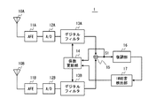
図1は、無線受信装置1の構成例を示すブロック図である。以下では、図1に含まれる各構成要素について説明する。アンテナ素子10A及び10Bは、それぞれ無線信号を受信する。アナログフロントエンド(AFE)11Aは、アンテナ素子10Aによって受信された無線信号に対する帯域制限、中間周波数信号(IF信号)への変換、IF信号増幅を含むアナログ信号処理を行う。AFE11Bは、アンテナ素子10Aによって受信された無線信号に対してAFE11Aと同様のアナログ信号処理を行う。
FIG. 1 is a block diagram illustrating a configuration example of the
A/D変換器12Aは、AFE11Aから供給されるアナログIF信号をデジタルサンプリングし、デジタルIF信号を生成する。同様に、A/D変換器12Bは、AFE11Bから供給されるアナログIF信号をデジタルIF信号に変換する。
The A /
A/D変換器12Aによって生成されたデジタルIF信号は、デジタルフィルタ13Aに送られる。デジタルフィルタ13Aは、トランスバーサル型のデジタルフィルタであり、後述する係数更新部14から供給されるタップ係数を用いてデジタルIF信号に対するフィルタ処理を実行する。同様に、デジタルフィルタ13Bは、A/D変換器12Bによって生成されたデジタルIF信号に対するフィルタ処理を実行する。
The digital IF signal generated by the A /
係数更新部14は、デジタルフィルタ13A及びBのタップ係数群の最適化のためにLMS(Least Mean Square)、NMLS(Normalized MLS)、CMA等の適応アルゴリズムを実行し、タップ係数群を逐次生成してデジタルフィルタ13A及びBに供給する。さらに、係数更新部14は、後述するIM妨害検出部17から供給される制御信号に応じて、適応アルゴリズムに依らずにタップ係数群を更新することができる。係数更新部14の具体的な動作及び構成例については後述する。
The
加算器15は、フィルタ処理された2系統のデジタルIF信号を加算し、デジタル復調処理の対象となる合成信号S1を生成する。
The
復調部16は、合成信号S1から希望信号を復調するためのデジタル復調処理を行う。復調部16によって復調された復調信号は、図示しない後段の信号処理部に供給されるとともに、IM妨害検出部17に供給される。
The
IM妨害検出部17は、復調部16から復調信号を入力し、希望信号に対するIM妨害の発生を検出する。IM妨害検出部17は、IM妨害の発生検出を契機として、係数更新部145に制御信号を出力する。IM妨害検出部17の具体的な動作及び構成例については後述する。
The
続いて以下では、係数更新部14の具体的な動作について説明する。係数更新部14は、加算器15によって合成される合成信号S1を利用し、適応アルゴリズムに従ってデジタルフィルタ13A及びBのタップ係数の更新処理を行う。適応アルゴリズムに基づくタップ係数の更新処理によって、デジタルフィルタ13A及びBは、受信指向性を希望波の到来方向に向たり、妨害波の到来方向にヌル点を形成したりするように動作する。なお、タップ係数の更新は、デジタルフィルタ13A及びBの遅延値も利用して行ってもよい。係数更新部14に適用される適応アルゴリズムは特に限定されるものではなく、係数更新部14は、LMSアルゴリズム、CMA等の公知の適応アルゴリズムを利用すればよい。
Subsequently, a specific operation of the
さらに係数更新部14は、IM妨害の発生検出を示す制御信号がIM妨害検出部17から入力された場合、タップ係数を適応アルゴリズムに依らずに強制的に書き換えるように動作する。このとき、書き換え後のタップ係数は、受信指向性のヌル方向が書き換え前のタップ係数によって得られるヌル方向とは異なる方向となるように選択される。
Furthermore, when a control signal indicating detection of occurrence of IM interference is input from the IM
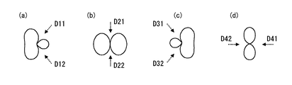
指向性パターン変更の一例を以下に示す。説明容易化のため、デジタルフィルタ13A及びBの初期中心タップ位置がともにN番目あり、アンテナ素子10A及びBのアンテナ間距離を無線信号キャリア周波数の半波長であると仮定する。係数更新部14は、IM妨害が検出される度に、デジタルフィルタ13A及びBの中心タップ位置を以下の組合せ1〜4の間で周期的に変更すればよい。
[組合せ1]フィルタ13A:N番目、 フィルタ13B:N+1番目
[組合せ2]フィルタ13A:N番目、 フィルタ13B:N+2番目
[組合せ3]フィルタ13A:N−1番目、フィルタ13B:N番目
[組合せ4]フィルタ13A:N番目、 フィルタ13B:N番目
図2(a)〜(d)は、タップ中心位置の組合せ1〜4によって得られる指向性パターンを示している。図2(a)〜(d)における点線矢印D11、D12、D21、D22等は、各指向性パターンのヌル方向を表している。なお、デジタルフィルタ13A及びBの単位遅延値(すなわちサンプリング周波数)によってタップ中心位置と指向性パターンとの関係は変化するが、この点は当業者が容易になし得る設計事項であるから、詳細な説明は割愛する。
An example of directivity pattern change is shown below. For ease of explanation, it is assumed that the initial center tap positions of the
[Combination 1]
なお、上述した指向性パターンの変更例が一例に過ぎないことは勿論である。例えば、組合せ1〜4の変更順序を入れ替えてもよい。また、指向性の変化を緩やかにするために、ヌル方向の異なる指向性パターンの総数を5以上として、パターン間の位相の変化を小さくしてもよい。この場合、例えば、上述した"組合せ2"におけるデジタルフィルタ13Bのタップ中心位置を(N+1)+(N+2)とすればよい。また、ヌル方向の異なる指向性パターンの総数を2通り又は3通りとしてもよい。また、指向性パターンの切り替えは、ランダムな順序で行なってもよい。
Of course, the above-described modification of the directivity pattern is only an example. For example, the change order of the
次に、係数更新部14の具体的な構成例について説明する。図3は、係数更新部14の構成例を示すブロック図である。図3の例では、係数更新部14は、更新値算出部140とアキュムレータ141を有する。更新値算出部140は、適応アルゴリズムに従って、係数更新値を算出する。
Next, a specific configuration example of the
アキュムレータ141が有するレジスタ142は、デジタルフィルタ13A及びBに供給されるタップ係数群を保持する。加算器143は、レジスタ142に保持されている値と係数更新値とを加算し、加算結果によってレジスタ142の値を更新する。
A
セレクタ144は、IM妨害検出部17からの制御信号、すなわちIM妨害の検出結果に応じて動作する。具体的に述べると、IM妨害が発生していないとき、セレクタ144は、加算器143からの信号をレジスタ142に与える。一方、IM妨害の発生が検出された場合、セレクタ144は、直接係数値をレジスタ142に与える。ここで、直接係数値とは、適応アルゴリズムに依らずにヌル点方向を変更するよう選択されたタップ係数群である。例えば、上述した指向性パターンの変更例の場合、直接係数値は、組合せ1〜4の中から周期的に選択された値となる。
The
続いて、IM妨害検出部17におけるIM妨害の検出原理とIM妨害検出部17の構成例について説明する。IM妨害検出部17は、復調信号に含まれる希望信号の変調指数を計測し、この計測結果を利用してIM妨害の発生を検出すればよい。上述したように、IM妨害は、2つの妨害波の3次相互変調波(IM3)に起因して発生する。(1)式及び(2)式に示したように、3次相互変調波は、一方の妨害波(例えばf1)の2次高調波成分と他方の妨害波(例えばf2)の基本波成分から発生する。このため、3次相互変調波の変調指数は、元の妨害波f1の変調指数の2倍になる。したがって、3次相互変調波が希望信号の周波数帯域に重なってIM妨害が発生すると、復調信号に含まれる希望信号の変調指数は、本来の値に比べて大きくなっているようにみえる。つまり、IM妨害検出部17は、復調信号に含まれる希望信号の変調指数の大きさを計測することによって、IM妨害の発生を検出できる。
Next, the detection principle of IM interference in the IM
例えば、無線受信装置1がFM放送の受信機である場合、復調信号に含まれる主音声信号(L+R信号)、副音声信号(L−R信号)、パイロット信号、又はその他の多重信号(RDS(Radio Data System)信号、VICS(Vehicle Information and Communication System)信号など)の少なくとも1つの変調指数を計測すればよい。
For example, when the
図4は、変調指数に基づいてIM妨害を検出するためのIM妨害検出部17の構成例を示すブロック図である。図4において、帯域制限フィルタ170は、復調部16から復調信号を受信して帯域制限処理を行う。絶対値検波部171は、帯域制限フィルタ170の出力信号を絶対値検波し、変調指数値を取り出す。絶対値検波部171の出力は、不要な高調波を含む場合がある。このため、平滑化フィルタ172は、不要な高周波成分を取り除く。比較部173は、平滑化フィルタ172の出力に現れる変調指数値と、予め定められた変調指数基準値とを比較する。なお、変調指数基準値は、無線受信装置1の使用地域やサービス内容に応じて、適宜設定すればよい。比較部173は、基準値を超える変調指数が計測された場合に、IM妨害発生を示す制御信号を係数更新部14に対して送信する。
FIG. 4 is a block diagram illustrating a configuration example of the IM
以上に述べたように、本実施の形態にかかる無線受信装置1は、IM妨害の発生検出を契機として、デジタルフィルタ13A及びBに供給されるタップ係数群の少なくとも1つを適応アルゴリズムに拠らずに例外的に更新することとした。つまり、無線受信装置1は、IM妨害の発生検出を契機として、アンテナ素子10A及びBの指向性パターンを変更前とは異なる方向にヌル点を有する他のパターンに変更することができる。これにより、IM妨害をもたらす妨害波の到来方向にヌル点が形成されやすくなる。したがって、無線受信装置1は、IM妨害をもたらす妨害波の到来方向からの信号受信を低減でき、IM妨害の発生を効果的に抑制できる。
As described above, the
<発明の実施の形態2>
本実施の形態にかかる無線受信装置2は、上述した無線受信装置1の動作に加えて、復調信号の品質判定の結果によっても、ヌル点方向を変化させるようアンテナ素子10A及びBの指向性パターンを変更する。
<
The
図5は、無線受信装置2のブロック図である。図5に示す品質判定部28は、復調信号の中に受信品質を劣化させる成分がどの程度含まれているかを判定する。品質判定部28は、S/Nの劣化等の受信品質の劣化を検出した場合に、IM妨害検出部17と同様に、係数更新部14に対して制御信号を出力する。
FIG. 5 is a block diagram of the
IM妨害検出部17又は品質判定部28から出力される制御信号は、OR回路29を経由して係数更新部14に入力される。すなわち、本実施の形態の係数更新部14は、IM妨害の発生及び復調信号の品質劣化の少なくとも一方の条件成立に応じて、アンテナ素子10A及びBの指向性パターンする。実施の形態1で述べたように、指向性パターンの変更は、変更前と比べてヌル点方向が異なる配置となるように行われる。
A control signal output from the IM
続いて、品質判定部28の具体的な構成例について説明する。図6は、品質判定部28の構成例を示すブロック図である。図6において、帯域制限フィルタ280は、復調部16から復調信号を受信して帯域制限処理を行う。絶対値検波部281は、帯域制限フィルタ280の出力信号を絶対値検波し、復調信号に含まれるノイズ成分及び高調波成分を抽出する。絶対値検波により得られる情報には不要な高周波が含まれているため、平滑化フィルタ282は、不要な高周波成分を取り除く。比較部283は、平滑化フィルタ282の出力に現れるノイズ成分値と、予め定められたノイズ成分の基準値とを比較する。なお、ノイズ成分の基準値は、無線受信装置2の使用地域やサービス内容に応じて、適宜設定すればよい。比較部283は、基準値を超えるノイズ成分が計測された場合に、変調信号の品質劣化を示す制御信号を係数更新部14に対して送信する。
Next, a specific configuration example of the
IM妨害検出部17と組み合わせて品質判定部28を設ける利点は以下に述べる通りである。通常、希望波の到来方向は一方向ではないため、IM妨害の検出に応じて指向性パターンを切り替えても希望波が受信不能となる確率は小さい。しかしながら、希望波の到来方向とIM妨害をもたらす妨害波の到来方向とが近接している場合が稀にある。この場合、妨害波の減衰と同時に希望波も減衰するおそれがある。指向性パターンの切り替えによって希望波の減衰が生じると、復調信号のS/Nが劣化する。本実施の形態の品質判定部28は、指向性パターンの切り替えに起因して復調信号の品質劣化が劣化ことを判定し、これを契機として再び指向性パターンを切り替えることができる。つまり、品質判定部28を設けることによって、無線受信装置2は、指向性パターンの切り替えに起因して復調信号の品質劣化が劣化した状態から速やかに脱出することができ、希望波の減衰を抑制することができる。
Advantages of providing the
<発明の実施の形態3>
本実施の形態にかかる無線受信装置3は、上述した無線受信装置2の変形であり、アンテナ素子10A及びBの指向性パターンを切り替える機構が無線受信装置2と異なる。
<Third Embodiment of the Invention>
The
図7は、無線受信装置3の構成例を示すブロック図である。図7に示す無線受信装置3と図6の無線受信装置2との相違点は以下の通りである。図7に示す無線受信装置3では、デジタルフィルタ13Bが省略されている。一方、図7に示す無線受信装置3には、デジタルフィルタ13Aの前段に加算器31、減算器32、スイッチ33が配置されている。係数更新部34は、デジタルフィルタ13Aの出力信号S2を用いてタップ係数群を適応的に更新する。
FIG. 7 is a block diagram illustrating a configuration example of the
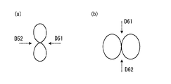
加算器31は、A/D変換器12A及びBから供給される2系統のデジタルIF信号を加算する。一方、減算器32は、A/D変換器12A及びBから供給される2系統のデジタルIF信号を減算する。つまり、加算器31の出力から見たアンテナ素子10A及びBの指向性パターンと、減算器32の出力から見たそれとは異なるパターンとなる。例えば、アンテナ素子10A及びBのアンテナ間距離を無線信号キャリア周波数の半波長とした場合、加算器31の出力から見た指向性パターンは、図8(a)に示すパターンとなる。一方、減算器32の出力から見た指向性パターンは、図8(b)に示すパターンとなる。なお、図8(a)及び(b)に示される点線矢印D51、D52、D61及びD62はヌル点方向を表している。
The
スイッチ33は、加算器31出力及び減算器32出力の一方をデジタルフィルタ13Aに対して選択的に供給する。スイッチ33の切り替え制御のために、IM妨害検出部17及び品質判定部28から出力される制御信号がスイッチ33に入力される。すなわち、スイッチ33の切り替えは、IM妨害検出部17によるIM妨害の発生検出と、品質判定部28による復調信号の品質劣化の検出の少なくとも一方の条件成立に応じて実行される。スイッチ33は、IM妨害検出部17又は品質判定部28から制御信号が入力される度に、加算器31側と減算器32側とを交互に選択するよう動作するとよい。
The switch 33 selectively supplies one of the output from the
上述した無線受信装置1及び2は、アンテナ素子10A及びBによる受信信号をそれぞれ適応処理して合成するため、受信指向性を適応的に制御可能であるがコストが高い。これに対して、無線受信装置3は、一方のデジタルフィルタ13Bを省略し、加算器31又は減算器32による信号合成によって予め指向性を有する合成信号をデジタルフィルタ13Aに入力する。このため、無線受信装置3は、無線受信装置1及び2に比べてコスト低減を図ることができる。なお、図7の構成例では、2つの指向性パターンの間で切り替える例を示したが、3以上の指向性パターンの間で切り替えるよう構成してもよい。
Since the
<発明の実施の形態4>
本実施の形態にかかる無線受信装置4もまた、上述した無線受信装置2の変形であり、アンテナ素子10A及びBの指向性パターンを切り替える機構が無線受信装置2と異なる。
<
The
図9は、無線受信装置4の構成例を示すブロック図である。図9に示す無線受信装置4と図6の無線受信装置2との相違点は以下の通りである。図9に示す無線受信装置4では、AFE11B、A/D変換器12B及びデジタルフィルタ13Bが省略されている。一方、図9に示す無線受信装置4には、AFE11Aの前段に加算器41、減算器42、スイッチ43が配置されている。
FIG. 9 is a block diagram illustrating a configuration example of the
加算器41は、アンテナ素子10A及びBによって受信された2系統の受信信号(アナログRF信号)を加算する。一方、減算器42は、2系統の受信信号(アナログRF信号)を減算する。つまり、発明の実施の形態3に示した無線受信装置3と同様に、加算器41の出力から見たアンテナ素子10A及びBの指向性パターンと、減算器42の出力から見たそれとは異なるパターンとなる。
The
スイッチ43は、加算器41出力及び減算器42出力の一方をAFE11Aに対して選択的に供給する。スイッチ43の切り替え制御のために、IM妨害検出部17及び品質判定部28から出力される制御信号がスイッチ43に入力される。すなわち、スイッチ43の切り替えは、IM妨害検出部17によるIM妨害の発生検出と、品質判定部28による復調信号の品質劣化の検出の少なくとも一方の条件成立に応じて実行される。スイッチ43は、IM妨害検出部17又は品質判定部28から制御信号が入力される度に、加算器41側と減算器42側とを交互に選択するよう動作するとよい。
The
本実施の形態にかかる無線受信装置4は、AFE11B、A/D変換器12B及びデジタルフィルタ13Bを省略し、加算器41又は減算器42による信号合成によって予め指向性を有する合成信号をAFE11Aに入力する。このため、無線受信装置4は、上述した無線受信装置1乃至3に比べてコスト低減を図ることができる。なお、図9の構成例では、2つの指向性パターンの間で切り替える例を示したが、3以上の指向性パターンの間で切り替えるよう構成してもよい。
The
<発明の実施の形態5>
本実施の形態にかかる無線受信装置5は、上述した無線受信装置4の変形である。無線受信装置5は、無線受信装置4と比べて、IM妨害検出の原理とIM妨害検出のための構成が異なる。
<
The
図10は、無線受信装置5のブロック図である。IM妨害検出部57は、AFE51Aから供給される2系統のアナログIF信号を元にIF妨害の発生を検出する。
FIG. 10 is a block diagram of the
AFE51Aの構成例を図11に示す。RFアンプ510、ミキサ511及びIFアンプ513は、A/D変換器12に供給されるアナログIF信号を生成するための構成要素である。ミキサ511は、RFアンプ510によって増幅されたアナログRF信号を局部発振器512から供給される局部発振信号と乗算し、アナログIF信号に変換する。
A configuration example of the
図11に示すAFE51Aは、上述したミキサ511とは別にもう1つのミキサ514を有する。ミキサ511と同様に、ミキサ514は、アナログRF信号をアナログIF信号に変換する。しかしながら、ミキサ514は、ミキサ511に比べて出力信号に相互変調歪みを生じさせ易い歪み特性を有する。
An
2つのミキサ511及び514の歪み特性の違いのために、これら2つのミキサによって生成される2つのアナログIF信号に含まれる3次相互変調歪み成分の信号電力は相違する。つまり、歪み特性の悪いミキサ514の出力信号には、ミキサ511の出力信号に比べて大きな3次相互変調歪みが発生する。このため、IM妨害検出部57は、ミキサ511及び514によって生成される2系統のアナログIF信号を入力し、これら2信号に対する帯域制限処理を行なった後に電力差を計測し、電力差が予め定められた基準値より大きくなることによってIM妨害の発生を検出することができる。
Due to the difference in distortion characteristics between the two
なお、上述した発明の実施の形態1〜5では、2つのアンテナ素子10A及びBを用いて無線信号を受信する構成について説明した。しかしながら、3以上のアンテナ素子を配置し、3系統以上の受信信号に対する演算処理によって受信指向性を調整するよう無線受信装置1〜5を変形してもよい。
In the first to fifth embodiments of the present invention described above, the configuration for receiving a radio signal using the two
また、上述した発明の実施の形態1〜5に示したデジタルフィルタ13A並びに13B、係数更新部14並びに34、復調部16、IM妨害検出部17並びに57、品質判定部28、及びOR回路29等のデジタル信号処理に関する構成要素は、DSP(Digital Signal Processor)等のコンピュータによって実現してもよい。
Also, the
さらに、本発明は上述した実施の形態のみに限定されるものではなく、既に述べた本発明の要旨を逸脱しない範囲において種々の変更が可能であることは勿論である。 Furthermore, the present invention is not limited to the above-described embodiments, and various modifications can be made without departing from the gist of the present invention described above.
1、2、3、4 無線受信装置
10A、10B アンテナ素子
11A、11B アナログフロントエンド(AFE)
12A、12B A/D変換器
13A、13B デジタルフィルタ
14 係数更新部
15 加算器
16 復調部
17 IM妨害検出部
28 品質判定部
29 OR回路
31 加算器
32 減算器
33 スイッチ
41 加算器
42 減算器
43 スイッチ
140 更新値算出部
141 アキュムレータ
142 レジスタ
143 加算器
144 セレクタ
170 帯域制限フィルタ
171 絶対値検波部
172 平滑化フィルタ
173 比較部
280 帯域制限フィルタ
281 絶対値検波部
282 平滑化フィルタ
283 比較部
510 RFアンプ
511、514 ミキサ
512 局部発振器
513 IFアンプ
1, 2, 3, 4
12A, 12B A /
Claims (8)
前記検出部による相互変調妨害の発生検出を契機として、前記複数のアンテナ素子の指向性パターンを変更前とは異なる方向にヌル点を有する他のパターンに変更する指向性変更手段と、
前記合成信号をアナログ信号処理するアナログ信号処理部と、を備え、
前記アナログ信号処理部は、
前記合成信号を増幅する増幅部と、
増幅後の前記合成信号を局部発振信号と混合して第1の中間周波数信号を生成する第1のミキサと、
前記第1のミキサに比べて前記受信信号に相互変調歪みを生じさせ易い歪み特性を有し、増幅後の前記合成信号を前記局部発振信号と混合して第2の中間周波数信号を生成する第2のミキサと、を有し、
前記検出部は、前記第1及び第2の中間周波数信号の信号振幅を比較することによって前記相互変調妨害の発生を検出する、
無線受信装置。 A detection unit for detecting occurrence of intermodulation interference for a desired signal demodulated from a composite signal of a plurality of reception signals induced in each of a plurality of antenna elements or one reception signal included in the plurality of reception signals;
Directivity changing means for changing the directivity pattern of the plurality of antenna elements to another pattern having a null point in a direction different from that before the change, triggered by detection of occurrence of intermodulation interference by the detection unit,
An analog signal processing unit that performs analog signal processing on the combined signal,
The analog signal processor is
An amplifying unit for amplifying the combined signal;
A first mixer that mixes the combined signal after amplification with a local oscillation signal to generate a first intermediate frequency signal;
Compared to the first mixer, the received signal has a distortion characteristic that easily causes intermodulation distortion, and the synthesized signal after amplification is mixed with the local oscillation signal to generate a second intermediate frequency signal. 2 mixers,
The detector detects the occurrence of the intermodulation interference by comparing signal amplitudes of the first and second intermediate frequency signals;
Wireless receiver.
前記指向性変更手段は、前記相互変調妨害の発生と前記希望信号の品質劣化の少なくとも一方の検出を契機として前記指向性パターンを変更する、請求項1又は2に記載の無線受信装置。 A quality determination unit for detecting quality degradation of the desired signal;
The directional changing means, wherein changing the directivity pattern in response to at least one of the detection of the quality degradation occurs when the desired signal of the intermodulation interference, radio receiving apparatus according to claim 1 or 2.
前記アナログ信号処理が行なわれた前記複数の受信信号をサンプリングすることにより複数のデジタル信号を生成するA/D変換部と、
前記複数のデジタル信号の振幅及び位相を調整可能な複数のデジタルフィルタと、
前記複数のデジタルフィルタによってフィルタ処理された前記複数のデジタル信号を合成する信号合成部と、
前記複数のデジタルフィルタのタップ係数群を更新する係数更新部と、
を備え、
前記係数更新部は、適応アルゴリズムに従って前記タップ係数群を更新するとともに、希望信号に対する相互変調妨害の発生検出を契機として、前記タップ係数群の少なくとも1つを前記適応アルゴリズムに拠らずに例外的に更新する、無線受信装置。 An analog signal processing unit for analog signal processing of a plurality of received signals received by a plurality of antenna elements;
An A / D converter that generates a plurality of digital signals by sampling the plurality of received signals subjected to the analog signal processing;
A plurality of digital filters capable of adjusting the amplitude and phase of the plurality of digital signals;
A signal synthesizer for synthesizing the plurality of digital signals filtered by the plurality of digital filters;
A coefficient updating unit for updating a tap coefficient group of the plurality of digital filters;
With
The coefficient updating unit updates the tap coefficient group according to an adaptive algorithm, and triggers detection of occurrence of intermodulation interference with respect to a desired signal, so that at least one of the tap coefficient groups does not depend on the adaptive algorithm. A wireless receiver that is updated to
前記ヌル点が互いに異なる方向に配置されるよう定められた、前記複数のデジタルフィルタそれぞれの中心タップ位置の複数の組合せを保持し、Holding a plurality of combinations of center tap positions of each of the plurality of digital filters, the null points being determined to be arranged in different directions;
前記相互変調妨害の発生検出の度に、前記複数の組合せの内から選択する組合せを変更して、前記少なくとも1つの中心タップ位置を変更する、Each time the occurrence of the intermodulation interference is detected, a combination selected from the plurality of combinations is changed to change the at least one center tap position.
請求項6に記載の無線受信装置。The wireless receiver according to claim 6.
前記相互変調妨害の発生検出を契機として、前記複数のアンテナ素子の指向性パターンを変更前とは異なる方向にヌル点を有する他のパターンに変更するステップ(b)と、
前記合成信号をアナログ信号処理するステップ(c)と、を備え、
前記ステップ(c)にて、
前記合成信号を増幅し、
第1のミキサを用いて、増幅後の前記合成信号を局部発振信号と混合して第1の中間周波数信号を生成し、
前記第1のミキサに比べて前記受信信号に相互変調歪みを生じさせ易い歪み特性を有する第2のミキサを用いて、増幅後の前記合成信号を前記局部発振信号と混合して第2の中間周波数信号を生成し、
前記ステップ(a)にて、前記第1及び第2の中間周波数信号の信号振幅を比較することによって前記相互変調妨害の発生を検出する、
無線受信方法。 Detecting the occurrence of intermodulation interference for a desired signal demodulated from a composite signal of a plurality of reception signals induced in each of a plurality of antenna elements or one reception signal included in the plurality of reception signals; ,
(B) changing the directivity pattern of the plurality of antenna elements to another pattern having a null point in a direction different from that before the change, triggered by the occurrence detection of the intermodulation interference;
And (c) performing analog signal processing on the synthesized signal.
In step (c)
Amplifying the combined signal;
Using the first mixer, the synthesized signal after amplification is mixed with a local oscillation signal to generate a first intermediate frequency signal,
Using the second mixer having a distortion characteristic that tends to cause intermodulation distortion in the received signal as compared with the first mixer, the amplified composite signal is mixed with the local oscillation signal to obtain a second intermediate signal. Generate a frequency signal,
Detecting the occurrence of the intermodulation interference in the step (a) by comparing signal amplitudes of the first and second intermediate frequency signals;
Wireless reception method.
Priority Applications (2)
| Application Number | Priority Date | Filing Date | Title |
|---|---|---|---|
| JP2008200593A JP5117316B2 (en) | 2008-08-04 | 2008-08-04 | Radio receiving apparatus and radio receiving method |
| US12/461,010 US20100029237A1 (en) | 2008-08-04 | 2009-07-29 | Radio receiving apparatus and radio receiving method |
Applications Claiming Priority (1)
| Application Number | Priority Date | Filing Date | Title |
|---|---|---|---|
| JP2008200593A JP5117316B2 (en) | 2008-08-04 | 2008-08-04 | Radio receiving apparatus and radio receiving method |
Publications (2)
| Publication Number | Publication Date |
|---|---|
| JP2010041284A JP2010041284A (en) | 2010-02-18 |
| JP5117316B2 true JP5117316B2 (en) | 2013-01-16 |
Family
ID=41608868
Family Applications (1)
| Application Number | Title | Priority Date | Filing Date |
|---|---|---|---|
| JP2008200593A Expired - Fee Related JP5117316B2 (en) | 2008-08-04 | 2008-08-04 | Radio receiving apparatus and radio receiving method |
Country Status (2)
| Country | Link |
|---|---|
| US (1) | US20100029237A1 (en) |
| JP (1) | JP5117316B2 (en) |
Families Citing this family (6)
| Publication number | Priority date | Publication date | Assignee | Title |
|---|---|---|---|---|
| US8565744B2 (en) * | 2006-10-31 | 2013-10-22 | Intel Corporation | Vertical handover composite quality measures |
| CN103733664B (en) | 2011-07-11 | 2017-10-24 | 康普技术有限责任公司 | Method and apparatus for managing a distributed antenna system |
| DE202012013601U1 (en) | 2011-09-15 | 2018-04-24 | Andrew Wireless Systems Gmbh | Configuration subsystem for telecommunication systems |
| ES2572954T3 (en) | 2011-09-16 | 2016-06-03 | Andrew Wireless Systems Gmbh | Integrated intermodulation detection subsystem for telecommunications systems |
| US9894623B2 (en) | 2012-09-14 | 2018-02-13 | Andrew Wireless Systems Gmbh | Uplink path integrity detection in distributed antenna systems |
| EP2904831B1 (en) | 2012-10-05 | 2017-10-04 | Andrew Wireless Systems GmbH | Capacity optimization sub-system for distributed antenna system |
Family Cites Families (22)
| Publication number | Priority date | Publication date | Assignee | Title |
|---|---|---|---|---|
| US5697084A (en) * | 1994-09-16 | 1997-12-09 | Bose Corporation | Reducing multipath fading using adaptive filtering |
| US5953367A (en) * | 1995-08-09 | 1999-09-14 | Magellan Corporation | Spread spectrum receiver using a pseudo-random noise code for ranging applications in a way that reduces errors when a multipath signal is present |
| US5742258A (en) * | 1995-08-22 | 1998-04-21 | Hazeltine Corporation | Low intermodulation electromagnetic feed cellular antennas |
| US5710995A (en) * | 1997-01-16 | 1998-01-20 | Ford Motor Company | Adaptive antenna receiver |
| JP3768350B2 (en) * | 1998-03-30 | 2006-04-19 | 松下電器産業株式会社 | Wireless receiving apparatus and method |
| JP3919342B2 (en) * | 1998-07-14 | 2007-05-23 | 株式会社ケンウッド | Wideband digital receiver |
| US6449469B1 (en) * | 1999-03-01 | 2002-09-10 | Visteon Global Technologies, Inc. | Switched directional antenna for automotive radio receivers |
| US6704557B1 (en) * | 1999-04-22 | 2004-03-09 | Lucent Technologies Inc. | System and method for protecting a receiver from jamming interference |
| JP3576880B2 (en) * | 1999-09-09 | 2004-10-13 | 日本電気株式会社 | Automatic modulation system identification device and automatic modulation system identification method |
| JP2001177460A (en) * | 1999-12-17 | 2001-06-29 | Matsushita Electric Ind Co Ltd | Wireless receiving apparatus and wireless receiving method |
| EP1215822A1 (en) * | 2000-12-18 | 2002-06-19 | Nokia Corporation | Radio transmission device and method for aligning parameters thereof |
| US7346134B2 (en) * | 2001-05-15 | 2008-03-18 | Finesse Wireless, Inc. | Radio receiver |
| US6859641B2 (en) * | 2001-06-21 | 2005-02-22 | Applied Signal Technology, Inc. | Adaptive canceller for frequency reuse systems |
| JP2003110476A (en) * | 2001-09-27 | 2003-04-11 | Matsushita Electric Ind Co Ltd | Wireless receiving apparatus and directional receiving method |
| DE10304431A1 (en) * | 2003-02-04 | 2004-08-05 | Lindenmeier, Heinz, Prof. Dr.-Ing. | Scanning antenna diversity system is used for frequency modulated audio wireless signals in a road vehicle |
| US6946992B2 (en) * | 2003-12-18 | 2005-09-20 | The Boeing Company | Multibeam phased array antenna |
| JP4439280B2 (en) * | 2004-02-09 | 2010-03-24 | 株式会社東芝 | DBF antenna system |
| US7324616B2 (en) * | 2004-03-01 | 2008-01-29 | Motorola, Inc. | Low cost and high performance narrowband interference cancellation system |
| JP4524147B2 (en) * | 2004-06-30 | 2010-08-11 | 京セラ株式会社 | COMMUNICATION DEVICE, CALIBRATION METHOD, AND PROGRAM |
| US7817967B2 (en) * | 2005-06-21 | 2010-10-19 | Atc Technologies, Llc | Communications systems including adaptive antenna systems and methods for inter-system and intra-system interference reduction |
| US20070082617A1 (en) * | 2005-10-11 | 2007-04-12 | Crestcom, Inc. | Transceiver with isolation-filter compensation and method therefor |
| US7622820B1 (en) * | 2007-03-16 | 2009-11-24 | Aleksandar Prodic | Switch-mode power supply (SMPS) with auto-tuning using limit-cycle oscillation response evaluation |
-
2008
- 2008-08-04 JP JP2008200593A patent/JP5117316B2/en not_active Expired - Fee Related
-
2009
- 2009-07-29 US US12/461,010 patent/US20100029237A1/en not_active Abandoned
Also Published As
| Publication number | Publication date |
|---|---|
| JP2010041284A (en) | 2010-02-18 |
| US20100029237A1 (en) | 2010-02-04 |
Similar Documents
| Publication | Publication Date | Title |
|---|---|---|
| JP5117316B2 (en) | Radio receiving apparatus and radio receiving method | |
| JPWO2007105796A1 (en) | Adaptive control device | |
| JP5766369B2 (en) | Diversity receiving apparatus and diversity receiving method | |
| JP2010183171A (en) | Receiver | |
| JP4693462B2 (en) | Diversity receiving apparatus and method | |
| WO2006106788A1 (en) | Reducing apparatus and method, and receiving apparatus | |
| JP2010004451A (en) | Noise reduction device for on-vehicle radio device | |
| JP4361089B2 (en) | Phase synthesis diversity receiver | |
| JP4892280B2 (en) | Receiving apparatus and adaptive algorithm control method | |
| JP3385996B2 (en) | Diversity receiver | |
| JP4378263B2 (en) | Receiver | |
| JP3668420B2 (en) | Array antenna control apparatus and control method | |
| JP2020061643A (en) | Receiving device, receiving system, and receiving method | |
| JP2006177671A (en) | Interference canceller | |
| JP5190536B2 (en) | Array antenna device | |
| JP4907435B2 (en) | Array antenna apparatus and control method thereof, radio receiver, integrated circuit, program, and recording medium | |
| JP2010098413A (en) | Interference noise reducing device | |
| JP4769182B2 (en) | Diversity receiver | |
| JP2003046485A (en) | Interference wave suppression system | |
| JP4627094B2 (en) | Diversity receiver | |
| JP4523968B2 (en) | Wireless receiver | |
| JP2006229976A (en) | Digital signal receiver for fading correction | |
| JP2018082289A (en) | Wireless communication apparatus, interference suppression circuit, and interference suppression method | |
| JP2015109594A (en) | Diversity receiver and diversity reception method | |
| JP2005101916A (en) | Antenna equipment for terrestrial digital TV broadcasting |
Legal Events
| Date | Code | Title | Description |
|---|---|---|---|
| A621 | Written request for application examination |
Free format text: JAPANESE INTERMEDIATE CODE: A621 Effective date: 20110701 |
|
| A977 | Report on retrieval |
Free format text: JAPANESE INTERMEDIATE CODE: A971007 Effective date: 20120608 |
|
| A131 | Notification of reasons for refusal |
Free format text: JAPANESE INTERMEDIATE CODE: A131 Effective date: 20120612 |
|
| A521 | Written amendment |
Free format text: JAPANESE INTERMEDIATE CODE: A523 Effective date: 20120809 |
|
| TRDD | Decision of grant or rejection written | ||
| A01 | Written decision to grant a patent or to grant a registration (utility model) |
Free format text: JAPANESE INTERMEDIATE CODE: A01 Effective date: 20121002 |
|
| A01 | Written decision to grant a patent or to grant a registration (utility model) |
Free format text: JAPANESE INTERMEDIATE CODE: A01 |
|
| A61 | First payment of annual fees (during grant procedure) |
Free format text: JAPANESE INTERMEDIATE CODE: A61 Effective date: 20121017 |
|
| R150 | Certificate of patent or registration of utility model |
Free format text: JAPANESE INTERMEDIATE CODE: R150 |
|
| FPAY | Renewal fee payment (event date is renewal date of database) |
Free format text: PAYMENT UNTIL: 20151026 Year of fee payment: 3 |
|
| S531 | Written request for registration of change of domicile |
Free format text: JAPANESE INTERMEDIATE CODE: R313531 |
|
| R350 | Written notification of registration of transfer |
Free format text: JAPANESE INTERMEDIATE CODE: R350 |
|
| LAPS | Cancellation because of no payment of annual fees |