JP5117510B2 - Generator assembly - Google Patents
Generator assembly Download PDFInfo
- Publication number
- JP5117510B2 JP5117510B2 JP2009549435A JP2009549435A JP5117510B2 JP 5117510 B2 JP5117510 B2 JP 5117510B2 JP 2009549435 A JP2009549435 A JP 2009549435A JP 2009549435 A JP2009549435 A JP 2009549435A JP 5117510 B2 JP5117510 B2 JP 5117510B2
- Authority
- JP
- Japan
- Prior art keywords
- voltage
- generator
- converter
- power
- generator assembly
- Prior art date
- Legal status (The legal status is an assumption and is not a legal conclusion. Google has not performed a legal analysis and makes no representation as to the accuracy of the status listed.)
- Active
Links
Images

Classifications
-
- H—ELECTRICITY
- H02—GENERATION; CONVERSION OR DISTRIBUTION OF ELECTRIC POWER
- H02P—CONTROL OR REGULATION OF ELECTRIC MOTORS, ELECTRIC GENERATORS OR DYNAMO-ELECTRIC CONVERTERS; CONTROLLING TRANSFORMERS, REACTORS OR CHOKE COILS
- H02P9/00—Arrangements for controlling electric generators for the purpose of obtaining a desired output
- H02P9/14—Arrangements for controlling electric generators for the purpose of obtaining a desired output by variation of field
- H02P9/26—Arrangements for controlling electric generators for the purpose of obtaining a desired output by variation of field using discharge tubes or semiconductor devices
-
- H—ELECTRICITY
- H02—GENERATION; CONVERSION OR DISTRIBUTION OF ELECTRIC POWER
- H02P—CONTROL OR REGULATION OF ELECTRIC MOTORS, ELECTRIC GENERATORS OR DYNAMO-ELECTRIC CONVERTERS; CONTROLLING TRANSFORMERS, REACTORS OR CHOKE COILS
- H02P9/00—Arrangements for controlling electric generators for the purpose of obtaining a desired output
- H02P9/14—Arrangements for controlling electric generators for the purpose of obtaining a desired output by variation of field
- H02P9/26—Arrangements for controlling electric generators for the purpose of obtaining a desired output by variation of field using discharge tubes or semiconductor devices
- H02P9/30—Arrangements for controlling electric generators for the purpose of obtaining a desired output by variation of field using discharge tubes or semiconductor devices using semiconductor devices
- H02P9/305—Arrangements for controlling electric generators for the purpose of obtaining a desired output by variation of field using discharge tubes or semiconductor devices using semiconductor devices controlling voltage
-
- B—PERFORMING OPERATIONS; TRANSPORTING
- B60—VEHICLES IN GENERAL
- B60L—PROPULSION OF ELECTRICALLY-PROPELLED VEHICLES; SUPPLYING ELECTRIC POWER FOR AUXILIARY EQUIPMENT OF ELECTRICALLY-PROPELLED VEHICLES; ELECTRODYNAMIC BRAKE SYSTEMS FOR VEHICLES IN GENERAL; MAGNETIC SUSPENSION OR LEVITATION FOR VEHICLES; MONITORING OPERATING VARIABLES OF ELECTRICALLY-PROPELLED VEHICLES; ELECTRIC SAFETY DEVICES FOR ELECTRICALLY-PROPELLED VEHICLES
- B60L50/00—Electric propulsion with power supplied within the vehicle
- B60L50/50—Electric propulsion with power supplied within the vehicle using propulsion power supplied by batteries or fuel cells
- B60L50/60—Electric propulsion with power supplied within the vehicle using propulsion power supplied by batteries or fuel cells using power supplied by batteries
- B60L50/61—Electric propulsion with power supplied within the vehicle using propulsion power supplied by batteries or fuel cells using power supplied by batteries by batteries charged by engine-driven generators, e.g. series hybrid electric vehicles
-
- B—PERFORMING OPERATIONS; TRANSPORTING
- B60—VEHICLES IN GENERAL
- B60L—PROPULSION OF ELECTRICALLY-PROPELLED VEHICLES; SUPPLYING ELECTRIC POWER FOR AUXILIARY EQUIPMENT OF ELECTRICALLY-PROPELLED VEHICLES; ELECTRODYNAMIC BRAKE SYSTEMS FOR VEHICLES IN GENERAL; MAGNETIC SUSPENSION OR LEVITATION FOR VEHICLES; MONITORING OPERATING VARIABLES OF ELECTRICALLY-PROPELLED VEHICLES; ELECTRIC SAFETY DEVICES FOR ELECTRICALLY-PROPELLED VEHICLES
- B60L2210/00—Converter types
- B60L2210/20—AC to AC converters
-
- B—PERFORMING OPERATIONS; TRANSPORTING
- B60—VEHICLES IN GENERAL
- B60L—PROPULSION OF ELECTRICALLY-PROPELLED VEHICLES; SUPPLYING ELECTRIC POWER FOR AUXILIARY EQUIPMENT OF ELECTRICALLY-PROPELLED VEHICLES; ELECTRODYNAMIC BRAKE SYSTEMS FOR VEHICLES IN GENERAL; MAGNETIC SUSPENSION OR LEVITATION FOR VEHICLES; MONITORING OPERATING VARIABLES OF ELECTRICALLY-PROPELLED VEHICLES; ELECTRIC SAFETY DEVICES FOR ELECTRICALLY-PROPELLED VEHICLES
- B60L2240/00—Control parameters of input or output; Target parameters
- B60L2240/40—Drive Train control parameters
- B60L2240/52—Drive Train control parameters related to converters
- B60L2240/527—Voltage
-
- H—ELECTRICITY
- H02—GENERATION; CONVERSION OR DISTRIBUTION OF ELECTRIC POWER
- H02M—APPARATUS FOR CONVERSION BETWEEN AC AND AC, BETWEEN AC AND DC, OR BETWEEN DC AND DC, AND FOR USE WITH MAINS OR SIMILAR POWER SUPPLY SYSTEMS; CONVERSION OF DC OR AC INPUT POWER INTO SURGE OUTPUT POWER; CONTROL OR REGULATION THEREOF
- H02M5/00—Conversion of AC power input into AC power output, e.g. for change of voltage, for change of frequency, for change of number of phases
- H02M5/40—Conversion of AC power input into AC power output, e.g. for change of voltage, for change of frequency, for change of number of phases with intermediate conversion into DC
- H02M5/42—Conversion of AC power input into AC power output, e.g. for change of voltage, for change of frequency, for change of number of phases with intermediate conversion into DC by static converters
- H02M5/44—Conversion of AC power input into AC power output, e.g. for change of voltage, for change of frequency, for change of number of phases with intermediate conversion into DC by static converters using discharge tubes or semiconductor devices to convert the intermediate DC into AC
- H02M5/453—Conversion of AC power input into AC power output, e.g. for change of voltage, for change of frequency, for change of number of phases with intermediate conversion into DC by static converters using discharge tubes or semiconductor devices to convert the intermediate DC into AC using devices of a triode or transistor type requiring continuous application of a control signal
- H02M5/458—Conversion of AC power input into AC power output, e.g. for change of voltage, for change of frequency, for change of number of phases with intermediate conversion into DC by static converters using discharge tubes or semiconductor devices to convert the intermediate DC into AC using devices of a triode or transistor type requiring continuous application of a control signal using semiconductor devices only
- H02M5/4585—Conversion of AC power input into AC power output, e.g. for change of voltage, for change of frequency, for change of number of phases with intermediate conversion into DC by static converters using discharge tubes or semiconductor devices to convert the intermediate DC into AC using devices of a triode or transistor type requiring continuous application of a control signal using semiconductor devices only having a rectifier with controlled elements
-
- Y—GENERAL TAGGING OF NEW TECHNOLOGICAL DEVELOPMENTS; GENERAL TAGGING OF CROSS-SECTIONAL TECHNOLOGIES SPANNING OVER SEVERAL SECTIONS OF THE IPC; TECHNICAL SUBJECTS COVERED BY FORMER USPC CROSS-REFERENCE ART COLLECTIONS [XRACs] AND DIGESTS
- Y02—TECHNOLOGIES OR APPLICATIONS FOR MITIGATION OR ADAPTATION AGAINST CLIMATE CHANGE
- Y02T—CLIMATE CHANGE MITIGATION TECHNOLOGIES RELATED TO TRANSPORTATION
- Y02T10/00—Road transport of goods or passengers
- Y02T10/60—Other road transportation technologies with climate change mitigation effect
- Y02T10/62—Hybrid vehicles
-
- Y—GENERAL TAGGING OF NEW TECHNOLOGICAL DEVELOPMENTS; GENERAL TAGGING OF CROSS-SECTIONAL TECHNOLOGIES SPANNING OVER SEVERAL SECTIONS OF THE IPC; TECHNICAL SUBJECTS COVERED BY FORMER USPC CROSS-REFERENCE ART COLLECTIONS [XRACs] AND DIGESTS
- Y02—TECHNOLOGIES OR APPLICATIONS FOR MITIGATION OR ADAPTATION AGAINST CLIMATE CHANGE
- Y02T—CLIMATE CHANGE MITIGATION TECHNOLOGIES RELATED TO TRANSPORTATION
- Y02T10/00—Road transport of goods or passengers
- Y02T10/60—Other road transportation technologies with climate change mitigation effect
- Y02T10/64—Electric machine technologies in electromobility
-
- Y—GENERAL TAGGING OF NEW TECHNOLOGICAL DEVELOPMENTS; GENERAL TAGGING OF CROSS-SECTIONAL TECHNOLOGIES SPANNING OVER SEVERAL SECTIONS OF THE IPC; TECHNICAL SUBJECTS COVERED BY FORMER USPC CROSS-REFERENCE ART COLLECTIONS [XRACs] AND DIGESTS
- Y02—TECHNOLOGIES OR APPLICATIONS FOR MITIGATION OR ADAPTATION AGAINST CLIMATE CHANGE
- Y02T—CLIMATE CHANGE MITIGATION TECHNOLOGIES RELATED TO TRANSPORTATION
- Y02T10/00—Road transport of goods or passengers
- Y02T10/60—Other road transportation technologies with climate change mitigation effect
- Y02T10/70—Energy storage systems for electromobility, e.g. batteries
-
- Y—GENERAL TAGGING OF NEW TECHNOLOGICAL DEVELOPMENTS; GENERAL TAGGING OF CROSS-SECTIONAL TECHNOLOGIES SPANNING OVER SEVERAL SECTIONS OF THE IPC; TECHNICAL SUBJECTS COVERED BY FORMER USPC CROSS-REFERENCE ART COLLECTIONS [XRACs] AND DIGESTS
- Y02—TECHNOLOGIES OR APPLICATIONS FOR MITIGATION OR ADAPTATION AGAINST CLIMATE CHANGE
- Y02T—CLIMATE CHANGE MITIGATION TECHNOLOGIES RELATED TO TRANSPORTATION
- Y02T10/00—Road transport of goods or passengers
- Y02T10/60—Other road transportation technologies with climate change mitigation effect
- Y02T10/7072—Electromobility specific charging systems or methods for batteries, ultracapacitors, supercapacitors or double-layer capacitors
-
- Y—GENERAL TAGGING OF NEW TECHNOLOGICAL DEVELOPMENTS; GENERAL TAGGING OF CROSS-SECTIONAL TECHNOLOGIES SPANNING OVER SEVERAL SECTIONS OF THE IPC; TECHNICAL SUBJECTS COVERED BY FORMER USPC CROSS-REFERENCE ART COLLECTIONS [XRACs] AND DIGESTS
- Y02—TECHNOLOGIES OR APPLICATIONS FOR MITIGATION OR ADAPTATION AGAINST CLIMATE CHANGE
- Y02T—CLIMATE CHANGE MITIGATION TECHNOLOGIES RELATED TO TRANSPORTATION
- Y02T10/00—Road transport of goods or passengers
- Y02T10/60—Other road transportation technologies with climate change mitigation effect
- Y02T10/72—Electric energy management in electromobility
Landscapes
- Engineering & Computer Science (AREA)
- Power Engineering (AREA)
- Life Sciences & Earth Sciences (AREA)
- Sustainable Development (AREA)
- Sustainable Energy (AREA)
- Transportation (AREA)
- Mechanical Engineering (AREA)
- Control Of Eletrric Generators (AREA)
Description
本発明は、独立請求項1に記載の発電機アセンブリに関するものである。 The invention relates to a generator assembly according to the independent claim 1.
公知の発電機アセンブリは、ディーゼルエンジンなどの可変速原動機によって駆動する交流発電機を有し、これによって生成された電気は周波数コンバータを経て負荷に供給される。周波数コンバータは、交流発電機によってダイオードブリッジを経て給電される直流電圧中間回路を有する。原動機の回転速度に応じて交流発電機の回転速度が変化すると、周波数コンバータの直流電圧中間回路の電圧も変化しやすくなる。ゆえに、発電機アセンブリには直流電圧中間回路の電圧を一定に保つため昇圧チョッパが備えられている。この発電機アセンブリの問題点は、直流電圧中間回路の電圧を上記の方法で一定に保つことがかなり困難なことにある。 Known generator assemblies have an alternator driven by a variable speed prime mover, such as a diesel engine, and the electricity generated thereby is supplied to a load via a frequency converter. The frequency converter has a DC voltage intermediate circuit that is fed through a diode bridge by an AC generator. When the rotational speed of the alternator changes according to the rotational speed of the prime mover, the voltage of the DC voltage intermediate circuit of the frequency converter also tends to change. Therefore, the generator assembly is provided with a boost chopper in order to keep the voltage of the DC voltage intermediate circuit constant. The problem with this generator assembly is that it is quite difficult to keep the voltage of the DC voltage intermediate circuit constant in the manner described above.
本発明の目的は、次のような交流発電機を有する発電機アセンブリを提供することである。すなわち、このアセンブリは、交流発電機が可変速原動機によって駆動されるときであってもチョッパなしで直流電圧中間回路の電圧が実質的に一定に保たれるものである。本発明の目的は、独立請求項の記載事項によって特徴付けられる発電機アセンブリによって達成される。本発明の好ましい実施態様は従属請求項に開示されている。 An object of the present invention is to provide a generator assembly having the following AC generator. That is, this assembly is such that the voltage of the DC voltage intermediate circuit is kept substantially constant without a chopper even when the AC generator is driven by a variable speed prime mover. The object of the invention is achieved by a generator assembly characterized by what is stated in the independent claims. Preferred embodiments of the invention are disclosed in the dependent claims.
本発明は、交流発電機の磁化はその出力電圧に基づいて調整され、交流発電機の電力は発電機のAC結合部を通過する電流のトルク依存成分を変えることによって調整されるという着想を基盤としている。 The invention is based on the idea that the magnetization of an alternator is adjusted based on its output voltage and the alternator power is adjusted by changing the torque-dependent component of the current passing through the AC coupling of the generator. It is said.
本発明の発電機アセンブリは、交流発電機で給電される第1のコンバータ部によって生成される直流電圧はチョッパなしで実質的に一定に保たれるという利点を有する。 The generator assembly of the present invention has the advantage that the DC voltage generated by the first converter section fed by the AC generator is kept substantially constant without a chopper.
以下において、添付図面を参照して本発明を望ましい実施例と関連してより詳細に説明する。すなわち、
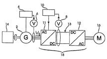
図1の発電機アセンブリには、原動機14、交流発電機2を有する発電手段、周波数コンバータ18および電気モータ16が含まれる。原動機14は交流発電機2の軸と連結され、原動機14と交流発電機2の間で機械的動力を伝動する。原動機14は、例えば可変速度ディーゼルエンジンのような可変速原動機であってよい。
The generator assembly of FIG. 1 includes a prime mover 14, a generator means having an AC generator 2, a
発電手段は原動機14から得られる機械的動力を交流電力に変換するものである。交流発電機2のほかに、発電手段はAC結合部、電圧調整機4および交流電圧測定手段6を含んでいる。発電手段のAC結合部は交流発電機2から交流電力を出力し、電圧調整機4は発電手段のAC結合部の電圧を調整し、交流電圧測定手段6は発電手段のAC結合部の電圧を測定するものである。
The power generation means converts mechanical power obtained from the prime mover 14 into AC power. In addition to the AC generator 2, the power generation means includes an AC coupling unit, a
周波数コンバータ18には第1のコンバータ部11、第2のコンバータ部12および直流電圧中間回路13が含まれる。第1のコンバータ部11は、発電手段のAC結合部に接続されているAC結合部と、直流電圧中間回路13に接続されているDC結合部を有する。第1のコンバータ部11は、そのAC結合部に入力される電圧を直流電圧に整流して、この直流電圧をそのDC結合部を経て直流電圧中間回路13に供給するものである。第2のコンバータ部12は直流電圧中間回路13と接続されているDC結合部および電気モータ16と接続されているAC結合部を有する。第2のコンバータ部12は直流電圧中間回路13の直流電圧を交流電圧に変換して電気モータ16に交流電圧を供給するものである。
The
周波数コンバータ18には、直流電圧中間回路13の電圧を測定する直流電圧測定手段8と、第1のコンバータ部11の作動を制御するコントローラ10も含まれる。データ伝送に関しては、直流電圧測定手段8はコントローラ10と接続され、直流電圧中間回路13の電圧に応じたデータをコントローラ10に伝送する。コントローラ10は第1のコンバータ部11のAC結合部を通過する電流の磁化に応じた成分Idおよびトルクに応じた成分Iqを調整することができる。
The
コントローラ10は直流電圧測定手段8から送られる直流電圧中間回路13の電圧に応じたデータに基づいて交流発電機2の電力を制御するものである。電力制御は、交流発電機2から所望の電力を得るべく、第1のコンバータ部11のAC結合部を通過する電流のトルクに応じた成分Iqをコントローラ10で変化させることによって実現される。
The
発電手段の電圧調整機4は交流電圧測定手段6から受け取るAC結合部の電圧に応じたデータに基づいて交流発電機2の磁化を調整するものである。
The
第1のコンバータ部11は、AC結合部を通過する電流に限定された量の磁化に応じた電流成分I d を供給するが、限定された量とは、電圧調整機4がすべての使用状態において通常の作動範囲内にとどまることができるように限定されることである。第1のコンバータ部11によって得られる磁化対応成分Idの量はコントローラ10で制御される。
The
第1コンバータ部11での磁化対応成分Idの生成は、発電機アセンブリの損失を増やす。このことに加えて、第1のコンバータ部11の設計に当たっては磁化対応成分Idを考慮しなければならない。
Generation of the magnetization corresponding component I d in the
交流発電機2の磁化の量は交流発電機2の出力電圧に、ひいては発電機アセンブリのAC結合部における電圧に影響を及ぼす。上記の通り、電圧調整機4を単独で使用して、あるいは第1のコンバータ部11と電圧調整機の両方を使用することによって、発電機アセンブリのAC結合部の電圧を調節することが可能である。
The amount of magnetization of the alternator 2 affects the output voltage of the alternator 2 and thus the voltage at the AC coupling portion of the generator assembly. As described above, the
電圧調整機4および第1のコンバータ部11のコントローラ10は、互いのデータ交換なしで独立して作動する。それゆえに、電圧調整機4は第1のコンバータ部11の作動に関わりなくその目標値に従って発電機アセンブリのAC結合部の電圧を調節しやすい。
The
図2は第1のコンバータ部11の簡略化された回路図を示す。図2からわかるように、第1のコンバータ部11は6つの絶縁ゲートバイポーラトランジスタS1〜S6および6つのダイオードD1〜D6を有し、ダイオードD1〜D6のそれぞれは対応するバイポーラトランジスタに対し逆並列に接続されている。絶縁ゲートバイポーラトランジスタ、すなわちIGBトランジスタ、およびそれによって形成されるブリッジ接続は当該分野で一般に知られている。したがってここではより詳細な説明をしない。
FIG. 2 shows a simplified circuit diagram of the
第2のコンバータ部12の構造は図2に示された第1のコンバータ部11の構造と同様であってもよい。その場合には、発電機アセンブリは四象限電気駆動装置であり、電気は交流発電機2から電気モータ16に、およびその逆のどちらでも供給され得る。四象限電気駆動装置では、電気機械の回転速度およびトルク方向は自由に変化し得る。四象限駆動装置は、例えばクレーンへの適用によって利用され得る。
The structure of the
別の実施例では、第2のコンバータ部の構造は第1のコンバータ部の構造とは異なってもよい。四象限駆動装置ではなく、発電機アセンブリは一象限駆動装置もしくは二象限駆動装置であるように構成してもよい。また、発電機アセンブリは制動抵抗手段を有していてもよい。 In another embodiment, the structure of the second converter part may be different from the structure of the first converter part. Instead of the four-quadrant drive, the generator assembly may be configured to be a one-quadrant drive or a two-quadrant drive. The generator assembly may also have braking resistance means.
発電機アセンブリの直流電圧中間回路は2以上の電気モータに給電してもよい。各種の交流モータのほかに、本発電機アセンブリによって給電される電気モータは直流モータをも有していてもよい。それぞれの直流モータは対応するインバータによって給電してもよい。それぞれの直流モータは直流電圧中間回路から直接あるいは対応するDCコンバータを経て給電してもよい。さらに、発電機アセンブリの直流電圧中間回路は電気モータとは別の種類の負荷に給電するよう構成してもよい。 The DC voltage intermediate circuit of the generator assembly may power two or more electric motors. In addition to the various AC motors, the electric motor powered by the generator assembly may also have a DC motor. Each DC motor may be powered by a corresponding inverter. Each DC motor may be fed directly from the DC voltage intermediate circuit or via a corresponding DC converter. Furthermore, the DC voltage intermediate circuit of the generator assembly may be configured to feed a load of a different type than the electric motor.
本発明の一実施例では、交流発電機はブラシレス同期発電機であり、それが必要とする磁化エネルギーは、その軸上に設けられた永久磁石補助発電機によって生成される。また別のタイプの交流発電機を使用しても構わない。加えて、発電機アセンブリの直流電圧中間回路には複数の交流発電機を接続することが可能であり、交流発電機のそれぞれは個々の整流器を用いて直流電圧中間回路と接続してもよい。 In one embodiment of the invention, the alternator is a brushless synchronous generator and the magnetizing energy it requires is generated by a permanent magnet auxiliary generator provided on its axis. Another type of alternator may be used. In addition, a plurality of AC generators can be connected to the DC voltage intermediate circuit of the generator assembly, and each of the AC generators may be connected to the DC voltage intermediate circuit using individual rectifiers.
本発明の基本的思想は様々な方法で実現し得ることは当業者にとって明らかである。したがって、本発明およびその実施例は上述の例に限定されるのではなく、請求項の範囲内で変化させてよい。 It will be apparent to those skilled in the art that the basic idea of the present invention can be realized in various ways. Accordingly, the invention and its embodiments are not limited to the examples described above but may vary within the scope of the claims.
Claims (3)
Applications Claiming Priority (3)
| Application Number | Priority Date | Filing Date | Title |
|---|---|---|---|
| FI20075102A FI119898B (en) | 2007-02-14 | 2007-02-14 | The generator assembly |
| FI20075102 | 2007-02-14 | ||
| PCT/FI2008/050053 WO2008099055A1 (en) | 2007-02-14 | 2008-02-12 | Generator assembly |
Publications (2)
| Publication Number | Publication Date |
|---|---|
| JP2010518807A JP2010518807A (en) | 2010-05-27 |
| JP5117510B2 true JP5117510B2 (en) | 2013-01-16 |
Family
ID=37832252
Family Applications (1)
| Application Number | Title | Priority Date | Filing Date |
|---|---|---|---|
| JP2009549435A Active JP5117510B2 (en) | 2007-02-14 | 2008-02-12 | Generator assembly |
Country Status (9)
| Country | Link |
|---|---|
| US (1) | US8203291B2 (en) |
| EP (1) | EP2111687B1 (en) |
| JP (1) | JP5117510B2 (en) |
| CN (1) | CN101647191B (en) |
| ES (1) | ES2784017T3 (en) |
| FI (1) | FI119898B (en) |
| IL (1) | IL200361A0 (en) |
| RU (1) | RU2410832C1 (en) |
| WO (1) | WO2008099055A1 (en) |
Families Citing this family (8)
| Publication number | Priority date | Publication date | Assignee | Title |
|---|---|---|---|---|
| US8718881B2 (en) * | 2009-09-11 | 2014-05-06 | Tmeic Corporation | Fuel efficient crane system |
| JP5720207B2 (en) * | 2010-11-30 | 2015-05-20 | 富士電機株式会社 | Permanent magnet synchronous generator power converter |
| DE102011000459B4 (en) * | 2011-02-02 | 2017-11-02 | Universität Kassel | Method for supplying reactive current with a converter and converter arrangement and energy supply system |
| FR3015375B1 (en) * | 2013-12-19 | 2016-01-29 | Valeo Sys Controle Moteur Sas | ELECTROMECHANICAL KINETIC ENERGY RECOVERY SYSTEM |
| FR3015376B1 (en) * | 2013-12-19 | 2016-01-29 | Valeo Sys Controle Moteur Sas | ELECTROMECHANICAL KINETIC ENERGY RECOVERY SYSTEM |
| CN105119464A (en) * | 2015-08-13 | 2015-12-02 | 江苏磁谷科技股份有限公司 | Magnetic coupling shaft generation system and application of magnetic coupling shaft generation system in ship |
| RU2637305C1 (en) * | 2016-06-20 | 2017-12-04 | федеральное государственное бюджетное образовательное учреждение высшего образования "Алтайский государственный технический университет им. И.И. Ползунова" (АлтГТУ) | Electrical generator unit for microhydroelectric power plant |
| EP3297152A1 (en) * | 2016-09-16 | 2018-03-21 | Siemens Aktiengesellschaft | Energy supply unit |
Family Cites Families (19)
| Publication number | Priority date | Publication date | Assignee | Title |
|---|---|---|---|---|
| US4695736A (en) * | 1985-11-18 | 1987-09-22 | United Technologies Corporation | Variable speed wind turbine |
| US4910421A (en) * | 1988-11-07 | 1990-03-20 | General Electric Company | Potential source excitation system with voltage and current adjustment |
| JP3097745B2 (en) * | 1989-08-05 | 2000-10-10 | 株式会社日立製作所 | AC excitation rotating electric machine control device |
| US5083039B1 (en) * | 1991-02-01 | 1999-11-16 | Zond Energy Systems Inc | Variable speed wind turbine |
| WO1993011604A1 (en) | 1991-11-27 | 1993-06-10 | U.S. Windpower, Inc. | Variable speed wind turbine with reduced power fluctuation and a static var mode of operation |
| FR2718902B1 (en) * | 1994-04-13 | 1996-05-24 | Europ Gas Turbines Sa | Turbine-generator assembly without reducer. |
| JP3971816B2 (en) * | 1997-03-07 | 2007-09-05 | 株式会社日立製作所 | AC excitation generator / motor and method of operating the same |
| CN1067818C (en) * | 1998-01-22 | 2001-06-27 | 曹保定 | Method capable of eliminating negative damping for control of excitation of synchro generator and regulator thereby |
| DE19849889A1 (en) * | 1998-10-29 | 2000-05-04 | Bosch Gmbh Robert | Process for the performance and efficiency-optimized control of synchronous machines |
| US6239996B1 (en) * | 2000-01-24 | 2001-05-29 | Massachusetts Institute Of Technology | Dual output alternator system |
| DE10036099A1 (en) * | 2000-07-25 | 2002-02-14 | Bosch Gmbh Robert | Method for controlling an electrical machine with a pulse inverter |
| RU2207698C2 (en) * | 2000-08-01 | 2003-06-27 | Новосибирский государственный технический университет | Vector process for controlling four-quadrant voltage inverter incorporated in ac power generation system |
| JP2002354896A (en) * | 2001-05-29 | 2002-12-06 | Toyo Electric Mfg Co Ltd | Control device for permanent magnet type synchronous generator |
| CN1179481C (en) * | 2002-01-31 | 2004-12-08 | 广西大学 | Generator multi-objective nonlinear anti-disturbance excitation control method and device |
| US7042110B2 (en) | 2003-05-07 | 2006-05-09 | Clipper Windpower Technology, Inc. | Variable speed distributed drive train wind turbine system |
| JP4007268B2 (en) * | 2003-07-22 | 2007-11-14 | 株式会社日立製作所 | Wind power generator |
| DE102004003657B4 (en) * | 2004-01-24 | 2012-08-23 | Semikron Elektronik Gmbh & Co. Kg | Converter circuit arrangement and associated drive method for dynamically variable output generators |
| JP4725841B2 (en) * | 2005-06-21 | 2011-07-13 | 株式会社安川電機 | Generator control device and generator system. |
| US7508086B2 (en) * | 2006-03-24 | 2009-03-24 | General Electric Company | Aircraft engine starter/generator and controller |
-
2007
- 2007-02-14 FI FI20075102A patent/FI119898B/en active IP Right Grant
-
2008
- 2008-02-12 WO PCT/FI2008/050053 patent/WO2008099055A1/en not_active Ceased
- 2008-02-12 ES ES08709321T patent/ES2784017T3/en active Active
- 2008-02-12 EP EP08709321.7A patent/EP2111687B1/en active Active
- 2008-02-12 JP JP2009549435A patent/JP5117510B2/en active Active
- 2008-02-12 US US12/527,077 patent/US8203291B2/en active Active
- 2008-02-12 CN CN2008800051256A patent/CN101647191B/en active Active
- 2008-02-12 RU RU2009133241/07A patent/RU2410832C1/en active
-
2009
- 2009-08-12 IL IL200361A patent/IL200361A0/en active IP Right Grant
Also Published As
| Publication number | Publication date |
|---|---|
| FI20075102A0 (en) | 2007-02-14 |
| EP2111687A4 (en) | 2015-03-18 |
| US8203291B2 (en) | 2012-06-19 |
| US20100097016A1 (en) | 2010-04-22 |
| ES2784017T3 (en) | 2020-09-21 |
| RU2410832C1 (en) | 2011-01-27 |
| JP2010518807A (en) | 2010-05-27 |
| FI20075102A7 (en) | 2008-08-15 |
| CN101647191B (en) | 2012-08-22 |
| EP2111687B1 (en) | 2020-01-15 |
| FI119898B (en) | 2009-04-30 |
| EP2111687A1 (en) | 2009-10-28 |
| CN101647191A (en) | 2010-02-10 |
| WO2008099055A1 (en) | 2008-08-21 |
| IL200361A0 (en) | 2010-04-29 |
Similar Documents
| Publication | Publication Date | Title |
|---|---|---|
| JP5117510B2 (en) | Generator assembly | |
| CN1799192B (en) | Pulse width modulation control circuit for multi-mode electrical machine and multimode electrical machine provided with such a control circuit | |
| US9099953B2 (en) | Control method and device for an electric machine | |
| US20030048651A1 (en) | Systems and methods for boosting dc link voltage in turbine generators | |
| US20150349687A1 (en) | Electric Power Generation and Distribution for Islanded or Weakly-Connected Systems | |
| US8836293B1 (en) | Variable speed constant frequency system with generator and rotating power converter | |
| US20130026763A1 (en) | Wind power excitation synchronous generation system and control method thereof | |
| US10263557B2 (en) | Drive system | |
| JP2013055817A (en) | Control device for power conversion device | |
| WO2019059292A1 (en) | Driving power supply device | |
| KR20200020363A (en) | Inverter system for vehicle | |
| JP6080996B1 (en) | Electric motor drive system | |
| EP2719888A1 (en) | Dual-DC bus starter/generator | |
| US7256563B2 (en) | Method and device for the sensor reduced regulation of a permanent magnet excited synchronous machine | |
| WO2015115226A1 (en) | Power conversion device | |
| US10951041B2 (en) | Motor system | |
| TWI793311B (en) | Externally modulated independent speed variable frequency generator | |
| CN109451783A (en) | 6 line, 3 phase motor, inverter and motor system | |
| WO2014181454A1 (en) | Rotating electrical machine system or wind power generation system | |
| CN1333520C (en) | Method and device for the regulation of a permanent-magnet excited synchronous machine having reduced power oscillations in the higher rotational speed range | |
| US9444379B2 (en) | Wind power excitation synchronous generation system having maximum power determining unit and control method thereof | |
| Le-Huy | Modeling and simulation of a switched reluctance generator for aircraft power systems | |
| RU2339154C1 (en) | Control device for frequency converter | |
| TW202203586A (en) | Cascade mosfet design for variable torque generator/motor gear switching | |
| US9825568B2 (en) | Drive system |
Legal Events
| Date | Code | Title | Description |
|---|---|---|---|
| A131 | Notification of reasons for refusal |
Free format text: JAPANESE INTERMEDIATE CODE: A131 Effective date: 20120424 |
|
| A521 | Request for written amendment filed |
Free format text: JAPANESE INTERMEDIATE CODE: A523 Effective date: 20120719 |
|
| TRDD | Decision of grant or rejection written | ||
| A01 | Written decision to grant a patent or to grant a registration (utility model) |
Free format text: JAPANESE INTERMEDIATE CODE: A01 Effective date: 20121009 |
|
| A01 | Written decision to grant a patent or to grant a registration (utility model) |
Free format text: JAPANESE INTERMEDIATE CODE: A01 |
|
| A61 | First payment of annual fees (during grant procedure) |
Free format text: JAPANESE INTERMEDIATE CODE: A61 Effective date: 20121017 |
|
| R150 | Certificate of patent or registration of utility model |
Ref document number: 5117510 Country of ref document: JP Free format text: JAPANESE INTERMEDIATE CODE: R150 Free format text: JAPANESE INTERMEDIATE CODE: R150 |
|
| FPAY | Renewal fee payment (event date is renewal date of database) |
Free format text: PAYMENT UNTIL: 20151026 Year of fee payment: 3 |
|
| R250 | Receipt of annual fees |
Free format text: JAPANESE INTERMEDIATE CODE: R250 |
|
| S111 | Request for change of ownership or part of ownership |
Free format text: JAPANESE INTERMEDIATE CODE: R313113 |
|
| R371 | Transfer withdrawn |
Free format text: JAPANESE INTERMEDIATE CODE: R371 |
|
| S111 | Request for change of ownership or part of ownership |
Free format text: JAPANESE INTERMEDIATE CODE: R313113 |
|
| R350 | Written notification of registration of transfer |
Free format text: JAPANESE INTERMEDIATE CODE: R350 |
|
| R250 | Receipt of annual fees |
Free format text: JAPANESE INTERMEDIATE CODE: R250 |
|
| R250 | Receipt of annual fees |
Free format text: JAPANESE INTERMEDIATE CODE: R250 |
|
| R250 | Receipt of annual fees |
Free format text: JAPANESE INTERMEDIATE CODE: R250 |
|
| R250 | Receipt of annual fees |
Free format text: JAPANESE INTERMEDIATE CODE: R250 |
|
| R250 | Receipt of annual fees |
Free format text: JAPANESE INTERMEDIATE CODE: R250 |
|
| R250 | Receipt of annual fees |
Free format text: JAPANESE INTERMEDIATE CODE: R250 |
|
| R250 | Receipt of annual fees |
Free format text: JAPANESE INTERMEDIATE CODE: R250 |
|
| R250 | Receipt of annual fees |
Free format text: JAPANESE INTERMEDIATE CODE: R250 |
|
| R250 | Receipt of annual fees |
Free format text: JAPANESE INTERMEDIATE CODE: R250 |
|
| R250 | Receipt of annual fees |
Free format text: JAPANESE INTERMEDIATE CODE: R250 |