JP5117771B2 - Combustion device - Google Patents
Combustion device Download PDFInfo
- Publication number
- JP5117771B2 JP5117771B2 JP2007165248A JP2007165248A JP5117771B2 JP 5117771 B2 JP5117771 B2 JP 5117771B2 JP 2007165248 A JP2007165248 A JP 2007165248A JP 2007165248 A JP2007165248 A JP 2007165248A JP 5117771 B2 JP5117771 B2 JP 5117771B2
- Authority
- JP
- Japan
- Prior art keywords
- path
- oxygen
- containing gas
- flow
- fan
- Prior art date
- Legal status (The legal status is an assumption and is not a legal conclusion. Google has not performed a legal analysis and makes no representation as to the accuracy of the status listed.)
- Expired - Fee Related
Links
- 238000002485 combustion reaction Methods 0.000 title claims description 118
- 238000009792 diffusion process Methods 0.000 claims description 97
- 239000007789 gas Substances 0.000 claims description 85
- 238000000926 separation method Methods 0.000 claims description 68
- QVGXLLKOCUKJST-UHFFFAOYSA-N atomic oxygen Chemical compound [O] QVGXLLKOCUKJST-UHFFFAOYSA-N 0.000 claims description 59
- 239000001301 oxygen Substances 0.000 claims description 59
- 229910052760 oxygen Inorganic materials 0.000 claims description 59
- 239000012530 fluid Substances 0.000 claims description 31
- 238000005192 partition Methods 0.000 claims description 31
- 239000000446 fuel Substances 0.000 claims description 20
- 239000004215 Carbon black (E152) Substances 0.000 claims description 18
- 229930195733 hydrocarbon Natural products 0.000 claims description 18
- 150000002430 hydrocarbons Chemical class 0.000 claims description 18
- XLYOFNOQVPJJNP-UHFFFAOYSA-N water Substances O XLYOFNOQVPJJNP-UHFFFAOYSA-N 0.000 description 16
- 238000001228 spectrum Methods 0.000 description 9
- 230000015572 biosynthetic process Effects 0.000 description 6
- 230000003595 spectral effect Effects 0.000 description 6
- 230000002123 temporal effect Effects 0.000 description 6
- 230000036962 time dependent Effects 0.000 description 6
- 238000005452 bending Methods 0.000 description 4
- 238000010586 diagram Methods 0.000 description 3
- 230000000694 effects Effects 0.000 description 3
- 238000000034 method Methods 0.000 description 3
- 230000002265 prevention Effects 0.000 description 3
- 230000001174 ascending effect Effects 0.000 description 2
- 208000024891 symptom Diseases 0.000 description 2
- 238000011144 upstream manufacturing Methods 0.000 description 2
- 230000002745 absorbent Effects 0.000 description 1
- 239000002250 absorbent Substances 0.000 description 1
- 238000010521 absorption reaction Methods 0.000 description 1
- 230000000903 blocking effect Effects 0.000 description 1
- 238000007664 blowing Methods 0.000 description 1
- 238000004891 communication Methods 0.000 description 1
- 238000004299 exfoliation Methods 0.000 description 1
- 230000002349 favourable effect Effects 0.000 description 1
- 239000008236 heating water Substances 0.000 description 1
- 238000005259 measurement Methods 0.000 description 1
- 230000035515 penetration Effects 0.000 description 1
- 230000003252 repetitive effect Effects 0.000 description 1
- 230000002441 reversible effect Effects 0.000 description 1
Images


Landscapes
- Gas Burners (AREA)
- Air Supply (AREA)
Description
本発明は、燃焼用酸素含有ガスを吹出すファンと、前記ファンの吹出し口に接続され、前記ファンにより吹出された酸素含有ガス流を拡散させる拡散路と、前記拡散路から送り込まれる酸素含有ガスと炭化水素系燃料とを混合して燃焼させるバーナとを備えた燃焼装置に関する。 The present invention relates to a fan that blows out an oxygen-containing gas for combustion, a diffusion path that is connected to a blow-out port of the fan and diffuses an oxygen-containing gas stream blown out by the fan, and an oxygen-containing gas that is fed from the diffusion path The present invention relates to a combustion apparatus provided with a burner that mixes and burns fuel and hydrocarbon fuel.
説明を容易にするため、家庭内において、燃焼用空気(燃焼用酸素含有ガスの一例)をファンにより強制的に送風し、燃焼用空気と都市ガス(炭化水素系燃料の一例)を混合して、その混合ガスの燃焼により水を加熱して温水を供給するタイプの給湯設備に備えられる燃焼装置を例に取って説明する。 For ease of explanation, in the home, combustion air (an example of combustion oxygen-containing gas) is forcibly blown by a fan, and the combustion air and city gas (an example of hydrocarbon fuel) are mixed. A combustion apparatus provided in a hot water supply facility of a type that supplies water by heating water by combustion of the mixed gas will be described as an example.
従来の燃焼装置は、図1、図2に示すように(これらの図面は、本願に係る燃焼装置の構造を示す図面であるが、基本構成は従来のものと変わらないため、これら図面を使用して従来の装置の構成を説明する)、複数のバーナを並設した箱型の燃焼器を上部側に備え、この燃焼器の下側に送風機としてのシロッコファンを配設し、このファンから燃焼用空気を燃焼器に送り、別途供給される燃料と混合してバーナで燃焼するように構成されている(特許文献1)。 The conventional combustion apparatus is as shown in FIGS. 1 and 2 (these drawings show the structure of the combustion apparatus according to the present application, but the basic configuration is the same as the conventional one, so these drawings are used. The structure of a conventional apparatus will be described), and a box-type combustor having a plurality of burners arranged side by side is provided on the upper side, and a sirocco fan as a blower is disposed below the combustor. Combustion air is sent to a combustor, mixed with separately supplied fuel, and burned by a burner (Patent Document 1).
シロッコファンから箱型の燃焼器に到る燃焼用空気の経路に関して説明すると、この例では、ファンの吹出し口は上方向(第1方向D1に当たる)に開口するように設置されており、このファンにより吹出された燃焼用空気は概略方形の拡散路に導入され、横方向(第2方向D2に当たる)に方向づけられる。 The path of the combustion air from the sirocco fan to the box-type combustor will be described. In this example, the blower outlet of the fan is installed so as to open upward (corresponding to the first direction D1). The combustion air blown out by is introduced into a substantially rectangular diffusion path and directed in the lateral direction (corresponding to the second direction D2).
この拡散路は、図2に示すように、概略方形の横行ダクトとして形成されており、図1に示すように、この横行ダクトの平断面面積が吹出し口の面積より大きいことから、燃焼用空気は、横行ダクトの天部に当り、図2の左右方向に拡散される他、その表裏方向にも拡散される。そして、図2において右端に設けられている接続路に到る部位では、紙面表裏方向と上下方向の辺からなる方形断面において、ほぼ右方向(第2方向D2)へ向かう、ほぼ均等な流れとなる。 As shown in FIG. 2, this diffusion path is formed as a substantially rectangular transverse duct. As shown in FIG. 1, the plane cross-sectional area of this transverse duct is larger than the area of the outlet, so that the combustion air Hits the top of the transverse duct and is diffused in the horizontal direction of FIG. And in the part which reaches the connection path provided in the right end in FIG. 2, in the rectangular cross section composed of the front and back sides of the paper and the vertical sides, the flow is almost equal to the right direction (second direction D2). Become.
横行ダクトである拡散路から接続路に侵入する流れは、接続路が上下方向の流路であるため、両路の接続位置である屈曲部で、流れの一部は一旦剥離し、残部はそのまま流れ、流れ方向を上方向に向けられ、さらに、この接続路から導入口を経て図2左方向(第2方向D2とは逆方向)に向けられ、炭化水素系燃料と混合された後、バーナで燃焼される。 The flow that enters the connecting path from the diffusion path, which is a transverse duct, is a flow path in the vertical direction. After being mixed with the hydrocarbon-based fuel, the burner is directed toward the left in FIG. 2 (in the direction opposite to the second direction D2) from the connection path, through the inlet, and mixed with the hydrocarbon fuel. Burned in.
この種の構造の燃焼装置において、従来から燃焼装置から発生する騒音をできるだけ低くする試みが多々なされてきている。先に説明した特許文献1に示される技術も、一つの目的が騒音の低下にある。
しかしながら、特許文献1に開示の技術においては、主に1000Hz以上の比較的高周波領域に対して効果はあるものの、それ以下の低周波領域に対する効果は充分なものとは言えず、改良の余地があった。
本発明は、炭化水素燃料を燃焼する燃焼装置において、発生する騒音をできるだけ低減できる技術を得ることにある。
In a combustion apparatus having this type of structure, many attempts have been made to reduce noise generated from the combustion apparatus as much as possible. In the technique described in
However, although the technique disclosed in
An object of the present invention is to obtain a technique capable of reducing as much as possible noise generated in a combustion apparatus for burning hydrocarbon fuel.
上記目的を達成するための、燃焼用酸素含有ガスを吹出すファンと、前記ファンの吹出し口に接続され、前記ファンにより吹出された酸素含有ガス流を拡散させる拡散路と、前記拡散路から送り込まれる酸素含有ガスと炭化水素系燃料とを混合して燃焼させるバーナとを備えた燃焼装置の第1の特徴構成は、
前記ファンの吹出し口に接続され、前記ファンにより吹出された前記酸素含有ガス流を第2方向に導き拡散させる前記拡散路と、前記拡散路の第2方向端において前記拡散路を経て供給される酸素含有ガス流を屈曲部を経て第1方向に導く接続路と、前記接続路から前記酸素含有ガス流を導入口を経て前記第2方向とは逆方向に導き、前記炭化水素系燃料と混合して燃焼させるバーナとを備え、
前記拡散路から前記接続路に連なる前記屈曲部において形成される剥離流の再付着点より下流側に前記導入口を設けるとともに、前記導入口から離間する方向に延出する延出壁を、前記拡散路の接続路側部位に設け、前記延出壁の先端において前記剥離流が形成され、
前記ファンから前記バーナに到る前記酸素含有ガス流に関し、流れが屈曲する部位において発生する経時的流体振動(経時的流体変動)のピーク周波数が、混合ガスの燃焼により発生する燃焼音の周波数範囲外に設定されていることにある。
To achieve the above object, a fan for blowing out oxygen-containing gas for combustion, a diffusion path connected to a blow-out port of the fan and diffusing an oxygen-containing gas flow blown out by the fan, and fed from the diffusion path A first characteristic configuration of a combustion apparatus including a burner that mixes and burns an oxygen-containing gas and a hydrocarbon-based fuel,
The diffusion path connected to the blower outlet of the fan and guiding and diffusing the oxygen-containing gas flow blown out by the fan in the second direction, and supplied through the diffusion path at the second direction end of the diffusion path A connection path for guiding the oxygen-containing gas flow in the first direction through the bent portion, and the oxygen-containing gas flow from the connection path through the introduction port in a direction opposite to the second direction, and mixing with the hydrocarbon-based fuel And burner to burn,
The introduction port is provided on the downstream side from the reattachment point of the separation flow formed in the bent portion connected to the connection path from the diffusion path, and an extension wall extending in a direction away from the introduction port, Provided in the connection path side part of the diffusion path, the separation flow is formed at the tip of the extension wall,
With respect to the oxygen-containing gas flow from the fan to the burner, the peak frequency of the time-dependent fluid vibration (time-dependent fluid fluctuation) generated at the portion where the flow is bent is the frequency range of the combustion sound generated by the combustion of the mixed gas It is to be set outside.
炭化水素系燃料と燃焼用酸素含有ガスを混合して燃焼させると、この燃焼に伴って、特定の周波数範囲の燃焼音を発生することが知られている。この燃焼音の周波数範囲は、概略70〜250Hz(特に100〜200Hz)の範囲にある。
一方、本願の燃焼装置のように、ファンからバーナに到る酸素含有ガスの流れが、屈曲されて方向づけられる構造にあっては、この酸素含有ガス流の流れを決定することとなる吹出し口から導入口に到るいずれかの部位に設けられる屈曲箇所で、一定の経時的流体振動を発生する構成となる場合がある。そして、前記混合ガスの燃焼により発生する燃焼音のピーク周波数が経時的流体振動の周波数範囲に重なっていると、この燃焼音と経時的流体振動とが共鳴して燃焼装置から発生する騒音が増大する。
It is known that when a hydrocarbon-based fuel and a combustion oxygen-containing gas are mixed and burnt, combustion noise in a specific frequency range is generated along with this combustion. The frequency range of the combustion noise is approximately in the range of 70 to 250 Hz (particularly 100 to 200 Hz).
On the other hand, in a structure in which the flow of the oxygen-containing gas from the fan to the burner is bent and directed as in the combustion apparatus of the present application, from the outlet that determines the flow of the oxygen-containing gas flow There is a case in which a certain time-dependent fluid vibration is generated at a bent portion provided at any portion reaching the introduction port. If the peak frequency of the combustion noise generated by the combustion of the mixed gas overlaps the frequency range of the temporal fluid vibration, the combustion noise and the temporal fluid vibration resonate to increase the noise generated from the combustion device. To do.
これに対して、上記特徴構成に記載されるように、酸素含有ガス流の屈曲流れ部において発生する経時的流体振動のピーク周波数を、混合ガスの燃焼により発生する燃焼音の周波数範囲外に設定しておくと、このような共鳴の発生を防止することができ、燃焼装置から発生する騒音を全体として低減することができる。このような屈曲流れを形成する屈曲部における両方向の交差角度が特に0から120度である場合に、このような問題の発生が顕著となる。交差角度が0度では、特定方向に流れてきた流れが屈曲部で逆方向に流れを変えられることとなり、交差角度が90度では、特定方向から直交する方向に流れる状態となり、交差角度が120度で、特定方向からその方向に対して60度斜め方向に流れることとなる。先に図1で示した例では、第1方向と第2方向との交差角度は90度である。 On the other hand, as described in the above characteristic configuration, the peak frequency of the temporal fluid vibration generated in the bent flow portion of the oxygen-containing gas flow is set outside the frequency range of the combustion sound generated by the combustion of the mixed gas. If so, the occurrence of such resonance can be prevented, and the noise generated from the combustion apparatus can be reduced as a whole. The occurrence of such a problem becomes conspicuous when the crossing angle in both directions at the bent portion forming such a bent flow is particularly 0 to 120 degrees. When the crossing angle is 0 degree, the flow flowing in the specific direction can be changed in the reverse direction at the bent portion. When the crossing angle is 90 degrees, the crossing angle is 120 degrees. In this case, the current flows from the specific direction in an oblique direction by 60 degrees with respect to that direction. In the example shown in FIG. 1, the crossing angle between the first direction and the second direction is 90 degrees.
先にも説明したように、炭化水素系燃料と燃焼用酸素含有ガスを混合して燃焼させると、この燃焼に伴って、特定の周波数範囲の燃焼音を発生することが知られている。この燃焼音の周波数範囲は、概略70〜250Hz(特に100〜200Hz)の範囲にある。
一方、本願の燃焼装置のように、ファンからバーナに到る酸素含有ガスの流れが、第2方向、第1方向と方向づけられ、さらに前記第2方向とは逆の方向に方向づけられる構造にあっては、この酸素含有ガス流の流れを決定することとなる吹出し口から導入口に到るいずれかの部位の構造が、一定の経時的流体振動を発生する構成となる場合がある。そして、前記混合ガスの燃焼により発生する燃焼音の周波数範囲と経時的流体振動のピーク周波数が重なっていると、この燃焼音と経時的流体振動とが共鳴して燃焼装置から発生する騒音が増大する。
As described above, it is known that when a hydrocarbon-based fuel and a combustion oxygen-containing gas are mixed and burned, a combustion noise in a specific frequency range is generated along with the combustion. The frequency range of the combustion noise is approximately in the range of 70 to 250 Hz (particularly 100 to 200 Hz).
On the other hand, as in the combustion apparatus of the present application, the flow of the oxygen-containing gas from the fan to the burner is oriented in the second direction, the first direction, and further in the direction opposite to the second direction. Thus, the structure of any part from the outlet to the inlet that determines the flow of the oxygen-containing gas flow may be configured to generate a certain fluid vibration over time. If the frequency range of the combustion sound generated by the combustion of the mixed gas and the peak frequency of the temporal fluid vibration overlap, the combustion sound and the temporal fluid vibration resonate to increase the noise generated from the combustion device. To do.
これに対して、上記特徴構成に記載されるように、酸素含有ガス流のいずれかの部位において発生する経時的流体振動のピーク周波数を、混合ガスの燃焼により発生する燃焼音の周波数範囲外に設定しておくと、このような共鳴の発生を防止することができ、燃焼装置から発生する騒音を全体として低減することができる。屈曲部における両方向の交差角度が特に60から120度である場合に、このような問題の発生が顕著となる。
また、この構成にあっては、剥離流の再付着点より下流側に導入口を設ける。従って、屈曲部で剥離流(剥離渦)が生成されたとしても、その剥離流の一部が導入口より第2方向とは逆方向に流れ、強い渦となることはない。即ち、剥離流が導入口における流動状態の影響を受けるのを低減でき、経時的流体振動の周波数を調整できるとともに、共鳴を伴った騒音の発生を抑制できる。
さらに、この構成では、延出壁を設け、その先端で剥離流が形成される構造を採用するため、剥離流(剥離渦)の形成領域は、延出壁を設けた分だけ、導入口から剥離流の再付着位置を遠ざけることができる。結果、導入口側の流れと剥離流との間で影響がでるのを避けることができ、先に説明した原理から騒音の発生を防止できる。
この構成の燃焼装置は、燃焼用酸素含有ガスを吹出すファンと、前記ファンの吹出し口に接続され、前記ファンにより吹出された酸素含有ガス流を第2方向に導き拡散させる拡散路と、前記拡散路の第2方向端において前記拡散路を経て供給される酸素含有ガス流を屈曲部を経て第1方向に導く接続路と、前記接続路から前記酸素含有ガス流を導入口を経て前記第2方向とは逆方向に導き、炭化水素系燃料と混合して燃焼させるバーナとを備えた燃焼装置であって、
前記拡散路から前記接続路に連なる前記屈曲部において形成される剥離流の再付着点より下流側に前記導入口を設けるとともに、前記導入口から離間する方向に延出する延出壁を、前記拡散路の接続路側部位に設け、前記延出壁の先端において前記剥離流が形成される構成とする。
On the other hand, as described in the above characteristic configuration, the peak frequency of the temporal fluid vibration generated in any part of the oxygen-containing gas flow is outside the frequency range of the combustion sound generated by the combustion of the mixed gas. If set, the occurrence of such resonance can be prevented, and the noise generated from the combustion apparatus can be reduced as a whole. The occurrence of such a problem becomes remarkable when the crossing angle in both directions at the bent portion is 60 to 120 degrees.
Moreover, in this structure, an inlet is provided downstream from the reattachment point of the separated flow. Therefore, even if a separation flow (separation vortex) is generated at the bent portion, a part of the separation flow flows in the direction opposite to the second direction from the inlet and does not become a strong vortex. That is, it is possible to reduce the influence of the separated flow from the flow state at the inlet, to adjust the frequency of fluid vibration over time, and to suppress the generation of noise accompanied by resonance.
Furthermore, in this configuration, since an extension wall is provided and a separation flow is formed at the tip, the formation region of the separation flow (separation vortex) is from the introduction port by the amount of the extension wall. The reattachment position of the separation flow can be kept away. As a result, it is possible to avoid an influence between the flow on the inlet side and the separation flow, and it is possible to prevent the generation of noise from the principle described above.
The combustion apparatus having this configuration includes a fan that blows out oxygen-containing gas for combustion, a diffusion path that is connected to a blow-out port of the fan and guides and diffuses the oxygen-containing gas flow blown out by the fan in a second direction, A connection path that guides the oxygen-containing gas flow supplied through the diffusion path in the first direction at the second direction end of the diffusion path through the bent portion; and the oxygen-containing gas flow from the connection path through the inlet. A combustion apparatus including a burner that is guided in the opposite direction to the two directions and is mixed with a hydrocarbon fuel and burned;
The introduction port is provided on the downstream side from the reattachment point of the separation flow formed in the bent portion connected to the connection path from the diffusion path, and an extension wall extending in a direction away from the introduction port, The separation flow is formed at the connection path side portion of the diffusion path, and the separation flow is formed at the tip of the extension wall.
さて、上記特徴構成を備えた燃焼装置において、前記経時的流体振動が、前記拡散路から前記接続路に連なる前記屈曲部を起点として形成され、所定の変動を繰返す前記剥離流の繰返し振動であることが好ましい。 Now, in a combustion apparatus having a upper Kitoku symptoms configuration, the over time fluidic oscillator formed with the bent portion continuous to the connecting passage from the diffusion path starting, repetitive vibration of the separated flow repeating predetermined variation it is preferable that.
本願のように、ファン、拡散路、接続路を経て導入口から燃焼用酸素含有ガスを混合部に導き、混合ガスを得て燃焼する燃焼装置にあっては、拡散路と接続路との間で、酸素含有ガスの主流の流れ方向は、拡散路での第2方向から接続路での第1方向に屈曲部を経て変更される。従って、両路間は屈曲部を介することとなり剥離流(渦)の所定の変動が繰返されることとなる場合がある。そして、前記接続路を挟んで存在する前記拡散路と前記導入口との位置関係あるいは接続路の状況によっては、その剥離渦として比較的強い渦が形成されるとともに、その所定の変動の繰返し周波数が、燃焼音の周波数に重なる場合がある。しかしながら、本願の上記特徴構成のように、この剥離流の所定の変動の繰り返し周波数のピークを、燃焼音の周波数範囲から外すことで、共鳴を伴った過大な騒音の発生を抑制できる。 As in the present application, in a combustion apparatus that introduces a combustion oxygen-containing gas from an inlet through a fan, a diffusion path, and a connection path to the mixing unit to obtain a mixed gas and burns it, the space between the diffusion path and the connection path Thus, the flow direction of the main flow of the oxygen-containing gas is changed from the second direction in the diffusion path to the first direction in the connection path through the bent portion. Therefore, there is a case where a predetermined fluctuation of the separation flow (vortex) is repeated because the path is interposed between the two paths. Depending on the positional relationship between the diffusion path and the introduction port existing across the connection path or the condition of the connection path, a relatively strong vortex is formed as the separation vortex, and the repetition frequency of the predetermined fluctuation May overlap the frequency of the combustion sound. However, as in the present application characteristic configuration, the peak of the repetition frequency of the predetermined variation of the separated flow, by removing the frequency range of the combustion noise, occurrence of excessive noise accompanied by resonance can be suppressed.
さらに上記特徴構成を備えた燃焼装置において、
前記剥離流の再付着点から前記導入口までの接続路部位に、前記接続路を流れる前記酸素含有ガス流を整流する整流部を設けることが好ましい。
この特徴構成では、剥離流を伴った流れは再付着後、整流部で整流され、その後導入口に流入する。従って、屈曲部で形成される剥離流の所定の変動が、導入口における流動状態の影響を受けるのを更に低減でき、経時的流体振動の周波数を調整できるとともに、強い剥離渦が形成されるのをさらに避けられる。結果、共鳴を伴った騒音の発生を抑制できる。
In the combustion apparatus having the above Kitoku symptoms arrangement further
A connection path portion from reattachment point of the separated flow to said inlet port, it is preferable to provide a rectifying unit for rectifying the oxygen-containing gas stream flowing through the connection path.
In this characteristic configuration, the flow accompanied by the separation flow is rectified by the rectification unit after reattachment, and then flows into the introduction port. Therefore, it is possible to further reduce the influence of the predetermined fluctuation of the separation flow formed at the bent portion from the flow state at the inlet, to adjust the frequency of fluid vibration over time, and to form a strong separation vortex. Can be avoided further. As a result, generation of noise accompanied by resonance can be suppressed.
この構成の燃焼装置は、燃焼用酸素含有ガスを吹出すファンと、前記ファンの吹出し口に接続され、前記ファンにより吹出された酸素含有ガス流を第2方向に導き拡散させる拡散路と、前記拡散路の第2方向端において前記拡散路を経て供給される酸素含有ガス流を屈曲部を介して第1方向に導く接続路と、前記接続路から前記酸素含有ガス流を導入口を経て前記第2方向とは逆方向に導き、炭化水素系燃料と混合して燃焼させるバーナを備えた燃焼装置であって、
前記拡散路から前記接続路に連なる前記屈曲部において形成される剥離流の再付着点より下流側に前記導入口を設けるとともに、前記導入口から離間する方向に延出する延出壁を、前記拡散路の接続路側部位に設け、前記延出壁の先端において前記剥離流が形成され、
前記剥離流の再付着点から前記導入口までの接続路部位に、前記接続路を流れる前記酸素含有ガス流を整流する整流部を設けた燃焼装置となる。
ここで、前記拡散路から前記接続路に連なる屈曲部において形成される剥離流の再付着点より下流側の接続路部位に、前記接続路を流れる酸素含有ガス流を整流する整流部を設け、前記整流部より下流側である前記導入口を設けた燃焼装置となっている。
The combustion apparatus having this configuration includes a fan that blows out oxygen-containing gas for combustion, a diffusion path that is connected to a blow-out port of the fan and guides and diffuses the oxygen-containing gas flow blown out by the fan in a second direction, A connection path for guiding the oxygen-containing gas flow supplied through the diffusion path in the first direction at the second direction end of the diffusion path through the bent portion; and the oxygen-containing gas flow from the connection path through the inlet. A combustion apparatus including a burner that is led in a direction opposite to the second direction and mixed with a hydrocarbon-based fuel and burned;
The introduction port is provided on the downstream side from the reattachment point of the separation flow formed in the bent portion connected to the connection path from the diffusion path, and an extension wall extending in a direction away from the introduction port, Provided in the connection path side part of the diffusion path, the separation flow is formed at the tip of the extension wall,
The combustion apparatus is provided with a rectification unit that rectifies the oxygen-containing gas flow flowing through the connection path at a connection path portion from the reattachment point of the separation flow to the introduction port.
Here, a rectification unit that rectifies the oxygen-containing gas flow that flows through the connection path is provided in a connection path portion downstream from the reattachment point of the separation flow formed in the bent portion that is connected to the connection path from the diffusion path, The combustion apparatus is provided with the introduction port that is downstream from the rectifying unit .
さらに具体的には、接続路に開口して設けられる導入口と、剥離流(剥離渦)との関係を、騒音を低減できる良好なものとする構成は以下のようにすることができる。
導入口から離間する方向に延出する延出壁を、拡散路の接続路側部位に設け、その延出壁の先端において剥離流が形成される構成とする。
この構成では、延出壁を設け、その先端で剥離流が形成される構造を採用するため、剥離流(剥離渦)の形成領域は、延出壁を設けた分だけ、導入口から剥離流の再付着位置を遠ざけることができる。結果、導入口側の流れと剥離流との間で影響がでるのを避けることができ、先に説明した原理から騒音の発生を防止できる。
More specifically, the configuration that makes the relationship between the inlet opening provided in the connection path and the separation flow (separation vortex) favorable for reducing noise can be as follows.
The extension wall extending in a direction away from the guide inlet provided at the connection roadside site of diffusion path, and configured to separated flow is formed in the tip of the extension wall.
In this configuration, an extension wall is provided, and a separation flow is formed at the tip of the extension wall. Therefore, the separation flow (separation vortex) is formed in the separation flow from the introduction port by an amount corresponding to the extension wall. The reattachment position of can be kept away. As a result, it is possible to avoid an influence between the flow on the inlet side and the separation flow, and it is possible to prevent the generation of noise from the principle described above.
拡散路の接続路側部位、もしくは拡散路の接続路側部位と少なくとも接続路の入口から前記導入口に到るまでの接続路部位に、第1方向及び第2方向の両方向に交差する第3方向に、流路を分割する仕切りを設ける。
この構成では、仕切りは、拡散路自体若しくは、拡散路と接続路が連なる状態において、その第3方向(図2に示す例では、紙面表裏方向となる奥行き方向とされており、第3方向は第1方向及び第2方向に直交する)でこれらの流路を仕切ることとなる。このように拡散路、若しくは拡散路とそれに接続される接続路とに関して、流路内の流れを分割すると、弱い剥離渦しか形成できず剥離流が弱化する。結果、このような仕切りを設けることで、騒音の発生を防止できる。
Connection roadside site expansion Ciro, or the connection passage portion from the inlet connection roadside site to at least the connecting channel of the diffusion path down to the inlet port, a third direction intersecting the directions of the first and second directions In addition, a partition for dividing the flow path is provided.
In this configuration, the partition is in the third direction (in the example shown in FIG. 2, the depth direction that is the front and back of the paper surface) in the state where the diffusion path itself or the diffusion path and the connection path are continuous. These flow paths are partitioned in a direction orthogonal to the first direction and the second direction. As described above, when the flow in the flow path is divided with respect to the diffusion path or the diffusion path and the connection path connected thereto, only a weak separation vortex can be formed and the separation flow is weakened. As a result, by providing such a partition, generation of noise can be prevented.
このような仕切りが第3方向に厚みを有するものとすると、剥離渦の軸と交差する軸(第3方向の軸)を持つ渦を形成でき、結果的に、本願が問題とする屈曲点で形成される剥離流をさらに弱化できる。 If such a partition has a thickness in the third direction, a vortex having an axis intersecting with the axis of the separation vortex (axis in the third direction) can be formed. The formed separation flow can be further weakened.
以下、給湯設備に使用される燃焼装置1に関して説明する。
給湯設備は、各家庭等の壁面に設置して使用される給湯設備であり、燃焼装置1は、燃焼用空気を送風機2により強制的に送風し、燃焼用空気と都市ガス(炭化水素系燃料の一種)を混合して、混合ガスの燃焼により水を加熱して温水を供給するタイプのものである。
Hereinafter, the
The hot water supply facility is a hot water supply facility that is used by being installed on the wall surface of each household, etc., and the
〔第1実施の形態〕
図1に示すように、燃焼装置1は、複数のバーナ3を並設した箱型の燃焼器4を装置の上部側に、送風機としてのシロッコファン2を装置の下側に配設して構成されており、このシロッコファン2により吸引され、吹出される燃焼用空気を、ダクト5を介して燃焼器4に送り混合ガスを生成し、バーナ3において燃焼させる。
以下、燃焼器4、シロッコファン2、両者を接続するダクト5の順に説明する。
[First embodiment]
As shown in FIG. 1, the
Hereinafter, the combustor 4, the
燃焼器4
図示する燃焼器4は、所謂、濃淡燃焼が可能な燃焼器4であり、濃混合ガス用炎口6aを備えた第1バーナ3aと、淡混合ガス用炎口6bを備えた第2バーナ3bとを箱型ケーシング7内に備えたものである。
各バーナ3は、その上端に炎口6を備え、下流側で前記炎口6に接続する概略U字型の混合ガス流路8を備えて構成されている。この混合ガス流路8は、その基端側にガスノズル9から吐出される都市ガスと、燃焼用空気とを受け入れる導入口10を有して構成されている。
前記導入口10と炎口6との間には、設置状態において装置下側に位置する混合部8aと、この混合部8aに対して上側に位置し、天面に前記炎口6を備えた分配部8bとが備えられており、前記混合部8aにおいて、ガスノズル9から吐出される都市ガスに対してその周部から燃焼用空気を受け入れ、両ガスの混合を行う。一方、分配部8bにおいて、混合部8aから流入してくる混合ガスを各炎口に分配する。同図に示すように、この混合部8aは図上左方向に向かう横行流路を形成するように構成されており、前記分配部8bは、一旦、左側まで混合部8aにおいて導かれた混合ガスの流れを、逆方向に導きながら上方に分配して各炎口6に導くように構成されている。
図2に示す例では、手前側に描かれているのが淡燃焼用の第2バーナ3bであり、後側に描かれているのが濃燃焼用の第1バーナ3aである。
Combustor 4
The combustor 4 shown in the figure is a so-called combustor 4 capable of performing lean combustion, and includes a
Each
Between the
In the example shown in FIG. 2, the
シロッコファン2
シロッコファン2は、ファンケース21と、ファンケース21内に回転軸22周りに回転自在に収納保持され複数の羽根部を周方向に並設した回転羽根23と、その回転羽根23を回転軸22周りに回転駆動させる電動モータ24とを備えて構成されている。そして、シロッコファン2は、電動モータ24の駆動により回転羽根23を回転軸22周りに回転駆動させることにより、回転羽根23の回転軸22の一端側に形成された取込部25から取込んだ空気を、複数の羽根部の回転軌跡の略接線方向に沿って形成された吹出し口26に送出する。
この吹出し口26は、図2に示すように、設置状態において鉛直上方(第1方向D1)を向くように配置される。
The
As shown in FIG. 2, the
ダクト5
前記シロッコファン2の吹出し口26と、前記燃焼器4に設けられる導入口10との間には、横行ダクトである拡散路11と、この拡散路11に上流側で接続する上行ダクトである接続路12とが備えられており、この接続路12の所定箇所に、前記導入口10が連通接続されている。
シロッコファン2の吹出し口26は設置状態で鉛直上方に開口し、その上部側に前記拡散路11が形成される。この拡散路11は、上下方向長さが比較的短く、その天面11a及び底面11bが方形の板状体からなる概略直方形の横行ダクトとされており、このダクトの平断面面積がファン2の吹出し口26より大きいことから、吹出された燃焼用空気はダクトの天面11aに当り、図2の右方向(第2方向D2)に拡散される他、表裏方向にも拡散される。そして、図2において右端に接続されている接続路12の流入口12aに導かれる。即ち、拡散路11の右端部位では、流れは、紙面表裏方向と上下方向の辺からなる方形断面において、右方向にほぼ均等に吹出す。
Between the
The
前記接続路12は上行ダクトとして構成されており、その流路断面積は拡散路11の右端部位11cの断面積とほぼ同様とされている。従って、横行ダクトである拡散路11から接続路12に侵入する流れは、水平方向から鉛直上向きに直に方向づけられる。さらに、同図に示すように、拡散路11と接続路12との間は、ほぼ直交する路壁を介して接続される構造となっているが、この接続状態にも起因して、燃焼用空気流は、一旦、剥離した後、流れ方向を上方向に変え、剥離渦eの形成を伴った再付着点Aを形成して接続路12内を上昇する。そして、この接続路12の下流側部位に形成された導入口10から流れ方向に左方向に変えられ先に説明した燃焼器4内へ流入する。
The connecting
以上が、本願に係る給湯設備1の概略構成であるが、以下、給湯設備1の特徴構成に関して説明する。
図3(b)は、従来型の給湯設備1における拡散路11から接続路12に到る部位の構成を示す図面であり、図3(a)は、本願に係る給湯設備1の該当部位の構成を示している。
両図を比較すると、本願に係る給湯設備1にあっては、接続路12が従来物より縦長(鉛直方向長さが、約1.5倍程度)になっていることが判る。従って、燃焼器4側へ燃焼用空気を導く導入口10は、本願の場合、その分、鉛直方向上方とされている。
The above is the schematic configuration of the hot
FIG.3 (b) is drawing which shows the structure of the site | part from the
Comparing both figures, it can be seen that in the hot
図2、3(a)に示すように、この構造にあっては、拡散路11から接続路12に連なる屈曲部14において形成される剥離渦eの形成を伴った剥離流の再付着点Aより下流側(鉛直方向上側)に、この接続路12の延長部を設けることで、この部位が燃焼用空気流の整流部15となり、この整流部15より下流側である上側に導入口10が設けられている。この整流部15は具体的には単なる上行ダクトであるが、接続路12を従来より上側に延長することで、共鳴の原因となる強い剥離渦eの導入口10への影響を緩和することができる。
As shown in FIGS. 2 and 3A, in this structure, the reattachment point A of the separation flow accompanied by the formation of the separation vortex e formed in the
上記の接続路12の上部部位に整流部15を備えた構造における流れの状態を図4に示した。
この図からも判明するように、拡散路11から接続路12への流入において剥離が起こり、接続路12の左側壁面12bに沿って剥離渦eが形成されているとともに、その剥離流の壁面12bへの再付着が起こっていることが判る。この再付着点をAで示している。さらに、前記整流部15においては、速度ベクトルはほぼ上方を向く流れとなっており、屈曲に伴う剥離の影響が導入口まで及ばない流れになっていることが判る。
FIG. 4 shows a flow state in the structure in which the rectifying
As can be seen from this figure, separation occurs in the inflow from the
図5に、図4のB地点における経時的流体振動のスペクトル分布を示した。同図において、横軸は周波数f(Hz)であり、縦軸はスペクトル強度(表記は無次元化している)を示している。この図からも判明するように、スペクトルは比較的なだらかな凸状を成しており、本願で問題としている70〜250Hzの範囲にスペクトルのピークが存在しないことが判る。 FIG. 5 shows the spectral distribution of the fluid vibration over time at the point B in FIG. In the figure, the horizontal axis represents the frequency f (Hz), and the vertical axis represents the spectral intensity (notation is made dimensionless). As can be seen from this figure, the spectrum has a relatively gentle convex shape, and it can be seen that there is no spectrum peak in the range of 70 to 250 Hz, which is a problem in the present application.
図4、図5に対応して、従来構造(接続路を延長することなく整流部を有しないもの)における検討結果を示したのが、図14、図15である。
図14からも判明するように、従来構造にあっては、拡散路11から接続路12への流入において剥離が起こり剥離渦eが形成されているとともに、その剥離流の再付着点が導入口10付近に位置していることがわかる。
図15に、図14のB地点における経時的流体振動のスペクトル分布を示した。この図からも判明するように、スペクトルは70〜250Hz(特に100〜200Hz)の範囲内に明らかなピークを有していることが判る。
Corresponding to FIGS. 4 and 5, FIGS. 14 and 15 show the examination results in the conventional structure (without extending the connection path and without the rectifying unit).
As can be seen from FIG. 14, in the conventional structure, separation occurs when the
FIG. 15 shows the spectral distribution of the fluid vibration over time at the point B in FIG. As can be seen from this figure, it can be seen that the spectrum has a clear peak in the range of 70 to 250 Hz (especially 100 to 200 Hz).
図6は、この実施の形態に係る給湯設備1から発生する騒音と、従来構造の給湯設備から発生する騒音とのスペクトルを比較した図である。太実線で本願に係る給湯設備1の結果を示し、細実線で従来構造の給湯設備の結果を示した。この図にあって、横軸は周波数(0〜300Hz)を、縦軸は騒音値(dB)を示す。この計測結果は、燃焼器4における実際の燃焼を伴うため、70〜250Hzの範囲内に、その騒音のピークが存在することとなるが、本願構造のほうが、2dB程度、騒音値が低下しており、ほぼ限界に近い騒音低減が図られている従来構造の燃焼装置において、更なる大きな低減効果が得られていることが判る。
FIG. 6 is a diagram comparing spectra of noise generated from hot
上記の実施の形態にあっては、吹出し口26から導入口10に到る燃焼用空気流に関して、屈曲部14において発生する経時的流体振動のピーク周波数を、混合ガスの燃焼により発生する燃焼音の周波数範囲外に設定することができた。この形態では、接続路12を鉛直上方に延ばして、その延出部で流れを整流することで屈曲部14から導入口10に渡って形成されることがある剥離渦eの影響を低減するものとした。
このように剥離渦eの影響を低減できる構造としては、上記のように屈曲部14から導入口10に到るまでの流路を延長する他、図7(a)に示すように従来構造における屈曲部14の位置から下垂する下垂壁14a(延出壁の一例)を設け、拡散路11を下側に張り出させ、流れを一旦、導入口10から離間する下側に導き、その下垂壁14aの裏側に上方向に流体が流れる接続路12を設け、下垂壁先端から剥離渦eが形成されるものとしてもよい。このようにすることで、剥離渦eが形成されても、下垂壁自体の裏面に若しくは導入口10に到達するまでに渦は壁面に再付着するため、導入口10に至って流れ込むことは回避され、本願の目的を果すことができる。
In the above embodiment, regarding the combustion air flow from the
As a structure capable of reducing the influence of the separation vortex e as described above, the flow path from the
さらに、図7(b)に示すように、屈曲部14から左方向に伸びる流路延長壁14b(延出壁の一例)を設け、拡散路11の屈曲路14近傍部位を右側に張り出させ、流れを一旦、導入口10から離間する右側に導き、導入口10側に戻る流路を設け、流路延長壁14bの裏側に上方向に流体が流れる接続路12を設け、流路延長壁先端から剥離渦eが形成されるものとしてもよい。このようにすることで、流路延長壁自体の裏面に若しくは導入口10に到達するまでに渦は壁面に再付着するため、剥離渦eが導入口10に至って流れ込むことは回避され、本願の目的を果すことができる。
Further, as shown in FIG. 7 (b), a
図7(a)(b)に示した例では、屈曲部14に、下垂壁14a、流路延長壁14bを設ける例を示したが、本願は、この屈曲部14で形成される剥離渦eが導入口10に侵入するのを問題とするため、導入口10の手前に、剥離渦eが導入口10まで伸びるのを防止する仕切り壁10a(阻止壁の一例)を設けてもよい。
このような参考例を示したのが、図7(c)である。この第1の参考例では、導入口10の下端に右方向に延びる仕切り壁10aを備えて構成し、結果的に、接続路12を仕切り壁10aに到るまでの比較的流路断面積が大きい下側接続路部12aと、下側接続路部12aより流路断面積が小さく、実質的に仕切り壁10aの先端位置を流路の導入口側位置とする上側接続路部12bとで構成している。
従って、屈曲部14に形成される剥離渦eは、下側接続路部12a内の仕切り壁10aに到る領域までに形成される。そして、仕切り壁10aの先端を巡る形態で、従来より右側に設けられた上側接続路部12bを介して流れは導入口10内に流入する。このようにした場合、屈曲部14で形成される剥離渦eは仕切り壁10aの下側で完結することとなる。
図8に、図5と同様に、これら構成を採用した場合の経時的流体振動のスペクトル分布を示した。
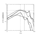
同図において、破線は、図3(b)に示す従来型の構造を採用した場合の結果を示し、実線が図7(a)に対応する結果、一点鎖線が図7(b)に対応する結果、二点鎖線が図7(c)に対応する結果を示している。何れの例の場合も、70〜250Hz(特に100〜200Hz)のスペクトルが従来型のものより低下していることが判る。
In the example shown in FIGS. 7A and 7B, the example in which the
FIG. 7C shows such a reference example. In the first reference example, a
Accordingly, the separation vortex e formed in the
FIG. 8 shows the spectral distribution of fluid vibration over time when these configurations are adopted, as in FIG.
In the figure, the broken line indicates the result when the conventional structure shown in FIG. 3B is adopted, the solid line corresponds to FIG. 7A, and the alternate long and short dash line corresponds to FIG. 7B. As a result, the alternate long and two short dashes line shows the result corresponding to FIG. In any case, it can be seen that the spectrum of 70 to 250 Hz (particularly 100 to 200 Hz) is lower than that of the conventional type.
本願において問題となる経時的流体振動が、拡散路11から接続路12に到る屈曲部14に形成される剥離渦eに起因するものであるとの観点からは、上記構造に代えて、この剥離渦eの形成自体を阻止する構成を採用してもよい。
即ち、拡散路11から接続路12に連なる屈曲部14に、屈曲部14において燃焼用空気流の剥離を防止する剥離防止手段を備えておけばよい。
In view of the fact that the fluid vibration with time, which is a problem in the present application, is caused by the separation vortex e formed in the
That is, it is only necessary to provide an anti-separation means for preventing exfoliation of the combustion air flow at the
〔第2の参考例〕
この種の剥離防止手段として、図9に示すように、拡散路11と接続路12とを接続するに、内径側の接続壁11a,12bを第2方向D2から第1方向D1へ滑らかに方向が変化する湾曲接続壁16とし滑らかに接続する。このような湾曲接続壁16を形成することで、拡散路11から接続路12に至る流れは滑らかな流れとすることとでき、経時的流体振動の発生を抑えることが可能となり、燃焼音との共鳴により発生する騒音を抑えることができる。
[Second Reference Example ]
As this type of peeling prevention means, as shown in FIG. 9, in order to connect the
〔第3・第4の参考例〕
さらに別の剥離防止手段として、図10(a)、図10(b)に示すように、拡散路11から接続路12に連なる屈曲部14に整流部17を設ける。図10(a)に示す例は剥離防止手段としての整流部17aを屈曲部14に渡って設けた例であり、図10(b)に示す例は、剥離防止手段としての整流部17bを屈曲部14より下流側となる接続路12に設けた例である。
これら例においては、整流部17には整流方向に沿って多数の流路を形成するハニカム状の整流部材を配設している。このような整流部材を整流部17に配設することで剥離渦eの形成を抑え、燃焼音との共鳴を伴った騒音の増大を抑制することができる。
〔第2の実施の形態〕
先に説明した第3、第4の参考例にあっては、拡散路11から接続路12に連なる屈曲部14に整流部17を設けるが、基本的に拡散路11の奥行き方向(接続路12の奥行き方向でもある第3方向:この例は第1、第2方向に対して第3方向が共に直交する)に関して、特別な構造を提案していない。しかしながら、図11(a)(b)に示すように、拡散路11自体若しくは、拡散路11と接続路12とに、上記奥行き方向で流路を仕切る複数の仕切り11sを設けても良い。この仕切り11sは、拡散路11の接続路側部位自体若しくは、連なる状態で拡散路11の接続路側部位と接続路12の拡散路側部位とにおいて、その奥行き方向で流路を仕切ることとなるが、このように拡散路11、若しくは拡散路11とそれに接続される接続路12とに関して、流路内の流れを分割することで、先に説明した屈曲部14を通過する流れは、弱い剥離渦しか形成できず剥離流が弱化する。結果、このような仕切りを設けることで、騒音の発生を防止できる。従って、ある種の剥離防止手段としての働きもする。
[Third and fourth reference examples ]
Further, as another peeling preventing means, as shown in FIGS. 10A and 10B, a rectifying
In these examples, the
Second Embodiment
In the third and fourth reference examples described above, the rectifying
この例の構成で、拡散路11自体に3枚の仕切り11sを設けた例を図11(a)に、拡散路11とそれに接続される接続路12とに3枚の仕切り11sを設けた例を図11(b)に示した。さらに、図12に、実線で図11(a)で示した例の経時的流体振動のスペクトル分布も示した。当該図面において、破線は従来型のものの結果を示している。この例の場合は、経時的流体振動のピーク位置が高い周波数側に逃げており、70〜250Hz(特に100〜200Hz)のスペクトルが従来型のピーク強度より低下していることが判る。
In the configuration of this example, an example in which three
さて、この種の仕切り11sの形状としては、装置の奥行き方向(本願における第3方向に相等し、図11において左右方向となる)に一様な剥離渦eが形成されるのを避ける目的のため、渦が奥行き方向の流速成分を有するように構成するのが好ましい。そのような例を示したのが図13であり、拡散路11のみに仕切り11sを設けている。
図13(a)で示す例は、各仕切り11sが奥行き方向に厚みを有した直方体形状に形成されており、仕切り11sにより分割された分割流路から流出した位置で分割された各流れが奥行き方向に広がり混合が起こり、強い剥離渦eが弱化する例である。
図13(b)で示す例は、各仕切り11sが、流れ方向下流側に向かうに従って奥行き方向に広がる断面三角形状の三角柱状に形成されており、仕切り11sにより分割された分割流路から流出した位置で分割された各流れが奥行き方向に広がり混合が起こり、強い剥離渦eが弱化する例である。
図13(c)で示す例は、各仕切り11sが、流れ方向下流側に向かうに従って奥行き方向に窄まる断面三角形状で、さらに下端側が窄まった形状に形成されており、仕切り11sにより分割された分割流路から流出した位置で分割された各流れの混合が起こり、強い剥離渦eが弱化する例である。
The shape of this type of
In the example shown in FIG. 13A, each
In the example shown in FIG. 13B, each
In the example shown in FIG. 13 (c), each
〔別実施の形態〕
(1) 上記の実施の形態においては、ファンが第1方向(上向き)に燃焼用酸素含有ガスを吹出す構成に関して説明したが、第2方向(水平方向)もしくは、第1方向とは逆方向(下向き)に吹出し、拡散路に導入される構成を採用してもよい。
さらに、ファンが第1方向(上向き)に燃焼用酸素含有ガスを吹出す構成で、前記拡散路が第2方向(水平方向)に燃焼用酸素含有ガスを方向づける構成を有する場合、両方向間で屈曲流れが形成される。この場合、拡散路への侵入部位が経時的流体振動の形成部位となる場合もあり、この屈曲部で発生する流体振動の周波数を、先に説明した70〜250Hzの範囲外とすることも好ましい態様であり、この部位に本願にいう剥離防止手段を設けることも好ましい態様である。
(2) 上記の実施の形態においては、第1方向及び第2方向が直交する場合に関して説明したが、第1方向と第2方向とが、60〜120度の範囲内で屈曲されている場合に、本願の特徴構成を採用することが有効である。
また、上記の実施の形態においては、第3方向が、第1方向及び第2方向に直交する例を示したが、第3方向と第1方向及び第2方向との交差も同様に、60〜120度の範囲内の角度で交差されている場合に本願の仕切りが有効である。
(3) 上記の実施の形態においては、燃焼装置が濃淡燃焼バーナを備えた場合を示したが、特定の混合比で燃焼を行う燃焼装置に本願に係る特徴構成を採用できる。
(4) 本願に係る燃焼装置は、実施の形態に示した給湯設備に採用できる外、蒸気発生装置、吸収式冷凍機の吸収液再生装置にも採用できる。
[Another embodiment]
(1) In the above embodiment, the configuration in which the fan blows out the oxygen-containing gas for combustion in the first direction (upward) has been described. However, the second direction (horizontal direction) or the direction opposite to the first direction is described. You may employ | adopt the structure which blows out (downward) and is introduce | transduced into a diffusion path.
Further, when the fan blows out the oxygen-containing gas for combustion in the first direction (upward), and the diffusion path has a structure for directing the oxygen-containing gas for combustion in the second direction (horizontal direction), it is bent between both directions. A flow is formed. In this case, the site of penetration into the diffusion path may be a site where fluid vibration is generated over time, and it is also preferable that the frequency of fluid vibration generated at the bent portion is outside the range of 70 to 250 Hz described above. It is an aspect, and it is also a preferable aspect to provide the peeling prevention means referred to in the present application at this portion.
(2) In the above embodiment, the case where the first direction and the second direction are orthogonal to each other has been described, but the first direction and the second direction are bent within a range of 60 to 120 degrees. In addition, it is effective to adopt the characteristic configuration of the present application.
In the above embodiment, the example in which the third direction is orthogonal to the first direction and the second direction has been described. However, the intersection of the third direction, the first direction, and the second direction is similarly 60. The partition of the present application is effective when intersecting at an angle in the range of ˜120 degrees.
(3) In the above-described embodiment, the case where the combustion device includes the light and dark combustion burner has been shown. However, the characteristic configuration according to the present application can be adopted for the combustion device that performs combustion at a specific mixing ratio.
(4) The combustion apparatus according to the present application can be employed not only in the hot water supply equipment described in the embodiment, but also in a steam generator and an absorbent regenerator of an absorption chiller.
1 燃焼装置
2 シロッコファン
3 バーナ
4 燃焼器
5 ダクト
9 ガスノズル
10 導入口
11 拡散路
12 接続路
13 ダクトケーシング
14 屈曲部
15 整流部
16 湾曲接続壁
17 整流部
26 吹出し口
A 再付着点
e 剥離渦(剥離流)
DESCRIPTION OF
Claims (7)
前記ファンの吹出し口に接続され、前記ファンにより吹出された前記酸素含有ガス流を第2方向に導き拡散させる前記拡散路と、前記拡散路の第2方向端において前記拡散路を経て供給される酸素含有ガス流を屈曲部を経て第1方向に導く接続路と、前記接続路から前記酸素含有ガス流を導入口を経て前記第2方向とは逆方向に導き、前記炭化水素系燃料と混合して燃焼させるバーナとを備え、
前記拡散路から前記接続路に連なる前記屈曲部において形成される剥離流の再付着点より下流側に前記導入口を設けるとともに、前記導入口から離間する方向に延出する延出壁を、前記拡散路の接続路側部位に設け、前記延出壁の先端において前記剥離流が形成され、
前記ファンから前記バーナに到る前記酸素含有ガス流に関し、流れが屈曲する部位において発生する経時的流体振動のピーク周波数が、混合ガスの燃焼により発生する燃焼音の周波数範囲外に設定されている燃焼装置。 A fan that blows out oxygen-containing gas for combustion, a diffusion path that is connected to a blow-out port of the fan and diffuses an oxygen-containing gas stream blown out by the fan, and an oxygen-containing gas and a hydrocarbon system that are fed from the diffusion path A combustion apparatus comprising a burner for mixing and burning fuel,
The diffusion path connected to the blower outlet of the fan and guiding and diffusing the oxygen-containing gas flow blown out by the fan in the second direction, and supplied through the diffusion path at the second direction end of the diffusion path A connection path for guiding the oxygen-containing gas flow in the first direction through the bent portion, and the oxygen-containing gas flow from the connection path through the introduction port in a direction opposite to the second direction, and mixing with the hydrocarbon-based fuel And burner to burn,
The introduction port is provided on the downstream side from the reattachment point of the separation flow formed in the bent portion connected to the connection path from the diffusion path, and an extension wall extending in a direction away from the introduction port, Provided in the connection path side part of the diffusion path, the separation flow is formed at the tip of the extension wall,
Relates to the aforementioned oxygen-containing gas stream leading to the burner from the fan, the peak frequency of the time the fluid vibration generated at the site where the flow is bent is set outside the frequency range of the combustion noise generated by the combustion of the mixed gas Combustion device.
前記ファンの吹出し口に接続され、前記ファンにより吹出された酸素含有ガス流を第2方向に導き拡散させる前記拡散路と、前記拡散路の第2方向端において前記拡散路を経て供給される酸素含有ガス流を屈曲部を経て第1方向に導く接続路と、前記接続路から前記酸素含有ガス流を導入口を経て前記第2方向とは逆方向に導き、前記炭化水素系燃料と混合して燃焼させるバーナとを備え、
前記拡散路の接続路側部位、もしくは前記拡散路の接続路側部位と少なくとも前記接続路の入口から前記導入口に到るまでの接続路部位とに、前記第1方向及び第2方向の両方向と交差する第3方向に流路を分割する仕切りを設け、
前記ファンから前記バーナに到る前記酸素含有ガス流に関し、流れが屈曲する部位において発生する経時的流体振動のピーク周波数が、混合ガスの燃焼により発生する燃焼音の周波数範囲外に設定されている燃焼装置。 A fan that blows out oxygen-containing gas for combustion, a diffusion path that is connected to a blow-out port of the fan and diffuses an oxygen-containing gas stream blown out by the fan, and an oxygen-containing gas and a hydrocarbon system that are fed from the diffusion path A combustion apparatus comprising a burner for mixing and burning fuel,
The diffusion path connected to the blowout port of the fan and guiding and diffusing the oxygen-containing gas flow blown out by the fan in the second direction, and oxygen supplied through the diffusion path at the second direction end of the diffusion path A connecting path for guiding the contained gas flow in the first direction through the bent portion, and the oxygen-containing gas stream from the connecting path through the introduction port in a direction opposite to the second direction and mixed with the hydrocarbon-based fuel. And burner to burn
Crossing both the first direction and the second direction at the connection path side part of the diffusion path, or at the connection path side part of the diffusion path and at least the connection path part from the connection path entrance to the introduction port Providing a partition for dividing the flow path in the third direction,
Relates to the aforementioned oxygen-containing gas stream leading to the burner from the fan, the peak frequency of the time the fluid vibration generated at the site where the flow is bent is set outside the frequency range of the combustion noise generated by the combustion of the mixed gas Combustion device.
前記拡散路から前記接続路に連なる前記屈曲部において形成される剥離流の再付着点より下流側に前記導入口を設けるとともに、前記導入口から離間する方向に延出する延出壁を、前記拡散路の接続路側部位に設け、前記延出壁の先端において前記剥離流が形成される燃焼装置。 A fan that blows out oxygen-containing gas for combustion, a diffusion path that is connected to the blow-out port of the fan and that guides and diffuses the oxygen-containing gas flow blown out by the fan in a second direction, and a second direction end of the diffusion path A connection path for guiding the oxygen-containing gas flow supplied through the diffusion path in a first direction through a bent portion, and a direction opposite to the second direction from the connection path through the inlet through the oxygen-containing gas flow A combustion apparatus comprising a burner for directing and mixing and burning with a hydrocarbon-based fuel,
Wherein said inlet port downstream of the reattachment of the separated flow formed in the bent portion continuous to the connecting passage from the diffusion path provided Rutotomoni, the extension wall extending in a direction away from the inlet, A combustion apparatus that is provided at a connection path side portion of the diffusion path and in which the separation flow is formed at a tip of the extension wall .
前記拡散路から前記接続路に連なる屈曲部において形成される剥離流の再付着点より下流側に前記導入口を設け、
前記拡散路の接続路側部位、もしくは前記拡散路の接続路側部位と少なくとも前記接続路の入口から前記導入口に到るまでの接続路部位とに、前記第1方向及び第2方向の両方向と交差する第3方向に流路を分割する仕切りを設けた燃焼装置。 A fan that blows out oxygen-containing gas for combustion, a diffusion path that is connected to the blow-out port of the fan and that guides and diffuses the oxygen-containing gas flow blown out by the fan in a second direction, and a second direction end of the diffusion path A connection path for guiding the oxygen-containing gas flow supplied through the diffusion path in a first direction through a bent portion, and a direction opposite to the second direction from the connection path through the inlet through the oxygen-containing gas flow A combustion apparatus comprising a burner for directing and mixing and burning with a hydrocarbon-based fuel,
The introduction port is provided on the downstream side from the reattachment point of the separation flow formed in the bent portion connected to the connection path from the diffusion path ,
Crossing both the first direction and the second direction at the connection path side part of the diffusion path, or at the connection path side part of the diffusion path and at least the connection path part from the connection path entrance to the introduction port The combustion apparatus which provided the partition which divides | segments a flow path in the 3rd direction .
Priority Applications (1)
| Application Number | Priority Date | Filing Date | Title |
|---|---|---|---|
| JP2007165248A JP5117771B2 (en) | 2006-06-23 | 2007-06-22 | Combustion device |
Applications Claiming Priority (3)
| Application Number | Priority Date | Filing Date | Title |
|---|---|---|---|
| JP2006173873 | 2006-06-23 | ||
| JP2006173873 | 2006-06-23 | ||
| JP2007165248A JP5117771B2 (en) | 2006-06-23 | 2007-06-22 | Combustion device |
Related Child Applications (1)
| Application Number | Title | Priority Date | Filing Date |
|---|---|---|---|
| JP2012153924A Division JP5433054B2 (en) | 2006-06-23 | 2012-07-09 | Combustion device |
Publications (2)
| Publication Number | Publication Date |
|---|---|
| JP2008025985A JP2008025985A (en) | 2008-02-07 |
| JP5117771B2 true JP5117771B2 (en) | 2013-01-16 |
Family
ID=39116782
Family Applications (1)
| Application Number | Title | Priority Date | Filing Date |
|---|---|---|---|
| JP2007165248A Expired - Fee Related JP5117771B2 (en) | 2006-06-23 | 2007-06-22 | Combustion device |
Country Status (1)
| Country | Link |
|---|---|
| JP (1) | JP5117771B2 (en) |
Families Citing this family (2)
| Publication number | Priority date | Publication date | Assignee | Title |
|---|---|---|---|---|
| CN101571315B (en) | 2009-06-16 | 2012-05-16 | 艾欧史密斯(中国)热水器有限公司 | Volumetric gas water heater |
| CN113606578B (en) * | 2021-08-06 | 2025-08-19 | 江苏叶茂厨卫科技有限公司 | Premixing thick-thin burner behind fan |
Family Cites Families (10)
| Publication number | Priority date | Publication date | Assignee | Title |
|---|---|---|---|---|
| JPS6391423A (en) * | 1986-10-03 | 1988-04-22 | Rinnai Corp | Forced blowing type combustion system |
| JPH01217111A (en) * | 1988-02-25 | 1989-08-30 | Rinnai Corp | Burner |
| JP2805763B2 (en) * | 1988-09-01 | 1998-09-30 | 松下電器産業株式会社 | Gas water heater |
| JPH02169915A (en) * | 1988-12-22 | 1990-06-29 | Matsushita Electric Ind Co Ltd | Forced air water heater |
| JPH09126424A (en) * | 1995-10-30 | 1997-05-16 | Osaka Gas Co Ltd | Burner |
| JP3679991B2 (en) * | 2000-11-22 | 2005-08-03 | 三菱重工業株式会社 | Silencer |
| JP2003021323A (en) * | 2001-07-03 | 2003-01-24 | Noritz Corp | Burner |
| JP2003042402A (en) * | 2001-07-30 | 2003-02-13 | Samson Co Ltd | Boiler provided with sound insulation wall in air- introducing path |
| JP2005076931A (en) * | 2003-08-29 | 2005-03-24 | Osaka Gas Co Ltd | Duct structure |
| JP4251049B2 (en) * | 2003-09-25 | 2009-04-08 | ダイキン工業株式会社 | Humidification passage connection joint |
-
2007
- 2007-06-22 JP JP2007165248A patent/JP5117771B2/en not_active Expired - Fee Related
Also Published As
| Publication number | Publication date |
|---|---|
| JP2008025985A (en) | 2008-02-07 |
Similar Documents
| Publication | Publication Date | Title |
|---|---|---|
| JP3527280B2 (en) | Combustion chamber | |
| JP5117771B2 (en) | Combustion device | |
| US20080149093A1 (en) | Heating cooking appliance and burner system thereof | |
| JP2000266385A (en) | Ventilation equipment | |
| JP5433054B2 (en) | Combustion device | |
| JP2005076931A (en) | Duct structure | |
| JP5775507B2 (en) | Combustion device | |
| US20050227195A1 (en) | Combustion burner assembly having low oxides of nitrogen emission | |
| JP2016048149A (en) | Combustion apparatus | |
| JP2013072565A (en) | Heat source machine and refrigerating cycle device | |
| JP6336379B2 (en) | Combustion device | |
| JP7569211B2 (en) | Premixed gas burner | |
| JP2014169806A (en) | Flat burner | |
| JP2014163595A (en) | Flat burner | |
| TWI660647B (en) | Heating conditioner | |
| JP2009139067A (en) | Exhaust system | |
| JP3561905B2 (en) | Combustion equipment | |
| JP3508632B2 (en) | Tornado-type intake / blower | |
| JP3789425B2 (en) | Hot air heater | |
| JP2003021323A (en) | Burner | |
| JP2018162755A (en) | Blower | |
| CN105588231A (en) | Air conditioner outdoor unit air outlet structure | |
| JP2015102046A (en) | Combustion device | |
| JP2003021319A (en) | Burner | |
| JP2008224164A (en) | Combustion apparatus |
Legal Events
| Date | Code | Title | Description |
|---|---|---|---|
| A621 | Written request for application examination |
Free format text: JAPANESE INTERMEDIATE CODE: A621 Effective date: 20100114 |
|
| A131 | Notification of reasons for refusal |
Free format text: JAPANESE INTERMEDIATE CODE: A131 Effective date: 20120510 |
|
| A521 | Request for written amendment filed |
Free format text: JAPANESE INTERMEDIATE CODE: A523 Effective date: 20120709 |
|
| TRDD | Decision of grant or rejection written | ||
| A01 | Written decision to grant a patent or to grant a registration (utility model) |
Free format text: JAPANESE INTERMEDIATE CODE: A01 Effective date: 20120920 |
|
| A01 | Written decision to grant a patent or to grant a registration (utility model) |
Free format text: JAPANESE INTERMEDIATE CODE: A01 |
|
| A61 | First payment of annual fees (during grant procedure) |
Free format text: JAPANESE INTERMEDIATE CODE: A61 Effective date: 20121018 |
|
| R150 | Certificate of patent or registration of utility model |
Free format text: JAPANESE INTERMEDIATE CODE: R150 Ref document number: 5117771 Country of ref document: JP Free format text: JAPANESE INTERMEDIATE CODE: R150 |
|
| FPAY | Renewal fee payment (event date is renewal date of database) |
Free format text: PAYMENT UNTIL: 20151026 Year of fee payment: 3 |
|
| R250 | Receipt of annual fees |
Free format text: JAPANESE INTERMEDIATE CODE: R250 |
|
| R250 | Receipt of annual fees |
Free format text: JAPANESE INTERMEDIATE CODE: R250 |
|
| R250 | Receipt of annual fees |
Free format text: JAPANESE INTERMEDIATE CODE: R250 |
|
| R250 | Receipt of annual fees |
Free format text: JAPANESE INTERMEDIATE CODE: R250 |
|
| LAPS | Cancellation because of no payment of annual fees |