JP5117823B2 - Highly stable oscillator with temperature chamber - Google Patents
Highly stable oscillator with temperature chamber Download PDFInfo
- Publication number
- JP5117823B2 JP5117823B2 JP2007294048A JP2007294048A JP5117823B2 JP 5117823 B2 JP5117823 B2 JP 5117823B2 JP 2007294048 A JP2007294048 A JP 2007294048A JP 2007294048 A JP2007294048 A JP 2007294048A JP 5117823 B2 JP5117823 B2 JP 5117823B2
- Authority
- JP
- Japan
- Prior art keywords
- crystal oscillator
- oscillation frequency
- inverter
- signal
- frequency signal
- Prior art date
- Legal status (The legal status is an assumption and is not a legal conclusion. Google has not performed a legal analysis and makes no representation as to the accuracy of the status listed.)
- Expired - Fee Related
Links
Images


Landscapes
- Oscillators With Electromechanical Resonators (AREA)
Description
本発明は、SC−CUT水晶振動子を用いた恒温槽付高安定発振器に係り、特に、起動時の安定度を向上させ、ハードウエア規模の増大を防止できる恒温槽付高安定発振器に関する。 The present invention relates to a high-stability oscillator with a thermostat using an SC-CUT crystal resonator, and more particularly to a high-stability oscillator with a thermostat capable of improving the stability at startup and preventing an increase in hardware scale.
SC−CUT水晶振動子の周波数温度特性は、上に凸状を示すものである。
従って、SC−CUT水晶振動子を用いた恒温槽付水晶発振器は、振動子の凸状の頂点で温度が安定となるように温度制御を行うものである。
The frequency-temperature characteristic of the SC-CUT crystal resonator is convex upward.
Therefore, the thermostatic chamber-equipped crystal oscillator using the SC-CUT crystal resonator performs temperature control so that the temperature becomes stable at the convex apex of the resonator.
しかしながら、恒温槽付水晶発振器の起動時は、頂点の周波数に比べて−100〜−150ppmとなり、周波数偏差が大きくなってしまう。 However, at the time of activation of the crystal oscillator with a thermostatic bath, it becomes −100 to −150 ppm as compared with the peak frequency, and the frequency deviation becomes large.
そこで、起動時の安定度向上のために、恒温槽付水晶発振器に固定発振器を付加した場合は、起動後にタイマ手段によって切替時間を決定し、更に、切替時の位相飛びをなくすために、切替の位相検出手段が必要である。 Therefore, when a fixed oscillator is added to the crystal oscillator with a thermostatic bath to improve the stability at startup, the switching time is determined by the timer means after startup, and furthermore, switching is performed to eliminate phase jumps at switching. Phase detection means is required.
尚、関連する先行技術として、特開昭59−194519号公報(特許文献1)、特開2004−64445号公報(特許文献2)がある。 As related prior arts, there are JP-A-59-194519 (Patent Document 1) and JP-A-2004-64445 (Patent Document 2).
特許文献1には、温度補償水晶発振器(TCXO:Temperature Compensated Crystal Oscillator)と恒温槽付水晶発振器(OCXO:Oven Controlled Crystal Oscillator)とを並設し、起動時はTCXOの発振周波数を採用し、OCXOが安定したらOCXOに切り替える基準周波数発生方式が示されている。 In Patent Document 1, a temperature compensated crystal oscillator (TCXO) and a crystal oscillator with a thermostatic bath (OCXO: Oven Controlled Crystal Oscillator) are juxtaposed, and the TCXO oscillation frequency is adopted at startup. A reference frequency generation method for switching to OCXO when is stabilized is shown.
また、特許文献2には、TCXOとOCXOを備え、両者の発振周波数を位相比較回路で比較して位相差の平均が周波数安定度の範囲内になれば、OCXOのウォームアップが完了して、OCXOの出力周波数をバッファで増幅して出力可能となる恒温槽付水晶発振器のウォームアップ制御方法が示されている。
しかしながら、上記従来の恒温槽付水晶発振器に固定発振器を付加した回路では、起動後に切替時間を決定するためのタイマ手段を設けたり、また、切替時の位相飛びをなくすために切替の位相検出手段が必要となり、起動時に安定度を向上させつつ、ハードウエア規模を抑えることができないという問題点があった。 However, in a circuit in which a fixed oscillator is added to the conventional crystal oscillator with a thermostat, a timer means for determining a switching time after activation is provided, or a switching phase detection means for eliminating a phase jump at the time of switching There is a problem that the hardware scale cannot be suppressed while improving the stability at the time of starting.
本発明は上記実情に鑑みて為されたもので、起動時に安定度を向上させつつ、ハードウエア規模を抑えることができる恒温槽付高安定発振器を提供することを目的とする。 The present invention has been made in view of the above circumstances, and an object of the present invention is to provide a highly stable oscillator with a thermostat that can suppress the hardware scale while improving the stability at the time of startup.
上記従来例の問題点を解決するための本発明は、恒温槽付水晶発振器と、恒温槽付水晶発振器からの発振周波数信号を入力し、水晶発振器と第1のインバータとを並列に接続して構成されるインバータ式水晶発振器と、恒温槽付水晶発振器からの発振周波数信号とインバータ式水晶発振器からの発振周波数信号を入力し、いずれかの発振周波数信号を選択するセレクタと、恒温槽付水晶発振器の発振周波数信号がインバータ式水晶発振器の発振周波数信号に同期するまでの間、前記インバータ式水晶発振器からの発振周波数信号を選択するよう前記セレクタに選択信号を出力し、恒温槽付水晶発振器の発振周波数信号がインバータ式水晶発振器の発振周波数信号に同期するようになると、恒温槽付水晶発振器からの発振周波数信号を選択するようセレクタに選択信号を出力する安定化手段とを有することを特徴とする恒温槽付高安定発振器。 The present invention for solving the problems of the above-mentioned conventional example inputs a crystal oscillator with a thermostat and an oscillation frequency signal from the crystal oscillator with a thermostat, and connects the crystal oscillator and the first inverter in parallel. The inverter type crystal oscillator, the oscillation frequency signal from the oven-controlled crystal oscillator and the oscillation frequency signal from the inverter-type crystal oscillator are input, and a selector for selecting one of the oscillation frequency signals, and the oven-controlled crystal oscillator Until the oscillation frequency signal is synchronized with the oscillation frequency signal of the inverter type crystal oscillator, the selection signal is output to the selector so as to select the oscillation frequency signal from the inverter type crystal oscillator, and the oscillation of the crystal oscillator with a thermostatic bath When the frequency signal is synchronized with the oscillation frequency signal of the inverter-type crystal oscillator, select the oscillation frequency signal from the oven-controlled crystal oscillator High stability oscillator with a thermostat and having a stabilizing means for outputting a selection signal to cormorants selector.
本発明は、上記恒温槽付高安定発振器において、恒温槽付水晶発振器とインバータ式水晶発振器との間に、コンデンサと抵抗器を直列に接続したことを特徴とする。 The present invention is characterized in that, in the high-stability oscillator with a thermostat, a capacitor and a resistor are connected in series between the crystal oscillator with a thermostat and an inverter crystal oscillator.
本発明は、上記恒温槽付高安定発振器において、安定化手段が、恒温槽付水晶発振器からの発振周波数信号とインバータ式水晶発振器からの発振周波数信号を入力し、論理積を出力するアンドゲートと、アンドゲートからの出力を積分する積分器と、積分器からの出力信号と、恒温槽付水晶発振器の発振周波数信号がインバータ式水晶発振器の発振周波数信号に同期すると認められる場合の基準値と比較し、出力信号が基準値より高くて同期していない場合はインバータ式水晶発振器からの発振周波数信号を選択する選択信号を出力し、出力信号が基準値より低くて同期している場合は恒温槽付水晶発振器からの発振周波数信号を選択する選択信号を出力する比較器とを有することを特徴とする。 According to the present invention, in the high-stability oscillator with a thermostat, the stabilizing means inputs an oscillation frequency signal from the thermostat-equipped crystal oscillator and an oscillation frequency signal from the inverter-type crystal oscillator, and outputs an AND. Integrating the output from the AND gate, the output signal from the integrator, and the reference value when the oscillation frequency signal of the oven-controlled crystal oscillator is recognized to be synchronized with the oscillation frequency signal of the inverter-type crystal oscillator When the output signal is higher than the reference value and not synchronized, a selection signal for selecting the oscillation frequency signal from the inverter type crystal oscillator is output, and when the output signal is lower than the reference value and synchronized, the thermostatic chamber And a comparator for outputting a selection signal for selecting an oscillation frequency signal from the attached crystal oscillator.
本発明は、上記恒温槽付高安定発振器において、恒温槽付水晶発振器の発振周波数信号がインバータ式水晶発振器の発振周波数信号に同期して、恒温槽付水晶発振器からの発振周波数信号が選択された後に、インバータ式水晶発振器からの発振周波数信号を選択しないように制御する安定化維持手段を設けたことを特徴とする。 According to the present invention, in the high-stability oscillator with a thermostat, the oscillation frequency signal of the crystal oscillator with a thermostat is selected in synchronization with the oscillation frequency signal of the inverter crystal oscillator. Later, a stabilization maintaining means for controlling so as not to select an oscillation frequency signal from the inverter type crystal oscillator is provided.
本発明は、上記恒温槽付高安定発振器において、安定化維持手段が、比較器からの入力信号を反転出力する第2のインバータと、第2のインバータのからの入力をクロック端子に入力し、入力端子に電源が入力され、反転出力端子からの信号を第1のインバータに電源として供給し、反転出力端子からの信号がセレクタへの選択信号として出力するフリップフロップとを有することを特徴とする。
According to the present invention, in the high-stability oscillator with a thermostatic bath, the stabilization maintaining means inputs a second inverter that inverts and outputs an input signal from the comparator, and an input from the second inverter to a clock terminal, And a flip-flop for supplying power to the input terminal , supplying a signal from the inverting output terminal to the first inverter as power, and outputting the signal from the inverting output terminal as a selection signal to the selector. .
本発明によれば、安定化手段が、恒温槽付水晶発振器の発振周波数信号がインバータ式水晶発振器の発振周波数信号に同期するまでの間、インバータ式水晶発振器からの発振周波数信号を選択するようセレクタに選択信号を出力し、恒温槽付水晶発振器の発振周波数信号がインバータ式水晶発振器の発振周波数信号に同期するようになると、恒温槽付水晶発振器からの発振周波数信号を選択するようセレクタに選択信号を出力する恒温槽付高安定発振器としているので、起動時に安定度を向上させつつ、ハードウエア規模を抑えることができる効果がある。 According to the present invention, the stabilizing means selects the oscillation frequency signal from the inverter-type crystal oscillator until the oscillation frequency signal of the oven-controlled crystal oscillator is synchronized with the oscillation frequency signal of the inverter-type crystal oscillator. When the oscillation frequency signal of the oven-controlled crystal oscillator is synchronized with the oscillation frequency signal of the inverter-type crystal oscillator, the selector selects the oscillation frequency signal from the oven-controlled crystal oscillator. Therefore, there is an effect that the hardware scale can be suppressed while improving the stability at the time of startup.
本発明によれば、恒温槽付水晶発振器とインバータ式水晶発振器との間に、コンデンサと抵抗器を直列に接続した上記恒温槽付高安定発振器としているので、コンデンサと抵抗器の定数によって、インバータ式水晶発振器に対する干渉度を調整できる効果がある。 According to the present invention, since the above-mentioned high-stability oscillator with a thermostat is provided with a capacitor and a resistor connected in series between a crystal oscillator with a thermostat and an inverter-type crystal oscillator, the inverter is controlled according to the constants of the capacitor and the resistor. There is an effect that the degree of interference with the crystal oscillator can be adjusted.
本発明によれば、安定化維持手段が、恒温槽付水晶発振器の発振周波数信号がインバータ式水晶発振器の発振周波数信号に同期して、恒温槽付水晶発振器からの発振周波数信号が選択された後に、インバータ式水晶発振器からの発振周波数信号を選択しないように制御する上記恒温槽付高安定発振器としているので、恒温槽付水晶発振器が安定化した後は、インバータ式水晶発振器の発振周波数信号を選択する状態に戻ってしまうのを防止できる効果がある。 According to the present invention, the stabilization maintaining means is configured so that the oscillation frequency signal of the thermostatic oven crystal oscillator is synchronized with the oscillation frequency signal of the inverter crystal oscillator and the oscillation frequency signal from the thermostatic oven crystal oscillator is selected. Because the high-stability oscillator with a thermostatic chamber is controlled so as not to select the oscillation frequency signal from the inverter-type crystal oscillator, the oscillation frequency signal of the inverter-type crystal oscillator is selected after the temperature-controlled crystal oscillator is stabilized There is an effect of preventing the return to the state to be performed.
本発明の実施の形態について図面を参照しながら説明する。
[実施の形態の概要]
本発明の実施の形態に係る恒温槽付高安定発振器は、OCXOと、OCXOからの発振周波数信号を入力し、水晶発振器と第1のインバータとを並列に接続して構成されるインバータ式水晶発振器と、OCXOからの発振周波数信号とインバータ式水晶発振器からの発振周波数信号を入力し、いずれかを選択するセレクタと、OCXOの発振周波数信号がインバータ式水晶発振器の発振周波数信号に同期するまでの間、インバータ式水晶発振器からの発振周波数信号を選択するようセレクタに選択信号を出力し、OCXOの発振周波数信号がインバータ式水晶発振器の発振周波数信号に同期するようになると、OCXOからの発振周波数信号を選択するようセレクタに選択信号を出力する安定化手段とを有するものであり、起動時に安定度を向上させつつ、ハードウエア規模を抑えることができるものである。
Embodiments of the present invention will be described with reference to the drawings.
[Outline of the embodiment]
A high-stability oscillator with a thermostat according to an embodiment of the present invention is an inverter crystal oscillator configured by inputting OCXO and an oscillation frequency signal from OCXO and connecting the crystal oscillator and the first inverter in parallel. And an oscillation frequency signal from the OCXO and an oscillation frequency signal from the inverter type crystal oscillator, and a selector for selecting either of them, and until the oscillation frequency signal of the OCXO is synchronized with the oscillation frequency signal of the inverter type crystal oscillator When the OCXO oscillation frequency signal is synchronized with the oscillation frequency signal of the inverter crystal oscillator, the selection signal is output to the selector so as to select the oscillation frequency signal from the inverter crystal oscillator. And a stabilizing means for outputting a selection signal to the selector so that the selection can be made. While above, in which it is possible to suppress the hardware scale.
また、本発明の実施の形態に係る恒温槽付高安定発振器は、OCXOの発振周波数信号がインバータ式水晶発振器の発振周波数信号に同期して、OCXOからの発振周波数信号が選択された後に、インバータ式水晶発振器からの発振周波数信号を選択しないように制御する安定化維持手段を備えたものであり、OCXOが一度安定化した後は、インバータ式水晶発振器の発振周波数信号を選択する状態に戻ってしまうのを防止できるものである。 In addition, the high-stability oscillator with a thermostat according to the embodiment of the present invention is configured so that the oscillation frequency signal of the OCXO is synchronized with the oscillation frequency signal of the inverter-type crystal oscillator and the oscillation frequency signal from the OCXO is selected. Stabilizing means for controlling the oscillation frequency signal from the crystal oscillator so as not to be selected. After the OCXO has stabilized once, it returns to the state of selecting the oscillation frequency signal of the inverter crystal oscillator. Can be prevented.
[本発振器の構成:図1]
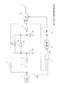
本発明の実施の形態に係る恒温槽付高安定発振器(本発振器)について図1を参照しながら説明する。図1は、本発明の実施の形態に係る恒温槽付高安定発振器の構成ブロック図である。
本発振器は、図1に示すように、恒温槽水晶発振器(OCXO)1と、第1のバッファ2と、コンデンサ3と、抵抗器4と、インバータ式水晶発振器5と、第2のバッファ6と、アンドゲート7と、積分器8と、比較器(CMP:Comparator)9と、セレクタ(SEL:Selector)10と、出力端子11とを基本的に有している。
ここで、アンドゲート7、積分器8、比較器9は、OCXO1の安定化検出手段となっている。
[Configuration of this oscillator: Fig. 1]
A highly stable oscillator with a thermostat (this oscillator) according to an embodiment of the present invention will be described with reference to FIG. FIG. 1 is a block diagram showing the configuration of a high-stability oscillator with a thermostat according to an embodiment of the present invention.
As shown in FIG. 1, the present oscillator includes an oven controlled crystal oscillator (OCXO) 1, a
Here, the AND gate 7, the
[本発振器の各部]
本発振器の各部について具体的に説明する。
恒温槽水晶発振器(OCXO)1は、水晶発振回路を恒温槽に挿入することにより、高安定化を図った発振器である。OCXO1から出力された発振周波数信号は分岐されて、第1のバッファ2、コンデンサ3、アンドゲート7の一端に入力される。
[Each oscillator part]
Each part of the oscillator will be specifically described.
The thermostatic oven crystal oscillator (OCXO) 1 is an oscillator that achieves high stability by inserting a crystal oscillation circuit into the thermostatic oven. The oscillation frequency signal output from the OCXO 1 is branched and input to one end of the
第1のバッファ2は、OCXO1からの信号を増幅してセレクタ10の一方の入力端子に出力する。
コンデンサ3及び抵抗器4は、OCXO1とインバータ式水晶発振器5との間に直列に接続され、コンデンサ3と抵抗器4の定数によって、インバータ式水晶発振器5に対する干渉度を調整する。当然、振幅が大きいほど、同期範囲は3〜5ppm程度に広がるが、ジッタ(信号エッジのゆらぎ成分)が増大するので、適宜定数を決定する。
The
The capacitor 3 and the resistor 4 are connected in series between the OCXO 1 and the inverter type crystal oscillator 5, and the degree of interference with the inverter type crystal oscillator 5 is adjusted by the constants of the capacitor 3 and the resistor 4. Naturally, the greater the amplitude, the wider the synchronization range is in the range of 3 to 5 ppm, but the jitter (the signal edge fluctuation component) increases, so a constant is determined as appropriate.
インバータ式水晶発振器5は、固定の水晶発振器5aと、入力信号の位相を反転させるインバータ5bとが並列に接続され、その両端にコンデンサ5cとコンデンサ5dの一端が接続され、これらコンデンサの他端が接地されるようにして構成される。
In the inverter type crystal oscillator 5, a
インバータ式水晶発振器5は、インバータ5bの出力を、水晶発振器5aを通してインバータ5bの入力に戻すことにより、水晶発振器5aの固有周波数で安定した動作を行わせるものである。
尚、インバータ式水晶発振器5は、インバータ5bにより出力が反転出力となる。
The inverter-type crystal oscillator 5 returns the output of the
Note that the inverter-type crystal oscillator 5 is inverted by the
第2のバッファ6は、インバータ式水晶発振器5からの出力を増幅し、分岐して一方をセレクタ10に、他方をアンドゲート7に出力する。
アンドゲート7は、第2のバッファ6からの信号とOCXO1からの信号について論理積を出力する。
積分器8は、アンドゲート7からの出力を一定時間積分して比較器9に出力する。
The
The AND gate 7 outputs a logical product of the signal from the
The
比較器(CMP)9は、積分器8での積分信号を基準値と比較し、基準値より高い(High)レベルの場合は、H(High)レベル信号を出力し、基準値より低い(Low)レベルの場合は、L(Low)レベル信号を出力する。
The comparator (CMP) 9 compares the integrated signal from the
基準値は、OCXO1とインバータ式水晶発振器5の出力について同期がとれていない場合は誤差が多くなるため積分値が高くなり、同期がとれている場合は誤差が少なくなるため積分値が低くなることから、同期がとれるようになった場合の積分値の値が設定される。 When the outputs of the OCXO 1 and the inverter-type crystal oscillator 5 are not synchronized, the reference value is increased because the error increases, and when the synchronization is established, the error is decreased and the integrated value is decreased. Thus, the value of the integral value when synchronization can be established is set.
つまり、比較器8からの出力信号がHレベルであるときは、同期がとれていない状態であり、比較器8からの出力信号がLレベルであって基準信号より低いレベルであるときは、同期がとれている状態である。
That is, when the output signal from the
セレクタ(SEL)10は、第1のバッファ2からの出力と第2のバッファ6からの出力を比較器9からの信号(選択信号)によって選択し、出力端子11に出力する。
具体的には、比較器9からのHレベル信号(同期がとれていない)の場合、インバータ式水晶発振器5からの信号を第2のバッファ6で増幅した信号が選択されて出力端子11に出力される。また、比較器9からのLレベル信号(同期がとれている)の場合、OCXO1からの信号を第1のバッファ2で増幅した信号が選択されて出力端子11に出力される。
The selector (SEL) 10 selects the output from the
Specifically, in the case of the H level signal from the comparator 9 (not synchronized), a signal obtained by amplifying the signal from the inverter type crystal oscillator 5 by the
[本発振器の動作]
次に、本発振器の動作を説明する。
本発振器は、OCXO1の起動時は、OCXO1とインバータ式水晶発振器5とが同期がとれていない場合となり、安定化検出手段である、アンドゲート7での差分が大きくなり、積分器8での積分値が高くなって、比較器9で基準値より高い場合、Hレベル信号をセレクタ10に出力する。
セレクタ10は、比較器9からのHレベル信号により、第2のバッファ6からの周波数信号(インバータ式水晶発振器5の発振周波数信号を増幅した信号)を選択して出力端子11に出力する。
[Operation of this oscillator]
Next, the operation of this oscillator will be described.
In this oscillator, when the OCXO 1 is started, the OCXO 1 and the inverter type crystal oscillator 5 are not synchronized with each other, and the difference in the AND gate 7 which is the stabilization detecting means becomes large, and the integration in the
The
そして、OCXO1とインバータ式水晶発振器5とが同期がとれるようになると、アンドゲート7での差分が小さくなり、積分器8での積分値が低くなって、比較器9で基準値より低い場合、Lレベル信号をセレクタ10に出力する。
セレクタ10は、比較器9からのLレベル信号により、第1のバッファ2からの周波数信号(OCXO1の発振周波数を増幅した信号)を選択して出力端子11に出力する。
When the OCXO 1 and the inverter type crystal oscillator 5 are synchronized, the difference in the AND gate 7 is reduced, the integration value in the
The
尚、インバータ式水晶発振器5をOCXO1内のSC−CUT水晶振動子付近に実装すれば、インバータ式水晶発振器5の温度環境が安定となって、起動時に更に安定度向上を見込むことができる。 If the inverter type crystal oscillator 5 is mounted in the vicinity of the SC-CUT crystal resonator in the OCXO 1, the temperature environment of the inverter type crystal oscillator 5 becomes stable, and further stability improvement can be expected at the time of startup.
[同期時のタイムチャート:図2]
OCXO1の発振周波数とインバータ式水晶発振器5の発振周波数が同期している場合におけるアンドゲートの出力信号の状態を図2に示す。図2は、アンドゲートにおける2つの入力信号と出力信号を示すタイムチャートである。
[Time chart during synchronization: Fig. 2]
FIG. 2 shows the state of the output signal of the AND gate when the oscillation frequency of the OCXO 1 and the oscillation frequency of the inverter type crystal oscillator 5 are synchronized. FIG. 2 is a time chart showing two input signals and output signals in the AND gate.
本発振器において同期がとれている場合には、図2に示すように、OCXO1からの入力信号101と第2のバッファ6からの出力信号(反転出力)102とは対称的に波形となっており、両信号の論理積信号103は、両信号の立ち上がり及び立ち下がりにおいて垂直方向に信号が立つように表れ、この論理積信号を積分器8で積分すると、基準値より低いレベル(Lレベル)の信号が比較器9に出力される。
When the oscillator is synchronized, as shown in FIG. 2, the input signal 101 from the OCXO 1 and the output signal (inverted output) 102 from the
そして、比較器9では、Lレベル信号が基準値より低いため、セレクタ10に対してLレベル信号を出力する。
セレクタ10は、比較器9からのLレベル信号によって第1のバッファ2からの周波数信号を選択して出力端子11に出力するようになっている。
The comparator 9 outputs the L level signal to the
The
[本発振器の効果]
本発振器によれば、OCXO1の起動時にインバータ式水晶発振器5の発振周波数に同期していない場合には、アンドゲート7、積分器8、比較器9の安定化手段がセレクタ10に対してインバータ式水晶発振器5の発振周波数を選択するよう指示し、OCXO1が安定化してインバータ式水晶発振器5の発振周波数に同期するようになった場合には、安定化手段がセレクタ10に対してOCXO1の発振周波数を選択するよう指示するようになっているので、起動時に安定度を向上させつつ、タイマ手段や切替時の位相飛びをなくすための位相検出手段を不要として、ハードウエア規模を抑えることができる効果がある。
[Effect of this oscillator]
According to this oscillator, when the OCXO 1 is not started up, the stabilization means of the AND gate 7, the
[応用例:図3]
次に、本発振器の応用例について図3を参照しながら説明する。図3は、本発振器の応用例の構成ブロック図である。
応用例の発振器は、図3に示すように、図1の本発振器に対してOCXO1の恒温槽の温度が下がっても、OCXO1の発振周波数を選択し続け、インバータ式水晶発振器5の発振周波数に切り替わってしまうのを防止する安定化維持手段を設けている。
[Application example: Fig. 3]
Next, an application example of the present oscillator will be described with reference to FIG. FIG. 3 is a configuration block diagram of an application example of the present oscillator.
As shown in FIG. 3, the oscillator of the application example continues to select the oscillation frequency of the OCXO 1 even when the temperature of the thermostatic chamber of the OCXO 1 is lowered with respect to the present oscillator of FIG. Stabilization maintaining means for preventing switching is provided.
安定化維持手段は、電源Vcc12と、当該電源12に直列に接続する抵抗13と、抵抗13に並列に接続するコンデンサ14と、フリップフロップ(F/F)15と、インバータ16とを有している。
The stabilization maintaining means includes a
電源12が直列接続の抵抗13と並列接続のコンデンサ14を介して、フリップフロップ15の入力端子D及びクリア端子CLRに入力される。
フリップフロップ15のクロック端子CKには比較器9の出力を反転するインバータ16が接続されている。
そして、フリップフロップ15の反転出力(反転Q)端子がセレクタ10、インバータ5b、第2のバッファ6に接続している。
The
An
The inverted output (inverted Q) terminal of the flip-
[応用例の動作]
フリップフロップ15は、電源12の立ち上がりに対して抵抗13とコンデンサ14の作用によって数ms遅れて立ち上がるようになっている。
本発振器で説明した通り、OCXO1の起動時は、積分器8からの出力はHレベルとなるため、比較器9はHレベル信号を出力する。よって、インバータ16は、そのHレベルの信号を反転してLレベル信号をフリップフロップ15のクロック端子CKに出力する。
[Operation of application example]
The flip-
As described in this oscillator, when the OCXO 1 is activated, the output from the
フリップフロップ15のクロック端子CKに入力される信号がLレベル信号であるため、出力(Q)端子はL(Low)レベル信号を出力して、反転Q端子はH(High)レベル信号を出力する。
Since the signal input to the clock terminal CK of the flip-
フリップフロップ15の反転Q端子からの出力(Hレベル信号)がセレクタ10、インバータ5b、第2のバッファ6に入力され、インバータ5b、第2のバッファ6は当該Hレベル信号を電源供給として動作し、セレクタ10はインバータ式水晶発振器5の発振周波数を選択するようになっている。
An output (H level signal) from the inverted Q terminal of the flip-
そして、OCXO1が安定化してインバータ式水晶発振器5の発振周波数に同期するようになると、積分器8からの出力はLレベルとなるため、比較器9はLレベル信号を出力する。よって、インバータ16は、そのLレベルの信号を反転してHレベル信号をフリップフロップ15のクロック端子CKに出力する。
When OCXO1 is stabilized and synchronized with the oscillation frequency of the inverter type crystal oscillator 5, the output from the
フリップフロップ15のクロック端子CKに入力される信号がHレベル信号であるため、出力端子はHレベル信号を出力して、反転Q端子はLレベル信号を出力する。
Since the signal input to the clock terminal CK of the flip-
フリップフロップ15の反転Q端子からの出力(Lレベル信号)がセレクタ10、インバータ5b、第2のバッファ6に入力され、インバータ5b、第2のバッファ6は当該Lレベル信号により電源供給が停止されて動作停止し、セレクタ10はOCXO1の発振周波数を選択するようになる。
The output (L level signal) from the inverted Q terminal of the flip-
その後、OCXO1の発振周波数の状態に拘わらず、インバータ5bと第2のバッファ6を停止しているので、積分器8からの出力信号はLレベルのままであり、従って、フリップフロップ15の反転Q端子からはLレベル信号が出力され続けて、セレクタ10はOCXO1の発振周波数を選択した状態を継続する。
これにより、一度、OCXO1が安定化した後は、インバータ式水晶発振器5の発振周波数を選択する状態に戻ってしまうのを防止するものである。
Thereafter, the
Thereby, once OCXO1 is stabilized, it is prevented from returning to the state in which the oscillation frequency of the inverter type crystal oscillator 5 is selected.
本発明は、起動時に安定度を向上させつつ、ハードウエア規模を抑えることができる恒温槽付高安定発振器に好適である。 INDUSTRIAL APPLICABILITY The present invention is suitable for a highly stable oscillator with a thermostatic bath that can suppress the hardware scale while improving the stability at the time of startup.
1…恒温槽水晶発振器(OCXO)、 2…第1のバッファ、 3…コンデンサ、 4…抵抗器、 5…インバータ式水晶発振器、 6…第2のバッファ、 7…アンドゲート、 8…積分器、 9…比較器(CMP)、 10…セレクタ(SEL)、 11…出力端子、 12…電源、 13…抵抗、 14…コンデンサ、 15…フリップフロップ、 16…インバータ DESCRIPTION OF SYMBOLS 1 ... Constant temperature chamber crystal oscillator (OCXO), 2 ... 1st buffer, 3 ... Capacitor, 4 ... Resistor, 5 ... Inverter type crystal oscillator, 6 ... 2nd buffer, 7 ... And gate, 8 ... Integrator, DESCRIPTION OF SYMBOLS 9 ... Comparator (CMP), 10 ... Selector (SEL), 11 ... Output terminal, 12 ... Power supply, 13 ... Resistor, 14 ... Capacitor, 15 ... Flip-flop, 16 ... Inverter
Claims (5)
前記恒温槽付水晶発振器の発振周波数信号が前記インバータ式水晶発振器の発振周波数信号に同期するまでの間、前記インバータ式水晶発振器からの発振周波数信号を選択するよう前記セレクタに選択信号を出力し、前記恒温槽付水晶発振器の発振周波数信号が前記インバータ式水晶発振器の発振周波数信号に同期するようになると、前記恒温槽付水晶発振器からの発振周波数信号を選択するよう前記セレクタに選択信号を出力する安定化手段とを有することを特徴とする恒温槽付高安定発振器。 A crystal oscillator with a thermostat, an inverter type crystal oscillator configured by inputting an oscillation frequency signal from the crystal oscillator with a thermostat and connecting the crystal oscillator and the first inverter in parallel, and the crystal with the thermostat A selector that inputs an oscillation frequency signal from an oscillator and an oscillation frequency signal from the inverter-type crystal oscillator, and selects any oscillation frequency signal;
Until the oscillation frequency signal of the crystal oscillator with a thermostat is synchronized with the oscillation frequency signal of the inverter crystal oscillator, a selection signal is output to the selector so as to select the oscillation frequency signal from the inverter crystal oscillator, When the oscillation frequency signal of the thermostat crystal oscillator is synchronized with the oscillation frequency signal of the inverter crystal oscillator, a selection signal is output to the selector so as to select the oscillation frequency signal from the thermostat crystal oscillator. A highly stable oscillator with a thermostatic bath, characterized by comprising stabilization means.
恒温槽付水晶発振器からの発振周波数信号とインバータ式水晶発振器からの発振周波数信号を入力し、論理積を出力するアンドゲートと、
前記アンドゲートからの出力を積分する積分器と、
前記積分器からの出力信号と、前記恒温槽付水晶発振器の発振周波数信号が前記インバータ式水晶発振器の発振周波数信号に同期すると認められる場合の基準値と比較し、前記出力信号が前記基準値より高くて同期していない場合は前記インバータ式水晶発振器からの発振周波数信号を選択する選択信号を出力し、前記出力信号が前記基準値より低くて同期している場合は前記恒温槽付水晶発振器からの発振周波数信号を選択する選択信号を出力する比較器とを有することを特徴とする請求項1又は2記載の恒温槽付高安定発振器。 Stabilization means
An AND gate that inputs an oscillation frequency signal from a crystal oscillator with a thermostat and an oscillation frequency signal from an inverter type crystal oscillator, and outputs a logical product;
An integrator for integrating the output from the AND gate;
The output signal from the integrator is compared with a reference value when the oscillation frequency signal of the thermostat crystal oscillator is recognized to be synchronized with the oscillation frequency signal of the inverter crystal oscillator, and the output signal is more than the reference value. When it is high and not synchronized, it outputs a selection signal for selecting an oscillation frequency signal from the inverter type crystal oscillator, and when the output signal is synchronized with being lower than the reference value, the thermostat crystal oscillator A high-stability oscillator with a thermostat according to claim 1 or 2, further comprising a comparator that outputs a selection signal for selecting the oscillation frequency signal.
比較器からの入力信号を反転出力する第2のインバータと、
前記第2のインバータのからの入力をクロック端子に入力し、入力端子に電源が入力され、反転出力端子からの信号を第1のインバータに電源として供給し、前記反転出力端子からの信号がセレクタへの選択信号として出力するフリップフロップとを有することを特徴とする請求項1乃至4のいずれか記載の恒温槽付高安定発振器。 Stabilization maintenance means
A second inverter that inverts and outputs the input signal from the comparator;
The input from the second inverter is input to the clock terminal, power is input to the input terminal, the signal from the inverting output terminal is supplied as power to the first inverter, and the signal from the inverting output terminal is the selector. A high-stable oscillator with a thermostatic bath according to any one of claims 1 to 4, further comprising a flip-flop that outputs as a selection signal to.
Priority Applications (1)
| Application Number | Priority Date | Filing Date | Title |
|---|---|---|---|
| JP2007294048A JP5117823B2 (en) | 2007-11-13 | 2007-11-13 | Highly stable oscillator with temperature chamber |
Applications Claiming Priority (1)
| Application Number | Priority Date | Filing Date | Title |
|---|---|---|---|
| JP2007294048A JP5117823B2 (en) | 2007-11-13 | 2007-11-13 | Highly stable oscillator with temperature chamber |
Publications (2)
| Publication Number | Publication Date |
|---|---|
| JP2009124291A JP2009124291A (en) | 2009-06-04 |
| JP5117823B2 true JP5117823B2 (en) | 2013-01-16 |
Family
ID=40816001
Family Applications (1)
| Application Number | Title | Priority Date | Filing Date |
|---|---|---|---|
| JP2007294048A Expired - Fee Related JP5117823B2 (en) | 2007-11-13 | 2007-11-13 | Highly stable oscillator with temperature chamber |
Country Status (1)
| Country | Link |
|---|---|
| JP (1) | JP5117823B2 (en) |
Families Citing this family (2)
| Publication number | Priority date | Publication date | Assignee | Title |
|---|---|---|---|---|
| RU2429561C1 (en) * | 2010-07-05 | 2011-09-20 | Открытое акционерное общество "МОРИОН" | Temperature-controlled quartz generator with low readiness time |
| US10234336B2 (en) * | 2015-08-06 | 2019-03-19 | Sandisk Technologies Llc | Ring oscillators for temperature detection in wideband supply noise environments |
Family Cites Families (6)
| Publication number | Priority date | Publication date | Assignee | Title |
|---|---|---|---|---|
| JPS59194519A (en) * | 1983-04-19 | 1984-11-05 | Toyo Commun Equip Co Ltd | Method for generating reference frequency |
| JPH0336211U (en) * | 1989-08-21 | 1991-04-09 | ||
| JPH0856120A (en) * | 1994-08-10 | 1996-02-27 | Yaesu Musen Co Ltd | Reference oscillator circuit |
| JP2980318B1 (en) * | 1998-11-06 | 1999-11-22 | 埼玉日本電気株式会社 | Warm-up circuit and mobile communication base station apparatus using the same |
| JP2001257531A (en) * | 2000-03-14 | 2001-09-21 | Toyo Commun Equip Co Ltd | Crystal oscillator |
| JP3871977B2 (en) * | 2002-07-29 | 2007-01-24 | 埼玉日本電気株式会社 | Warm-up control method for crystal oscillator with thermostatic bath, clock generation circuit and mobile communication base station apparatus using this method |
-
2007
- 2007-11-13 JP JP2007294048A patent/JP5117823B2/en not_active Expired - Fee Related
Also Published As
| Publication number | Publication date |
|---|---|
| JP2009124291A (en) | 2009-06-04 |
Similar Documents
| Publication | Publication Date | Title |
|---|---|---|
| JP6045961B2 (en) | Crystal oscillator and oscillation device | |
| CN101652928B (en) | Oscillation frequency control circuit | |
| JP6548411B2 (en) | Oscillator | |
| JP5117823B2 (en) | Highly stable oscillator with temperature chamber | |
| US9634677B2 (en) | Clock generator and integrated circuit using the same and injection-locked phase-locked loop control method | |
| JP2013143601A (en) | Oscillation device | |
| JP2015095099A (en) | Temperature control device and oscillation device | |
| JP6509810B2 (en) | Quartz oscillator and method of manufacturing quartz oscillator | |
| US9225342B2 (en) | Oscillation device | |
| CN104467822A (en) | Oscillator | |
| JP6172989B2 (en) | Oscillator | |
| JP6804347B2 (en) | Phase control oscillator | |
| US20150054590A1 (en) | Oven controlled crystal oscillator | |
| JP2021136642A (en) | Oscillator | |
| JP2004172686A (en) | Reference signal generator | |
| JP2001257531A (en) | Crystal oscillator | |
| JP2000323987A (en) | Pll circuit | |
| CN101997545B (en) | Frequency synthesizer | |
| JP2015198291A (en) | oscillation device | |
| JP2018148514A (en) | Phase controlled oscillator | |
| JP2015170997A (en) | Temperature compensated oscillation device and temperature compensated piezoelectric oscillator | |
| JP2021136643A (en) | Oscillator | |
| JP2005348034A (en) | Voltage-controlled oscillator | |
| JP2022037573A (en) | Digital PLL circuit | |
| JP2010278630A (en) | Digital controlled frequency generation device |
Legal Events
| Date | Code | Title | Description |
|---|---|---|---|
| A621 | Written request for application examination |
Free format text: JAPANESE INTERMEDIATE CODE: A621 Effective date: 20101028 |
|
| A521 | Written amendment |
Free format text: JAPANESE INTERMEDIATE CODE: A523 Effective date: 20110930 |
|
| A131 | Notification of reasons for refusal |
Free format text: JAPANESE INTERMEDIATE CODE: A131 Effective date: 20120619 |
|
| A521 | Written amendment |
Free format text: JAPANESE INTERMEDIATE CODE: A523 Effective date: 20120627 |
|
| TRDD | Decision of grant or rejection written | ||
| A01 | Written decision to grant a patent or to grant a registration (utility model) |
Free format text: JAPANESE INTERMEDIATE CODE: A01 Effective date: 20121016 |
|
| A01 | Written decision to grant a patent or to grant a registration (utility model) |
Free format text: JAPANESE INTERMEDIATE CODE: A01 |
|
| A61 | First payment of annual fees (during grant procedure) |
Free format text: JAPANESE INTERMEDIATE CODE: A61 Effective date: 20121018 |
|
| R150 | Certificate of patent or registration of utility model |
Free format text: JAPANESE INTERMEDIATE CODE: R150 |
|
| FPAY | Renewal fee payment (event date is renewal date of database) |
Free format text: PAYMENT UNTIL: 20151026 Year of fee payment: 3 |
|
| FPAY | Renewal fee payment (event date is renewal date of database) |
Free format text: PAYMENT UNTIL: 20151026 Year of fee payment: 3 |
|
| LAPS | Cancellation because of no payment of annual fees |