JP5118515B2 - 先端工具案内装置 - Google Patents
先端工具案内装置 Download PDFInfo
- Publication number
- JP5118515B2 JP5118515B2 JP2008060732A JP2008060732A JP5118515B2 JP 5118515 B2 JP5118515 B2 JP 5118515B2 JP 2008060732 A JP2008060732 A JP 2008060732A JP 2008060732 A JP2008060732 A JP 2008060732A JP 5118515 B2 JP5118515 B2 JP 5118515B2
- Authority
- JP
- Japan
- Prior art keywords
- tip tool
- tool guide
- water chamber
- turning
- support portion
- Prior art date
- Legal status (The legal status is an assumption and is not a legal conclusion. Google has not performed a legal analysis and makes no representation as to the accuracy of the status listed.)
- Active
Links
- 230000003014 reinforcing effect Effects 0.000 claims description 90
- 238000003825 pressing Methods 0.000 claims description 86
- XLYOFNOQVPJJNP-UHFFFAOYSA-N water Substances O XLYOFNOQVPJJNP-UHFFFAOYSA-N 0.000 claims description 81
- 238000005192 partition Methods 0.000 claims description 32
- 210000000078 claw Anatomy 0.000 claims description 17
- 238000009434 installation Methods 0.000 description 17
- 238000006243 chemical reaction Methods 0.000 description 13
- 230000007246 mechanism Effects 0.000 description 11
- 230000002093 peripheral effect Effects 0.000 description 9
- 230000002787 reinforcement Effects 0.000 description 8
- 238000005480 shot peening Methods 0.000 description 8
- 230000000694 effects Effects 0.000 description 7
- 238000005096 rolling process Methods 0.000 description 7
- 230000005484 gravity Effects 0.000 description 6
- 238000002347 injection Methods 0.000 description 6
- 239000007924 injection Substances 0.000 description 6
- 238000000034 method Methods 0.000 description 6
- 238000005520 cutting process Methods 0.000 description 5
- 238000011282 treatment Methods 0.000 description 4
- 238000006073 displacement reaction Methods 0.000 description 3
- 230000008569 process Effects 0.000 description 3
- 238000010586 diagram Methods 0.000 description 2
- 230000004308 accommodation Effects 0.000 description 1
- 238000005452 bending Methods 0.000 description 1
- 239000000470 constituent Substances 0.000 description 1
- 238000005260 corrosion Methods 0.000 description 1
- 230000007797 corrosion Effects 0.000 description 1
- 238000005336 cracking Methods 0.000 description 1
- 239000012530 fluid Substances 0.000 description 1
- 230000017525 heat dissipation Effects 0.000 description 1
- 238000007689 inspection Methods 0.000 description 1
- 238000012423 maintenance Methods 0.000 description 1
- 239000002184 metal Substances 0.000 description 1
- 238000010248 power generation Methods 0.000 description 1
- 230000009467 reduction Effects 0.000 description 1
- 230000008439 repair process Effects 0.000 description 1
- 238000003860 storage Methods 0.000 description 1
- 230000001629 suppression Effects 0.000 description 1
- 239000013585 weight reducing agent Substances 0.000 description 1
Images


Classifications
-
- F—MECHANICAL ENGINEERING; LIGHTING; HEATING; WEAPONS; BLASTING
- F22—STEAM GENERATION
- F22B—METHODS OF STEAM GENERATION; STEAM BOILERS
- F22B37/00—Component parts or details of steam boilers
- F22B37/002—Component parts or details of steam boilers specially adapted for nuclear steam generators, e.g. maintenance, repairing or inspecting equipment not otherwise provided for
- F22B37/003—Maintenance, repairing or inspecting equipment positioned in or via the headers
- F22B37/005—Positioning apparatus specially adapted therefor
Landscapes
- Physics & Mathematics (AREA)
- Engineering & Computer Science (AREA)
- High Energy & Nuclear Physics (AREA)
- Thermal Sciences (AREA)
- Mechanical Engineering (AREA)
- General Engineering & Computer Science (AREA)
- Manipulator (AREA)
- Finish Polishing, Edge Sharpening, And Grinding By Specific Grinding Devices (AREA)
Description
図1は、実施形態1に係る先端工具案内装置を模式的に示す斜視図である。図1に示すように、本実施形態に係る先端工具案内装置1は、加圧水型軽水炉原子力発電設備に設けられる蒸気発生器の水室100の内部に設けられる。先端工具案内装置1は、水室100に設けられる管台101及び管台101に接続した円筒管102の間の溶接部分の内周面である処理面103に各種処理を施す。
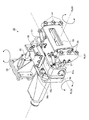
図5は、実施形態2に係る先端工具案内装置の全体を示す斜視図である。実施形態1に係る先端工具案内装置1の押付部材10Aは、下部ベース21と天井部105との間で突っ張ることにより、下部ベース21を水室仕切板106に押付けたが、本実施形態に係る先端工具案内装置2の押付部材10Bは、下部ベース21とホールドダウンリング107の固定爪107aとの間で突っ張ることにより、下部ベース21を水室仕切板106に押付ける点に特徴がある。なお、上述の実施形態と同一の効果を奏する構成には、同一の符号を付す。また、上述の実施形態と同一の構成及び効果は説明を省略する。
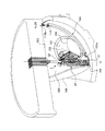
図6は、実施形態3に係る先端工具案内装置の全体を示す斜視図である。上述の実施形態に係る先端工具案内装置は、押付部材によって下部ベース21を拘束したが、本実施形態に係る先端工具案内装置3の補強部材10Cは、補強部材によってスライドテーブル30を拘束する点に特徴がある。なお、上述の実施形態と同一の効果を奏する構成には、同一の符号を付す。また、上述の実施形態と同一の構成及び効果は説明を省略する。
10A 押付部材
10Aa 下部ベース側端部
10Ab 天井面側端部
10B 押付部材
10Ba 下部ベース側端部
10Bb ホールドダウンリング側端部
10Bc 嵌合部
10C 補強部材
11Ca スライドテーブル側端部
11Cb ホールドダウンリング側端部
11A 押付シリンダ
11B ジャッキボルト
20 旋回支持部
21 下部ベース
21a 水室仕切板側接触面
21b 押付部材側接触面
22 旋回部
23 上部支持部
30 スライドテーブル
31 テーブル部
31a 旋回支持部側端部
31b スライドテーブル支持部側端部
32 スライド部
33 第1ツールチェンジャ
34 スライドテーブル支持部
34a スライドテーブル側端部
34b 旋回支持部側端部
40 マニピュレータ
40a スライドテーブル側端部
40b 先端工具側端部
41 第2ツールチェンジャ
50 先端工具
51 工具本体
52 マニピュレータ取付部
53 ショット射出口
54 全方向転動ローラ
55 エアシリンダ
56 第1保持部材
56a 第1回動連結部材
57 第2保持部材
57a 第2回動連結部材
58 第3保持部材
58a 第3回動連結部材
60 制御装置
100 水室
101 管台
102 円筒管
103 処理面
104 底面部
105 天井部
106 水室仕切板
107 ホールドダウンリング
107a 固定爪
RL01 第1回動軸
RL02 第2回動軸
RL03 第3回動軸
RL04 回動軸
TL 旋回軸
VL01 仮想線
VL02 仮想線
Claims (10)
- 蒸気発生器の水室内に設けられている静止構造部材を押し付けて突っ張ることで前記水室内に支持されると共に、旋回軸を軸として旋回する旋回支持部と、
前記旋回支持部に可動部材を介して連結され、対象とする処理面に処理を施す先端工具と、
前記旋回支持部に働く力であって、前記旋回支持部の旋回方向に働く前記力に対抗するように前記旋回支持部を補強すると共に前記水室内に設けられる補強部材と、
を備えることを特徴とする先端工具案内装置。 - 前記水室を構成する静止構造部材は、互いに対向し合う天井部と底面部であり、前記旋回支持部は前記天井部と前記底面部とを前記旋回軸上に存在する土台部材を介して押し付けて突っ張ることで前記旋回支持部は前記水室内に支持され、前記土台部材は、前記水室内の静止構造部材と前記補強部材とで挟んで固定されることを特徴とする請求項1に記載の先端工具案内装置。
- 前記補強部材は、前記補強部材の長手方向に伸縮する押付手段を有し、前記補強部材の一方の端部と前記天井部との間に働く摩擦力が前記補強部材の一方の端部に働く前記天井部に沿う方向の力よりも大きい状態で前記補強部材の一方の端部が前記天井部に対し接触すると共に、他方の端部が前記土台部材の一方の側面に対して垂直に接触し、前記土台部材の前記一方の側面と対向する前記土台部材の側面は、前記水室を区分けする静止構造部材の水室仕切板に接触することを特徴とする請求項2に記載の先端工具案内装置。
- 前記水室内に設けられているホールドダウンリングに蓋部材を固定する固定爪は前記静止構造部材であり、前記土台部材の一方の側面は、前記水室を区分けする水室仕切板に接触し、前記補強部材は、一方の端部が前記固定爪に嵌め合わされると共に他方の端部が前記土台部材の一方の側面とは反対側の側面に対して前記水室仕切板側に向かって接触することを特徴とする請求項2に記載の先端工具案内装置。
- 前記補強部材は、前記補強部材の長手方向に伸縮する押付手段を有することを特徴とする請求項4に記載の先端工具案内装置。
- 前記補強部材は、前記旋回支持部の前記旋回軸から所定の距離を有すると共に前記旋回支持部に連結される部位に設けられ、前記旋回支持部の前記旋回軸を含む仮想の面に対して所定の角度を有して端部が前記静止構造部材に接触することを特徴とする請求項1に記載の先端工具案内装置。
- 前記補強部材は複数設けられ、前記複数の補強部材は前記旋回支持部の前記旋回軸を含む仮想の面に対して面対称な状態で前記端部が前記静止構造部材に接触することを特徴とする請求項6に記載の先端工具案内装置。
- 前記補強部材は2つ設けられ、前記2つの補強部材の端部のうち、前記静止構造部材側のそれぞれの端部間の距離は、前記旋回支持部の前記旋回軸側のそれぞれの端部間の距離よりも大きいことを特徴とする請求項6または請求項7に記載の先端工具案内装置。
- 前記補強部材は、前記旋回支持部の前記旋回軸から所定の距離を有すると共に前記旋回支持部に連結される前記部位に対して回動できるように支持されることを特徴とする請求項6から請求項8のいずれか一項に記載の先端工具案内装置。
- 前記旋回支持部に連結されるテーブル部と、
前記テーブル部上をスライド移動すると共に前記先端工具を前記処理面に誘導するマニピュレータが装着されるスライド部と、
から構成されるスライドテーブルを備え、前記補強部材は、前記旋回支持部の旋回軸から所定の距離を有する部位である前記スライドテーブルに設けられることを特徴とする請求項6から請求項9のいずれか一項に記載の先端工具案内装置。
Priority Applications (6)
| Application Number | Priority Date | Filing Date | Title |
|---|---|---|---|
| JP2008060732A JP5118515B2 (ja) | 2008-03-11 | 2008-03-11 | 先端工具案内装置 |
| PCT/JP2009/053452 WO2009113398A1 (ja) | 2008-03-11 | 2009-02-25 | 先端工具案内装置 |
| US12/918,738 US8297093B2 (en) | 2008-03-11 | 2009-02-25 | Tip tool guide apparatus |
| KR1020107019496A KR101255888B1 (ko) | 2008-03-11 | 2009-02-25 | 선단 공구 안내 장치 |
| EP09720058.8A EP2253883B1 (en) | 2008-03-11 | 2009-02-25 | Device for guiding front end tool |
| CN2009801084410A CN101970936B (zh) | 2008-03-11 | 2009-02-25 | 前端工具导向装置 |
Applications Claiming Priority (1)
| Application Number | Priority Date | Filing Date | Title |
|---|---|---|---|
| JP2008060732A JP5118515B2 (ja) | 2008-03-11 | 2008-03-11 | 先端工具案内装置 |
Publications (2)
| Publication Number | Publication Date |
|---|---|
| JP2009216310A JP2009216310A (ja) | 2009-09-24 |
| JP5118515B2 true JP5118515B2 (ja) | 2013-01-16 |
Family
ID=41065067
Family Applications (1)
| Application Number | Title | Priority Date | Filing Date |
|---|---|---|---|
| JP2008060732A Active JP5118515B2 (ja) | 2008-03-11 | 2008-03-11 | 先端工具案内装置 |
Country Status (6)
| Country | Link |
|---|---|
| US (1) | US8297093B2 (ja) |
| EP (1) | EP2253883B1 (ja) |
| JP (1) | JP5118515B2 (ja) |
| KR (1) | KR101255888B1 (ja) |
| CN (1) | CN101970936B (ja) |
| WO (1) | WO2009113398A1 (ja) |
Families Citing this family (7)
| Publication number | Priority date | Publication date | Assignee | Title |
|---|---|---|---|---|
| FR2914979B1 (fr) * | 2007-04-12 | 2009-07-10 | Saipem S A Sa | Procede de realisation de conduite sous-marine comprenant le martelage de soudures d'assemblage a l'interieur de la conduite |
| JP5461145B2 (ja) * | 2009-10-30 | 2014-04-02 | 三菱重工業株式会社 | マニピュレータの制御方法及び管台内作業方法 |
| JP5634073B2 (ja) * | 2010-01-15 | 2014-12-03 | 三菱重工業株式会社 | 水室内作業装置および水室内作業方法 |
| JP5314609B2 (ja) * | 2010-01-27 | 2013-10-16 | 三菱重工業株式会社 | 水室内作業装置 |
| JP2015017808A (ja) * | 2013-07-08 | 2015-01-29 | 株式会社東芝 | 燃料集合体の上部タイプレートの把持装置および把持方法 |
| US10480874B2 (en) * | 2016-08-25 | 2019-11-19 | Stoneage, Inc. | Pro-boxer flexible lance positioner apparatus |
| CN113279826B (zh) * | 2021-06-22 | 2022-03-25 | 中国核动力研究设计院 | 一种适用于汽轮机管道内异物作业工具的导向支撑装置 |
Family Cites Families (6)
| Publication number | Priority date | Publication date | Assignee | Title |
|---|---|---|---|---|
| US4216893A (en) * | 1977-03-08 | 1980-08-12 | Westinghouse Electric Corp. | Apparatus for remotely repairing tubes in a steam generator |
| JPS57124297A (en) * | 1981-01-26 | 1982-08-03 | Meidensha Electric Mfg Co Ltd | Room working device for atomic power plant facility |
| JPS57124296A (en) * | 1981-01-26 | 1982-08-03 | Meidensha Electric Mfg Co Ltd | Room working device for atomic power plant facility |
| DE3122660C2 (de) * | 1981-06-06 | 1986-06-19 | Brown Boveri Reaktor GmbH, 6800 Mannheim | Einrichtung zur Inspektion und/oder zur Reparatur der Rohre eines Dampferzeugers einer Kernkraftanlage |
| CN2181066Y (zh) * | 1993-12-07 | 1994-10-26 | 上海核工程研究设计院 | 压水堆核电站蒸汽发生器垂直支柱结构 |
| JP4865334B2 (ja) * | 2006-01-10 | 2012-02-01 | 三菱重工業株式会社 | 先端工具案内装置及び先端工具案内装置の搬入方法 |
-
2008
- 2008-03-11 JP JP2008060732A patent/JP5118515B2/ja active Active
-
2009
- 2009-02-25 US US12/918,738 patent/US8297093B2/en active Active
- 2009-02-25 EP EP09720058.8A patent/EP2253883B1/en active Active
- 2009-02-25 WO PCT/JP2009/053452 patent/WO2009113398A1/ja not_active Ceased
- 2009-02-25 KR KR1020107019496A patent/KR101255888B1/ko active Active
- 2009-02-25 CN CN2009801084410A patent/CN101970936B/zh active Active
Also Published As
| Publication number | Publication date |
|---|---|
| EP2253883B1 (en) | 2016-05-25 |
| JP2009216310A (ja) | 2009-09-24 |
| EP2253883A1 (en) | 2010-11-24 |
| WO2009113398A1 (ja) | 2009-09-17 |
| KR20100114534A (ko) | 2010-10-25 |
| CN101970936A (zh) | 2011-02-09 |
| EP2253883A4 (en) | 2014-03-12 |
| US20100326157A1 (en) | 2010-12-30 |
| KR101255888B1 (ko) | 2013-04-17 |
| US8297093B2 (en) | 2012-10-30 |
| CN101970936B (zh) | 2012-12-26 |
Similar Documents
| Publication | Publication Date | Title |
|---|---|---|
| JP5118515B2 (ja) | 先端工具案内装置 | |
| US8713775B2 (en) | Apparatus and method for servicing dynamoelectric machine components in-situ | |
| EP2705934A2 (en) | A method and a device for change of rigidity of a serial or parallel basic movable mechanism, especially of industrial robots and machining machines | |
| JP5688383B2 (ja) | シュラウドサポートの補修方法及びその補修装置 | |
| US11141869B2 (en) | Robot-arm harness connection structure and multi-joined welding robot | |
| US20140123680A1 (en) | Modular drop-in combustor assembly for industial gas turbine and method for installation | |
| JP5634073B2 (ja) | 水室内作業装置および水室内作業方法 | |
| JP2010078433A (ja) | 遠隔作業装置 | |
| KR20120129525A (ko) | 6자유도 병렬 기구 | |
| EP2962805B1 (en) | Water jet peening device | |
| JP2022172308A (ja) | 往復移動装置 | |
| KR101859427B1 (ko) | 원자로 증기발생기의 노즐댐 설치 및 제거용 로봇장치 | |
| JP2018075647A (ja) | マニピュレータ装置 | |
| CN107745284B (zh) | 加工中心机构 | |
| JP2011189475A (ja) | 加工機 | |
| US20190202050A1 (en) | Robot fixing system and robot | |
| KR102296242B1 (ko) | 원자로헤드 내부관통관의 용접부 가공장치 | |
| US12528144B2 (en) | Table device | |
| US20210254300A1 (en) | Pile installation system for an offshore foundation construction and method of installing a pile | |
| JP2017001146A (ja) | 加工機 | |
| JP5675118B2 (ja) | 水室内作業装置の設置方法 | |
| JP6245666B2 (ja) | 原子炉炉心シュラウドの検査、改造または修理のための装置および方法 | |
| JP5919107B2 (ja) | 設備機器の転倒防止装置 | |
| JP4447437B2 (ja) | 溶接装置 | |
| JP2012163292A (ja) | 管群外筒の組立方法及び蒸気発生器の組立方法、管群外筒の移動装置 |
Legal Events
| Date | Code | Title | Description |
|---|---|---|---|
| A621 | Written request for application examination |
Free format text: JAPANESE INTERMEDIATE CODE: A621 Effective date: 20110128 |
|
| TRDD | Decision of grant or rejection written | ||
| A01 | Written decision to grant a patent or to grant a registration (utility model) |
Free format text: JAPANESE INTERMEDIATE CODE: A01 Effective date: 20120925 |
|
| A01 | Written decision to grant a patent or to grant a registration (utility model) |
Free format text: JAPANESE INTERMEDIATE CODE: A01 |
|
| A61 | First payment of annual fees (during grant procedure) |
Free format text: JAPANESE INTERMEDIATE CODE: A61 Effective date: 20121019 |
|
| R151 | Written notification of patent or utility model registration |
Ref document number: 5118515 Country of ref document: JP Free format text: JAPANESE INTERMEDIATE CODE: R151 |
|
| FPAY | Renewal fee payment (event date is renewal date of database) |
Free format text: PAYMENT UNTIL: 20151026 Year of fee payment: 3 |
|
| R250 | Receipt of annual fees |
Free format text: JAPANESE INTERMEDIATE CODE: R250 |