JP5118533B2 - Syringe needle set - Google Patents
Syringe needle set Download PDFInfo
- Publication number
- JP5118533B2 JP5118533B2 JP2008086696A JP2008086696A JP5118533B2 JP 5118533 B2 JP5118533 B2 JP 5118533B2 JP 2008086696 A JP2008086696 A JP 2008086696A JP 2008086696 A JP2008086696 A JP 2008086696A JP 5118533 B2 JP5118533 B2 JP 5118533B2
- Authority
- JP
- Japan
- Prior art keywords
- injection needle
- needle
- position defining
- injection
- penetrating member
- Prior art date
- Legal status (The legal status is an assumption and is not a legal conclusion. Google has not performed a legal analysis and makes no representation as to the accuracy of the status listed.)
- Expired - Fee Related
Links
- 238000002347 injection Methods 0.000 claims description 99
- 239000007924 injection Substances 0.000 claims description 99
- 230000000149 penetrating effect Effects 0.000 claims description 45
- 230000001070 adhesive effect Effects 0.000 claims description 26
- 239000000853 adhesive Substances 0.000 claims description 25
- 229920001971 elastomer Polymers 0.000 claims description 5
- 210000003491 skin Anatomy 0.000 description 24
- 239000000243 solution Substances 0.000 description 15
- 239000003814 drug Substances 0.000 description 10
- 229940079593 drug Drugs 0.000 description 10
- 238000012986 modification Methods 0.000 description 8
- 230000004048 modification Effects 0.000 description 8
- 210000004207 dermis Anatomy 0.000 description 5
- 210000002615 epidermis Anatomy 0.000 description 5
- 238000000034 method Methods 0.000 description 5
- 230000001681 protective effect Effects 0.000 description 5
- 239000000126 substance Substances 0.000 description 5
- 238000010254 subcutaneous injection Methods 0.000 description 4
- 239000007929 subcutaneous injection Substances 0.000 description 4
- 230000035515 penetration Effects 0.000 description 3
- 239000007788 liquid Substances 0.000 description 2
- 210000003205 muscle Anatomy 0.000 description 2
- 230000004304 visual acuity Effects 0.000 description 2
- NIXOWILDQLNWCW-UHFFFAOYSA-N acrylic acid group Chemical group C(C=C)(=O)O NIXOWILDQLNWCW-UHFFFAOYSA-N 0.000 description 1
- 229920005549 butyl rubber Polymers 0.000 description 1
- 238000005520 cutting process Methods 0.000 description 1
- 238000010586 diagram Methods 0.000 description 1
- 238000009826 distribution Methods 0.000 description 1
- 229920006248 expandable polystyrene Polymers 0.000 description 1
- 239000011888 foil Substances 0.000 description 1
- 239000012943 hotmelt Substances 0.000 description 1
- 238000001802 infusion Methods 0.000 description 1
- 239000000463 material Substances 0.000 description 1
- 239000008155 medical solution Substances 0.000 description 1
- 235000015097 nutrients Nutrition 0.000 description 1
- 229920001296 polysiloxane Polymers 0.000 description 1
- 229920002379 silicone rubber Polymers 0.000 description 1
- 239000004945 silicone rubber Substances 0.000 description 1
- 239000007779 soft material Substances 0.000 description 1
- 239000011122 softwood Substances 0.000 description 1
- 238000003860 storage Methods 0.000 description 1
- 238000007920 subcutaneous administration Methods 0.000 description 1
- 230000008961 swelling Effects 0.000 description 1
- 238000003466 welding Methods 0.000 description 1
Images


Landscapes
- Infusion, Injection, And Reservoir Apparatuses (AREA)
Description
本発明は、薬液を注射する注射針セットに関し、特に、使用する注射針の穿刺深さを規定することのできる注射針セットに関する。 The present invention relates to an injection needle set for injecting a drug solution, and more particularly to an injection needle set capable of defining a puncture depth of an injection needle to be used.
人間の皮膚は、表面側から表皮、真皮、脂肪層及び筋肉組織が形成されており、皮内注射は表皮又は真皮に注射をし、皮下注射は脂肪層に注射をする。皮内注射及び皮下注射は、薬液の種類や注射の目的に応じて選択される。 In the human skin, the epidermis, dermis, fat layer and muscle tissue are formed from the surface side. Intradermal injection injects into the epidermis or dermis, and subcutaneous injection injects into the fat layer. Intradermal injection and subcutaneous injection are selected according to the type of medicinal solution and the purpose of injection.
表皮、真皮及び脂肪層は比較的薄いことから、所望の皮下又は皮内に注射することは非熟練者にとっては必ずしも簡便ではない。 Since the epidermis, dermis and fat layer are relatively thin, it is not always convenient for non-experts to inject the desired subcutaneous or intradermal.
このような背景から、注射針の皮膚方向への進行を所定のストッパによって制限して、穿刺深さを規定することのできる注射器が提案されている(例えば、特許文献1又は特許文献2参照)。 From such a background, a syringe that can regulate the puncture depth by restricting the progress of the injection needle in the skin direction with a predetermined stopper has been proposed (for example, see Patent Document 1 or Patent Document 2). .
前記の特許文献1及び特許文献2記載の注射器では、注射針の穿刺深さについては規定できて好適であるが、注射をしている最中の注射器は不安定であり、穿刺深さが一定に保たれない懸念がある。
In the syringes described in Patent Document 1 and
したがって、例えば視力が弱く、又は手先が器用でない患者が自分で薬液を注射する場合や、薬液を長時間(例えば数日)にわたって安定状態で注射することは困難である。 Therefore, for example, it is difficult for a patient with weak visual acuity or a person who is not dexterous to inject a drug solution by himself or to inject a drug solution in a stable state for a long time (for example, several days).
本発明はこのような課題を考慮してなされたものであり、操作が簡便で、しかも注射針を長時間安定して、適正な穿刺深さに維持することのできる注射針セットを提供することを目的とする。 The present invention has been made in consideration of such problems, and provides an injection needle set that is easy to operate, and that can stably maintain the injection needle at an appropriate puncture depth for a long period of time. With the goal.
本発明に係る注射針セットは、注射針体及び針位置規定部材を備える注射針セットであって、前記注射針体は、注射針と、前記針位置規定部材に当接する位置決ストッパと、前記注射針の側面に設けられ、斜め基端側に向けて突出する返し部材とを有し、前記針位置規定部材は、前記注射針が貫通可能な貫通部材と、皮膚と当接する面に設けられた粘着剤とを有し、前記注射針が前記貫通部材を貫通して、前記位置決ストッパが前記針位置規定部材の所定箇所に当接して位置決めされたとき、前記返し部材は前記貫通部材に係合することを特徴とする。 An injection needle set according to the present invention is an injection needle set including an injection needle body and a needle position defining member, and the injection needle body includes an injection needle, a positioning stopper that contacts the needle position defining member, A return member provided on a side surface of the injection needle and projecting toward the oblique base end side, and the needle position defining member is provided on a penetrating member through which the injection needle can penetrate and a surface in contact with the skin. And the adhesive needle penetrates the penetrating member, and the positioning stopper is positioned in contact with a predetermined position of the needle position defining member, the return member is attached to the penetrating member. It is characterized by engaging.
このような針位置規定部材は、粘着剤によって皮膚に対して安定して固定される。注射針は、簡便な操作で、位置決ストッパが針位置規定部材の所定箇所に当接して位置決めされ、しかも返し部材が貫通部材に係合することから抜去方向にずれることがないため、長時間安定して、適正な穿刺深さに維持することができる。 Such a needle position defining member is stably fixed to the skin with an adhesive. The injection needle is positioned by a simple operation with the positioning stopper in contact with a predetermined position of the needle position defining member, and since the return member is engaged with the penetrating member, it does not shift in the removal direction. It can be stably maintained at an appropriate puncture depth.
前記貫通部材はゴム体であると、注射針の貫通及び返し部材の係合に好適であり、しかも廉価である。 If the penetrating member is a rubber body, it is suitable for penetrating the injection needle and engaging the return member, and it is inexpensive.
前記針位置規定部材は皮膚に対して斜めに当接するように、先端面が軸心方向に対して非直角に形成されていてもよい。これにより、手技の種類や目的に応じて斜めに注射することができる。 The needle position defining member may have a tip surface formed non-perpendicular with respect to the axial direction so as to be in contact with the skin obliquely. Thereby, it can inject diagonally according to the kind and purpose of the procedure.
前記貫通部材と前記粘着剤との間には、前記注射針が挿通する孔を備えるフランジが設けられていてもよい。このようなフランジにより、注射針を安定して皮膚に当接させることができる。 A flange having a hole through which the injection needle is inserted may be provided between the penetrating member and the adhesive. With such a flange, the injection needle can be stably brought into contact with the skin.
前記フランジは、前記孔の周囲が前記皮膚の方向に向かって膨出していてもよい。フランジにおける孔の周囲が皮膚の方向に向かって膨出していることにより、針位置規定部材と皮膚との密着性が向上する。 The flange may bulge around the hole toward the skin. Since the periphery of the hole in the flange bulges toward the skin, the adhesion between the needle position defining member and the skin is improved.
前記貫通部材には、該注射針を導くガイド孔が設けられていてもよい。このようなガイド孔によれば、注射針を適正位置で適正方向に案内するこができ、しかも注射針が貫通部材を貫通しやすい。 The penetrating member may be provided with a guide hole for guiding the injection needle. According to such a guide hole, the injection needle can be guided in an appropriate direction at an appropriate position, and the injection needle can easily penetrate the penetrating member.
本発明に係る注射針セットでは、針位置規定部材が粘着剤によって皮膚に対して安定して固定される。一方、注射針は、簡便な操作で、位置決ストッパが針位置規定部材の所定箇所して位置決めされ、しかも返し部材が貫通部材に係合することから抜去方向にずれることがないため、長時間安定して、適正な穿刺深さに維持することができる。 In the injection needle set according to the present invention, the needle position defining member is stably fixed to the skin by the adhesive. On the other hand, since the positioning needle is positioned at a predetermined position of the needle position defining member with a simple operation and the return member is engaged with the penetrating member, the injection needle is not displaced in the removal direction. It can be stably maintained at an appropriate puncture depth.
以下、本発明に係る注射針セットについて実施の形態を挙げ、添付の図1〜図11を参照しながら説明する。以下の説明では、上方及び下方の向きについて図1及び図2に示す状態を基準とするが、実際の使用に際しては注射針セット10の向きは限定されない。また、図1及び図2における上方を基端側とする。
Hereinafter, an injection needle set according to the present invention will be described with reference to FIGS. In the following description, the upper and lower directions are based on the state shown in FIGS. 1 and 2, but the direction of the
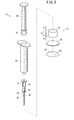
図1及び図2に示すように、注射針セット10は、注射器(注射針体)12と、針位置規定部材14とを有する。注射器12と針位置規定部材14は、必ずしも流通及び保管する段階でセットになっていなくとも、使用段階でセットとして用いられればよい。
As shown in FIGS. 1 and 2, the injection needle set 10 includes a syringe (injection needle body) 12 and a needle
針位置規定部材14は、貫通部材22と、皮膚と当接する下面に設けられた粘着剤26と、該粘着剤26の下側の粘着面に貼られる保護フィルム28とを有する。
The needle
貫通部材22は、後述する注射針16が貫通可能な材質で、例えばゴム体(シリコーンゴム、ブチルゴム等)であると、注射針16の貫通及び返し部材の係合に好適であり、しかも廉価である。貫通部材22は、ゴム体以外にも、硬質の発泡スチロール又は軟質の木材等を利用可能である。
The penetrating
貫通部材22は、円筒形状であって、皮膚に当接するときに安定するように適度に大径である。
The penetrating
粘着剤26は、注射針16が貫通可能な薄く柔らかい材質で、貫通部材22よりも大径(例えば略2倍の径)であり、該貫通部材22に固定されている。粘着剤26としては、ゴム系、アクリル系、シリコーン系などの粘着剤が使用される。感圧性ホットメルトタイプ、架橋タイプなどがある。形状についは、円、楕円、星形など穿刺部位が理解しやすい形状にするよい。粘着剤26の下面は、粘着面となっており、初期状態では保護フィルム28が貼られていて、粘着性が保持されている。保護フィルム28は、粘着剤26から剥がしやすいように、小さいピールタブ29が膨出している。
The
注射器12は、本体のシリンジ15と、該シリンジ15に連通するように設けられた注射針16と、シリンジ15に充填される薬液17を注射針16に導出するプランジャ20とを有する。シリンジ15は透明であり、側面に目盛りが設けられている。薬液17は広義であり、栄養剤等を含む。シリンジ15及びプランジャ20は、一般の注射器で用いられているものである。
The
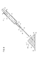
図3に示すように、注射針16は、中空であり、針本体30と、該針本体30を支持してシリンジ15に接続するハブ32と、該ハブ32の先端に設けられた小円形のストッパフランジ34と、針本体30の側面に設けられた返し部材36とを有する。注射針16は、ハブ32によってシリンジ15にルアー接続される。注射針16はテーパ針でもよい。
As shown in FIG. 3, the
ストッパフランジ34は、注射器12による穿刺をする際に、針位置規定部材14の上面に当接する位置決ストッパであり、これにより針本体30の穿刺深さが正確に規定される。位置決ストッパは、針位置規定部材14の所定箇所に当接して注射針16の位置決めが可能であればよく、例えばシリンジ15から延在する部材によって代用してもよい。
The
図3及び図4に示すように、返し部材36は、薄箔で構成されており、斜め基端側に向けて突出する複数の突起38を有する。返し部材36は、ストッパフランジ34を基準としてL1の箇所に設けられている。このL1は、貫通部材22の厚さL2の半分程度にすると安定してよい。針本体30の長さがL3であると、L3−L2(厳密には、粘着剤26の厚みや、貫通部材22の変形量等も考慮するとよい。)が生体に対する穿刺深さとなる。返し部材36は、例えばレーザ溶着によって針本体30に固定されている。
As shown in FIGS. 3 and 4, the
注射針16が貫通部材22を貫通して、ストッパフランジ34が針位置規定部材14の上面に当接して位置決めされたとき、返し部材36は貫通部材22に食い込んで係合し、注射針16の抜け止めとなる。
When the
返し部材36は、斜め基端側に向けて突出する部分を有していればよく、例えば、図5に示すように、針本体30の側面を適度に切り込んで発生するバリ42を用いてもよい。
The
図1〜図3に明らかなように、注射針セット10は簡便構造である。注射針セット10は予め滅菌され、あるいは実質的に無菌状態で作製されて、該滅菌状態あるいは無菌状態が維持されるように包装されており、使用後には所定の方法で廃棄される、いわゆるディスポーザブル品である。注射器12と針位置規定部材14は個別に包装されていてもよい。
As apparent from FIGS. 1 to 3, the injection needle set 10 has a simple structure. The injection needle set 10 is sterilized in advance or made in a substantially aseptic condition, and is packaged so as to maintain the sterilized condition or the aseptic condition, and is discarded after use by a predetermined method. It is a product. The
次に、このように構成される注射針セット10の作用について説明する。 Next, the operation of the injection needle set 10 configured as described above will be described.
先ず、ピールタブ29を持って保護フィルム28を粘着剤26から剥がし、皮膚の所定箇所に貼り付ける。針位置規定部材14は、粘着剤26の粘着作用と、適度に広い面積の貫通部材22によって安定し、皮膚に密着して固定される。
First, the
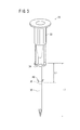
次いで、図6に示すように、ストッパフランジ34が針位置規定部材14の上面に当接するまで注射器12を押し下げる。これにより、注射針16は、貫通部材22を貫通し、粘着剤26を貫通して皮膚に穿刺される。例えば、皮下注射をする場合には、注射針16の先端は、さらに皮膚の表皮60、真皮62を通って脂肪層64に達するが、筋肉組織66までは達することがなく、穿刺深さが適正長となったところで停止する。
Next, as shown in FIG. 6, the
注射針16は、返し部材36が貫通部材22に食い込んで係合し、抜去方向にずれることがなく安定する。つまり、注射針16は、進行方向及び抜去方向のいずれの方向へもストッパフランジ34及び返し部材36でずれを防止できる。注射針16は、貫通部材22によって適度に圧迫されており、摩擦力を受けて一層安定する。
The
さらに、図7に示すように、プランジャ20を適度に押し下げる。これにより、薬液17は、注射針16に導出されて、生体内に注入される。ここで、注射針セット10は粘着剤26の作用により安定し、注射針16の穿刺深さは適正に保持されていることから、所望の深さに規定量の薬液17を注入することができる。また、粘着剤26が漏れ止めとなり、薬液17を正確に注入できる。
Furthermore, as shown in FIG. 7, the
特に、皮下注射の場合には、注射針16の先端は表皮60又は真皮62の深さまでしか達しないので皮膚の表面までの距離が短いが、粘着剤26が皮膚に密着して覆っているので漏れ止めの作用を奏し、薬液17が皮膚表面に漏れ出ることがなく、規定量の薬液17を正確に注射することができる。
In particular, in the case of subcutaneous injection, the tip of the
さらにまた、注射針16は、針位置規定部材14によって長時間安定して、適正な穿刺深さに維持されることから、注射をゆっくり確実に行うことができ、微量ずつ長時間の注液操作に適する。
Furthermore, since the
したがって、図8に示すように、注射針16には、チューブ70を介してシリンジポンプ72を接続しておき、長時間に微量ずつ薬液17を注入してもよい。もちろん、点滴等にも適用可能である。注射針16は、留置針(カテーテル)等でもよい。
Therefore, as shown in FIG. 8, a
この後、注射器12及び針位置規定部材14を皮膚から取り外して一連の注射の手技を終了する。
Thereafter, the
次に、針位置規定部材14の変形例について説明する。各変形例において、針位置規定部材14と同じ構成要素については同符号を付してその詳細な説明を省略する。
Next, a modified example of the needle
図9に示すように、第1の変形例に係る針位置規定部材14aは、皮膚に対して斜めに当接するように、貫通部材22の先端面が軸心J方向に対して非直角に形成されている。このような注射針セット10では手技の種類や目的に応じて斜めに注射することができる。斜めに穿刺をすることにより、穿刺深さの調整が容易になる。
As shown in FIG. 9, in the needle
また、針位置規定部材14aにおける貫通部材22には、軸心Jに沿って注射針16を導くガイド孔74が設けられている。このようなガイド孔74によれば、注射針16を適正位置で適正方向に案内するこができ、しかも注射針16が貫通部材22を貫通しやすい。
The penetrating
ガイド孔74は、開口部がやや広くて注射針16を導入しやすく、その他の部分は注射針16よりも細径であり、隙間なく正確に注射針16を案内することができ、特に針位置規定部材14aのように注射針16を斜めに操作する際に好適である。
The
ガイド孔74は、例えば貫通部材22の途中の距離L1の箇所まで延在していればよい。返し部材36が係合する箇所は、貫通部材22におけるガイド孔74の存在する箇所でもよいし、その他の箇所でもよい。ガイド孔74は、一定径である必要はなく、先細り形状等でもよい。ガイド孔74は貫通孔でもよい。ガイド孔74は注射針16を案内できるものであればよく、極細径又は実質的な面積がなく、孔として認識されないものであってもよい。ガイド孔74は、少なくとも一部が注射針16より細径であればよい。
The
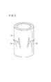
図10に示すように、第2の変形例に係る針位置規定部材14bは、貫通部材22に対して先細り円錐形状の切れ目76が設けられている。このような針位置規定部材14bでは、一連の注射の手技が終了した後に、上端の接続部78を切って内側部分80を先行的に取り除くことができ、注射器12を外しやすい。
As shown in FIG. 10, the needle
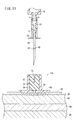
図11に示すように、第3の変形例に係る針位置規定部材14cは、貫通部材22の周囲を覆う硬質の筒体82と、貫通部材22及び筒体82の先端に設けられたフランジ84とを有する。粘着剤26は、フランジ84の下面に設けられている。
As shown in FIG. 11, the needle
筒体82によれば、貫通部材22を保護することができるとともに、該筒体82の上面にストッパフランジ34を当接させて位置決めをすることにより、位置決め精度が一層向上する。
According to the
フランジ84は、中央部に設けられた注射針16が挿通する小さい孔86と、該孔86の周囲が皮膚の方向に向かってわずかに膨出した膨出部88とを有する。孔86の周囲の膨出部88が皮膚の方向に向かって膨出していることにより、該膨出部88が穿刺箇所を適度に圧迫して密着性が向上する。フランジ84と貫通部材22は隙間なく接している。このようなフランジ84により、針位置規定部材14cを安定して皮膚に当接させることができる。
The
筒体82及びフランジ84を設けることにより、貫通部材22は小さくしても、針位置規定部材14cの全体としては安定する。
By providing the
上述したように、本実施の形態に係る注射針セット10では、針位置規定部材14が、粘着剤26によって皮膚に対して安定して固定される。貫通部材22に対して注射針16を押し込む簡便な操作により、ストッパフランジ34が針位置規定部材14の上面に当接して位置決めされ、しかも返し部材36が貫通部材22に係合することから抜去方向にずれることがないため、注射針16は長時間安定して、適正な穿刺深さに維持することができる。注射針セット10は、簡便な構造である。
As described above, in the injection needle set 10 according to the present embodiment, the needle
注射針セット10は、簡便な操作で適量の薬液を器具内に正確に注入することができ、例えば視力が弱く、又は手先が器用でない患者が自分で薬液を注射することもできる。 The injection needle set 10 can accurately inject an appropriate amount of drug solution into the instrument with a simple operation. For example, a patient with weak visual acuity or a dexterous hand can inject the drug solution himself.
針位置規定部材14、14a〜14cは、それぞれの特徴部を組み合わせて用いてもよいことはもちろんである。注射器12は、薬液17が予め規定量だけ充填されたプレフィルド式であってもよい。
Needless to say, the needle
本発明に係る注射器は、上述の実施の形態に限らず、本発明の要旨を逸脱することなく、種々の構成を採り得ることはもちろんである。 The syringe according to the present invention is not limited to the above-described embodiment, and it is needless to say that various configurations can be adopted without departing from the gist of the present invention.
10…注射針セット 12…注射器
14、14a〜14c…針位置規定部材 15…シリンジ
16…注射針 17…薬液
22…貫通部材 26…粘着剤
28…保護フィルム 30…針本体
32…ハブ 34…ストッパフランジ
36…返し部材 38…突起
74…ガイド孔 84…フランジ
88…膨出部
DESCRIPTION OF
Claims (6)
前記注射針体は、注射針と、
前記針位置規定部材に当接する位置決ストッパと、
前記注射針の側面に設けられ、斜め基端側に向けて突出する返し部材と、
を有し、
前記針位置規定部材は、前記注射針が接触しながら貫通可能な貫通部材と、
前記貫通部材又は前記貫通部材を保持する部材に対して動かないように固定され、皮膚と当接する面に設けられた粘着剤と、
を有し、
前記注射針が前記貫通部材を貫通して、前記位置決ストッパが前記針位置規定部材の所定箇所に当接して位置決めされたとき、前記返し部材は前記貫通部材の内部で前記貫通部材に係合することを特徴とする注射針セット。 An injection needle set including an injection needle body and a needle position defining member,
The injection needle body includes an injection needle,
A positioning stopper that contacts the needle position defining member;
A return member provided on a side surface of the injection needle and projecting toward the oblique base end;
Have
The needle position defining member includes a penetrating member that can be penetrated while the injection needle is in contact with the needle position defining member;
An adhesive provided on a surface which is fixed so as not to move with respect to the penetrating member or the member holding the penetrating member and is in contact with the skin;
Have
When the injection needle penetrates the penetrating member and the positioning stopper is positioned by contacting a predetermined position of the needle position defining member, the return member is engaged with the penetrating member inside the penetrating member . An injection needle set characterized by:
前記貫通部材はゴム体であることを特徴とする注射針セット。 The injection needle set according to claim 1,
The injection needle set, wherein the penetrating member is a rubber body.
前記針位置規定部材は皮膚に対して斜めに当接するように、先端面が軸心方向に対して非直角に形成されていることを特徴とする注射針セット。 The injection needle set according to claim 1 or 2,
The needle set is characterized in that the needle position defining member is formed in a non-right angle with respect to the axial direction so that the needle position defining member is in contact with the skin obliquely.
前記貫通部材と前記粘着剤との間には、前記注射針が挿通する孔を備えるフランジが設けられていることを特徴とする注射針セット。 In the injection needle set of any one of Claims 1-3,
A syringe needle set comprising a flange having a hole through which the syringe needle is inserted between the penetrating member and the adhesive.
前記フランジは、前記孔の周囲が前記皮膚の方向に向かって膨出していることを特徴とする注射針セット。 The needle set according to claim 4 ,
The injection needle set according to claim 1, wherein the flange is bulged around the hole toward the skin.
前記貫通部材には、該注射針を導くガイド孔が設けられていることを特徴とする注射針セット。 In the injection needle set according to any one of claims 1 to 5,
An injection needle set, wherein the penetrating member is provided with a guide hole for guiding the injection needle.
Priority Applications (1)
| Application Number | Priority Date | Filing Date | Title |
|---|---|---|---|
| JP2008086696A JP5118533B2 (en) | 2008-03-28 | 2008-03-28 | Syringe needle set |
Applications Claiming Priority (1)
| Application Number | Priority Date | Filing Date | Title |
|---|---|---|---|
| JP2008086696A JP5118533B2 (en) | 2008-03-28 | 2008-03-28 | Syringe needle set |
Publications (2)
| Publication Number | Publication Date |
|---|---|
| JP2009233286A JP2009233286A (en) | 2009-10-15 |
| JP5118533B2 true JP5118533B2 (en) | 2013-01-16 |
Family
ID=41247977
Family Applications (1)
| Application Number | Title | Priority Date | Filing Date |
|---|---|---|---|
| JP2008086696A Expired - Fee Related JP5118533B2 (en) | 2008-03-28 | 2008-03-28 | Syringe needle set |
Country Status (1)
| Country | Link |
|---|---|
| JP (1) | JP5118533B2 (en) |
Families Citing this family (6)
| Publication number | Priority date | Publication date | Assignee | Title |
|---|---|---|---|---|
| DE102011119203A1 (en) * | 2011-11-16 | 2013-05-16 | Lts Lohmann Therapie-Systeme Ag | Cylinder-piston unit with short cannula |
| WO2014033898A1 (en) * | 2012-08-31 | 2014-03-06 | テルモ株式会社 | Syringe |
| CA3077738C (en) * | 2015-01-09 | 2022-08-16 | Becton, Dickinson And Company Limited | Infusion adapter |
| JP6734078B2 (en) * | 2016-03-10 | 2020-08-05 | 一般財団法人電力中央研究所 | Method for injecting into femoral bone marrow cavity, method for producing blood remodeling model animal, and puncture assisting instrument used therefor |
| US11690787B2 (en) | 2020-08-25 | 2023-07-04 | Becton, Dickinson And Company | Drug transfer adapter |
| CN115445017B (en) * | 2022-09-15 | 2024-06-14 | 温州市中西医结合医院 | Acupuncture point injection device for skin care of endocrine patient |
Family Cites Families (4)
| Publication number | Priority date | Publication date | Assignee | Title |
|---|---|---|---|---|
| JPS62119946U (en) * | 1986-01-24 | 1987-07-30 | ||
| JPH1043296A (en) * | 1996-08-05 | 1998-02-17 | Terumo Corp | Chemical injecting apparatus |
| JP4284583B2 (en) * | 2002-06-10 | 2009-06-24 | 味の素株式会社 | Puncture structure of liquid introduction needle and plug and liquid introduction needle |
| JP4768415B2 (en) * | 2005-11-24 | 2011-09-07 | テルモ株式会社 | Puncture device |
-
2008
- 2008-03-28 JP JP2008086696A patent/JP5118533B2/en not_active Expired - Fee Related
Also Published As
| Publication number | Publication date |
|---|---|
| JP2009233286A (en) | 2009-10-15 |
Similar Documents
| Publication | Publication Date | Title |
|---|---|---|
| JP5385260B2 (en) | Syringe | |
| JP6473132B2 (en) | Automatic tilting infusion set assembly | |
| US10729844B2 (en) | Angled inserter for drug infusion | |
| EP1984044B1 (en) | Infusion set | |
| JP4118399B2 (en) | Puncture adjusting tool for injection needle and injection needle assembly including the same | |
| JP5118533B2 (en) | Syringe needle set | |
| EP2531242B1 (en) | Dermal access device | |
| US8246578B2 (en) | Puncture device | |
| JP7677787B2 (en) | Method and device for introducing a needle for catheter placement - Patents.com | |
| CN102369034A (en) | Syringe needle assembly and medicament injection device | |
| JP2007111537A (en) | Safety infusion set | |
| US20140170594A1 (en) | Dual medicament carpule for dental syringes | |
| US20110160612A1 (en) | Pain free hypodermic needle | |
| US20060079844A1 (en) | Needle apparatus | |
| KR101699757B1 (en) | Assebled needle set for injecting a medicinal fluid | |
| JP2008110260A (en) | Tool for adjusting syringe needle punctures and syringe needle assembly with the same | |
| EP3919100A1 (en) | Indwelling subcutaneous administration needle | |
| HK1120235B (en) | Infusion set |
Legal Events
| Date | Code | Title | Description |
|---|---|---|---|
| A621 | Written request for application examination |
Free format text: JAPANESE INTERMEDIATE CODE: A621 Effective date: 20110117 |
|
| A131 | Notification of reasons for refusal |
Free format text: JAPANESE INTERMEDIATE CODE: A131 Effective date: 20120710 |
|
| A977 | Report on retrieval |
Free format text: JAPANESE INTERMEDIATE CODE: A971007 Effective date: 20120712 |
|
| A521 | Request for written amendment filed |
Free format text: JAPANESE INTERMEDIATE CODE: A523 Effective date: 20120905 |
|
| TRDD | Decision of grant or rejection written | ||
| A01 | Written decision to grant a patent or to grant a registration (utility model) |
Free format text: JAPANESE INTERMEDIATE CODE: A01 Effective date: 20121002 |
|
| A01 | Written decision to grant a patent or to grant a registration (utility model) |
Free format text: JAPANESE INTERMEDIATE CODE: A01 |
|
| A61 | First payment of annual fees (during grant procedure) |
Free format text: JAPANESE INTERMEDIATE CODE: A61 Effective date: 20121019 |
|
| R150 | Certificate of patent or registration of utility model |
Ref document number: 5118533 Country of ref document: JP Free format text: JAPANESE INTERMEDIATE CODE: R150 Free format text: JAPANESE INTERMEDIATE CODE: R150 |
|
| FPAY | Renewal fee payment (event date is renewal date of database) |
Free format text: PAYMENT UNTIL: 20151026 Year of fee payment: 3 |
|
| R250 | Receipt of annual fees |
Free format text: JAPANESE INTERMEDIATE CODE: R250 |
|
| R250 | Receipt of annual fees |
Free format text: JAPANESE INTERMEDIATE CODE: R250 |
|
| R250 | Receipt of annual fees |
Free format text: JAPANESE INTERMEDIATE CODE: R250 |
|
| R250 | Receipt of annual fees |
Free format text: JAPANESE INTERMEDIATE CODE: R250 |
|
| LAPS | Cancellation because of no payment of annual fees |