JP5118908B2 - Electric vacuum cleaner - Google Patents

Electric vacuum cleaner Download PDF

Info

Publication number
JP5118908B2
JP5118908B2 JP2007180447A JP2007180447A JP5118908B2 JP 5118908 B2 JP5118908 B2 JP 5118908B2 JP 2007180447 A JP2007180447 A JP 2007180447A JP 2007180447 A JP2007180447 A JP 2007180447A JP 5118908 B2 JP5118908 B2 JP 5118908B2
Authority
JP
Japan
Prior art keywords
dust
dust collection
collection chamber
vacuum cleaner
airtight member
Prior art date
Legal status (The legal status is an assumption and is not a legal conclusion. Google has not performed a legal analysis and makes no representation as to the accuracy of the status listed.)
Expired - Fee Related
Application number
JP2007180447A
Other languages
Japanese (ja)
Other versions
JP2009017903A (en
Inventor
剛一 長田
恵一 藤森
Current Assignee (The listed assignees may be inaccurate. Google has not performed a legal analysis and makes no representation or warranty as to the accuracy of the list.)
Hitachi Global Life Solutions Inc
Original Assignee
Hitachi Appliances Inc
Priority date (The priority date is an assumption and is not a legal conclusion. Google has not performed a legal analysis and makes no representation as to the accuracy of the date listed.)
Filing date
Publication date
Application filed by Hitachi Appliances Inc filed Critical Hitachi Appliances Inc
Priority to JP2007180447A priority Critical patent/JP5118908B2/en
Publication of JP2009017903A publication Critical patent/JP2009017903A/en
Application granted granted Critical
Publication of JP5118908B2 publication Critical patent/JP5118908B2/en
Expired - Fee Related legal-status Critical Current
Anticipated expiration legal-status Critical

Links

Images

Landscapes

  • Electric Suction Cleaners (AREA)

Description

本発明は電気掃除機に関するものである。   The present invention relates to a vacuum cleaner.

本発明は集塵室を覆うように設けられている蓋体との気密を保持するための気密部材の気密性の向上と、紙パックや集塵ケースと取り出す際の着脱性を向上させた電気掃除機に関するものである。   The present invention improves the airtightness of an airtight member for maintaining airtightness with a lid provided so as to cover the dust collection chamber, and improves the detachability when taking out a paper pack or dust collection case. It is about a vacuum cleaner.

紙パック又は集塵ケースを用いる電気掃除機では、捕獲した塵によって紙パックや集塵ケースが満杯になったとき、それらを取り外して使い捨て(新しい紙パックと交換)又は塵を捨てることができるので、取り扱いが便利である。   In a vacuum cleaner that uses a paper pack or dust collection case, when the paper pack or dust collection case is full due to the captured dust, it can be removed and replaced (replaced with a new paper pack) or discarded. Easy to handle.

しかし、紙パックや集塵ケースを取り外す際に、集塵室を覆うように設けられている蓋体との気密を保持するための気密部材は気密性を向上させるために、その一部が集塵室に張り出した弾性部材であることが多く、そのため紙パックや集塵ケースを取り外す際に、集塵室に張り出した気密部材に引っ掛かり取り出し難いため、取り出し易い気密部材の形状が提案されている。   However, when removing the paper pack or dust collection case, a part of the airtight member for maintaining airtightness with the lid provided to cover the dust collection chamber is collected to improve the airtightness. It is often an elastic member that protrudes into the dust chamber, so when removing a paper pack or dust collection case, it is difficult to take out the air-tight member that protrudes into the dust chamber, so that the shape of an air-tight member that can be easily removed has been proposed. .

集塵室にセットされている紙パックや集塵ケースは気密性を向上させるために形成されている気密部材の集塵室に張り出した形状に引っ掛かり、集塵室への着脱性が悪化していた。これらの着脱性を改善するために、例えば特許文献1(特開平11―76110号公報)のように、二重のリブを設け溝を形成し、その溝に弾性部材等で形成される気密部材を挿入し、気密部材の内側面と集塵室の内面を略面一とすることが提案されている。   The paper pack and dust collection case set in the dust collection chamber are hooked on the shape of the airtight member formed to improve the airtightness and project to the dust collection chamber, and the attachment / detachment to the dust collection chamber has deteriorated. It was. In order to improve these detachability, for example, as in Patent Document 1 (Japanese Patent Laid-Open No. 11-76110), a double rib is provided to form a groove, and an airtight member formed by an elastic member or the like in the groove It is proposed that the inner surface of the airtight member and the inner surface of the dust collecting chamber are substantially flush with each other.

特開平11−76110号公報JP-A-11-76110

しかしながら、上記の従来の構成(特許文献1)では、気密漏れが生じ易く電気掃除機の本来の役割であり、また最も重要視される吸込仕事率が低下してしまい、集塵効率が低下してしまう問題があった。   However, in the above-described conventional configuration (Patent Document 1), an airtight leak is likely to occur, which is the original role of the vacuum cleaner, and the most important suction work rate is reduced, and dust collection efficiency is reduced. There was a problem.

本発明の目的は、集塵室からの気密漏れを発生させない若しくは最小限に抑え、吸込仕事率の低下を抑えるとともに、集塵室からの紙パック又は集塵ケースの着脱性が良い電気掃除機を提供することにある。   An object of the present invention is to provide an electric vacuum cleaner that does not cause or minimizes airtight leakage from the dust collection chamber, suppresses a reduction in suction work efficiency, and has good detachability of the paper pack or dust collection case from the dust collection chamber Is to provide.

本発明は、電動送風機及び集塵室を備えた掃除機本体と、該掃除機本体に設けられ、前記集塵室を開閉自在に覆うように設けられた蓋体と、前記集塵室と前記蓋体とを気密に保持する気密部材を備えた電気掃除機において、前記気密部材は複数の突起部と、該突起部と一体に形成された緩衝部とを備え、前記集塵室は少なくともその外周部に垂直方向に立ち上がった少なくとも3つの隔壁を有し、前記気密部材のうち集塵室側に位置する部分は、前記少なくとも3つの隔壁のうち最も内側に位置する隔壁と略面一もしくは前記少なくとも3つの隔壁のうち最も内側に位置する隔壁よりも外側になるように位置させ、前記少なくとも3つの隔壁間には、少なくとも2つの溝部が形成され、該溝部には前記複数の突起部が挿入され、前記少なくとも3つの隔壁のうち最も外側に位置した隔壁は、前記複数の突起部と一体に形成された緩衝部で覆われたことを特徴とする。 The present invention includes a vacuum cleaner main body including an electric blower and a dust collection chamber, a lid provided in the vacuum cleaner main body so as to cover the dust collection chamber so as to be openable and closable, the dust collection chamber, In an electric vacuum cleaner provided with an airtight member that hermetically holds the lid, the airtight member includes a plurality of protrusions and a buffer part integrally formed with the protrusions, and the dust collecting chamber is at least And having at least three partition walls standing vertically on the outer periphery, and the portion of the hermetic member located on the dust collection chamber side is substantially flush with the innermost partition wall of the at least three partition walls , or The at least three partition walls are positioned outside the innermost partition wall , and at least two groove portions are formed between the at least three partition walls, and the plurality of protrusions are formed in the groove portions. Inserted and said less Partition wall which is located outermost among the even three partition walls is characterized in that it is covered by the plurality of protrusions and a buffer portion formed integrally.

本発明によれば、集塵室からの気密漏れを発生させない若しくは最小限に抑え、吸込仕事率の低下を抑えるとともに、集塵室からの紙パック又は集塵ケースの着脱性に優れた電気掃除機を提供することができる。   According to the present invention, an electric cleaning that does not cause or minimizes airtight leakage from the dust collection chamber, suppresses a reduction in suction work efficiency, and is excellent in detachability of the paper pack or dust collection case from the dust collection chamber. Machine can be provided.

本発明の第1の実施例について、図1から図3を引用して説明する。   A first embodiment of the present invention will be described with reference to FIGS.

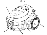
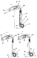
図1は、本発明の一実施例を示す電気掃除機を示す外観斜視図である。   FIG. 1 is an external perspective view showing a vacuum cleaner according to an embodiment of the present invention.

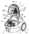
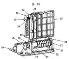
図2は、本発明の一実施例を示す電気掃除機を示す上蓋を開けた状態の斜視図である。   FIG. 2 is a perspective view of the electric vacuum cleaner according to one embodiment of the present invention with the upper lid opened.

図3は、本発明の一実施例を示す掃除機本体の中央縦断面図である。   FIG. 3 is a central longitudinal sectional view of a cleaner body showing an embodiment of the present invention.

まず、図1及び図2を用いて電気掃除機の概要から順に説明する。   First, it demonstrates in order from the outline | summary of a vacuum cleaner using FIG.1 and FIG.2.

図1及び図2に実施例を示すように電気掃除機の掃除機本体ケース1は、後部側に走行用の車輪2を有する。掃除機本体ケース1の前側下部には、走行用キャスター(図示せず)が備わる。   As shown in FIG. 1 and FIG. 2, the vacuum cleaner body case 1 of the electric vacuum cleaner has traveling wheels 2 on the rear side. The lower part of the front side of the cleaner body case 1 is provided with a traveling caster (not shown).

掃除機本体ケース1の前側内部には、集塵室3が設けられる。この集塵室3には、紙,布,不織布を含む集塵袋(紙パック)7若しくはABS材等によるプラスチック製の集塵ケースが取り外し自在に内置される。   A dust collection chamber 3 is provided inside the front side of the cleaner body case 1. In the dust collection chamber 3, a dust collection bag (paper pack) 7 including paper, cloth, and nonwoven fabric, or a plastic dust collection case made of an ABS material or the like is detachably placed.

集塵室3とホース差込口4は掃除機本体ケース1の前側に設けられ、ホース差込口気密部材160を介して、集塵室3に連通する。   The dust collection chamber 3 and the hose insertion port 4 are provided on the front side of the cleaner body case 1 and communicate with the dust collection chamber 3 via the hose insertion port airtight member 160.

集塵室3の上面には、集塵袋(紙パック)若しくは集塵ケースが出し入れされる開口部を上方に有し、この開口部を開閉自在に覆う蓋体5が備わる。蓋体5は掃除機本体ケース1に回動自在に支持され、この開閉自在な前記蓋体5には上部横置除塵体6が保持される。該上部横置除塵体6の支軸81が蓋体5の82に回動自在に取り付けられる。同様に前記上部横置除塵体6に連動して作動するように、上部横置除塵体補助部83の支持軸89が集塵蓋5の支持受部85に回動自在に取り付けられる。また、集塵室3と蓋体5の気密を保持するように気密部材10が取り付けられている。   On the upper surface of the dust collection chamber 3, there is provided a lid body 5 having an opening portion through which a dust collection bag (paper pack) or a dust collection case is put in and out, and covering the opening portion in an openable and closable manner. The lid 5 is rotatably supported by the cleaner body case 1, and the upper horizontal dust removing body 6 is held on the lid 5 that can be freely opened and closed. A support shaft 81 of the upper horizontal dust remover 6 is rotatably attached to 82 of the lid 5. Similarly, the support shaft 89 of the upper horizontal dust removing body auxiliary portion 83 is rotatably attached to the support receiving portion 85 of the dust collecting lid 5 so as to operate in conjunction with the upper horizontal dust removing body 6. An airtight member 10 is attached so as to keep the dust collecting chamber 3 and the lid 5 airtight.

図3に示すように、掃除機本体ケース1の集塵室3には、集塵袋(紙パック)7若しくは集塵ケース(図示せず)が内置される。この集塵袋(紙パック)7は、使い捨ての紙,不織布ないし再利用可能な布集塵袋を含む。又、集塵ケースはABS材やPS材,PET等形状を保持しやすく、ごみを捨てることによって何度も再利用可能なものを含む。   As shown in FIG. 3, a dust collection bag (paper pack) 7 or a dust collection case (not shown) is placed in the dust collection chamber 3 of the cleaner body case 1. The dust bag (paper pack) 7 includes disposable paper, non-woven fabric or reusable cloth dust bag. In addition, the dust collection case includes an ABS material, a PS material, PET, and the like that can easily retain the shape and can be reused many times by throwing away the dust.

掃除機本体ケース1は、集塵室3の後側に後部室を有する。この後部室は、電動送風機8、コードリール9を内置する。   The vacuum cleaner body case 1 has a rear chamber on the rear side of the dust collection chamber 3. This rear chamber houses the electric blower 8 and the cord reel 9.

電動送風機8は、送風部(ファン)と電動機を有する。送風部が前側、電動機が後側になるように置かれる。コードリール9は、電動送風機8の隣に並ぶように置かれる。電動送風機8には、コードリール9を介して電力が供給される。   The electric blower 8 has a blower (fan) and an electric motor. The blower is placed on the front side and the electric motor on the rear side. The cord reel 9 is placed next to the electric blower 8. Electric power is supplied to the electric blower 8 via the cord reel 9.

次に集塵室の気密保持に関して説明する。   Next, airtight maintenance of the dust collection chamber will be described.

図2に示すように集塵室3を覆うように蓋体5が上部ケース130の軸受131に開閉自在に支持され、気密部材10を介して気密を保持するように取り付けられている。   As shown in FIG. 2, the lid 5 is supported by a bearing 131 of the upper case 130 so as to be openable and closable so as to cover the dust collection chamber 3, and is attached through the airtight member 10 so as to maintain airtightness.

図4〜図6を用いて以下説明すると、気密部材10は複数の突起部100と該突起部と一体に形成された緩衝部110とから構成されており、第一の突起部100aは集塵室3の外周部に形成された垂直方向に立ち上がった第一の隔壁103aと第二の隔壁103bによって構成される第一の溝部102aに気密に挿入される。   The airtight member 10 includes a plurality of protrusions 100 and a buffer part 110 formed integrally with the protrusions, and the first protrusion 100a is a dust collecting member. The first partition wall 103a formed by the first partition wall 103a and the second partition wall 103b standing in the vertical direction formed on the outer periphery of the chamber 3 is hermetically inserted.

つまり第一の隔壁103aが形成する溝側側面と第二の隔壁103bが形成する溝側側面に気密部材10の第一の突起部100aがテーパー勘合され、気密部材10の第一の突起部100aを押し込むことによって気密が確保される。   That is, the first protrusion 100a of the airtight member 10 is taper-fitted to the groove side surface formed by the first partition 103a and the groove side surface formed by the second partition 103b, and the first protrusion 100a of the airtight member 10 is tapered. Airtightness is secured by pushing in.

気密部材10は弾性体を用いるのが望ましく、硬度を下げるほど(柔らかくする)気密保持されやすくなる。   It is desirable to use an elastic body for the airtight member 10, and as the hardness is lowered (softened), the airtight member 10 is more easily held.

また第二の突起部100bは第二の隔壁103bと第三の隔壁103cによって構成される第二の溝部102bに挿入され、第一の突起部100aと第二の突起部100bが第二の隔壁103bを挟み込むように合され、これにより、気密部材10と集塵室3の気密は隔壁による溝部102と気密部材10の複数の突起により二重に気密が保持される。 The second protrusion 100b is inserted into the second groove 102b formed by the second partition 103b and the third partition 103c, and the first protrusion 100a and the second protrusion 100b are the second partition. fitted so as to sandwich the 103b, thereby, airtightness of the airtight member 10 and the dust chamber 3 is hermetically double by a plurality of projections of the groove portion 102 and the airtight member 10 by the partition wall is maintained.

第一の突起部100aと第一の溝部102aがテーパー合にて気密を保持しているため、それを更に、第二の隔壁103bを第一の突起部100aと第二の突起部100bで挟み込むことによって、仮に第一の突起部100aと第一の溝部102aのテーパー合による気密もれが発生した場合でも、第二の隔壁103bを第一の突起部100aと第二の突起部100bで気密に挟みこんでいるので、二重のシール効果が得られる。 Since the first protrusion 100a and the first groove portion 102a is holding the airtightness at taper fitting, it further a second partition wall 103b at the first projecting portion 100a and the second protruding portion 100b by sandwiching, if the first protruding portions 100a and even when the air leakage due to the tapered fitting of the first trench 102a is generated, the second partition wall 103b and the first projection portion 100a second protrusion 100b Since it is sandwiched in an airtight manner, a double sealing effect can be obtained.

また、第二の隔壁103bと第三の隔壁103cによって形成される第二の溝部102bへ第二の突起部100bをテーパー合にて気密を保持することにより、更に高い気密保持効果が得られる。 Further, by maintaining a hermetic seal at the second partition wall 103b and the second protrusion 100b taper fitting the coupling to the second trench 102b that is formed by the third partition wall 103c, obtained higher airtightness retaining effect .

更に、隔壁の数を第4,第5と増やし、隔壁間に構成される溝部の数を増やし、それに伴い、気密部材10の形成する複数の突起部100の数を増やし、上述したような合関係の構成を増やすことにより、更に集塵室3と気密部材10の気密性を向上させることができる。 Further, the number of partition walls is increased to the fourth and fifth, the number of grooves formed between the partition walls is increased, and accordingly, the number of the plurality of protrusions 100 formed by the airtight member 10 is increased, and the above-described fitting is performed. By increasing the configuration of the joint relationship, the airtightness of the dust collection chamber 3 and the airtight member 10 can be further improved.

また、気密部材10の複数の突起部100と一体に緩衝部110が形成され、集塵室3の最も外側に位置する隔壁(本図中では第三の隔壁103c)を覆うように配置され、外部からの衝撃に対して本体を保護し、また家庭の家具や建物を保護する役割を果たしている。   Further, a buffer portion 110 is formed integrally with the plurality of protrusions 100 of the airtight member 10, and is disposed so as to cover the partition wall (the third partition wall 103c in the figure) located on the outermost side of the dust collection chamber 3, It protects the main body against external impacts and protects home furniture and buildings.

さらに、緩衝部110の他端106は集塵室3の隔壁により構成される溝部102と気密部材10のテーパー合により気密を保持している部分を、別部品を用いることなく確実に固定するために、集塵室3の外周部に垂直方向に係止突起107を設け、これと係合させるために気密部材10に係合突起106を設けている。 Furthermore, a portion other end 106 of the buffer 110 which holds the airtight by taper fitting groove portion 102 and the airtight member 10 composed of the dust collecting chamber 3 of the partition wall, reliably fixed without using a separate component For this purpose, a locking projection 107 is provided in the vertical direction on the outer peripheral portion of the dust collecting chamber 3, and an engagement projection 106 is provided on the airtight member 10 in order to engage with this.

係止突起107は集塵室3の外周に沿って連続的な隔壁を構成する場合と断続的な突起を均等若しくは不均一に配置させることにより、気密部材10を確実に固定する。   The locking projection 107 securely fixes the airtight member 10 by forming a continuous partition along the outer periphery of the dust collecting chamber 3 and disposing the intermittent projections uniformly or non-uniformly.

係止突起107は連続的に形成される隔壁と集塵室3に対して断続的に垂直方向に形成される隔壁とを合せる事により、更に気密部材10の係合性を高めることができる。   The engagement protrusion 107 can further enhance the engagement of the airtight member 10 by combining the partition wall formed continuously with the partition wall formed in the vertical direction intermittently with respect to the dust collection chamber 3.

また、気密部材10の係合突起106は緩衝部110の端面に形成され、気密部材10の複数の突起部100に略対向するように形成され、連続的若しくは不連続に係合突起106が形成され、隔壁103から気密部材10が外部からの衝撃及び使用者の偶発的操作から緩衝部110が剥離するのを防止し、気密を保持する。   Further, the engagement protrusions 106 of the airtight member 10 are formed on the end face of the buffer part 110 and are formed so as to be substantially opposed to the plurality of protrusions 100 of the airtight member 10, and the engagement protrusions 106 are formed continuously or discontinuously. In addition, the airtight member 10 is prevented from peeling from the partition wall 103 due to external impact and user's accidental operation, and the airtightness is maintained.

集塵室3の最も外側に位置する隔壁(本図中では第三の隔壁103c)は内側に第二の突起部100bを合させ、係止突起107と係合突起106を合させた際に、緩衝部110及び気密部材10自体が集塵室3から外れて気密漏れを生じるのを、かぎ型構造を形成し防止している。 The partition wall (the third partition wall 103c in the figure) located on the outermost side of the dust collecting chamber 3 has the second protrusion 100b fitted inside and the locking protrusion 107 and the engagement protrusion 106 fitted . At this time, the buffer part 110 and the airtight member 10 themselves are separated from the dust collecting chamber 3 to cause airtight leakage by forming a hook structure.

本体運転中は、集塵室3内部が負圧になるので蓋体5の気密リブ108が気密部材を押し付ける方向に働き、集塵室3と蓋体5を気密に保つことができる。   During the operation of the main body, the inside of the dust collection chamber 3 becomes negative pressure, so that the airtight rib 108 of the lid 5 works in the direction of pressing the airtight member, and the dust collection chamber 3 and the lid 5 can be kept airtight.

また、運転中は気密部材10の複数の突起部100は溝部102により押し付けられる方向に働き気密が取れるのと同時に、外れも防止することができる。   Further, during operation, the plurality of protrusions 100 of the airtight member 10 work in the direction in which they are pressed by the grooves 102, and can be prevented from coming off at the same time as airtightness can be taken.

集塵室3内の気密を取りやすくするために、気密部材10の蓋体5の気密リブ108と接する部分をリップ形状105とすることで集塵室3が負圧となった時により気密がとれる。   In order to facilitate airtightness in the dust collection chamber 3, the portion of the lid 5 of the airtight member 10 that is in contact with the airtight rib 108 is formed into a lip shape 105, so that the airtightness is further increased when the dust collection chamber 3 becomes negative. I can take it.

気密部材の材質をより柔らかい弾性部材とすることで、更に気密が取れやすくなる。   By making the material of the airtight member a softer elastic member, it becomes easier to take airtightness.

前述の前提条件として、蓋体5の気密リブ108と気密部材10のリップ形状105は均一に干渉または接している必要がある。   As the above-mentioned precondition, the airtight rib 108 of the lid 5 and the lip shape 105 of the airtight member 10 need to interfere or contact uniformly.

リップ形状105の端面は蓋体5の外周端面109の肉厚より内側であることが望ましい。   It is desirable that the end face of the lip shape 105 is inside the thickness of the outer peripheral end face 109 of the lid 5.

蓋体5の外周端面109の肉厚より内側であれば外観的にも美しく、また本体運転時に、集塵室3が負圧になることよる、蓋体5の集塵室側への沈み込みによって、リップ形状105が蓋体5の気密リブ108によって押される際に、蓋体5の外周端面109よりもリップ形状105の端面が出ている場合、美観を損ねるばかりではなく、集塵室3内の気密を取るための気密リブ108が気密部材10のリップ形状105を押し付けて気密をとる前に、蓋体5の外周端面109がリップ形状105を押してしまい、その部分から気密が漏れてしまう可能性がある。   If it is inside the thickness of the outer peripheral end surface 109 of the lid 5, the appearance is also beautiful, and the sink 5 sinks into the dust collection chamber due to negative pressure in the dust collection chamber 3 during operation of the main body. Thus, when the lip shape 105 is pushed by the airtight rib 108 of the lid 5, if the end face of the lip shape 105 protrudes from the outer peripheral end face 109 of the lid 5, not only the appearance is impaired, but also the dust collecting chamber 3 Before the airtight rib 108 for taking the airtightness presses the lip shape 105 of the airtight member 10 to achieve the airtightness, the outer peripheral end surface 109 of the lid 5 pushes the lip shape 105, and the airtightness leaks from that portion. there is a possibility.

このため、リップ形状105の端面を蓋体5の外周端面109の肉厚よりも内側に形成するか若しくは、蓋体5の気密リブ108と外周端面109の縁面距離を十分に取って、外周端面109にリップ形状105が押されない位置に構成する必要がある。   For this reason, the end surface of the lip shape 105 is formed on the inner side of the thickness of the outer peripheral end surface 109 of the lid body 5 or the edge distance between the airtight rib 108 and the outer peripheral end surface 109 of the lid body 5 is sufficiently taken to It is necessary to configure the lip shape 105 at a position where the end surface 109 is not pushed.

次に集塵袋7(紙パック)又は集塵ケース(図示せず)の着脱に関して説明する。   Next, the attachment / detachment of the dust bag 7 (paper pack) or dust collection case (not shown) will be described.

集塵室3に内置した集塵袋(紙パック)7及び集塵ケース(図示せず)の取り出し性を考慮し、特に集塵ケースタイプの場合には、頻繁にごみすて作業をする可能性があるので、気密部材10の内側面111が集塵室3の第一の隔壁103aの内側面112と同一面若しくは、それよりも外側に位置させることによって、摩擦抵抗の大きい気密部材10(弾性部材)に直接集塵袋(紙パック)7若しくは集塵ケース(図示せず)を触れさせること無く、また、気密部材10の内側への出ばりによって内側へ押さえつけられることなく着脱作業をすることができるので、軽い力での集塵袋(紙パック)7及び集塵ケース(図示せず)の着脱が可能となり、ごみを捨てやすくすることができる。   Considering the take-out property of the dust bag (paper pack) 7 and dust case (not shown) placed in the dust chamber 3, especially in the case of the dust case, the possibility of frequent trashing work Therefore, when the inner side surface 111 of the airtight member 10 is located on the same surface as the inner side surface 112 of the first partition wall 103a of the dust collecting chamber 3 or on the outer side, the airtight member 10 (elasticity) having a large frictional resistance is provided. Do not attach the dust collecting bag (paper pack) 7 or the dust collecting case (not shown) directly to the member, and do not press the inside of the airtight member 10 without being pressed inside. Therefore, it is possible to attach and detach the dust collection bag (paper pack) 7 and the dust collection case (not shown) with a light force, and it is possible to make it easy to throw away garbage.

次に除塵関連に関して説明する。   Next, the dust removal related will be described.

集塵袋7の除塵は、除塵手段で行われる。除塵手段は、図11に示すように除塵部材150とコードリール9に駆動され、かつ前記除塵部材150に振動動作を起こさせる除塵回転体12と動力分岐機構25を有する。   Dust removal of the dust bag 7 is performed by dust removing means. As shown in FIG. 11, the dust removing means includes a dust removing rotating body 12 and a power branch mechanism 25 that are driven by the dust removing member 150 and the cord reel 9 and cause the dust removing member 150 to vibrate.

除塵部材150は集塵室3に備えられ、集塵室3に置かれる集塵袋7は、除塵部材150で、振動させられて内部に付着する塵埃が振るい落とされる。   The dust removal member 150 is provided in the dust collection chamber 3, and the dust collection bag 7 placed in the dust collection chamber 3 is vibrated by the dust removal member 150, and dust attached to the inside is shaken off.

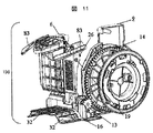
除塵駆動伝達ユニット11(図7)は、掃除機本体ケース1の内底部に備えられる。除塵駆動伝達ユニット11は、除塵回転体12と、伝達歯車13を有する。図11に示すように、この伝達歯車13は、コードリール9の駆動歯車14に噛み合う。   The dust removal drive transmission unit 11 (FIG. 7) is provided on the inner bottom of the cleaner body case 1. The dust removal drive transmission unit 11 includes a dust removal rotary body 12 and a transmission gear 13. As shown in FIG. 11, the transmission gear 13 meshes with the drive gear 14 of the cord reel 9.

動力分岐機構25は集塵室3内部に備わり、前記除塵回転体12の回転力を利用し前記上部横置除塵体6へと動力を伝え、前記上部横置除塵体補助部83が連動する。この動力分岐機構25の詳細については後述する。   The power branch mechanism 25 is provided inside the dust collecting chamber 3, transmits power to the upper horizontal dust removing body 6 using the rotational force of the dust removing rotary body 12, and the upper horizontal dust removing body auxiliary unit 83 is interlocked. Details of the power branch mechanism 25 will be described later.

コードリール9の回転で、駆動歯車14,伝達歯車13を介して除塵駆動伝達ユニット11の除塵回転体12に回転が伝わる。除塵回転体12の回転により、除塵部材150は振動させられ、集塵袋7内の除塵が行われる。   The rotation of the cord reel 9 is transmitted to the dust removal rotating body 12 of the dust removal drive transmission unit 11 through the drive gear 14 and the transmission gear 13. The dust removal member 150 is vibrated by the rotation of the dust removal rotating body 12, and dust removal in the dust collection bag 7 is performed.

除塵部材について、図8〜図12を引用して更に詳しく述べる。   The dust removing member will be described in more detail with reference to FIGS.

除塵部材150は、縦置除塵体15と、下部横置除塵体16と、上部横置除塵体6と、上部横置除塵体補助部83を有する。縦置除塵体15の下端と、下部横置除塵体16の後端は支軸17により回動自在に結合されている。縦置除塵体15と下部横置除塵体16は、折り畳まれた0度(図12bに示す状態に近い)から開かれた約90(図12aに示す状態)の範囲で回動する。   The dust removing member 150 includes a vertical dust remover 15, a lower horizontal dust remover 16, an upper horizontal dust remover 6, and an upper horizontal dust remover auxiliary unit 83. The lower end of the vertical dust remover 15 and the rear end of the lower horizontal dust remover 16 are coupled to each other by a support shaft 17 so as to be rotatable. The vertical dust remover 15 and the lower horizontal dust remover 16 rotate in the range of about 90 (state shown in FIG. 12a) opened from the folded 0 degree (close to the state shown in FIG. 12b).

縦置除塵体15は、下端にストッパー18を有する。下部横置除塵体16が90度まで開いたところで、下部横置除塵体16はストッパー18で抑えられ、それ以上は開かない。   The vertical dust remover 15 has a stopper 18 at the lower end. When the lower horizontal dust remover 16 is opened to 90 degrees, the lower horizontal dust remover 16 is held by the stopper 18 and cannot be opened any further.

なお、最大開き角度は、下部横置除塵体16が集塵室3の内底部に接触しなければ、90度以下でも90度以上でもよい。   The maximum opening angle may be 90 degrees or less or 90 degrees or more as long as the lower horizontal dust remover 16 does not contact the inner bottom of the dust collection chamber 3.

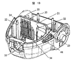
縦置除塵体15は、上側両端に支持軸突起19が設けられる除塵枠体部20を有する。掃除機本体ケース1は、図3,図13に示すように、集塵室3と後部室を仕切る中間仕切壁21を有する。この中間仕切壁21は、集塵室3側に縦に走る二つの支持リブ22が間隔を隔て設けられ、支持リブ22は、図13に示すように、上側に支持孔23を有し、前記中間仕切壁21には動力分岐機構25を取り付けるための係止溝44を有する。   The vertical dust removing body 15 has a dust removing frame body portion 20 provided with support shaft protrusions 19 at both upper ends. As shown in FIGS. 3 and 13, the cleaner body case 1 has an intermediate partition wall 21 that partitions the dust collection chamber 3 and the rear chamber. The intermediate partition wall 21 is provided with two support ribs 22 running vertically on the dust collection chamber 3 side, with the support ribs 22 having support holes 23 on the upper side as shown in FIG. The intermediate partition wall 21 has a locking groove 44 for attaching the power branch mechanism 25.

支持リブ22の支持孔23に縦置除塵体15の支持軸突起19は回動自在に嵌る。これにより、前記縦置除塵体15と前記下部横置除塵体16は、集塵室3に揺振自在に置かれる。   The support shaft protrusion 19 of the vertical dust remover 15 is rotatably fitted in the support hole 23 of the support rib 22. Thus, the vertical dust remover 15 and the lower horizontal dust remover 16 are placed in the dust collecting chamber 3 so as to be freely swingable.

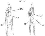
支持リブ22は、図14aに示すように、対向面(内側面)に支持孔23の上側から支持リブ22に向けて形成された傾斜溝24aを有する。この傾斜溝24aは、上側に向かって外向きに傾く。支持軸突起19aも端側が傾斜面を有する。このため、支持軸突起19aを傾斜溝24aに沿って上から下に滑らせることにより、支持軸突起19aは支持孔23に容易に嵌る。前記縦置除塵体15,前記下部横置除塵体16との取り付けが容易に行われる。   As shown in FIG. 14 a, the support rib 22 has an inclined groove 24 a formed on the facing surface (inner side surface) from the upper side of the support hole 23 toward the support rib 22. The inclined groove 24a is inclined outward toward the upper side. The support shaft protrusion 19a also has an inclined surface on the end side. For this reason, the support shaft protrusion 19a is easily fitted into the support hole 23 by sliding the support shaft protrusion 19a from the top to the bottom along the inclined groove 24a. The vertical dust remover 15 and the lower horizontal dust remover 16 are easily attached.

また、支持リブ22は場合によって、図14bに示すように、対向面(内側面)の少なくとも1つが支持孔23の前側(ホース差込口4側)から支持リブ22に向けて形成された傾斜溝24bを有する。この傾斜溝24bは、前側に向かって外向きに傾く。この際、支持軸突起19は支持軸突起19bの形状にすることで前側から中間仕切壁21に垂直に向かって傾斜溝24b上を滑らせることで、支持突起19bは支持孔23に容易に嵌る。   Further, in some cases, the support rib 22 is inclined such that at least one of the opposing surfaces (inner side surfaces) is formed from the front side (the hose insertion port 4 side) of the support hole 23 toward the support rib 22 as shown in FIG. 14b. A groove 24b is provided. The inclined groove 24b is inclined outward toward the front side. At this time, the support protrusion 19 is easily fitted into the support hole 23 by sliding the support shaft protrusion 19 on the inclined groove 24b perpendicularly to the intermediate partition wall 21 from the front side by forming the shape of the support shaft protrusion 19b. .

動力分岐機構25について説明する。   The power branch mechanism 25 will be described.

動力分岐機構25は集塵室内にあり、前記縦置除塵体15と、前記中間仕切壁21の間に配置され、該中間仕切壁21に設けた係止溝44に取り付けられる。   The power branch mechanism 25 is in a dust collection chamber, is disposed between the vertical dust remover 15 and the intermediate partition wall 21, and is attached to a locking groove 44 provided in the intermediate partition wall 21.

前記動力分岐機構25は、前記除塵駆動伝達ユニット11の除塵回転体12の突起27と、動力分岐機構25のカムクランク突起28とが係合し、除塵回転体12の回転運動に連動して係合部がこの場合は下へと引かれ該動力分岐機構25の付勢バネ29にて元に戻されることで往復運動を行い、該動力分岐機構25のカムクランク30によって、除塵回転体12の回転運動の駆動力をこの場合は上方向へ変換し上部横置除塵体6へ動力を伝達し、上部横置除塵体補助部83まで動力が伝達される。   The power branch mechanism 25 is engaged with the protrusion 27 of the dust removal rotary body 12 of the dust removal drive transmission unit 11 and the cam crank protrusion 28 of the power branch mechanism 25 and interlocks with the rotational movement of the dust removal rotary body 12. In this case, the joint portion is pulled downward and returned to its original position by the urging spring 29 of the power branch mechanism 25 to perform reciprocating motion. The cam crank 30 of the power branch mechanism 25 causes the dust removal rotating body 12 to move back and forth. In this case, the driving force of the rotary motion is converted upward and the power is transmitted to the upper horizontal dust removing body 6, and the power is transmitted to the upper horizontal dust removing body auxiliary unit 83.

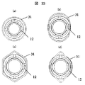
除塵回転体12は、外周に巻装される除塵バネ31を有する。除塵バネ31は、除塵回転体12の長手方向に沿って螺旋状に巻かれ、図33aからdに示すように長手方向の断面は略円形若しくは、略長円若しくは、多角形ないし外周に突き出る複数の凹凸形状を有する。除塵部材150の縦置除塵体15に備える付勢バネ26は、縦置除塵体15を中間仕切壁21方向へ押し付ける。   The dust removal rotary body 12 has a dust removal spring 31 wound around the outer periphery. The dust removal spring 31 is spirally wound along the longitudinal direction of the dust removal rotary body 12, and as shown in FIGS. 33a to 33d, the longitudinal section has a substantially circular shape, a substantially oval shape, a polygonal shape, or a plurality of protrusions protruding to the outer circumference. It has an uneven shape. The biasing spring 26 provided in the vertical dust removing body 15 of the dust removing member 150 presses the vertical dust removing body 15 toward the intermediate partition wall 21.

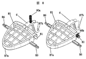
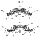
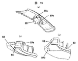
上部横置除塵体及び上部横置除塵体補助部について説明する。   The upper horizontal dust remover and the upper horizontal dust remover auxiliary unit will be described.

前記除塵駆動伝達ユニット11の前記除塵回転体12から前記動力分岐機構25のカムクランク30を介して前記上部横置除塵体6の端部87bが上方向の荷重を受けて前記上部横置除塵体補助部83が略上下方向に作動する。   The upper lateral dust removing body receives an upward load from the dust removing rotary body 12 of the dust removing drive transmission unit 11 through the cam crank 30 of the power branch mechanism 25 so that the end portion 87b of the upper horizontal dust removing body 6 receives an upward load. The auxiliary part 83 operates substantially in the vertical direction.

前記横置除塵体6は略上下方向に作動した際に、前記上部横置除塵体6の荷重側以外の端部(上部横置除塵体伝達軸)86を有し、前記上部横置除塵体6の作動を前記上部横置除塵体補助部83へ伝達される。   The horizontal dust remover 6 has an end (upper horizontal dust remover transmission shaft) 86 other than the load side of the upper horizontal dust remover 6 when operated in a substantially vertical direction, and the upper horizontal dust remover 6 6 is transmitted to the upper horizontal dust removing body auxiliary portion 83.

前記上部横置除塵体伝達軸86の作動は、前記上部横置除塵体補助部83の作動受部88から作動を伝達し、前記上部横置除塵体補助部83を略上下方向に作動させる。   The operation of the upper horizontal dust removing body transmission shaft 86 transmits the operation from the operation receiving portion 88 of the upper horizontal dust removing body auxiliary portion 83, and operates the upper horizontal dust removing body auxiliary portion 83 in a substantially vertical direction.

前記上部横置除塵体補助部の作動受部88は前記上部横置除塵体補助部の支持軸89aに対して前記上部横置除塵体6側に配置する。   The operation receiving portion 88 of the upper horizontal dust removing body auxiliary portion is disposed on the upper horizontal dust removing body 6 side with respect to the support shaft 89a of the upper horizontal dust removing body auxiliary portion.

これによって、前記上部横置除塵体6が前記動力分岐機構25から上方向への作動を受け、前記上部横置除塵体6の前端87aが押し下げられ、集塵袋7の上面を瞬時に叩くと同時に、連動してる前記上部横置除塵体補助部83は図17bのように支持軸89aを基準に全体を上方向に持ち上げ、集塵袋7への加振に対してためを持たせる。   As a result, the upper horizontal dust remover 6 is actuated upward from the power branch mechanism 25, the front end 87a of the upper horizontal dust remover 6 is pushed down, and the upper surface of the dust bag 7 is instantly hit. At the same time, the upper horizontal dust removing body auxiliary portion 83 which is interlocked lifts the whole upward with reference to the support shaft 89a as shown in FIG.

次にバネ90a,90b等による付勢により、前記上部横置除塵部6が元の位置にもどる際に、前記支持軸89aを基準に全体を上方向に持ち上げていた前記上部横置除塵体補助部83が、図17aのように自重と前記上部横置除塵体伝達軸86から、前記作動受部88が動力を受けることによって、集塵袋7の上面を叩くことが出来る。   Next, when the upper horizontal dust removing portion 6 returns to its original position by the biasing by the springs 90a, 90b, etc., the upper horizontal dust removing body auxiliary that has been lifted upwards with respect to the support shaft 89a as a reference. The part 83 can hit the upper surface of the dust bag 7 when the operation receiving part 88 receives power from its own weight and the upper lateral dust removing body transmission shaft 86 as shown in FIG. 17a.

この一連の動作によって、前記動力分岐機構25からの1回の動力伝達によって、集塵袋7の上面を交互に最低2回及び2ヶ所以上について加振して除塵をすることが可能となる。   By this series of operations, it is possible to perform dust removal by vibrating the upper surface of the dust bag 7 alternately at least twice and at two or more locations by one power transmission from the power branch mechanism 25.

また、場合によっては前記上部横置除塵体補助部83の作動受部88を支持軸89bに対して、前記上部横置除塵体6から離れた側に配置することによって、前記動力分岐機構25からの1回の動力伝達によって、集塵袋7の上面の1ヶ所またはそれ以上の箇所を同時に加振することができる。   Further, in some cases, the operation receiving portion 88 of the upper horizontal dust removing body auxiliary portion 83 is disposed on the side away from the upper horizontal dust removing body 6 with respect to the support shaft 89b. By one-time power transmission, one place or more places on the upper surface of the dust bag 7 can be vibrated simultaneously.

集塵袋7は、図3に示すように、後側が除塵部材150の縦置除塵体15に、下側が下部横置除塵体16に、上側が上部横置除塵体6及び上部横置除塵体補助部83に当接する。除塵回転体12が回転することにより、縦置除塵体15と回動自在に結合されている下部横置除塵体16は、付勢バネ26に抗して、前記縦置除塵体15は前後方向に、又下部横置除塵体16は前記縦置除塵体15と連動し、前後に振動すると共に略上下にも振動する。また、前記動力分岐機構25は除塵回転体12の突起部27からの動力を伝達しカムクランク30を介して上部横置除塵体6及び上部横置除塵体補助部83を略上下に振動させる。   As shown in FIG. 3, the dust bag 7 has a rear side in the vertical dust remover 15 of the dust removing member 150, a lower side in the lower horizontal dust remover 16, and an upper side in the upper horizontal dust remover 6 and the upper horizontal dust remover. It contacts the auxiliary part 83. By rotating the dust removal rotating body 12, the lower horizontal dust removal body 16 rotatably coupled to the vertical dust removal body 15 is opposed to the biasing spring 26, and the vertical dust removal body 15 is moved in the front-rear direction. In addition, the lower horizontal dust removing body 16 is interlocked with the vertical dust removing body 15 so as to vibrate back and forth and also vibrate substantially vertically. Further, the power branch mechanism 25 transmits power from the protrusion 27 of the dust removing rotary body 12 and vibrates the upper horizontal dust removing body 6 and the upper horizontal dust removing body auxiliary portion 83 substantially vertically through the cam crank 30.

集塵袋7の後側は、縦置除塵体15により前後に揺すられ、下側は下部横置除塵体16で前後に擦られるとともに上下に多少振られ、上側は上部横置除塵体6及び上部横置除塵体補助部83にて上下に振られる。この振動により、集塵袋7内に付着する塵埃が除塵され、集塵袋7の通気性が回復し、更なる吸塵ができる。特に、集塵性能への影響が大きい上側は、上部横置除塵体及び上部横置除塵体補助部によって大きな効果が得られる。これを繰り返すことにより、集塵袋7内が一杯になるまで吸塵できる。   The rear side of the dust bag 7 is swung back and forth by the vertical dust remover 15, the lower side is rubbed back and forth by the lower horizontal dust remover 16 and slightly shaken up and down, and the upper side is the upper horizontal dust remover 6 and It is shaken up and down by the upper horizontal dust removing body auxiliary unit 83. Due to this vibration, dust adhering in the dust bag 7 is removed, the air permeability of the dust bag 7 is restored, and further dust absorption can be performed. In particular, on the upper side having a large influence on the dust collection performance, a large effect can be obtained by the upper horizontal dust remover and the upper horizontal dust remover auxiliary unit. By repeating this, dust can be absorbed until the inside of the dust bag 7 is filled.

集塵室内の掃除について説明する。   The cleaning of the dust collection chamber will be described.

塵埃は、集塵袋7内に集塵される。しかし、集塵袋7を取り外す際、集塵袋7内に溜まった塵埃が誤って集塵室3の下部にこぼれる場合がある。この時、集塵室蓋5を開いて、集塵室3から集塵袋7を外し、内底部に溜まった細塵の掃除をする。   Dust is collected in the dust bag 7. However, when removing the dust bag 7, dust accumulated in the dust bag 7 may accidentally spill into the lower part of the dust chamber 3. At this time, the dust collection chamber lid 5 is opened, the dust collection bag 7 is removed from the dust collection chamber 3, and the fine dust accumulated in the inner bottom is cleaned.

この際に、除塵部材150の下部横置除塵体16を図12に示すように折り畳むことにより、内底部側から下部横置除塵体16が一時的に除かれた状態になる。このため内底部が容易に、しかも細塵を残さず掃除できる。   At this time, by folding the lower horizontal dust removing body 16 of the dust removing member 150 as shown in FIG. 12, the lower horizontal dust removing body 16 is temporarily removed from the inner bottom side. For this reason, the inner bottom can be easily cleaned without leaving fine dust.

下部横置除塵体16は、図13に示すように、前後方向に延在する複数のスリット32が並ぶように設けられている。集塵袋7を抜けた気流は、スリット32を通って電動送風機8へと流れる。下部横置除塵体16のスリット32は、気流の流れを良くするためである。   As shown in FIG. 13, the lower horizontal dust remover 16 is provided so that a plurality of slits 32 extending in the front-rear direction are arranged. The airflow that has passed through the dust bag 7 flows through the slit 32 to the electric blower 8. The slit 32 of the lower horizontal dust remover 16 is for improving the flow of airflow.

スリット32には、集塵室3の内底部に一体に設けられた案内リブ33が摺動自在に嵌る。この案内リブ33は、除塵動作の前後方向振動ではガイドとして機能する。前後方向振動と交差する方向の動きは案内リブ33により規制される。   A guide rib 33 provided integrally with the inner bottom of the dust collecting chamber 3 is slidably fitted into the slit 32. The guide rib 33 functions as a guide in the longitudinal vibration of the dust removal operation. The movement in the direction intersecting with the longitudinal vibration is regulated by the guide rib 33.

このため、電気掃除機本体の置かれる姿勢が横倒しになっていても案内リブ33の案内により、除塵部材150の除塵動作は作動不良を起こすことなく、円滑に行われる。   For this reason, even if the electric vacuum cleaner main body is placed on its side, the dust removal operation of the dust removing member 150 is smoothly performed without causing malfunction due to the guidance of the guide rib 33.

また、除塵部材150は下部横置除塵体16をストッパー18で支えているので、除塵動作で下部横置除塵体16と集塵室3の内底部は擦れ合うことなく、円滑な除塵動作が行われる。   Further, since the dust removing member 150 supports the lower horizontal dust remover 16 with the stopper 18, the dust removal operation allows a smooth dust removal operation without rubbing between the lower horizontal dust remover 16 and the inner bottom of the dust collecting chamber 3. .

除塵駆動伝達ユニット11の除塵バネ31は、縦置除塵体15の下端に当接する。この当接部は、縦置除塵体15の下端後部で支軸17の近傍に位置し、円弧形状を有する。この円弧面は、縦置除塵体15の幅範囲内に亘り形成されている。   The dust removal spring 31 of the dust removal drive transmission unit 11 contacts the lower end of the vertical dust remover 15. This abutting portion is located in the vicinity of the support shaft 17 at the lower end rear portion of the vertical dust remover 15 and has an arc shape. This arc surface is formed over the width range of the vertical dust remover 15.

この円弧面の当接部に当接する除塵バネ31は図33aからdに示すように長手方向の断面は略円形若しくは、略長円若しくは多角形ないし外周に突き出る複数の凹凸形状が当接しても、円弧面により除塵回転体12の円滑な回転が維持される。これにより、除塵部材150の振動作動が良好に行われ、集塵袋7の除塵が効率良く行われる。   As shown in FIGS. 33a to 33d, the dust removing spring 31 that contacts the contact portion of the arcuate surface is substantially circular in cross section in the longitudinal direction, or is substantially oval, polygonal, or a plurality of uneven shapes protruding on the outer periphery. The smooth rotation of the dust removal rotary body 12 is maintained by the arc surface. Thereby, the vibration operation of the dust removal member 150 is performed satisfactorily, and the dust collection bag 7 is efficiently removed.

図13,図20に示すように、除塵部材150の下部横置除塵体16は、前後に通じる方向から見て中央が隆起する形状を有する。このような形状に有するので、平板状のものに比べ、構造上の強度が高まり、前記集塵室3に添った形状となり、スペースを有効活用することができる。   As shown in FIGS. 13 and 20, the lower horizontal dust removal body 16 of the dust removal member 150 has a shape in which the center rises when viewed from the front-rear direction. Since it has such a shape, the structural strength is higher than that of a flat plate, and the shape conforms to the dust collecting chamber 3, so that the space can be used effectively.

下部横置除塵体16は、縦置除塵体15の下端後部に支軸17で片持ち支持され、かつスリット32が形成された薄手のものである。中央が隆起する強い構造であるので、折れ曲がることなく、集塵袋7を下から支えることができる。このため、下部横置除塵体16が集塵室3の内底部に接触することも生じることなく、除塵の振動動作が良好に行われる。   The lower horizontal dust remover 16 is a thin one that is cantilevered by a support shaft 17 on the rear lower end of the vertical dust remover 15 and has a slit 32 formed therein. Since the center is a strong structure, the dust bag 7 can be supported from below without being bent. For this reason, the lower horizontal dust removing body 16 does not come into contact with the inner bottom portion of the dust collecting chamber 3, and the dust removing vibration operation is favorably performed.

図13に示すように、集塵室3と後部室を仕切る中間仕切壁21は、内部流通口34を有する。内部流通口34は、電動送風機8の送風部(ファン)の吸込口に対向するように中央から片側に偏在させて設ける。   As shown in FIG. 13, the intermediate partition wall 21 that partitions the dust collection chamber 3 and the rear chamber has an internal circulation port 34. The internal circulation port 34 is provided so as to be unevenly distributed from the center to one side so as to face the suction port of the air blower (fan) of the electric blower 8.

集塵室3に流入する気流は、内部流通口34を通って電動送風機8に流れる。内部流通口34には、複数の縦格子リブ35が設けられる。   The airflow flowing into the dust collection chamber 3 flows to the electric blower 8 through the internal circulation port 34. The internal circulation port 34 is provided with a plurality of vertical lattice ribs 35.

図2に示すように、集塵室3に内置されると除塵部材150は、縦置除塵体15が内部流通口34のところに対向するように置かれる。縦置除塵体15の幅は、集塵室3の横幅(中間仕切壁21の横幅)より狭い。このため、コードリール9側に対応する中間仕切壁21のところには、縦置除塵体15は存在しない。   As shown in FIG. 2, when placed in the dust collection chamber 3, the dust removing member 150 is placed such that the vertical dust removing body 15 faces the internal circulation port 34. The width of the vertical dust remover 15 is narrower than the width of the dust collection chamber 3 (the width of the intermediate partition wall 21). For this reason, the vertical dust remover 15 does not exist at the intermediate partition wall 21 corresponding to the cord reel 9 side.

下部横置除塵体16は、縦置除塵体15の横幅より広い横幅を有し、集塵室3の内底部の横幅範囲に広がる。   The lower horizontal dust remover 16 has a wider width than that of the vertical dust remover 15, and extends in the width range of the inner bottom portion of the dust collection chamber 3.

集塵袋7内に吸い込まれた塵埃は、集塵袋7の後部側で内部流通口34に近いところの内側に多く付着する。この多く付着するところを積極的に除塵振動させるために縦置除塵体15の横幅を集塵室3の横幅よりも狭くした。   A large amount of dust sucked into the dust bag 7 adheres to the inside of the dust bag 7 near the internal circulation port 34 on the rear side. The horizontal width of the vertical dust remover 15 was made narrower than the horizontal width of the dust collection chamber 3 in order to positively vibrate and remove dust where these many deposits occur.

集塵袋7の底側は、塵埃付着の偏りは少ないので、除塵振動が出来るだけ広い範囲に
及ぶように下部横置除塵体16の横幅を縦置除塵体15よりも広くした。
On the bottom side of the dust collection bag 7, there is little bias of dust adhesion, so the horizontal width of the lower horizontal dust remover 16 is made wider than that of the vertical dust remover 15 so that the dust removal vibration is as wide as possible.

なお、縦置除塵体15と下部横置除塵体16の横幅を同じにすることも可能である。   The horizontal width of the vertical dust remover 15 and the lower horizontal dust remover 16 can be the same.

集塵袋7の天面は、特に巻き上げられた粉塵を含む微細塵が多く、集塵袋7の天面側の略中央に上部横置除塵体6を配置し除塵することにより、天面全体に振動が行き渡る。   The top surface of the dust bag 7 has a lot of fine dust, especially dust that has been rolled up, and the top horizontal dust remover 6 is disposed at the approximate center of the top surface side of the dust bag 7 to remove the dust. Vibration spreads through.

図16,図22を引用して付勢バネ26の取り付け方法について説明する。   A method of attaching the biasing spring 26 will be described with reference to FIGS.

縦置除塵体15の除塵枠体部20は、一方の側面上部にバネ収容部36を有する。   The dust-removing frame body portion 20 of the vertical dust-removing body 15 has a spring accommodating portion 36 on one side surface upper portion.

バネ収容部36は、除塵枠体部20の外側面と、前側壁37と、内側壁38で形成される。バネ収容部36の後側は壁部がなく、開放になっている。前述した一方の支持軸突起19は、外側壁38の外側に設けられている。   The spring accommodating portion 36 is formed by the outer side surface of the dust removing frame body portion 20, the front side wall 37, and the inner side wall 38. The rear side of the spring accommodating portion 36 has no wall portion and is open. One of the support shaft protrusions 19 described above is provided outside the outer wall 38.

バネ収容部36内には、除塵枠体部20の外側面に付勢バネ26の中心を支持するバネ支持軸突起39と、付勢バネ26の左右のガタ及び倒れを防止するための補強リブ40を有する。   In the spring accommodating portion 36, a spring support shaft projection 39 that supports the center of the urging spring 26 on the outer surface of the dust removing frame body portion 20, and left and right backlash of the urging spring 26 and a reinforcing rib for preventing falling 40.

付勢バネ26は、図22に示すように、バネ収容部36内に収納され、付勢バネ端部41を中間仕切壁21に押圧する。これにより、縦除塵体15は付勢バネ26の力で支持軸突起19を支点としてP矢印方向の回転力が付与される。   As shown in FIG. 22, the urging spring 26 is accommodated in the spring accommodating portion 36 and presses the urging spring end 41 against the intermediate partition wall 21. As a result, the vertical dust remover 15 is given a rotational force in the direction of arrow P with the support shaft projection 19 as a fulcrum by the force of the biasing spring 26.

前述したように、付勢バネ26は、除塵回転体12の回転で縦置除塵体15を押す力に抗するように作用する。除塵回転体12の回転による押力と付勢バネ26の抗する力により、除塵部材150は除塵振動動作をする。   As described above, the urging spring 26 acts so as to resist the force of pushing the vertical dust removing body 15 by the rotation of the dust removing rotary body 12. The dust removing member 150 performs a dust removing vibration operation by the pressing force generated by the rotation of the dust removing rotating body 12 and the force resisted by the biasing spring 26.

付勢バネ26は、バネ収容部36内に挿入し、付勢バネ26の中心をバネ支持軸突起39に挿入することで簡単に組み込むことができる。また、除塵枠体部20は支持軸突起19を支持リブ22の支持孔23に嵌め込むことにより、付勢バネ端部41を中間仕切壁21に押圧して付勢バネ26として機能するようになるので、除塵枠体部20の取り付けも容易である。   The urging spring 26 can be easily assembled by inserting it into the spring accommodating portion 36 and inserting the center of the urging spring 26 into the spring support shaft projection 39. Further, the dust removing frame body portion 20 functions as the urging spring 26 by pressing the urging spring end 41 against the intermediate partition wall 21 by fitting the supporting shaft protrusion 19 into the supporting hole 23 of the supporting rib 22. Therefore, it is easy to attach the dust removing frame 20.

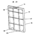
図23に示すように、保護フィルタ部45は、フィルタ支持枠46と、支骨47を縦横に設けた格子と、保持つめ48と、保護通気フィルタ49,保持突起101を有する。   As shown in FIG. 23, the protective filter unit 45 includes a filter support frame 46, a lattice in which support frames 47 are provided vertically and horizontally, a holding claw 48, a protective ventilation filter 49, and a holding projection 101.

フィルタ支持枠46と別体の保護通気フィルタ49は、支骨47と、保持つめ48とによりフィルタ支持枠46に保持される。   The protective ventilation filter 49, which is separate from the filter support frame 46, is held on the filter support frame 46 by a support frame 47 and a holding claw 48.

保護通気フィルタ49は、通気目が集塵袋7より粗く、フィルタ支持枠46の格子目よりも細やかで、可撓性を有する。フィルタ支持枠46の格子に添え当てた保護通気フィルタ49は、周縁を保持つめ48のところに差し込む。こうして、保護通気フィルタ49は、フィルタ支持枠46に保持される。   The protective ventilation filter 49 has a ventilation hole coarser than the dust collection bag 7, is finer than the lattice of the filter support frame 46, and has flexibility. The protective ventilation filter 49 attached to the grid of the filter support frame 46 is inserted into the holding pawl 48 at the periphery. Thus, the protective ventilation filter 49 is held by the filter support frame 46.

除塵枠体部20は、図16に示すように、下側に差込溝50を有する。この差込溝50は図23に示す保護フィルタ部45のフィルタ支持枠46の外周下側に配置される保持突起101が嵌め込まれる。   As shown in FIG. 16, the dust removing frame body portion 20 has an insertion groove 50 on the lower side. The insertion groove 50 is fitted with a holding projection 101 disposed on the lower outer periphery of the filter support frame 46 of the protective filter portion 45 shown in FIG.

保護フィルタ部45が取り付け,取り外しができるので、除塵部材150のメンテナンスに際しては、保護フィルタ部45を取り外すことで、保護通気フィルタ49をお手入れできる。保護フィルタ部45が着いていない合成樹脂製の除塵枠体部20は撓みやすく、除塵枠体部20の着脱が容易である。   Since the protective filter portion 45 can be attached and detached, the protective ventilation filter 49 can be maintained by removing the protective filter portion 45 during maintenance of the dust removing member 150. The dust-removing frame body portion 20 made of synthetic resin not attached with the protective filter portion 45 is easily bent, and the dust-removal frame portion 20 can be easily attached and detached.

この保護フィルタ部45は、内部流通口34上流側に位置する。集塵袋7が破れても、保護フィルタ部45により、塵埃が内部流通口34を通って電動送風機8に吸い込まれるのを防止できる。   The protection filter unit 45 is located upstream of the internal circulation port 34. Even if the dust bag 7 is torn, the protective filter unit 45 can prevent dust from being sucked into the electric blower 8 through the internal circulation port 34.

保護通気フィルタ49は、空気流の下流側面の周縁が保持つめ48で保持され、それに加え、縦置除塵体15の下流側枠体と中間仕切壁21に隣接される縦格子リブ35で抑えられるので、保護通気フィルタ49が除塵枠体部20及び保護フィルタ45から脱落する不具合は生じない。   In the protective ventilation filter 49, the peripheral edge of the downstream side surface of the air flow is held by the holding claw 48, and in addition, the protective ventilation filter 49 is suppressed by the vertical lattice rib 35 adjacent to the downstream frame body of the vertical dust removing body 15 and the intermediate partition wall 21. Therefore, the problem that the protective ventilation filter 49 falls off from the dust-removal frame body 20 and the protective filter 45 does not occur.

保護フィルタ部45は、図23に示すように、フィルタ支持枠46の上部の側端に突き出す取っ手51を有する。保護フィルタ部45の取り付け,取り外しでは、取っ手51を掴んで行う。   As shown in FIG. 23, the protective filter unit 45 has a handle 51 that protrudes from the upper side end of the filter support frame 46. The attachment / detachment of the protective filter unit 45 is performed by grasping the handle 51.

集塵室3の内底部は、図3に示すように、隆起している。掃除機本体ケース1の前側下面にキャスター52を取り付ける窪みを設けるために隆起させた。この隆起に合うように下部横置除塵体16の中央を隆起させ、かつ強度を高めた。   As shown in FIG. 3, the inner bottom portion of the dust collection chamber 3 is raised. The vacuum cleaner main body case 1 was raised to provide a recess for attaching the caster 52 to the front lower surface. The center of the lower horizontal dust removing body 16 was raised so as to match this elevation, and the strength was increased.

これにより、下部横置除塵体16と集塵室3の内定部間にできる無駄な空間は少なく、集塵室3内で集塵袋7がより大きく膨らみ、集塵量の増加を図ることができる。   As a result, there is little useless space between the lower horizontal dust remover 16 and the fixed portion of the dust collection chamber 3, and the dust collection bag 7 inflates in the dust collection chamber 3 to increase the amount of dust collection. it can.

次に除塵駆動伝達ユニット11の関連について説明する。   Next, the relationship of the dust removal drive transmission unit 11 will be described.

除塵駆動伝達ユニット11は、図25に示すように、支持フレーム73を有する。   As shown in FIG. 25, the dust removal drive transmission unit 11 has a support frame 73.

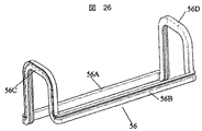
支持フレーム73は、矩形の枠体部53と、枠体部53の片側を塞ぐ底板部54と、枠体部53の短辺側に底板部54の反対側に向かって立つ二つの回転体支持板55を有する。   The support frame 73 includes a rectangular frame body portion 53, a bottom plate portion 54 that covers one side of the frame body portion 53, and two rotating body supports that stand on the short side of the frame body portion 53 toward the opposite side of the bottom plate portion 54. A plate 55 is provided.

二つの回転体支持板55の周端縁と、枠体部53の長辺側端縁には、気密シール56が設けられる。この気密シール56は、図26に示すように、連なった環に形成されている。連なった環の気密シール56は、つなぎ合わせの隙間がないので、シール性が高まり、かつ気密シールが変形し、確実な気密を確保することができる。   An airtight seal 56 is provided at the peripheral edge of the two rotating body support plates 55 and the long side edge of the frame body portion 53. The airtight seal 56 is formed in a continuous ring as shown in FIG. Since the hermetic seal 56 of the continuous ring does not have a gap for joining, the sealing performance is improved, and the hermetic seal is deformed to ensure a reliable hermetic seal.

気密シール56は、枠体部53と一体に合成樹脂で成型される。気密シール56は、シール機能を有するように枠体部53よりも軟質な合成樹脂で成型される。成型用の金型で成型された枠体部53を別の金型に移し、軟質の合成樹脂を注入することにより、枠体部53と気密シール56は一体に成型される。   The hermetic seal 56 is molded of synthetic resin integrally with the frame body portion 53. The hermetic seal 56 is molded of a synthetic resin softer than the frame body portion 53 so as to have a sealing function. The frame body portion 53 and the hermetic seal 56 are integrally molded by transferring the frame body portion 53 molded with a molding die to another mold and injecting a soft synthetic resin.

気密シール56は、枠体部73と分離して、ばらばらになることが生じないので、組立ての際の取り扱い性が向上する。また、気密シール56は軟質の合成樹脂で形成されるので、シール性が向上する。   Since the hermetic seal 56 does not separate from the frame body portion 73 and does not come apart, the handleability during assembly is improved. Moreover, since the hermetic seal 56 is formed of a soft synthetic resin, the sealing performance is improved.

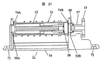
除塵駆動伝達ユニット11の除塵回転体12は、二つの回転体支持板55に回転自在に支持される。除塵回転体12は、図21に示すように、両端側に支軸74A,76Bを有する。   The dust removal rotary body 12 of the dust removal drive transmission unit 11 is rotatably supported by the two rotary body support plates 55. As shown in FIG. 21, the dust removal rotary body 12 has support shafts 74A and 76B on both ends.

伝達歯車13は、除塵回転体12の一方の端部側に設けられる。伝達歯車13の軸部57を除塵回転体12の一方の端部側にネジ等で締結して固定する。伝達歯車13は除塵回転体12の端部から離間したところに位置する。   The transmission gear 13 is provided on one end side of the dust removal rotary body 12. The shaft portion 57 of the transmission gear 13 is fastened and fixed to one end side of the dust removal rotary body 12 with a screw or the like. The transmission gear 13 is located away from the end of the dust removal rotary body 12.

除塵回転体12内には、一方向の回転が伝達され、他方向の回転が伝達されない、いわ
ゆる一方向回転伝達クラッチ58が備わる。コードリール9の駆動歯車14、および伝達歯車13を介してコードリール9の回転は、除塵回転体12に伝達される。
A so-called one-way rotation transmission clutch 58 is provided in the dust removal rotator 12 so that rotation in one direction is transmitted and rotation in the other direction is not transmitted. The rotation of the cord reel 9 is transmitted to the dust removal rotary body 12 via the drive gear 14 of the cord reel 9 and the transmission gear 13.

コードを引き出すときには除塵回転体12は回されるが、コードを巻き取るときには除
塵回転体12は回されない。こうすることにより、コードリール9の巻取りバネを小型化でき、しかもコードの引き出しが軽くなる。
The dust removal rotator 12 is rotated when the cord is pulled out, but the dust removal rotator 12 is not rotated when the cord is wound. By doing so, the winding spring of the cord reel 9 can be reduced in size, and the cord can be pulled out lightly.

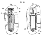
支持フレーム73の二つの回転体支持板55は、除塵回転体12の支軸74A,74Bを回転自在に支持する軸受59A,59Bを有する。伝達歯車13が設けられる支軸74Bを回転自在に支持する方の軸受59Bは、貫通するように形成される。   The two rotary body support plates 55 of the support frame 73 have bearings 59A and 59B that rotatably support the support shafts 74A and 74B of the dust removal rotary body 12. The bearing 59B that rotatably supports the support shaft 74B provided with the transmission gear 13 is formed so as to penetrate therethrough.

伝達歯車13が設けられない方の支軸74Aを支持する軸受59Aは、奥側が塞がるように形成される。軸受59Aは、奥側が塞がっているので、軸受59Aから回転体支持板55の外側に空気は漏れない。   The bearing 59A that supports the support shaft 74A on which the transmission gear 13 is not provided is formed so that the back side is closed. Since the inner side of the bearing 59A is closed, air does not leak from the bearing 59A to the outside of the rotating body support plate 55.

しかし、軸受59Bは貫通しているので、回転体支持板55の外側に空気は漏れる。そこで、回転体支持板55の外面側に、軸受59Bと支軸74Bの隙間を封じる軸シール60を設けた。この軸シール60により、軸受59Bを通じて回転体支持板55の外側に漏れる空気漏洩は阻止される。   However, since the bearing 59B penetrates, the air leaks to the outside of the rotating body support plate 55. Therefore, a shaft seal 60 for sealing the gap between the bearing 59B and the support shaft 74B is provided on the outer surface side of the rotating body support plate 55. The shaft seal 60 prevents air leakage from leaking to the outside of the rotating body support plate 55 through the bearing 59B.

図13に示すように、掃除機本体ケース1は底面に除塵駆動伝達ユニット11が装着される装着開口部61を有する。この装着開口部61には、除塵駆動伝達ユニット11が外側から着脱自在に装着される。   As shown in FIG. 13, the cleaner body case 1 has a mounting opening 61 in which the dust removal drive transmission unit 11 is mounted on the bottom surface. The dust removal drive transmission unit 11 is detachably attached to the attachment opening 61 from the outside.

このように、支持フレーム73に除塵回転体12,伝達歯車13をまとめてユニット化し、ユニットになった除塵駆動伝達ユニット11を掃除機本体ケース1の装着開口部61に取り付けるので、組立てが容易に行われる。   In this way, the dust removal rotary body 12 and the transmission gear 13 are integrated into a unit on the support frame 73, and the dust removal drive transmission unit 11 as a unit is attached to the mounting opening 61 of the cleaner body case 1, so that assembly is easy. Done.

装着開口部61は、除塵回転体12や支持フレーム73が置かれるところには窪み部62が形成され、伝達歯車13が置かれるところには後部室(コードリール9,電動送風機8が置かれる)側に臨む開口が形成されている。   The mounting opening 61 has a recess 62 where the dust removing rotator 12 and the support frame 73 are placed, and a rear chamber (where the code reel 9 and the electric blower 8 are placed) where the transmission gear 13 is placed. An opening facing the side is formed.

窪み部62は、図27に示すように、奥側に除塵用開口63を有する。この除塵用開口63は、集塵室3内に置かれる縦置除塵体15の下端側に臨んでいる。   As shown in FIG. 27, the recess 62 has a dust removal opening 63 on the back side. The dust removal opening 63 faces the lower end side of the vertical dust remover 15 placed in the dust collection chamber 3.

また、窪み部62は、伝達歯車13が位置する方の側面側に伝達開口64を有する。この伝達開口64を介して窪み部62は、後部室側と連通している。   Further, the recess 62 has a transmission opening 64 on the side surface where the transmission gear 13 is located. The recess 62 communicates with the rear chamber side through the transmission opening 64.

装着開口部61に装着された除塵駆動伝達ユニット11の除塵回転体12は、外周側の除塵バネ31が除塵用開口63から集塵室3に突き出し、縦置除塵体15の下端側(円弧面の当接部)に当接する。   In the dust removing rotary body 12 of the dust removing drive transmission unit 11 mounted in the mounting opening 61, the dust removing spring 31 on the outer peripheral side protrudes from the dust removing opening 63 into the dust collecting chamber 3, and the lower end side of the vertical dust removing body 15 (arc surface) Abutting part).

伝達歯車13は、コードリール9の駆動歯車13に噛み合わされる。伝達歯車13の軸部57は、伝達開口64に置かれる。   The transmission gear 13 is meshed with the drive gear 13 of the cord reel 9. The shaft portion 57 of the transmission gear 13 is placed in the transmission opening 64.

窪み部62は、図27,図28に示すように、窪み部62の底に近い低位置段部65と、底から離れた高位置段部66とを有する。また、窪み部62は、長手方向の端側に接合突起67,68を有する。   As shown in FIGS. 27 and 28, the recess 62 has a low position step 65 near the bottom of the recess 62 and a high position step 66 far from the bottom. Moreover, the hollow part 62 has joining protrusions 67 and 68 on the end side in the longitudinal direction.

窪み部62の低位置段部65には、気密シール56の辺56Bが当接する。窪み部62の高位置段部66には、気密シール56の辺56Aが当接する。接合突起68には、気密シール56の辺56Cが当接する。接合突起67には、気密シール56の辺56Dが当接する。   The side 56 </ b> B of the hermetic seal 56 abuts on the lower position step portion 65 of the recess 62. The side 56 </ b> A of the hermetic seal 56 abuts on the high position step portion 66 of the recess 62. A side 56 </ b> C of the hermetic seal 56 abuts on the joint protrusion 68. The side 56D of the hermetic seal 56 abuts on the joint protrusion 67.

これらの当接による気密シール56のシールにより、除塵用開口63を通じ、集塵室3と掃除機本体ケース1の外側間で空気が流通するのは断たれる。このため、装着開口部61を通じて集塵室3と掃除機本体ケース1の外側間で空気が流れる空気漏れは生じない。   By the sealing of the airtight seal 56 by the contact, air is prevented from flowing between the dust collection chamber 3 and the outside of the cleaner body case 1 through the dust removal opening 63. For this reason, there is no air leakage through which air flows between the dust collection chamber 3 and the outside of the cleaner body case 1 through the mounting opening 61.

また、気密シール56は、窪み部62が伝達開口64を介して後部室(コードリール9,電動送風機8が置かれる)に連通するところのシールを併せてしている。このため、集塵室3と後部室の間も空気の流通は断たれ、空気漏れは生じない。   The hermetic seal 56 also includes a seal where the recess 62 communicates with the rear chamber (where the code reel 9 and the electric blower 8 are placed) via the transmission opening 64. For this reason, air circulation is also cut off between the dust collection chamber 3 and the rear chamber, and no air leakage occurs.

図28の(a)は、電気掃除機本体の装着開口部61に装着されている除塵駆動伝達ユニットを横方向に断面したところを示している。   (A) of FIG. 28 has shown the place which carried out the cross section in the horizontal direction of the dust removal drive transmission unit with which the installation opening part 61 of the vacuum cleaner main body was mounted | worn.

図28の(b)は、除塵駆動伝達ユニット11を装着開口部61から外したところを示している。窪み部62の底に除塵用開口63が見える。また、接合突起67,68は、図示されていないが、二つの回転体支持板55のところに位置する。   FIG. 28 (b) shows the dust removal drive transmission unit 11 removed from the mounting opening 61. A dust removal opening 63 is visible at the bottom of the recess 62. Further, although not shown, the joint protrusions 67 and 68 are located at the two rotating body support plates 55.

窪み部62に内側面に突出するように設けられた接合突起67,68は、幅が気密シール56の幅よりも狭い。接合突起67,68に押圧された気密シール56を押し付けることにより、接合突起67,68が気密シール56に食い込み気密が向上する。   The joint protrusions 67 and 68 provided so as to protrude from the inner surface of the recess 62 are narrower than the width of the hermetic seal 56. By pressing the airtight seal 56 pressed against the joint protrusions 67 and 68, the joint protrusions 67 and 68 bite into the airtight seal 56 and the airtightness is improved.

除塵駆動伝達ユニット11は、掃除機本体ケース1に設けたねじボス69,70にねじ込むネジにより締め付け固定される。除塵駆動伝達ユニット11に設けたネジ通穴71,72は、二つの回転体支持板55の外側に設けた。   The dust removal drive transmission unit 11 is fastened and fixed by screws screwed into screw bosses 69 and 70 provided in the cleaner body case 1. The screw through holes 71 and 72 provided in the dust removal drive transmission unit 11 are provided outside the two rotating body support plates 55.

二つの回転体支持板55の内側にネジ通穴を設けると、ネジ通穴にも気密を施さなければならない。ネジ通穴を二つの回転体支持板55の外側に設けることにより、気密を施す必要がなく、構成が簡単になる。   If screw through holes are provided inside the two rotating body support plates 55, the screw through holes must be airtight. By providing the screw through holes on the outer sides of the two rotating body support plates 55, it is not necessary to provide airtightness and the configuration is simplified.

次に、本発明の第2の実施例について、図4,図6を引用して説明する。図6に示すように、集塵室3の隔壁103によって構成される溝部102に気密が保持されるように気密部材10の複数の突起部100が挿入され気密を保持している。   Next, a second embodiment of the present invention will be described with reference to FIGS. As shown in FIG. 6, a plurality of protrusions 100 of the airtight member 10 are inserted and kept airtight so that the groove 102 constituted by the partition wall 103 of the dust collecting chamber 3 is kept airtight.

気密部材10の複数の突起部100のうち、集塵室3に対して最も内側に位置する第一の突起部100aの側面と集塵室3と面一若しくは外側になるように構成した気密部材10の内側面111には段差を設け、集塵室3の最も内側を構成する第一の隔壁103aの内側面112と同一面にすることによって、集塵袋(紙パック)7及び集塵ケースの着脱性が向上する。   Among the plurality of protrusions 100 of the airtight member 10, the airtight member is configured to be flush with or outside the side surface of the first protrusion 100 a located on the innermost side with respect to the dust collection chamber 3 and the dust collection chamber 3. 10 is provided with a step so that it is flush with the inner side surface 112 of the first partition wall 103a that forms the innermost side of the dust collecting chamber 3, so that a dust bag (paper pack) 7 and a dust collecting case are provided. Detachability is improved.

また、第一の実施例に示した集塵室3と気密部材10の気密保持の形状を構成しようと考えた場合、少なくとも3つの隔壁から2つの溝部102を構成し、気密部材10から複数の突起部100を溝部102にテーパー勘合し、気密を保持する構成をとった場合に、
気密部材10の第一の突起部100aの側面と集塵室3の最も内側を構成する第一の隔壁103aの内側面112とを同一面、つまり気密部材10に前述したように段差を設けることにより、隔壁103の構成が最も単純で、本体自体を軽量コンパクトに構成することができ、製品としてスリム化することができる。
Further, when it is considered to form the airtight holding shape of the dust collection chamber 3 and the airtight member 10 shown in the first embodiment, the two groove portions 102 are formed from at least three partition walls, and a plurality of airtight members 10 When the projecting portion 100 is taper fitted into the groove portion 102 and is configured to maintain airtightness,
The side surface of the first protrusion 100a of the airtight member 10 and the inner surface 112 of the first partition wall 103a constituting the innermost side of the dust collecting chamber 3 are provided on the same surface, that is, the airtight member 10 is provided with a step as described above. Therefore, the configuration of the partition wall 103 is the simplest, the main body itself can be configured to be lightweight and compact, and the product can be slimmed.

また、本体自体の構成の簡略化が実現できるため成形材料を総合的に削減することが出来き、更には省資源化を図ることができ環境にも優しい。   In addition, since the configuration of the main body itself can be simplified, molding materials can be reduced comprehensively, and further resource saving can be achieved, which is environmentally friendly.

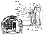
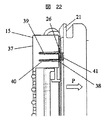
次に、本発明の第3の実施例について、図29,図30を引用して説明する。   Next, a third embodiment of the present invention will be described with reference to FIGS.

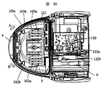
図30に示すように、掃除機本体を運転させる際には、近年の掃除機では掃除機本体ケース1にホース差込口4を挿入し、ホース体(図示せず)の手元操作部によって本体電源の入切り及びホース体先端に接続される延長管(図示せず)を介して接続される吸込口体(図示せず)の電動回転ブラシの電源のON,OFFを手元操作部によって行われるのが一般的である。   As shown in FIG. 30, when operating the vacuum cleaner main body, in recent vacuum cleaners, the hose insertion port 4 is inserted into the vacuum cleaner main body case 1 and the main body is operated by the hand operating part of the hose body (not shown). On / off of the electric rotating brush of the suction port body (not shown) connected via an extension pipe (not shown) connected to the tip of the hose body is turned on and off by the hand operation unit. It is common.

ホース差込口4及びホース体(図示せず)及び延長管(図示せず)及び吸口体(図示せず)の各接続部には、導電性のよい接触片が備わっており、それらを接続することによって本体からの各部品(電動回転ブラシ用吸込口等)への電源供給を可能にする。   Each connection part of the hose insertion port 4 and the hose body (not shown), the extension pipe (not shown) and the suction body (not shown) is provided with a contact piece having good conductivity, and these are connected. By doing so, it is possible to supply power from the main body to each component (such as a suction port for an electric rotating brush).

通常、掃除機本体ケース1の前側部にはホース差込口、後ろ側には手元操作部への信号と電源供給、電動送風機への電源供給等を制御する本体コントロールキバン120を備える。   In general, the front side of the vacuum cleaner main body case 1 is provided with a hose insertion port, and the rear side is provided with a main body control base 120 for controlling a signal and power supply to the hand operating unit, power supply to the electric blower, and the like.

本体コントロールキバン120からホース差込口4の接触片(図示せず)まで電源及び信号を伝えるために給電線121を設ける。   A power supply line 121 is provided to transmit power and signals from the main body control hub 120 to the contact piece (not shown) of the hose insertion port 4.

給電線121は、集塵室3の第二の隔壁103bと第三の隔壁103cにより形成される第二の溝部100bに配線され、第二の溝部100bと気密部材10の第二の突起部100bにより構成されるすき間によって配線される。   The power supply line 121 is wired to the second groove portion 100 b formed by the second partition wall 103 b and the third partition wall 103 c of the dust collection chamber 3, and the second groove portion 100 b and the second protrusion portion 100 b of the airtight member 10. It is wired by the gap constituted by.

気密部材10の第二の突起部100bの下側に配線することによって、給電線121が第二の溝部100bから浮いて外れてしまうことを防止することが出来る。   By wiring below the second protrusion 100b of the hermetic member 10, it is possible to prevent the power supply line 121 from floating off the second groove 100b.

また第二の突起部100bは給電線121の略全線を覆っているので、仮に給電線121の被覆が傷つき、電線がむき出しになっても、使用者が触れて、ケガや感電する恐れが少ない。   In addition, since the second protrusion 100b covers substantially the entire line of the power supply line 121, even if the coating of the power supply line 121 is damaged and the electric wire is exposed, there is little risk of injury or electric shock by the user touching it. .

また、突起部を一体に形成する気密部材10は、ゴム素材をベースとした弾性体により形成されているため、絶縁性も高い。   Moreover, since the airtight member 10 that integrally forms the protrusions is formed of an elastic body based on a rubber material, the insulating property is also high.

更に、気密部材10はゴム素材をベースとした柔らかい弾性体により形成されているため、組み立て上、集塵室3の第二の溝部100bに給電線121を配線し、その後に気密部材10の第二の突起部100bにより押し込んでも、ゴム素材をベースとした弾性体により形成されているため、電線の被覆がはがれる可能性も低い。   Further, since the airtight member 10 is formed of a soft elastic body based on a rubber material, the power supply line 121 is wired in the second groove portion 100b of the dust collecting chamber 3 for assembly, and then the second member of the airtight member 10 is assembled. Even if it pushes in by the 2nd protrusion part 100b, since it is formed with the elastic body based on the rubber raw material, possibility that the coating | coated of an electric wire will be peeled is also low.

また、気密部材10の第二の突起部100bの先端はエッジではなく、角Rがとれているのが望ましい。   Further, it is desirable that the tip of the second protrusion 100b of the airtight member 10 is not an edge but a corner R.

図30より集塵室3の外周部に形成される給電線121を配線する第二の溝部100bの配線方向はA方向から配線しても、B方向から配線してもよい。   From FIG. 30, the wiring direction of the second groove portion 100b for wiring the power supply line 121 formed on the outer peripheral portion of the dust collecting chamber 3 may be wired from the A direction or from the B direction.

ホース差込口4側から配線された給電線121を第二の溝部100bから溝切り欠き部122を通して本体コントロールキバン120上のコネクタと接続される。   The feeder line 121 wired from the hose insertion port 4 side is connected to the connector on the main body control hub 120 through the groove cutout portion 122 from the second groove portion 100b.

溝切り書き部120が複数個ある場合には例えば図30に示すように溝切り欠き部120aから給電線121を通しても、120bから給電線121を出してもよい。   In the case where there are a plurality of groove notch parts 120, for example, as shown in FIG. 30, the power feed line 121 may be extended from the groove notch part 120a through the power feed line 121 or from 120b.

切り欠き部120は給電線121の被覆が傷つかないように、角Rは出来るだけ大きめにとるのが望ましい。   It is desirable that the notch 120 has a corner R as large as possible so that the coating of the power supply line 121 is not damaged.

給電線121は、通常の電線(丸形ケーブル)でもフラットケーブルでもよく、接続する両端部は導電性のよい接触片若しくはコネクタが接続されている。   The power supply line 121 may be a normal electric wire (round cable) or a flat cable, and a contact piece or a connector having good conductivity is connected to both ends to be connected.

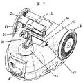
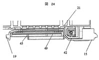
次に、本発明の第4の実施例について、図31,図32を引用して説明する。図31に示すように、集塵室3の電動送風機8側の隔壁103の天井面は、略円弧形状を形成しており、また溝部102にテーパー合している気密部材10も集塵室3の隔壁103の天井面に沿った形状で気密に合されている。蓋体5に一体に形成されている気密リブ108も同様に気密部材10の円弧形状に沿ったかたちで形成し、天井面105に気密に干渉又は接している。

Next, a fourth embodiment of the present invention will be described with reference to FIGS. As shown in FIG. 31, the ceiling surface of the partition wall 103 on the electric blower 8 side of the dust collection chamber 3 has a substantially arc shape, and the airtight member 10 taper- fitted to the groove 102 is also the dust collection chamber. The three partition walls 103 are fitted in an airtight manner along the ceiling surface. Similarly, the airtight rib 108 formed integrally with the lid 5 is also formed in a shape along the arc shape of the airtight member 10, and airtightly interferes or contacts the ceiling surface 105.

円弧状の部分の集塵室3の隔壁103が形成する溝部102と気密部材10の突起部100の構成する空間には、給電線が配線されている。   In the space formed by the groove portion 102 formed by the partition wall 103 of the dust collection chamber 3 in the arc-shaped portion and the projection portion 100 of the airtight member 10, a feeder line is wired.

また、電動送風機8側の集塵室3の隔壁によって構成される第二の溝部102bには、気密部材10の第二の突起部100bが挿入されるが、電動送風機8側には、緩衝部110が一体に形成されないために、第二の突起部100bの先端に先端突起部100dを設け、上部ケース130の端面131で突起を第二の溝部100bに向かって押さえることにより、気密部材10の第二の突起部100bの第二の溝部100bからの浮き上がりを防止することが出来る。   The second protrusion 100b of the airtight member 10 is inserted into the second groove portion 102b configured by the partition wall of the dust collecting chamber 3 on the electric blower 8 side, but the buffer portion is provided on the electric blower 8 side. Since 110 is not integrally formed, a tip protrusion 100d is provided at the tip of the second protrusion 100b, and the protrusion is pressed toward the second groove 100b by the end surface 131 of the upper case 130, whereby the airtight member 10 is provided. It is possible to prevent the second protrusion 100b from being lifted from the second groove 100b.

また、電動送風機8側の隔壁103の構成する第二の溝部100bには切り欠き部122があり、他の溝部102の範囲よりも給電線が切り欠き部を通っているため、他の溝部102の範囲よりも気密部材10を浮かせる方向に働く力が大きく、また浮き上がる可能性が高い。従って、電動送風機8側の範囲においては、上部ケース130の端面131で先端突起部100dを押さえ、また先端突起部100dを押さえる上部ケースは複数箇所を集塵室3とねじ等で確実に固定することによって、気密部材10の外れ防止はもとより、更にはより高い気密が保たれる。   In addition, the second groove portion 100b constituting the partition wall 103 on the electric blower 8 side has a notch portion 122, and the feeder line passes through the notch portion as compared with the range of the other groove portion 102. The force acting in the direction in which the airtight member 10 is floated is larger than the above range, and there is a high possibility that it will float. Accordingly, in the range on the electric blower 8 side, the tip protrusion portion 100d is pressed by the end surface 131 of the upper case 130, and the upper case pressing the tip protrusion portion 100d is securely fixed at a plurality of locations with the dust collection chamber 3 and screws. As a result, not only can the airtight member 10 be prevented from being detached, but also higher airtightness can be maintained.

また、電動送風機8側の集塵室3の隔壁103は、本体運転時に集塵室3が負圧になり隔壁103全体が内側に引っ張られ、撓みを生じる中、最も撓みが大きい部分である、電動送風機8側の隔壁103の天井面を円弧状にすることによって、集塵室3側への隔壁の倒れ込みを改善し、また、気密部材10の先端突起部100dを押さえる上部ケースの端面131が同時に最も外側の隔壁(図中では第三の隔壁103c)を同時に押さえることにより、更に隔壁103の集塵室3内側への倒れ込みを抑制している。   Further, the partition wall 103 of the dust collection chamber 3 on the electric blower 8 side is a portion having the largest deflection, while the dust collection chamber 3 becomes negative pressure during operation of the main body and the entire partition wall 103 is pulled inward to cause deflection. By making the ceiling surface of the partition wall 103 on the electric blower 8 side into an arc shape, the falling of the partition wall to the dust collecting chamber 3 side is improved, and the end surface 131 of the upper case that holds down the tip protrusion 100d of the airtight member 10 is provided. At the same time, the outermost partition wall (third partition wall 103c in the figure) is simultaneously pressed to further prevent the partition wall 103 from falling into the dust collection chamber 3.

これにより集塵室3の気密性を大幅に向上することが可能となる。   As a result, the airtightness of the dust collecting chamber 3 can be greatly improved.

本発明の一実施例に係る電気掃除機本体の外観斜視図である。It is an external appearance perspective view of the vacuum cleaner main body which concerns on one Example of this invention. 本発明の一実施例に係る集塵蓋体が開かれた状態を示す電気掃除機本体の外観斜視図である。It is an external appearance perspective view of the vacuum cleaner main body which shows the state by which the dust collecting cover which concerns on one Example of this invention was opened. 本発明の一実施例に係る電気掃除機本体の断面図である。It is sectional drawing of the vacuum cleaner main body which concerns on one Example of this invention. 本発明の一実施例に係る気密部材の断面図である。It is sectional drawing of the airtight member which concerns on one Example of this invention. 本発明の一実施例に係る集塵室の断面図である。It is sectional drawing of the dust collection chamber which concerns on one Example of this invention. 本発明の一実施例に係る電気掃除機本体の気密部材付近の横断面図と部分拡大図である。It is the cross-sectional view and partial enlarged view of the airtight member vicinity of the vacuum cleaner main body which concerns on one Example of this invention. 本発明の一実施例に係る除塵駆動伝達ユニットの取り付けを示した斜視図である。It is the perspective view which showed attachment of the dust removal drive transmission unit which concerns on one Example of this invention. 本発明の一実施例に係る上部横置除塵体の斜視図である。1 is a perspective view of an upper horizontal dust remover according to an embodiment of the present invention. 本発明の一実施例に係る縦置除塵体の斜視図である。It is a perspective view of the vertical dust removal body which concerns on one Example of this invention. 本発明の一実施例に係る下部横置除塵体の斜視図である。It is a perspective view of a lower horizontal dust remover according to an embodiment of the present invention. 本発明の一実施例に係る除塵部材への動力伝達を示す図である。It is a figure which shows the motive power transmission to the dust removal member which concerns on one Example of this invention. 本発明の一実施例に係り、開かれた除塵部材と折り畳まれた除塵部材を側面から見たところを示す図である。It is a figure which shows the place which looked at the opened dust removal member and the folded dust removal member from the side surface in one Example of this invention. 本発明の一実施例に係るシタケースを側面から見た図である。It is the figure which looked at the case which concerns on one Example of this invention from the side. 本発明の一実施例に係る支持リブ22を拡大した図である。It is the figure which expanded the support rib 22 which concerns on one Example of this invention. 本発明の一実施例に係る動力分岐機構を示す図である。It is a figure which shows the power branch mechanism which concerns on one Example of this invention. 本発明の一実施例に係る除塵部材を背面から見た斜視図である。It is the perspective view which looked at the dust removal member concerning one example of the present invention from the back. 本発明の一実施例に係る上部除塵部材を前から見た断面図である。It is sectional drawing which looked at the upper dust removal member which concerns on one Example of this invention from the front. 本発明の一実施例に係る上部除塵部材を横から見た断面図である。It is sectional drawing which looked at the upper dust removal member which concerns on one Example of this invention from the side. 本発明の一実施例に係る上部横置除塵体補助部の斜視図及び部分断面図である。It is the perspective view and partial sectional view of an upper horizontal dust removing body auxiliary part according to an embodiment of the present invention. 本発明の一実施例に係る除塵部材の正面図である。It is a front view of a dust removal member concerning one example of the present invention. 本発明の一実施例に係る除塵駆動伝達ユニットの断面図である。It is sectional drawing of the dust removal drive transmission unit which concerns on one Example of this invention. 本発明の一実施例に係る縦置除塵体のバネ取付け部の部分断面図である。It is a fragmentary sectional view of the spring attachment part of the vertical dust remover which concerns on one Example of this invention. 本発明の一実施例に係る保護フィルタ部を示した斜視図である。It is the perspective view which showed the protection filter part which concerns on one Example of this invention. 本発明の一実施例に係る縦置除塵体と保護フィルタ部を横方向に断面した一部拡大図である。It is the partially expanded view which carried out the cross section in the horizontal direction of the vertical dust removal body and protection filter part which concern on one Example of this invention. 本発明の一実施例に係る除塵回転体を除いた除塵駆動伝達ユニットを示す図である。It is a figure which shows the dust removal drive transmission unit except the dust removal rotary body which concerns on one Example of this invention. 本発明の一実施例に係る気密シールを示す図である。It is a figure which shows the airtight seal which concerns on one Example of this invention. 本発明の一実施例に係る除塵用開口を示した図である。It is the figure which showed the opening for dust removal which concerns on one Example of this invention. 本発明の一実施例に係る除塵駆動伝達ユニットが電気掃除機本体に装着されているところを断面した図と、除塵駆動伝達ユニットが外された電気掃除機本体の装着開口部を正面から見た図である。The figure which looked at the place where the dust removal drive transmission unit concerning one example of the present invention was installed in the vacuum cleaner main part, and the attachment opening part of the vacuum cleaner main body from which the dust removal drive transmission unit was removed was seen from the front. FIG. 本発明の一実施例に係る本体の垂直断面をとり、集塵室隔壁付近を拡大した図である。It is the figure which took the vertical cross section of the main body which concerns on one Example of this invention, and expanded the dust collection chamber partition vicinity. 本発明の一実施例に係る気密部材,上部ケース,ハンドル,蓋体を外し、給電線の経路を見やすくした本体の上面図である。1 is a top view of a main body in which an airtight member, an upper case, a handle, and a lid according to an embodiment of the present invention are removed to make a path of a power supply line easy to see. 本発明の一実施例に係る蓋体を開いた状態の本体の正面図である。It is a front view of the main body of the state which opened the cover concerning one example of the present invention. 本発明の一実施例に係る気密部材と上部ケース、集塵室を組み合わせた中央断面図である。It is a central sectional view combining an airtight member, an upper case, and a dust collecting chamber according to an embodiment of the present invention. 本発明の一実施例に係る除塵駆動伝達ユニットと電動機との組みつけを示した図である。It is the figure which showed the assembly | attachment of the dust removal drive transmission unit and electric motor which concern on one Example of this invention.

符号の説明Explanation of symbols

10 気密部材
100 突起部
100a 第一の突起部
100b 第二の突起部
102a 第一の溝部
102b 第二の溝部
103a 第一の隔壁
103b 第二の隔壁
103c 第三の隔壁
110 緩衝部
10 airtight member 100 projection 100a first projection 100b second projection 102a first groove 102b second groove 103a first partition 103b second partition 103c third partition 110 buffer

Claims (4)

電動送風機及び集塵室を備えた掃除機本体と、該掃除機本体に設けられ、前記集塵室を開閉自在に覆うように設けられた蓋体と、前記集塵室と前記蓋体とを気密に保持する気密部材を備えた電気掃除機において、
前記気密部材は複数の突起部と、該突起部と一体に形成された緩衝部とを備え、
前記集塵室は少なくともその外周部に垂直方向に立ち上がった少なくとも3つの隔壁を有し、
前記気密部材のうち集塵室側に位置する部分は、前記少なくとも3つの隔壁のうち最も内側に位置する隔壁と略面一かもしくは前記少なくとも3つの隔壁のうち最も内側に位置する隔壁よりも外側になるように位置させ、
前記少なくとも3つの隔壁間には、少なくとも2つの溝部が形成され、該溝部には前記複数の突起部が挿入され、前記少なくとも3つの隔壁のうち最も外側に位置した隔壁は、前記複数の突起部と一体に形成された緩衝部で覆われたことを特徴とする電気掃除機。
A vacuum cleaner main body provided with an electric blower and a dust collection chamber, a lid provided in the vacuum cleaner main body so as to cover the dust collection chamber so as to be openable and closable, and the dust collection chamber and the lid In an electric vacuum cleaner equipped with an airtight member that holds airtightly,
The airtight member includes a plurality of protrusions and a buffer part integrally formed with the protrusions,
The dust collection chamber has at least three partition walls standing vertically at least on the outer periphery thereof,
The portion of the airtight member located on the dust collection chamber side is substantially flush with the innermost partition of the at least three partition walls , or more than the innermost partition of the at least three partitions. Position it to the outside,
At least two groove portions are formed between the at least three partition walls, the plurality of protrusions are inserted into the groove portions, and the outermost partition wall of the at least three partition walls is the plurality of protrusion portions. A vacuum cleaner characterized in that it is covered with a buffer part formed integrally.
請求項1において、
前記気密部材のうち集塵室側に位置する部分と、前記複数の突起のうち内側の溝に挿入される突起とには段差部が形成され、該段差部に前記少なくとも3つの隔壁のうち最も内側に位置する隔壁を位置させたことを特徴とする電気掃除機。
In claim 1,
A step portion is formed in a portion of the airtight member located on the dust collecting chamber side and a projection inserted into an inner groove among the plurality of projections, and the step portion is the most of the at least three partition walls. The vacuum cleaner characterized by having located the partition located inside.
請求項1又は請求項2において、
前記隔壁により構成される溝部に給電線を配線したことを特徴とする電気掃除機。
In claim 1 or claim 2,
A vacuum cleaner characterized in that a power supply line is wired in a groove portion constituted by the partition wall.
請求項1乃至3の何れかにおいて、
電動送風機側の隔壁及び気密部材の上面形状は、略円弧状としたことを特徴とす電気掃除機。
In any one of Claims 1 thru | or 3,
The shape of the upper surface of the electric blower side of the partition wall and the airtight member, the electric vacuum cleaner you characterized in that a substantially arc shape.
JP2007180447A 2007-07-10 2007-07-10 Electric vacuum cleaner Expired - Fee Related JP5118908B2 (en)

Priority Applications (1)

Application Number Priority Date Filing Date Title
JP2007180447A JP5118908B2 (en) 2007-07-10 2007-07-10 Electric vacuum cleaner

Applications Claiming Priority (1)

Application Number Priority Date Filing Date Title
JP2007180447A JP5118908B2 (en) 2007-07-10 2007-07-10 Electric vacuum cleaner

Publications (2)

Publication Number Publication Date
JP2009017903A JP2009017903A (en) 2009-01-29
JP5118908B2 true JP5118908B2 (en) 2013-01-16

Family

ID=40358076

Family Applications (1)

Application Number Title Priority Date Filing Date
JP2007180447A Expired - Fee Related JP5118908B2 (en) 2007-07-10 2007-07-10 Electric vacuum cleaner

Country Status (1)

Country Link
JP (1) JP5118908B2 (en)

Family Cites Families (3)

* Cited by examiner, † Cited by third party
Publication number Priority date Publication date Assignee Title
JPH02168922A (en) * 1988-12-23 1990-06-29 Tokyo Electric Co Ltd vacuum cleaner
JPH047037U (en) * 1990-05-09 1992-01-22
JPH08215113A (en) * 1995-02-20 1996-08-27 Hitachi Ltd Electric vacuum cleaner

Also Published As

Publication number Publication date
JP2009017903A (en) 2009-01-29

Similar Documents

Publication Publication Date Title
KR102129021B1 (en) Surface cleaning head with double rotating agitator
JP4444043B2 (en) Vacuum cleaner
JP2009504311A (en) Vacuum cleaner
JP5075738B2 (en) Electric vacuum cleaner
JP5118908B2 (en) Electric vacuum cleaner
JP4928847B2 (en) Vacuum cleaner
JP2008005864A (en) Vacuum cleaner
JP2006095062A (en) Electric vacuum cleaner
JP4550692B2 (en) Vacuum cleaner
CN102908104B (en) Electric dust collector
CN101288573B (en) electric vacuum cleaner
JP4673166B2 (en) Electric vacuum cleaner
JP4602873B2 (en) Vacuum cleaner
JPH0251B2 (en)
JP2007029628A (en) Electric vacuum cleaner
CN100393267C (en) electric vacuum cleaner
JP5272766B2 (en) Electric vacuum cleaner
JPS6058647B2 (en) vacuum cleaner
JP2017213158A (en) Electric vacuum cleaner
KR101741147B1 (en) A vacuum cleaner with a detachable dust gathering bag catridge
JP2011041619A (en) Dust collector and vacuum cleaner
JP2011000394A (en) Dust collector and vacuum cleaner
JP5530287B2 (en) Electric vacuum cleaner
JP6607131B2 (en) Suction tool and vacuum cleaner provided with the same
JPS59141918A (en) Electric cleaner

Legal Events

Date Code Title Description
A621 Written request for application examination

Free format text: JAPANESE INTERMEDIATE CODE: A621

Effective date: 20090930

A521 Request for written amendment filed

Free format text: JAPANESE INTERMEDIATE CODE: A523

Effective date: 20090930

A977 Report on retrieval

Free format text: JAPANESE INTERMEDIATE CODE: A971007

Effective date: 20110808

A131 Notification of reasons for refusal

Free format text: JAPANESE INTERMEDIATE CODE: A131

Effective date: 20110816

A521 Request for written amendment filed

Free format text: JAPANESE INTERMEDIATE CODE: A523

Effective date: 20111006

A131 Notification of reasons for refusal

Free format text: JAPANESE INTERMEDIATE CODE: A131

Effective date: 20120104

TRDD Decision of grant or rejection written
A01 Written decision to grant a patent or to grant a registration (utility model)

Free format text: JAPANESE INTERMEDIATE CODE: A01

Effective date: 20120925

A01 Written decision to grant a patent or to grant a registration (utility model)

Free format text: JAPANESE INTERMEDIATE CODE: A01

A61 First payment of annual fees (during grant procedure)

Free format text: JAPANESE INTERMEDIATE CODE: A61

Effective date: 20121022

R150 Certificate of patent or registration of utility model

Free format text: JAPANESE INTERMEDIATE CODE: R150

Ref document number: 5118908

Country of ref document: JP

Free format text: JAPANESE INTERMEDIATE CODE: R150

FPAY Renewal fee payment (event date is renewal date of database)

Free format text: PAYMENT UNTIL: 20151026

Year of fee payment: 3

S531 Written request for registration of change of domicile

Free format text: JAPANESE INTERMEDIATE CODE: R313531

S533 Written request for registration of change of name

Free format text: JAPANESE INTERMEDIATE CODE: R313533

R350 Written notification of registration of transfer

Free format text: JAPANESE INTERMEDIATE CODE: R350

LAPS Cancellation because of no payment of annual fees