JP5123665B2 - Pre-shaped ablation catheter for excising the pulmonary vein opening of the heart - Google Patents
Pre-shaped ablation catheter for excising the pulmonary vein opening of the heart Download PDFInfo
- Publication number
- JP5123665B2 JP5123665B2 JP2007539338A JP2007539338A JP5123665B2 JP 5123665 B2 JP5123665 B2 JP 5123665B2 JP 2007539338 A JP2007539338 A JP 2007539338A JP 2007539338 A JP2007539338 A JP 2007539338A JP 5123665 B2 JP5123665 B2 JP 5123665B2
- Authority
- JP
- Japan
- Prior art keywords
- catheter
- curve
- distal
- proximal
- section
- Prior art date
- Legal status (The legal status is an assumption and is not a legal conclusion. Google has not performed a legal analysis and makes no representation as to the accuracy of the status listed.)
- Expired - Fee Related
Links
Images




Classifications
-
- A—HUMAN NECESSITIES
- A61—MEDICAL OR VETERINARY SCIENCE; HYGIENE
- A61B—DIAGNOSIS; SURGERY; IDENTIFICATION
- A61B18/00—Surgical instruments, devices or methods for transferring non-mechanical forms of energy to or from the body
- A61B18/04—Surgical instruments, devices or methods for transferring non-mechanical forms of energy to or from the body by heating
- A61B18/12—Surgical instruments, devices or methods for transferring non-mechanical forms of energy to or from the body by heating by passing a current through the tissue to be heated, e.g. high-frequency current
- A61B18/14—Probes or electrodes therefor
- A61B18/1492—Probes or electrodes therefor having a flexible, catheter-like structure, e.g. for heart ablation
-
- A—HUMAN NECESSITIES
- A61—MEDICAL OR VETERINARY SCIENCE; HYGIENE
- A61B—DIAGNOSIS; SURGERY; IDENTIFICATION
- A61B5/00—Measuring for diagnostic purposes; Identification of persons
- A61B5/68—Arrangements of detecting, measuring or recording means, e.g. sensors, in relation to patient
- A61B5/6846—Arrangements of detecting, measuring or recording means, e.g. sensors, in relation to patient specially adapted to be brought in contact with an internal body part, i.e. invasive
- A61B5/6847—Arrangements of detecting, measuring or recording means, e.g. sensors, in relation to patient specially adapted to be brought in contact with an internal body part, i.e. invasive mounted on an invasive device
- A61B5/6852—Catheters
-
- A—HUMAN NECESSITIES
- A61—MEDICAL OR VETERINARY SCIENCE; HYGIENE
- A61M—DEVICES FOR INTRODUCING MEDIA INTO, OR ONTO, THE BODY; DEVICES FOR TRANSDUCING BODY MEDIA OR FOR TAKING MEDIA FROM THE BODY; DEVICES FOR PRODUCING OR ENDING SLEEP OR STUPOR
- A61M25/00—Catheters; Hollow probes
- A61M25/0021—Catheters; Hollow probes characterised by the form of the tubing
- A61M25/0041—Catheters; Hollow probes characterised by the form of the tubing pre-formed, e.g. specially adapted to fit with the anatomy of body channels
-
- A—HUMAN NECESSITIES
- A61—MEDICAL OR VETERINARY SCIENCE; HYGIENE
- A61M—DEVICES FOR INTRODUCING MEDIA INTO, OR ONTO, THE BODY; DEVICES FOR TRANSDUCING BODY MEDIA OR FOR TAKING MEDIA FROM THE BODY; DEVICES FOR PRODUCING OR ENDING SLEEP OR STUPOR
- A61M25/00—Catheters; Hollow probes
- A61M25/01—Introducing, guiding, advancing, emplacing or holding catheters
- A61M25/0105—Steering means as part of the catheter or advancing means; Markers for positioning
- A61M25/0133—Tip steering devices
- A61M25/0144—Tip steering devices having flexible regions as a result of inner reinforcement means, e.g. struts or rods
-
- A—HUMAN NECESSITIES
- A61—MEDICAL OR VETERINARY SCIENCE; HYGIENE
- A61M—DEVICES FOR INTRODUCING MEDIA INTO, OR ONTO, THE BODY; DEVICES FOR TRANSDUCING BODY MEDIA OR FOR TAKING MEDIA FROM THE BODY; DEVICES FOR PRODUCING OR ENDING SLEEP OR STUPOR
- A61M25/00—Catheters; Hollow probes
- A61M25/01—Introducing, guiding, advancing, emplacing or holding catheters
- A61M25/0105—Steering means as part of the catheter or advancing means; Markers for positioning
- A61M25/0133—Tip steering devices
- A61M25/0147—Tip steering devices with movable mechanical means, e.g. pull wires
-
- A—HUMAN NECESSITIES
- A61—MEDICAL OR VETERINARY SCIENCE; HYGIENE
- A61M—DEVICES FOR INTRODUCING MEDIA INTO, OR ONTO, THE BODY; DEVICES FOR TRANSDUCING BODY MEDIA OR FOR TAKING MEDIA FROM THE BODY; DEVICES FOR PRODUCING OR ENDING SLEEP OR STUPOR
- A61M25/00—Catheters; Hollow probes
- A61M25/01—Introducing, guiding, advancing, emplacing or holding catheters
- A61M25/0105—Steering means as part of the catheter or advancing means; Markers for positioning
- A61M25/0133—Tip steering devices
- A61M25/0152—Tip steering devices with pre-shaped mechanisms, e.g. pre-shaped stylets or pre-shaped outer tubes
-
- A—HUMAN NECESSITIES
- A61—MEDICAL OR VETERINARY SCIENCE; HYGIENE
- A61B—DIAGNOSIS; SURGERY; IDENTIFICATION
- A61B17/00—Surgical instruments, devices or methods
- A61B17/00234—Surgical instruments, devices or methods for minimally invasive surgery
- A61B2017/00292—Surgical instruments, devices or methods for minimally invasive surgery mounted on or guided by flexible, e.g. catheter-like, means
- A61B2017/003—Steerable
- A61B2017/00318—Steering mechanisms
-
- A—HUMAN NECESSITIES
- A61—MEDICAL OR VETERINARY SCIENCE; HYGIENE
- A61B—DIAGNOSIS; SURGERY; IDENTIFICATION
- A61B17/00—Surgical instruments, devices or methods
- A61B17/00234—Surgical instruments, devices or methods for minimally invasive surgery
- A61B2017/00292—Surgical instruments, devices or methods for minimally invasive surgery mounted on or guided by flexible, e.g. catheter-like, means
- A61B2017/003—Steerable
- A61B2017/00318—Steering mechanisms
- A61B2017/00323—Cables or rods
-
- A—HUMAN NECESSITIES
- A61—MEDICAL OR VETERINARY SCIENCE; HYGIENE
- A61B—DIAGNOSIS; SURGERY; IDENTIFICATION
- A61B17/00—Surgical instruments, devices or methods
- A61B17/00234—Surgical instruments, devices or methods for minimally invasive surgery
- A61B2017/00292—Surgical instruments, devices or methods for minimally invasive surgery mounted on or guided by flexible, e.g. catheter-like, means
- A61B2017/003—Steerable
- A61B2017/00318—Steering mechanisms
- A61B2017/00331—Steering mechanisms with preformed bends
-
- A—HUMAN NECESSITIES
- A61—MEDICAL OR VETERINARY SCIENCE; HYGIENE
- A61B—DIAGNOSIS; SURGERY; IDENTIFICATION
- A61B17/00—Surgical instruments, devices or methods
- A61B2017/00831—Material properties
- A61B2017/00867—Material properties shape memory effect
-
- A—HUMAN NECESSITIES
- A61—MEDICAL OR VETERINARY SCIENCE; HYGIENE
- A61B—DIAGNOSIS; SURGERY; IDENTIFICATION
- A61B18/00—Surgical instruments, devices or methods for transferring non-mechanical forms of energy to or from the body
- A61B2018/00315—Surgical instruments, devices or methods for transferring non-mechanical forms of energy to or from the body for treatment of particular body parts
- A61B2018/00345—Vascular system
- A61B2018/00351—Heart
- A61B2018/00375—Ostium, e.g. ostium of pulmonary vein or artery
-
- A—HUMAN NECESSITIES
- A61—MEDICAL OR VETERINARY SCIENCE; HYGIENE
- A61M—DEVICES FOR INTRODUCING MEDIA INTO, OR ONTO, THE BODY; DEVICES FOR TRANSDUCING BODY MEDIA OR FOR TAKING MEDIA FROM THE BODY; DEVICES FOR PRODUCING OR ENDING SLEEP OR STUPOR
- A61M25/00—Catheters; Hollow probes
- A61M25/01—Introducing, guiding, advancing, emplacing or holding catheters
- A61M25/0105—Steering means as part of the catheter or advancing means; Markers for positioning
- A61M25/0133—Tip steering devices
- A61M2025/0161—Tip steering devices wherein the distal tips have two or more deflection regions
-
- C—CHEMISTRY; METALLURGY
- C08—ORGANIC MACROMOLECULAR COMPOUNDS; THEIR PREPARATION OR CHEMICAL WORKING-UP; COMPOSITIONS BASED THEREON
- C08L—COMPOSITIONS OF MACROMOLECULAR COMPOUNDS
- C08L2201/00—Properties
- C08L2201/12—Shape memory
Landscapes
- Health & Medical Sciences (AREA)
- Life Sciences & Earth Sciences (AREA)
- Engineering & Computer Science (AREA)
- Veterinary Medicine (AREA)
- General Health & Medical Sciences (AREA)
- Biomedical Technology (AREA)
- Heart & Thoracic Surgery (AREA)
- Public Health (AREA)
- Animal Behavior & Ethology (AREA)
- Biophysics (AREA)
- Pulmonology (AREA)
- Anesthesiology (AREA)
- Hematology (AREA)
- Surgery (AREA)
- Molecular Biology (AREA)
- Medical Informatics (AREA)
- Physics & Mathematics (AREA)
- Otolaryngology (AREA)
- Nuclear Medicine, Radiotherapy & Molecular Imaging (AREA)
- Plasma & Fusion (AREA)
- Cardiology (AREA)
- Mechanical Engineering (AREA)
- Pathology (AREA)
- Surgical Instruments (AREA)
- Laser Surgery Devices (AREA)
Description
本発明は、全体として、組織を治療するシステムに関し、特に、肺静脈といった血管の開口、及び他の解剖学的開口の中又は周囲の組織を切除するシステムに関する。 The present invention relates generally to a system for treating tissue, and more particularly to a system for excising tissue in or around the opening of blood vessels such as pulmonary veins and other anatomical openings.
心臓の通常の洞律動は、電気的な脈動が発生する洞房結節(又は「SA結節」)で開始する。脈動は、通常、右心房、左心房及び心房中隔を越えて房室結節(又は「AV結節」)に向けて一様に伝播する。この伝播により、動脈が系統的な方法で収縮して動脈から心室に血液を輸送し、心室の定期的な刺激を与える。AV結節は、房室束(又は「HIS」束)への伝播遅れを調整する。このような心臓の電気的活動の調整が、心室拡張期に心房収縮期を引き起こす。これは、心臓の機械的機能を改善する。心房細動は、心臓の解剖学的障害が動脈の電気的脈動の正常な一様な伝播を乱すときに生じる。(「伝導ブロック」と称される)これらの解剖学的障害は、電気的脈動を引き起こし、悪化して障害の周囲を循環する円形のウェーブレットになる。これらのウェーブレットは、「リエントリー回路」と称され、左心房及び右心房の正常な一様な動作を乱す。 The normal sinus rhythm of the heart begins with the sinoatrial node (or “SA node”) where electrical pulsations occur. The pulsations typically propagate uniformly across the right atrium, left atrium, and atrial septum toward the atrioventricular node (or “AV node”). This propagation causes the arteries to contract in a systematic manner, transporting blood from the arteries to the ventricles and providing periodic stimulation of the ventricles. The AV node adjusts the propagation delay to the atrioventricular bundle (or “HIS” bundle). This coordination of cardiac electrical activity causes atrial systole during ventricular diastole. This improves the mechanical function of the heart. Atrial fibrillation occurs when an anatomical disorder of the heart disrupts the normal uniform propagation of arterial electrical pulsations. These anatomical disorders (referred to as “conduction blocks”) cause electrical pulsations that become worse and become circular wavelets that circulate around the disorder. These wavelets are referred to as “reentry circuits” and disrupt the normal uniform operation of the left and right atria.
房室同期の不足のため、心房細動及び不規則な鼓動を患っている者は、血行の低下及び心臓効率の喪失を患う。また、彼らは、効果的な収縮の不足及び心房の鬱血のために、発作及び他の血栓塞栓性合併症のより大きな危険にさらされている。 Due to the lack of atrioventricular synchronization, those suffering from atrial fibrillation and irregular heartbeat suffer from reduced blood circulation and loss of cardiac efficiency. They are also at greater risk of stroke and other thromboembolic complications due to lack of effective contractions and atrial congestion.
リエントリー回路の経路を遮断することで心房細動を治療するある外科的な方法は、いわゆる「maze procedure(メイズ手術)」と称され、電気を伝播する左心房及び右心房の中の複雑な経路、又は迷路を、解剖学的に形成する所定の切開のパターンに依存する。切開は、SA結節から両心房の全ての領域を通した特定のルートに沿って電気的刺激を誘導し、正常な心房輸送機能に要される一様な収縮を生じる。切開は、AV結節に脈動を誘導して心室を動作させ、最終的には正常な房室同期を取り戻す。また、切開は慎重に設けられて、大部分の通常のリエントリー回路の伝導ルートを遮断する。メイズ手術は、心房細動の治療に非常に効果的であるとみなされている。しかしながら、メイズ手術は、技術上実施困難だけではなく、心臓切開手術を要して非常に費用がかかる。 One surgical method of treating atrial fibrillation by blocking the path of the reentry circuit is called the so-called “maze procedure”, a complex in the left and right atria that carries electricity. The path, or labyrinth, depends on the predetermined incision pattern that is anatomically formed. The incision induces electrical stimulation along a specific route from the SA node through all areas of both atria, resulting in a uniform contraction required for normal atrial transport function. The incision induces a pulsation in the AV node to move the ventricle and eventually restore normal atrioventricular synchronization. Incisions are also carefully made to block the conduction route of most normal reentry circuits. Maize surgery is considered very effective in treating atrial fibrillation. However, maize surgery is not only technically difficult to perform, but also requires open heart surgery and is very expensive.
また、メイズ手術に似た電気生理学的処置を用いる手術が開発されており、この手術は、切除カテーテルを用いて心内膜に損傷(1から15cmの長さ及び様々な形状を有する損傷)を形成して所定の経路で電気を伝えるための迷路を効果的に形成するすることを含んでいる。弱い組織凝固によるこのような損傷の形成「アブレーション(ablation)とも称される」は、外科的なメイズ手術の複雑な切開パターンが現在与えるのと同じような治療的有用性を与えるが、侵襲的な心臓切開手術を要しない。 In addition, an operation using electrophysiological procedures similar to the maize operation has been developed, which uses an ablation catheter to damage the endocardium (injuries with a length of 1 to 15 cm and various shapes). Forming a labyrinth for forming and transmitting electricity in a predetermined path. The formation of such damage by weak tissue coagulation “also referred to as ablation” provides the same therapeutic utility as the complex incision pattern of surgical maze surgery currently provides, but is invasive No need for open heart surgery.
高度なある電気生理学的処置では、開口の周囲、中、あるいは近くに損傷を形成するのが望ましい。例えば、心房細動のあるカテゴリの治療の一部として、肺静脈(PVs)の開口の周り又は中に曲線状の損傷を形成し、僧帽弁輪に1又はそれ以上の肺静脈を繋げる線状の損傷を形成するのが望ましい。このような曲線状の損傷は、肺静脈の外に出来るだけ遠くに形成して、肺静脈に関する伝導ブロックが活動中の心臓組織から確実に電気的に絶縁されるのが好ましい。これを行うために、医師は、所望の経路に沿って切除カテーテルの先端を移動させ、経路に沿ってゆっくりと先端を引きながらこのような経路に沿って切除エネルギを送出させるか、又はこのような経路に沿って多くの別の場所にエネルギを送出させることができなければならない。いずれにしても、医師がこのような経路に沿ってカテーテル先端を正確且つ制御可能に移動させられることは極めて重大である。しかしながら、肺静脈の周囲を切除するときに、一般にフリーハンドのやり方を用いて曲線状の経路に沿ってエネルギが加えられるため、このような経路に沿ってカテーテル先端を正確に移動できる状態にするのが困難である。さらに重要なことには、電気生理学的処置中に、肺静脈自身といった非対象領域が不注意に損傷して、肺静脈の狭窄を形成するのを防ぐのが重要である。このため、従来の器具を用いて円周形態の損傷を形成することで肺静脈を絶縁して異所性の心房細動を治療するのが困難であると分かっている。 In some advanced electrophysiological procedures, it is desirable to create damage around, in, or near the opening. For example, as part of a category of treatment for atrial fibrillation, a line that forms a curved lesion around or in the opening of pulmonary veins (PVs) and connects one or more pulmonary veins to the mitral annulus It is desirable to form a damage. Such curvilinear lesions are preferably formed as far as possible out of the pulmonary veins to ensure that the conduction block for the pulmonary veins is electrically isolated from the active heart tissue. To do this, the physician moves the tip of the ablation catheter along the desired path and delivers the ablation energy along such path while slowly pulling the tip along the path, or such It must be possible to deliver energy to many other locations along a simple path. In any event, it is critical that the physician be able to move the catheter tip accurately and controllably along such a path. However, when resecting around the pulmonary veins, energy is typically applied along a curved path using a freehand approach, thus allowing the catheter tip to move accurately along such a path. Is difficult. More importantly, it is important to prevent inadvertent damage to non-target areas, such as the pulmonary vein itself, to form stenosis of the pulmonary vein during electrophysiological procedures. For this reason, it has proven difficult to treat ectopic atrial fibrillation by isolating the pulmonary veins by forming circumferential damage using conventional instruments.
従って、肺静脈の開口といった、体内の開口の周りにより効果的且つ正確に円周形態の損傷を形成できることが必要である。 Therefore, it is necessary to be able to more effectively and accurately form a circumferential form of damage around the opening in the body, such as the opening of the pulmonary veins.
本発明に係る第1の形態によれば、あるカテーテルが提供されている。このカテーテルは、細長い柔軟性のあるカテーテル本体と、少なくとも1の動作部品(例えば、組織切除部品又は診断部品)とを具える。カテーテル本体は、一体となった近位シャフト部と遠位シャフト部とを有する(すなわち、近位及び遠位シャフト部は、ガイドシース及び摺動可能なカテーテルと同じように、互いに摺動しない)。近位及び遠位シャフト部は、例えば、別々に形成され、例えば接着して後で一体になる近位及び遠位部材で、一体のカテーテル本体の幾何学的区間である。 According to the first aspect of the present invention, a catheter is provided. The catheter includes an elongated flexible catheter body and at least one motion component (eg, a tissue excision component or a diagnostic component). The catheter body has an integral proximal shaft portion and a distal shaft portion (ie, the proximal and distal shaft portions do not slide relative to each other, like a guide sheath and a slidable catheter). . Proximal and distal shaft portions are, for example, geometric sections of an integral catheter body, for example, proximal and distal members that are formed separately, eg, bonded together and later integrated.
いずれにしても、遠位シャフト部は、真っ直ぐな形状から単純曲線(すなわち、実質的に一つの平面に位置する曲線)に内部で動作するよう構成された近位区間を有する。例えば、カテーテルは、近位区間を内部で動作させて単純曲線を形成可能な操作機構を具えるか、又は近位区間を予成形して、重力又はガイドシースの拘束力といった外からの力なしに単純曲線を形成可能である。単純曲線は、70°以上曲がるが、少なくとも90°以上曲がるのが好ましく、例えば頂部を血管の開口(例えば肺静脈口)に容易に挿入できるように、少なくとも135°以上曲がるのがより好ましい。さらに、血管の開口に挿入し易くするために、単純曲線が偏心して、その頂部が単純曲線の最小曲率半径を有してもよい。ある実施例では、例えば単純曲線が血管の開口にどの程度挿入されているかを、頂部を中心として曲がる単純曲線で形成される角度に基づいて都合良く判断できるように、遠位シャフト部の近位区間が放射線不透過物質である。 In any event, the distal shaft portion has a proximal section configured to operate internally from a straight shape to a simple curve (ie, a curve located substantially in one plane). For example, the catheter may have an operating mechanism that allows the proximal section to be operated internally to form a simple curve, or the proximal section may be pre-shaped without any external forces such as gravity or guide sheath restraining forces. A simple curve can be formed. The simple curve bends 70 ° or more, but preferably bends at least 90 °, and more preferably bends at least 135 ° so that the apex can be easily inserted into a blood vessel opening (eg, pulmonary vein opening). Furthermore, for ease of insertion into the opening of the blood vessel, the simple curve may be eccentric and its apex may have a minimum radius of curvature of the simple curve. In some embodiments, the proximal of the distal shaft portion can be conveniently determined, for example, by how much the simple curve is inserted into the opening of the blood vessel based on the angle formed by the simple curve that turns about the apex. The section is radiopaque.
遠位シャフト部は、さらに、予成形して単純曲線に対して逆方向且つ面外に曲がる複雑曲線を形成する中間区間を有している。ある実施例では、複雑曲線が:1)単純曲線の面に突き出した場合に少なくとも90°以上曲がり、好ましくは90°から135°の範囲内に曲がる近位曲線と、2)近位シャフト部の長手軸に対して垂直な面に突き出した場合に60°から120°の範囲に曲がり、好ましくはほぼ90°の曲がる遠位曲線とを有す The distal shaft portion further has an intermediate section that is preformed to form a complex curve that curves in the opposite direction and out of plane with respect to the simple curve. In one embodiment, the complex curve: 1) a proximal curve that bends at least 90 ° when protruding into the plane of the simple curve, preferably within the range of 90 ° to 135 °, and 2) the proximal shaft portion With a distal curve that bends in the range of 60 ° to 120 ° when protruding into a plane perpendicular to the longitudinal axis, preferably approximately 90 °
遠位シャフト部は、さらに、動作部品が取り付けられた遠位区間を有しており、ある実施例では、カテーテル本体の遠位先端部を形成する。遠位区間は、実質的に真っ直ぐでよいが、予成形して頂部が近位シャフト部の長手軸から離れる方に向いた単純曲線を形成してもよい。いずれの構成も、線状切除を血管の開口の周りにより効果的に行えるように、線状切除部品を使用するときに非常に役立つ。遠位シャフト部は、近位シャフト部と遠位シャフト部の近位区間との間に間に実質的に真っ直ぐなシャフト遷移区間を任意に有してもよい。近位シャフト部及びシャフト遷移区間が、同一直線上にあってカテーテルを押し込み易くしている(すなわち、近位シャフト部及びシャフト遷移区間が互いに角度を成している場合に生じる抵抗する軸力の存在が遠位シャフト部を近位シャフト部に向けて潰す可能性を最小限にしている)のが好ましい。 The distal shaft portion further has a distal section to which the working component is attached, and in one embodiment forms the distal tip of the catheter body. The distal section may be substantially straight, but may be pre-shaped to form a simple curve with the top facing away from the longitudinal axis of the proximal shaft portion. Either configuration is very useful when using a linear ablation component so that a linear ablation can be performed more effectively around the opening of the blood vessel. The distal shaft portion may optionally have a substantially straight shaft transition section between the proximal shaft portion and the proximal section of the distal shaft portion. The proximal shaft portion and the shaft transition section are collinear to facilitate pushing the catheter (i.e., the resisting axial force that occurs when the proximal shaft portion and the shaft transition section are angled with respect to each other). Preferably, the presence minimizes the possibility of crushing the distal shaft portion toward the proximal shaft portion).
ある実施例では、カテーテルが、肺静脈の開口の中で使用するよう構成されている。このようなケースでは、単純曲線の最小曲率半径が1.25から2.50センチメートルの範囲にあり、複雑曲線の最小曲率半径が1.25から3.75センチメートルの範囲にある。近位区間は、2.50から6.50センチメートルの範囲の長さを有し、中間区間は0.50から2.00センチメートルの範囲の長さを有し、遠位区間は0.50から2.00センチメートルの範囲の長さを有する。 In some embodiments, the catheter is configured for use in the opening of a pulmonary vein. In such a case, the simple curve has a minimum radius of curvature in the range of 1.25 to 2.50 centimeters, and the complex curve has a minimum radius of curvature in the range of 1.25 to 3.75 centimeters. The proximal section has a length in the range of 2.50 to 6.50 centimeters, the intermediate section has a length in the range of 0.50 to 2.00 centimeters, and the distal section has a length of 0.00. It has a length in the range of 50 to 2.00 centimeters.
本発明に係る第2の形態によれば、あるカテーテルが提供されている。上記のカテーテルと同様に、このケースのカテーテルは、近位及び遠位シャフト部とを有する細長い柔軟性のある一体のカテーテル本体と、遠位シャフト部に担持された少なくとも1つの動作部品とを具える。遠位シャフト部は、(例えば、操作機構を用いるか、又は近位区間の予成形で)内部で動作して、解剖学的な血管の開口に挿入可能な頂部を具える単純曲線を形成するよう構成された近位区間と、予成形して単純曲線と逆方向に曲がる曲線を形成する中間区間と、単純曲線の頂部が血管の開口に挿入されたときに血管の開口に対して非放射状関係(接線又は斜め)に置かれるよう構成された遠位区間とを有する。このような構成により、上記の部品と同じような性質からなる動作部品が、単純曲線の頂部が血管の開口に挿入されるときに血管の開口の近くの組織にしっかりと接触して置かれるよう構成される。 According to the second aspect of the present invention, a catheter is provided. Similar to the catheter described above, the catheter in this case comprises an elongated flexible integral catheter body having proximal and distal shaft portions and at least one working component carried on the distal shaft portion. Yeah. The distal shaft portion operates internally (eg, using an operating mechanism or with a preformed proximal section) to form a simple curve with a top that can be inserted into an anatomical vessel opening. A proximal section configured to form an intermediate section that is preformed to form a curve that curves in the opposite direction of the simple curve, and is non-radial to the opening of the blood vessel when the top of the simple curve is inserted into the opening of the blood vessel And a distal section configured to be placed in a relationship (tangential or diagonal). With such a configuration, an operating part having properties similar to those described above is placed in close contact with the tissue near the opening of the blood vessel when the top of the simple curve is inserted into the opening of the blood vessel. Composed.
本発明に係る他の形態は、添付の図面とともに以下の記載を考慮に入れて明らかになるであろう。 Other aspects of the invention will become apparent by consideration of the following description taken in conjunction with the accompanying drawings.
図1を参照すると、本発明に従って構成された典型的な組織切除システム10が図示されている。システム10は、体内の部位にアクセスすることが、複雑な侵襲的な外科的処置なしに、例えば、血管系又は消化器官を通して得られる場合に、治療及び診断のために体内の管腔、心室又は体腔の中で使用可能である。例えば、システム10は、心臓の不整脈の状態の診断及び治療に適用する。また、システム10は、消化器官、前立腺、脳、胆嚢、子宮の疾患、及び体の他の部位の治療に適用する。例として、システム10は、後述するように肺静脈に使用し、特に、肺静脈口の中の1又はそれ以上の不整脈の原因となる基質を左心房から電気的に絶縁することで異所性心房細動を治療する。
Referring to FIG. 1, an exemplary
システム10は、一般に、従来の案内シース12と、案内シース12を通して案内される切除/マッピングカテーテル14とを具える。以下に詳述するように、切除/マッピングカテーテル14は、患者の血管系を通して左心房に導入するよう構成されており、選んだ肺静脈口の中及び/又は周りの心臓の組織を切除しマップするのに使用可能である。また、システム10は、マッピング処理装置16と、切除エネルギ源、特に無線周波数(RF)発生器18とを具える。マッピング処理装置16及びRF発生器18は、別々の部品として図示されているが、代替的に単一の一体化装置に組み込んでもよい。
The
マッピング処理装置16は、心臓の中の電気信号、特に肺静脈口の近くの電気信号を検出、処理、及び記録するよう構成されている。これらの電気信号に基づいて、医師が、肺静脈口の近くの切除すべき特定の対象組織部位を特定可能であり、組織を切除することで肺静脈口の中の不整脈の原因となる基質が確実に電気的に絶縁される。このようなマッピング技術は、当技術分野で周知であり、簡単のため詳述はしない。
The
RF発生器18は、制御された方法で切除/マッピングカテーテル14に切除エネルギを送出して、マッピング処理装置で特定された対象組織の部位を切除するよう構成されている。代替的に、例えば、マイクロ波発生器、超音波発生器、冷凍アブレーション発生器、及びレーザ又は他の光学的発生器といった、RF発生器18以外の他のタイプの切除源を使用できる。心臓の中の組織の切除は、当技術分野で周知であるが、簡単のために、RF発生器18は、詳述しない。RF発生器に関する詳細は、米国特許番号第5,383,874号に記載されている。
The
切除/マッピングカテーテル14を、案内シース12に通して対象部位に進めてもよい。シース12は、切除/マッピングカテーテル14の移動中に摩擦を減らすよう滑らかでなければならず、従来の方法でガイドワイヤの上を進む。代替的に、可動型シースを用いてもよい。材質に関しては、シース12の近位部は、Pebax(登録商標)(ペバックス)材料とステンレス鋼とで編んだ複合材料であるのが好ましく、遠位部は、操作目的のために、編んでいないPebax(登録商標)といったより柔軟性のある材料が好ましい。また、シース12は、切除/マッピングカテーテル14よりも堅くなければならない。バスケットカテーテルと組み合わせて使用するようなシース導入具(図示せず)を、シース12に切除/マッピングカテーテル14を導入するときに使用してもよい。ガイドシース12は、X線透視画像又は超音波画像等を用いてガイドシース12を観察できるように、バリウムといった放射線不透過物質を有するのが好ましい。代替的に、放射線不透過マーカ(図示せず)をガイドシース12の遠位端に設けてもよい。
The ablation /
切除/マッピングカテーテル14は、一体の柔軟性のあるカテーテル本体20と、先端に取り付けられた複数の動作部品、特に組織切除部品22及びマッピング部品24と、遠位に取り付けられた操作部26とを具える。カテーテル本体20は、近位部材28と、遠位部材30とを具えており、それらを、重ねた状態で熱接合によって界面32で接着するか、又は「突き合わせ接着(butt bond)」と称されスリーブ越しに端と端とを接着剤で接着するのが好ましい。代替的に、一体化したカテーテル本体20が近位及び遠位部材28,30に分かれていなくてもよく、後で組み立てる代わりに一体構成を有してもよい。
The ablation /
カテーテル本体20は、約5インチ(French)から9インチ(French)の直径を有し、近位部材28が比較的長く(例えば、80から100cm)、遠位部材30が比較的短い(例えば、3.5cmから10.5cm)のが好ましい。図10に良く示すように、近位部材28は、Pebax(登録商標)材料(ポリエーテル ブロック アミド)とステンレス鋼とで編んだ複合材料といったものであって、良好なトルク伝達特性を有する、好ましくは生体適合性のある熱可塑性材料で形成された管状本体34を具えている。また、ある実施例では、細長いガイドコイル(図示せず)を近位部材28の中に設けてもよい。図11及び図12に良く示すように、遠位部材30は、好ましくは、編んでいないPebax(登録商標)材料、ポリエチレン、又はポリウレタンといった、軟らかくてより柔軟性のある生体適合性の熱可塑性材料で形成された管状本体36を具えている。遠位部材30は、X線透視画像又は超音波画像等を用いてカテーテル本体20を観察できるように、バリウムといった放射線不透過物質を有するのが好ましい。代替的に、放射線不透過マーカ(図示せず)を、遠位部材30に沿って設けてもよい。
The catheter body 20 has a diameter of about 5 to 9 inches, the
カテーテル本体20は、切除/マッピングカテーテル14の機能を促進する弾力性のある形状を有する。特に、多くのカテーテルで標準的であるが、近位部材28は、拘束されない真っ直ぐな又は線状を有し、切除/マッピングカテーテル14をガイドシース12を通して押し込み易くなっている。このため、近位部材28は、さらに、近位の管状本体34の中に有りその長手方向を通る弾力のある真っ直ぐな中央支持体45を具える。図示されている実施例では、近位の中央支持体45は、(ニチノールと称される商品名で市販される)ニッケル−チタン又は17−7ステンレス鋼のワイヤといった弾力性のある不活性のワイヤで形成された環状部品である。また、弾力のある射出成形した樹脂を用いてもよい。近位の中央支持体45の直径は、約0.35mmから0.80mmの間が好ましい。
The catheter body 20 has a resilient shape that facilitates the function of the ablation /
一方、遠位部材30は、直線形状(図1の点線を参照)と伸長形状とに交互に形態を取るよう構成されている。図13に示すように、遠位部材30の形状は、遠位の管状本体36の中に有りその長手方向を通る中央支持体46の使用で実現する。図示されている実施例では、遠位の中央支持体46が、近位の中央支持体45と同じ構成及び寸法である。予測可能で制御される遠位部材30の移動にとって重要な遠位部材30のトルク伝達性を改善するために、(近位の中央支持体45の遠位端に遠位の中央支持体46の近位端を半田付けするといったことで)遠位の中央支持体46を近位部材28の遠位部の中に取り付けるのが好ましく、このため近位部材28に加わるトルクが顕著な損失なしに遠位部材30に伝わる。代替的に、中央支持体45,46を一体構造で形成することもできる。遠位部材30のトルク伝達性をさらに改善するために、図11に示すように、中央支持体46の近位端を断面矩形状に平らにしてもよい。さらに、エポキシ47といった充填材を遠位の管状本体36の近位端の中に射出し、遠位部材30の内部の部材全てを一体にして、近位及び遠位部材28,30との接合部でのトルク伝達性をさらに改善してもよい。
On the other hand, the
カテーテルの遠位部材の中の中央支持体の配置に関する更なる詳細は、米国特許第6,287,301号に開示されている。代替的な実施例では、中央支持体45,46の代わりに探り針を使用できる。このケースでは、探り針を、遠位部材30をその伸長形状にするようカテーテル20を通して形成された管腔(図示せず)を通して除去可能に挿入できる。
Further details regarding the placement of the central support within the distal member of the catheter are disclosed in US Pat. No. 6,287,301. In an alternative embodiment, a probe can be used in place of the
図2及び図3に良く示すように、遠位部材30は、幾何学的に区別できる4つの区間を有する。すなわち、(1)近位部材28から遠位に延びるシャフト遷移区間38と;(2)シャフト遷移区間38から遠位に延びて切除/マッピング部品22,24が置かれた場所の周囲の血管の開口の中で基準点を与える働きをする近位区間40と;(3)近位区間40から遠位に延びて血管の開口の外側の組織に対して遠位区間44を適切に位置させる働きをする中間区間42と;(4)中間区間42から遠位に延びて組織切除部品22を担持する働きをする遠位区間44とから成る。遠位部材30は、後述する機能を発揮するよう独特な形状から成る。
As best shown in FIGS. 2 and 3, the
さらに、特に図2−図6を参照すると、シャフト遷移区間38は、真っ直ぐな形状に予成形されている。図示された実施例では、近位部材28及び遠位部材30の遷移区間38が、同一線上にある(すなわち、近位部材28及び遷移区間38が互いに角度を有しない)。このような方法では、近位及び遠位部材28,30間の界面32に加わる曲げる力が最小限になり、これにより、近位の抵抗が遠位部材30に加わる時に近位部材28に遠位部材30を押し潰すことなしに、より大きな軸力を切除/マッピングカテーテル12に加えることができる。以下に詳述するように、このような近位の抵抗は、一般に、血管の開口の中に遠位部材30を置く場合に直面する。
Further, with particular reference to FIGS. 2-6, the
図4に良く示すように、近位区間40は、外からの力(例えば、重力及びガイドシース14が遠位部材30に加える圧縮力)を加えることなしに、真っ直ぐな形状から単純曲線C1(すなわち、単一面に位置する曲線であり、このケースでは、図5に示すように平面P1である)を形成するように内部で動作するよう構成されている。図1に示されている実施例では、近位区間40の内部動作は、近位区間40を所望の曲線に予成形することで実現し、特に、上記のように、予成形された中央支持体46を遠位部材30に組み込むことで実現する。図7及び図8に図示するように、近位区間40の拘束されない所定の形状により、単純曲線C1の頂部A1を解剖的血管Vの開口Oに都合良く挿入することができる。このような挿入を容易にするために、単純曲線C1は70°以上、好ましくは90°以上、さらに135°よりも大きく曲がるのが好ましい。しかしながら、単純曲線C1の曲がりは、近位区間40同士が接触する程大きくないのが好ましい。
As shown well in FIG. 4, the
中間区間42は、外からの力、特に圧縮力なしに、内部で真っ直ぐな形状から動作して複雑な曲線(すなわち、1以上の平面に投影可能な曲線)を形成するよう構成されている。図1に示す実施例では、以下に詳述するように、中間区間42の内部の動作は、所望の曲線に中間区間42を予成形することで実現する。中間区間42の拘束されない所定の形状は、単純曲線C1に対して反対方向且つ面外に曲がったものである。すなわち、複雑な曲線は、平面P1(図4参照)に投影される場合に単純曲線C1に対して逆方向に曲がる近位曲線C2と、近位部材28の長手軸Lに対して垂直な平面P2に投影される場合に(図6参照)、平面P1の面外に曲がる遠位曲線C3とを有する。さらに、以下に詳述するように、近位の投影曲線C2は、図7に示すように、血管の開口Oの外側に位置する組織に接触するよう遠位区間44を適切に位置させる働きを有する。遠位の投影曲線C3は、図8に示すように、遠位区間44を血管の開口Oに対して非放射状の関係(すなわち、斜線又は接線)に位置させる働きを有する。
The
図示の実施例では、近位の投影曲線C2が、図7に示すように、遠位区間44を血管の開口Oを取り囲む組織にしっかりと置くように、90°の曲がりを成す。代替的に位の投影曲線C2が、90°以上の曲がりをなし、遠位区間44と周囲の組織との間の接触を最大限にするが、遠位区間44が血管の開口Oに入りこむ可能性を最小限にするよう135°を超えないのが好ましい。図示の実施例では、遠位の投影曲線C3が、図8に示すように、遠位区間44が血管の開口Oに対して接線方向に置かれるように、90°の曲がりを成す。代替的に、遠位の投影曲線C3が、血管の開口に対して遠位区間44を斜めに配置する曲げを有してもよいが、遠位区間44の斜めの関係が接線から−30°から30°の範囲にあるように、60°から120°の範囲にあるのが好ましい。このような方法では、遠位区間44が、血管の開口Oを囲む可能な限り多くの組織に及ぶ。
In the illustrated embodiment, the proximal projection curve C2 makes a 90 ° bend to securely place the
図5及び図6に良く示すように、遠位区間44は、真っ直ぐな形状に予成形される。代替的に、遠位区間44を曲線形状に予成形してもよい。このようなケースでは、図9に示すように、遠位区間44は、近位部材28の長手軸L1方向から逸れる頂部A2を有する単純曲線C4を形成するのが好ましい。このような方法では、遠位区間44の形状が血管の開口Oの周に良く合致する。特に、このような構成は、(真っ直ぐなカテーテル区間に取り付けられたときに形成された直線状の切除部品とは対照的に)切除部品が曲線を成すよう切除部品22を形成する。
As best shown in FIGS. 5 and 6, the
代替的に、遠位部材30の近位区間40を予成形するよりもむしろ、操作機構を使用して近位区間40を曲げてもよい。特に、図14は、図14に示すように、操作機構を使用して遠位部材28の近位区間40を真っ直ぐな形状から湾曲した形状に変形する点を除いて、上記のカテーテル12と同じような切除/マッピングカテーテル112を示している。特に、カテーテル112は、操作部26に組み込まれた操作機構114と、近位端が操作機構114に取り付けられ遠位端が遠位部材30の近位及び中間区間40,42間の界面で中央支持体46に接続された操作ワイヤ116とを具えている。操作ワイヤ116は、(点線で図示するように)遠位部材30の近位区間40が湾曲又は曲がるよう構成された方向に面した中央支持体46の側面に取り付けられている。
Alternatively, rather than preforming the
代替的に、図15に示すように、遠位部材30の近位及び中間区間40,42間の界面を終端とする中央支持体118を使用してもよく、このようなケースでは、上記のように、中央支持体46の遠位先端部に適切に取り付けられた弾性ワイヤ120を使用して中間/遠位区間42,44を予成形可能である。このようなケースでは、中間/遠位区間42,44を予成形することで強いられる設計上の制約に左右されない操作能力を有するカテーテル112を提供するよう中央支持体46を構成可能である。
Alternatively, a
いずれにしても、操作機構114は、回転可能な操作レバー122を具えており、ある方向に回転したときに操作ワイヤ116を引っ張り、これにより中央支持体46及び遠位部材30の近位区間40が(点線で示すように)所望の曲線に曲がる。一方、逆方向に操作レバー122が回転すると、操作ワイヤ116が緩み、このため中央支持体46の弾力性で遠位部材30の近位区間40が曲がって真っ直ぐな形状に戻ることができる。代替的に、操作レバーは摺動タイプであってもよく、操作レバーの後方移動が中央支持体46を曲げて、これにより遠位部材30の近位区間40を所望の曲線に曲げ、操作レバーの前方移動により、中央支持体46の弾力性が遠位部材30の近位区間40を曲げて真っ直ぐな形状に戻す。カテーテルの遠位先端部を曲げる操作機構は、当業者に周知であるため、詳述する必要がない。
In any case, the
以上のように図1を参照して簡潔に記載されているように、切除/マッピングカテーテル12は、カテーテル本体20の遠位部材30に取り付けられた組織切除部品22を具えている。図示されている実施例では、切除部品22は、真っ直ぐな電極アッセンブリの形態を取り、遠位部材30の遠位先端部に取り付けられたキャップ電極48と、遠位部材30の遠位区間44であってキャップ電極48の直近位に取り付けられた環状電極50とを有する。
As briefly described above with reference to FIG. 1, the ablation /
特に、切除部品22の分かれた状態は、カテーテル12に選択的な単極及び双極機能を与える。すなわち、チップ/リング電極48,50のうちの1又は双方を、1又は双方の電極48,50から放出した切除エネルギが患者の皮膚の表面に取り付けられた異なるパッチ電極(図示せず)を通って戻るように、単極構成の1つの極として構成可能である;あるいは、チップ/リング電極48,50を、チップ/リング電極48,50のうちの一方から放出されたエネルギが他方の電極に戻るように、双極構成の2つの極として構成可能である。さらに、切除のための選択的な単極/双極手段として機能するために、チップ/リング電極48,50が、密集した高解像度のマッピング電極の組として機能してもよい。切除電極48,50の長さは、併せて約6mmから約10mmであるのが好ましい。ある実施例では、各切除電極が0.5mmから3.0mmの間隔で約4mmの長さを有し、凝固エネルギが電極48,50に同時に加わるときに、組織の連続的な損傷パターンの形成を生じる。
In particular, the separated state of the
切除電極48,50は、白金等の導電材料の固形リングの形状を取ってもよく、あるいは従来のコーティング技術又はイオンビーム支援蒸着(IBAD)プロセスを用いて器具にコーティングされた白金−イリジウム、金といった導電材料を具えてもよい。より良い付着のために、ニッケル又はチタンの下塗りを適用してもよい。また、電極の任意の組み合わせは、らせん状のリボンの形を取ってもよく、あるいは非導電性の管状本体にプリントされたパッドから成る導電性インク化合物で形成してもよい。好適な導電性インク化合物は、銀ベースの可撓性を有する粘着性の導電性インク(ポリウレタン製接着剤)であるが、白金ベース、金ベース、銅ベース等といった、他の金属ベースの粘着性の導電インクを使用して電極を形成してもよい。このようなインクは、エポキシベースのインクよりもさらに柔軟性を有する。
The
切除電極48,50は、代替的に、帯電したイオン媒体を通して凝固エネルギを伝えるポーラスな金属コーティングを具えてもよい。例えば、米国特許番号第5,991,650号に開示されているように、切除電極を、導電性の成分を有する再生セルロース、ハイドロゲル又は樹脂でコーティングしてもよい。再生セルロースに関しては、コーティングが電極といった手術器具部品間の機械的な障壁として機能して、血液細胞、ウイルス及び細菌といった病原菌、タンパク質といった大きな生体分子の進入を防止する一方で、人体に電気的に接触するのを防止する。また、再生セルロースのコーティングは、器具の部品と人体との間の生体適合性のある障壁として機能するため、部品を(銀又は銅といった)多少有毒な材料で作製できる。
The
切除電極48,50は、個別のワイヤ52に電気的に接続され(図10−図12参照)、切除電極48,50に切除エネルギを伝導する。ワイヤ52は、対応するカテーテル本体を延びる管腔に従来の方法で通され、それらは、操作部26のポートに差し込まれたコネクタ(図示せず)に直接的に接続されるか、あるいは操作部26のPC基板(図示せず)を介してコネクタに間接的に接続される。コネクタはRF発生器18に差し込まれる(図1参照)。切除電極48,50は、損傷を形成する動作部品として記載されているが、化学的切除用の部品、レーザアレイ、超音波トランスデューサ、マイクロ波電極、及び加熱ワイヤといった他の動作部品、及びこのような器具を電極48,50の代わりとしてもよい。
The
切除/マッピングカテーテル14は、さらに、熱電対又はサーミスタといった温度センサ(図示せず)を具えており、これを、電極48,50の長手方向の先端の上、下、又は隣接して、又は電極間に設けてもよい。ある実施例では、参照熱電対(図示せず)も設けてもよい。温度制御の目的のために、信号が、温度センサから、操作部26の上記のPC基板に接続されたワイヤ(図示せず)を通ってRF発生器18に伝わる。検出した温度に基づいて電極への出力を制御する適切な温度センサ及びコントーラは、米国特許番号第5,456,682号、第5,582,609号、及び第5,755,715号に開示されている。
The ablation /
図示の実施例では、マッピング部品24が、遠位部材30の中間区間42に取り付けられた1組の環状電極52,54の形を取る。任意に、追加的な環状電極の組を、遠位部材30に沿って設けてもよい。マッピング電極52,54は、カテーテル本体20の周りに取り付けられた白金又は金といった固体の導電性材料から成る。代替的に、マッピング電極52,54を、白金又は金といった導電材料でカテーテル本体20の外面をコーティングすることで形成できる。コーティングは、スパッタリング、イオンビーム蒸着、又はこれらに相当する方法を用いて施すことができる。マッピング電極52,54は、0.5から5mmの間といった適切な長さを有する。使用中、マッピング電極52,54は、心電図を生成するための心筋組織の電気的な事象を検出し、マッピング処理装置16に電気的に接続される(図1参照)。信号ワイヤ54(図10−図12参照)は、各マッピング電極52,54に電気的に接続されている。ワイヤ54は、カテーテル本体20を通って操作部26に設けられた外部の複数のピンコネクタ(図示せず)に延びており、マッピング処理装置16にマッピング電極52,54を電気的に接続する。
In the illustrated embodiment, the
以上治療システム10の構成を記載したが、ここで、肺静脈PVの開口Oの中に円周形態の損傷を形成し、これにより肺静脈PVの中の不整脈の原因となる基質を心臓Hの左心房LAから電気的に絶縁するときの動作を、図16A−図16Gを参照して記載する。本書に記載されている心臓H又は体内の他の領域の外観は、細部に渡って解剖学的な正確さを意図するものではないことに留意されたい。図は、本書に記載されている実施形態を示すのに必要な概略図の形式で解剖学的な詳細を示している。
Although the configuration of the
まず、シース12の遠位端が選択した肺静脈PVの近くにくるように、ガイドシース12が心臓Hの左心房LAに導入される(図16A)。左心房LAの中へのガイドシース12の導入は、大動脈及び僧帽弁を通した従来の血管導入後退を使用することで実行され、あるいは、図16Aに示すように、右心房から横断的に近付ける方法を使用できる。ガイドカテーテル又はガイドワイヤ(図示せず)を、ガイドシース12と共に使用して、ガイドシース12が心臓Hに向かう適切な動脈を通るよう向けることに役立ててもよい。
First, the
ガイドシース12の遠位端を適切に設置すると、切除/マッピングカテーテル14が、遠位部材30がガイドシース12から展開するまで、ガイドシース12を通して導入される(図16B)。図に示すように、カテーテル本体20の曲げ可能な区間、特に近位区間40は、その予成形した性質により曲線形状(すなわち、それは頂部A1を有する曲線C1を成す)に自然に置かれる。代替的に、カテーテル12が操作可能な場合、操作機構を操作して近位区間40をその曲線形状に置くことができる。そして、曲線C1の頂部A1は、中間/遠位区間42,44、特に切除部品22及びマッピング部品24が開口Oの近くの組織部位に接触するよう設置されるまで、肺静脈PVの開口Oに挿入される(図16C−1及び図16C−2)。図に示すように、中間区間42の曲線C2が、開口Oの外側の組織に向けて遠位区間44を導き、中間区間42の曲線C3が、開口Oに対して非放射状の関係、特に接線関係に遠位区間44を設置する。
With the distal end of
特に、遠位部材30の中間区間42の弾力性が、切除/マッピング部品22,24を組織部位に堅くしっかりと接触するよう設置する。また、遠位部材30が放射線不透過物質を具えるため、頂部A1に対するいずれかの側の近位区間40の部分の相対的な位置が、曲線C1が開口Oの中にどの程度延びて置かれているかを手術者に表示して、これにより開口Oに対する切除/マッピング部品22,24の位置が表示される。すなわち、開口Oの中の曲線C1の深さが増加するにつれ、近位区間の部分間の角度が減少する。このような深さの認識により、開口Oに対する切除/マッピング部品22,24の位置が表示される。
In particular, the elasticity of the
切除/マッピング部品22,24が堅くしっかりと組織部位に接触すると、切除部品22がマッピング部品として機能して開口Oの外側のECG信号を測定する状態で、そしてマッピング部品24が開口Oの内側のECG信号を測定する働きをする状態で、(図1に示す)マッピング処理装置16が作動して、開口からECG信号を取得して記録する。下記のように、これらのECG信号は、切除処置の後で取得されたECG信号と比較され、得られた損傷が心臓Hの左心房LAから不整脈の原因となる基質を首尾よく電気的に絶縁しているかどうかを判断する。開口Oの中で頂部A1を中心として曲線C1を回転させ、切除/マッピング部品22,24を他の組織部位に接触するよう設置して、マッピング処理装置16を作動させることで、付加的な組織部位をマッピング可能である。
When the ablation /
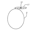
切除前のECG信号を取得して記録すると、切除部品22を第1の組織部位S1に接触するよう設置する(図16D)。これは、マッピングが完了した後に所定の位置に曲線C1を留めるか、又は頂部A1を中心として開口Oの中で曲線C1を回転させて切除部品22を直近のマッピング処理が実行されたのとは異なる組織部位に接触するよう設置することで、容易に行われる。そして、RF発生器18(図1参照)が作動して、(単極又は双極モードで)切除部品22にRFエネルギを伝え、これにより線状の損傷を形成する(図16E)。図に示すように、線状の損傷L1は、開口Oの周に対して接線方向にあり、これにより、肺静脈PVから離れる方に向いた電気的経路を遮断した状態で、開口Oの周りの損傷L1の間隔及び損傷L1の効果を最大限にする。代替的に、線状の損傷L1が開口Oの周に対して多少斜めになっていてもよいが、開口Oの接線に対して30°以上逸れていないのが好ましい。
When the ECG signal before excision is acquired and recorded, the
次に、曲線C1を頂部A1を中心として開口Oの中で再び回転させて、切除部品22が第2の組織部位S2に接触するよう設置する(図16F)。そして、RF発生器18が作動して切除部品22にRFエネルギを伝え、これにより別の線状の損傷L2を形成する(図16G)。図示するように、線状の損傷L1と同じように、線状の損傷L2は、開口Oの周に対して接線方向にあり、このため、肺静脈PVから離れる方に向いた電気的経路を遮断した状態で、開口Oの周りの損傷L2の間隔及び損傷L2の効果を最大限にする。図示された方法では、第2の組織部位S1の位置は、線状の損傷L1及びL2が連続的な損傷を形成するよう選択される。このような切除プロセスは、開口O全体が円周形態の損傷で囲まれるまで繰り返される。代替的に、不整脈の原因となる基質の位置が既知の場合、別々の線状の損傷Lを開口Oの周囲の有利な位置に形成するように、組織部位Sを選択可能である。
Next, the curve C1 is rotated again around the top A1 in the opening O, and the
当然のことながら、切除部品22の移動が曲線C1の頂部A1の点を中心とする円に限られるため、開口Oの周囲の損傷Lの形成は、より制御された既定のものである。これは、切除部品22の移動を制限せずに制御するのが難しい上記の「フリーハンド」アプローチとは対照的である。さらに、遠位部材30の独特な構成が、回復不可能な損傷の原因とならないよう切除部品22をPVの中に確実に入れないようになっている。
Of course, the formation of the damage L around the opening O is a more controlled default because the movement of the
損傷を形成した後に、マッピング処理装置16が再び作動して、PVからECG信号を取得及び記録する。これらの切除後のECG信号は、切除前のECG信号と比較され、円周形態の損傷が肺静脈PVの中の不整脈の原因となる基質を心臓HのLAから完全に絶縁しているかどうかが判断される。適切な切除が確認されると、ガイドシース12及び切除/マッピングカテーテル14が患者の体内から取り除かれるか、又は代替的に、別の肺静脈の中に円周形態の損傷を形成するのに使用される。
After creating the damage, the
本発明に係る特定の実施例が図示され記載されているが、当然のことながら、それは本発明を図示の実施例に制限することを意図するものではなく、本発明の精神と範囲から逸脱することなく、様々な変更及び改良がなされることは当業者にとって明らかである。このため、本発明は、特許請求の範囲に規定されている本発明の精神と範囲内に含まれる、代替物、改良物、及び同等物をカバーすることを意図するものである。 While particular embodiments of the present invention have been illustrated and described, it should be understood that it is not intended to limit the invention to the illustrated embodiments and departs from the spirit and scope of the invention. It will be apparent to those skilled in the art that various modifications and improvements can be made. Thus, the present invention is intended to cover alternatives, modifications, and equivalents included within the spirit and scope of the present invention as defined by the claims.
図面は、本発明の図示された実施例の構成及び効果を示しており、同一の部品は共通の符号で参照される。本発明の上記及び他の利点及び目的をどのようにして得るかをより良く理解するために、以上において簡単に記載された本発明のより特別な記載が、添付図面に図示されている特定の実施例を参照して表されている。当然のことながら、これらの図面は、本発明の典型的な実施例のみを表すものであり、それゆえに発明の範囲を制限するものと考えるべきではなく、本発明は添付図面の使用を通して付加的な特殊性及び詳細で記載され説明される。 The drawings illustrate the configuration and effects of the illustrated embodiments of the present invention, and like parts are referred to with like numerals. For a better understanding of how the above and other advantages and objects of the present invention may be obtained, a more particular description of the invention briefly described above is given by way of illustration It is represented with reference to the examples. It will be appreciated that these drawings represent only typical embodiments of the invention and therefore should not be considered as limiting the scope of the invention, and that the invention is not limited to the use of the accompanying drawings. Are described and explained with particularity and details.
Claims (33)
前記遠位区間に担持された少なくとも1の動作部品と、
を具えることを特徴とするカテーテル。An elongate and flexible integral catheter body having a proximal shaft portion with a longitudinal axis and a distal shaft portion having a transition section extending collinearly from the proximal shaft portion , the distal shaft portion includes a proximal section that is configured to operate without applying a force from outside simple curve bending from straight configuration 70 ° or more, an intermediate section which is preformed to form a complex curve, The complex curve has a proximal curve and a distal curve, the proximal curve bending in the opposite direction to the simple curve, and an intermediate section in which the distal curve bends out of the plane of the simple curve; A distal section that is substantially straight or pre-shaped to form a simple curve having a peak on the side radially away from the longitudinal axis of the proximal shaft portion ; ,
At least one moving part carried in the distal section;
A catheter characterized by comprising:
前記遠位区間に担持された少なくとも1の動作部品であって、前記単純曲線の前記頂部を前記血管口に挿入したときに前記血管口の近くの組織にしっかりと接触するよう構成された動作部品と、
を具えることを特徴とするカテーテル。A proximal shaft with a longitudinal axis, a proximal section configured to operate internally to form a simple curve capable of inserting the apex into the opening of the anatomical blood vessel, and a curve that curves in the opposite direction of the simple curve An intermediate section pre-shaped to form a distal section configured to be placed in a non-radial relationship with respect to the vascular opening when the top of the simple curve is inserted into the vascular opening. A slender and flexible integral catheter body having a distal shaft portion;
At least one moving part carried in the distal section, the moving part configured to make firm contact with tissue near the vessel opening when the top of the simple curve is inserted into the vessel opening When,
A catheter characterized by comprising:
Applications Claiming Priority (3)
| Application Number | Priority Date | Filing Date | Title |
|---|---|---|---|
| US10/983,072 US8409191B2 (en) | 2004-11-04 | 2004-11-04 | Preshaped ablation catheter for ablating pulmonary vein ostia within the heart |
| US10/983,072 | 2004-11-04 | ||
| PCT/US2005/039785 WO2006052651A1 (en) | 2004-11-04 | 2005-11-04 | Preshaped ablation catheter for ablating pulmonary vein ostia within the heart |
Publications (2)
| Publication Number | Publication Date |
|---|---|
| JP2008518685A JP2008518685A (en) | 2008-06-05 |
| JP5123665B2 true JP5123665B2 (en) | 2013-01-23 |
Family
ID=35922617
Family Applications (1)
| Application Number | Title | Priority Date | Filing Date |
|---|---|---|---|
| JP2007539338A Expired - Fee Related JP5123665B2 (en) | 2004-11-04 | 2005-11-04 | Pre-shaped ablation catheter for excising the pulmonary vein opening of the heart |
Country Status (6)
| Country | Link |
|---|---|
| US (3) | US8409191B2 (en) |
| EP (1) | EP1807143A1 (en) |
| JP (1) | JP5123665B2 (en) |
| AU (1) | AU2005304983B2 (en) |
| CA (1) | CA2584549A1 (en) |
| WO (1) | WO2006052651A1 (en) |
Families Citing this family (104)
| Publication number | Priority date | Publication date | Assignee | Title |
|---|---|---|---|---|
| US8150519B2 (en) | 2002-04-08 | 2012-04-03 | Ardian, Inc. | Methods and apparatus for bilateral renal neuromodulation |
| US7653438B2 (en) | 2002-04-08 | 2010-01-26 | Ardian, Inc. | Methods and apparatus for renal neuromodulation |
| US8774913B2 (en) | 2002-04-08 | 2014-07-08 | Medtronic Ardian Luxembourg S.A.R.L. | Methods and apparatus for intravasculary-induced neuromodulation |
| US8409191B2 (en) | 2004-11-04 | 2013-04-02 | Boston Scientific Scimed, Inc. | Preshaped ablation catheter for ablating pulmonary vein ostia within the heart |
| US8617152B2 (en) | 2004-11-15 | 2013-12-31 | Medtronic Ablation Frontiers Llc | Ablation system with feedback |
| US7429261B2 (en) | 2004-11-24 | 2008-09-30 | Ablation Frontiers, Inc. | Atrial ablation catheter and method of use |
| US7468062B2 (en) | 2004-11-24 | 2008-12-23 | Ablation Frontiers, Inc. | Atrial ablation catheter adapted for treatment of septal wall arrhythmogenic foci and method of use |
| US9320564B2 (en) | 2005-05-05 | 2016-04-26 | Boston Scientific Scimed Inc. | Steerable catheter and method for performing medical procedure adjacent pulmonary vein ostia |
| CN101309651B (en) | 2005-06-20 | 2011-12-07 | 麦德托尼克消融前沿有限公司 | Ablation catheter |
| CA2615267A1 (en) | 2005-07-11 | 2007-01-18 | Ablation Frontiers, Inc. | Low power tissue ablation system |
| US8657814B2 (en) | 2005-08-22 | 2014-02-25 | Medtronic Ablation Frontiers Llc | User interface for tissue ablation system |
| US7623899B2 (en) * | 2005-09-16 | 2009-11-24 | Biosense Webster, Inc. | Catheter with flexible pre-shaped tip section |
| US20070156114A1 (en) * | 2005-12-29 | 2007-07-05 | Worley Seth J | Deflectable catheter with a flexibly attached tip section |
| CN101384212A (en) * | 2006-01-19 | 2009-03-11 | 通用医疗公司 | Method and system for optical imaging of epithelial luminal organs by beam scanning thereof |
| GB0605793D0 (en) * | 2006-03-23 | 2006-05-03 | Depuy Orthopaedie Gmbh | A sensor assembly |
| WO2007120505A1 (en) * | 2006-03-31 | 2007-10-25 | C. R. Bard, Inc. | Catheter including arcuate transition region |
| US8641704B2 (en) | 2007-05-11 | 2014-02-04 | Medtronic Ablation Frontiers Llc | Ablation therapy system and method for treating continuous atrial fibrillation |
| ITBA20070049A1 (en) * | 2007-06-14 | 2008-12-15 | Massimo Grimaldi | CATHETERS FOR ABLATION TRANSCATETER BY PERCUTANEOUS ROUTE OF HEART ARITHMIA THROUGH BIPOLAR RADIOFREQUENCY |
| US9125562B2 (en) | 2009-07-01 | 2015-09-08 | Avinger, Inc. | Catheter-based off-axis optical coherence tomography imaging system |
| WO2010039443A1 (en) * | 2008-10-04 | 2010-04-08 | Boston Scientific Scimed, Inc. | Loop structures for supporting diagnostic and/or therapeutic elements in contact with tissue |
| US8652129B2 (en) | 2008-12-31 | 2014-02-18 | Medtronic Ardian Luxembourg S.A.R.L. | Apparatus, systems, and methods for achieving intravascular, thermally-induced renal neuromodulation |
| EP2398543A1 (en) | 2009-02-20 | 2011-12-28 | Boston Scientific Scimed, Inc. | Asymmetric dual directional steerable catheter sheath |
| WO2010129075A1 (en) | 2009-04-28 | 2010-11-11 | Avinger, Inc. | Guidewire support catheter |
| US9393068B1 (en) | 2009-05-08 | 2016-07-19 | St. Jude Medical International Holding S.À R.L. | Method for predicting the probability of steam pop in RF ablation therapy |
| CN104605928B (en) | 2009-05-08 | 2018-01-05 | 圣犹达医疗用品国际控股有限公司 | System for controlling lesion size in catheter-based ablation therapy |
| WO2010138927A2 (en) | 2009-05-28 | 2010-12-02 | Avinger, Inc. | Optical coherence tomography for biological imaging |
| WO2011003006A2 (en) | 2009-07-01 | 2011-01-06 | Avinger, Inc. | Atherectomy catheter with laterally-displaceable tip |
| US8870863B2 (en) | 2010-04-26 | 2014-10-28 | Medtronic Ardian Luxembourg S.A.R.L. | Catheter apparatuses, systems, and methods for renal neuromodulation |
| US11382653B2 (en) | 2010-07-01 | 2022-07-12 | Avinger, Inc. | Atherectomy catheter |
| US8794830B2 (en) * | 2010-10-13 | 2014-08-05 | Biosense Webster, Inc. | Catheter with digitized temperature measurement in control handle |
| US9089350B2 (en) * | 2010-11-16 | 2015-07-28 | Boston Scientific Scimed, Inc. | Renal denervation catheter with RF electrode and integral contrast dye injection arrangement |
| JP6027024B2 (en) | 2010-12-27 | 2016-11-16 | セント・ジュード・メディカル・ルクセンブルク・ホールディング・エスエーアールエル | Prediction of atrial wall electrical reconnection based on contact force measured during RF ablation |
| JP5557393B2 (en) * | 2011-01-19 | 2014-07-23 | 日本ライフライン株式会社 | Tip deflectable catheter |
| US9949754B2 (en) | 2011-03-28 | 2018-04-24 | Avinger, Inc. | Occlusion-crossing devices |
| EP2691038B1 (en) | 2011-03-28 | 2016-07-20 | Avinger, Inc. | Occlusion-crossing devices, imaging, and atherectomy devices |
| US9345406B2 (en) | 2011-11-11 | 2016-05-24 | Avinger, Inc. | Occlusion-crossing devices, atherectomy devices, and imaging |
| WO2013172972A1 (en) | 2012-05-14 | 2013-11-21 | Avinger, Inc. | Optical coherence tomography with graded index fiber for biological imaging |
| WO2013172974A1 (en) | 2012-05-14 | 2013-11-21 | Avinger, Inc. | Atherectomy catheter drive assemblies |
| JP6301926B2 (en) | 2012-08-09 | 2018-03-28 | ユニバーシティ オブ アイオワ リサーチ ファウンデーション | Catheter, catheter system, and method for piercing tissue structure |
| US10252023B2 (en) | 2013-01-11 | 2019-04-09 | C. R. Bard, Inc. | Curved catheter and methods for making same |
| US9179971B2 (en) | 2013-02-11 | 2015-11-10 | St. Jude Medical, Atrial Fibrillation Division, Inc. | Printed electrode catheter |
| WO2014143064A1 (en) | 2013-03-15 | 2014-09-18 | Avinger, Inc. | Chronic total occlusion crossing devices with imaging |
| US11096717B2 (en) | 2013-03-15 | 2021-08-24 | Avinger, Inc. | Tissue collection device for catheter |
| US10932670B2 (en) | 2013-03-15 | 2021-03-02 | Avinger, Inc. | Optical pressure sensor assembly |
| JP6517198B2 (en) | 2013-07-08 | 2019-05-22 | アビンガー・インコーポレイテッドAvinger, Inc. | Identification of elastic layers guiding interventions |
| CN110833455B (en) * | 2013-10-25 | 2023-02-28 | 直观外科手术操作公司 | Flexible Instruments with Embedded Actuation Catheters |
| WO2015103574A1 (en) | 2014-01-06 | 2015-07-09 | Iowa Approach Inc. | Apparatus and methods for renal denervation ablation |
| CN105939662B (en) | 2014-01-28 | 2019-02-15 | 圣犹达医疗用品国际控股有限公司 | Medical device with encapsulated electronic assembly and method of making the same |
| US11116449B2 (en) | 2014-01-28 | 2021-09-14 | St. Jude Medical, Cardiology Division, Inc. | Catheter shaft with electrically-conductive traces |
| US9730755B2 (en) | 2014-01-31 | 2017-08-15 | Medtronic Cryocath Lp | Medical device with adjustable flexibility |
| EP4670627A3 (en) | 2014-05-07 | 2026-03-25 | Boston Scientific Scimed, Inc. | Methods and apparatus for selective tissue ablation |
| WO2015175944A1 (en) | 2014-05-16 | 2015-11-19 | Gary Long | Methods and apparatus for multi-catheter tissue ablation |
| CN105078569B (en) * | 2014-05-22 | 2017-11-10 | 南京医科大学第一附属医院 | Sympathetic nerve mapping ablating device and system |
| EP3154463B1 (en) | 2014-06-12 | 2019-03-27 | Farapulse, Inc. | Apparatus for rapid and selective transurethral tissue ablation |
| WO2015192018A1 (en) | 2014-06-12 | 2015-12-17 | Iowa Approach Inc. | Method and apparatus for rapid and selective tissue ablation with cooling |
| MX2017000303A (en) | 2014-07-08 | 2017-07-10 | Avinger Inc | High speed chronic total occlusion crossing devices. |
| EP3206613B1 (en) | 2014-10-14 | 2019-07-03 | Farapulse, Inc. | Apparatus for rapid and safe pulmonary vein cardiac ablation |
| WO2016081611A1 (en) | 2014-11-19 | 2016-05-26 | Advanced Cardiac Therapeutics, Inc. | High-resolution mapping of tissue with pacing |
| WO2016081650A1 (en) | 2014-11-19 | 2016-05-26 | Advanced Cardiac Therapeutics, Inc. | Ablation devices, systems and methods of using a high-resolution electrode assembly |
| EP3220844B1 (en) | 2014-11-19 | 2020-11-11 | EPiX Therapeutics, Inc. | Systems for high-resolution mapping of tissue |
| US9636164B2 (en) | 2015-03-25 | 2017-05-02 | Advanced Cardiac Therapeutics, Inc. | Contact sensing systems and methods |
| EP3322338B1 (en) | 2015-07-13 | 2025-02-12 | Avinger, Inc. | Micro-molded anamorphic reflector lens for image guided therapeutic/diagnostic catheters |
| US11007007B2 (en) * | 2015-10-13 | 2021-05-18 | Biosense Webster (Israel) Ltd. | Self-centering multiray ablation catheter |
| US10660702B2 (en) | 2016-01-05 | 2020-05-26 | Farapulse, Inc. | Systems, devices, and methods for focal ablation |
| US20170189097A1 (en) | 2016-01-05 | 2017-07-06 | Iowa Approach Inc. | Systems, apparatuses and methods for delivery of ablative energy to tissue |
| US10172673B2 (en) | 2016-01-05 | 2019-01-08 | Farapulse, Inc. | Systems devices, and methods for delivery of pulsed electric field ablative energy to endocardial tissue |
| US10130423B1 (en) | 2017-07-06 | 2018-11-20 | Farapulse, Inc. | Systems, devices, and methods for focal ablation |
| US12144541B2 (en) | 2016-01-05 | 2024-11-19 | Boston Scientific Scimed, Inc. | Systems, apparatuses and methods for delivery of ablative energy to tissue |
| CN108882857A (en) | 2016-01-25 | 2018-11-23 | 阿维格公司 | With the modified OCT image conduit of lag |
| SG11201807618QA (en) | 2016-03-15 | 2018-10-30 | Epix Therapeutics Inc | Improved devices, systems and methods for irrigated ablation |
| JP6959255B2 (en) | 2016-04-01 | 2021-11-02 | アビンガー・インコーポレイテッドAvinger, Inc. | Catheter device for porridge resection |
| US11344327B2 (en) | 2016-06-03 | 2022-05-31 | Avinger, Inc. | Catheter device with detachable distal end |
| EP3471631A4 (en) | 2016-06-16 | 2020-03-04 | Farapulse, Inc. | GUIDE WIRE DISTRIBUTION SYSTEMS, APPARATUSES AND METHODS |
| US11224459B2 (en) * | 2016-06-30 | 2022-01-18 | Avinger, Inc. | Atherectomy catheter with shapeable distal tip |
| US10398892B2 (en) * | 2016-07-21 | 2019-09-03 | Medtronic, Inc. | Interventional medical systems and associated assemblies and methods |
| EP3544549A4 (en) | 2016-11-22 | 2020-08-12 | Synecor LLC | WIRELESS GUIDED TRANSSEPTAL RELEASE SYSTEM FOR THERAPEUTIC DEVICES OF THE MITRAL VALVE |
| EP3614946B1 (en) | 2017-04-27 | 2024-03-20 | EPiX Therapeutics, Inc. | Determining nature of contact between catheter tip and tissue |
| US9987081B1 (en) | 2017-04-27 | 2018-06-05 | Iowa Approach, Inc. | Systems, devices, and methods for signal generation |
| US10617867B2 (en) | 2017-04-28 | 2020-04-14 | Farapulse, Inc. | Systems, devices, and methods for delivery of pulsed electric field ablative energy to esophageal tissue |
| JP2018201575A (en) * | 2017-05-30 | 2018-12-27 | 株式会社カネカ | Catheter and manufacturing method thereof |
| WO2019055154A2 (en) | 2017-08-06 | 2019-03-21 | Synecor Llc | Systems and methods for transseptal delivery of therapeutic devices of the heart |
| CN115844523A (en) | 2017-09-12 | 2023-03-28 | 波士顿科学医学有限公司 | Systems, devices, and methods for ventricular focal ablation |
| EP3749238B1 (en) | 2018-02-08 | 2023-08-16 | Farapulse, Inc. | Apparatus for controlled delivery of pulsed electric field ablative energy to tissue |
| US11471190B2 (en) * | 2018-04-02 | 2022-10-18 | Cardiac Pacemakers, Inc. | Bundle of his lead delivery catheter, system and method |
| US12167867B2 (en) | 2018-04-19 | 2024-12-17 | Avinger, Inc. | Occlusion-crossing devices |
| US20190336198A1 (en) | 2018-05-03 | 2019-11-07 | Farapulse, Inc. | Systems, devices, and methods for ablation using surgical clamps |
| CN115836908A (en) | 2018-05-07 | 2023-03-24 | 波士顿科学医学有限公司 | Systems, devices, and methods for delivering ablation energy to tissue |
| CN116327352A (en) | 2018-05-07 | 2023-06-27 | 波士顿科学医学有限公司 | epicardial ablation catheter |
| EP3790483B1 (en) | 2018-05-07 | 2024-08-28 | Boston Scientific Scimed, Inc. | Systems for filtering high voltage noise induced by pulsed electric field ablation |
| CN112955088B (en) | 2018-09-20 | 2024-11-26 | 波士顿科学医学有限公司 | Systems, devices and methods for delivering pulsed electric field ablation energy to endocardial tissue |
| US11000637B2 (en) | 2019-02-07 | 2021-05-11 | Synecor Llc | Systems and methods for transseptal delivery of percutaneous ventricular assist devices and other non-guidewire based transvascular therapeutic devices |
| WO2020166226A1 (en) * | 2019-02-12 | 2020-08-20 | テルモ株式会社 | Catheter, housing tool, and assembly |
| US10625080B1 (en) | 2019-09-17 | 2020-04-21 | Farapulse, Inc. | Systems, apparatuses, and methods for detecting ectopic electrocardiogram signals during pulsed electric field ablation |
| US11471650B2 (en) | 2019-09-20 | 2022-10-18 | Biosense Webster (Israel) Ltd. | Mechanism for manipulating a puller wire |
| JP2022553223A (en) | 2019-10-18 | 2022-12-22 | アビンガー・インコーポレイテッド | occlusion crossing device |
| US11065047B2 (en) | 2019-11-20 | 2021-07-20 | Farapulse, Inc. | Systems, apparatuses, and methods for protecting electronic components from high power noise induced by high voltage pulses |
| US11497541B2 (en) | 2019-11-20 | 2022-11-15 | Boston Scientific Scimed, Inc. | Systems, apparatuses, and methods for protecting electronic components from high power noise induced by high voltage pulses |
| US10842572B1 (en) | 2019-11-25 | 2020-11-24 | Farapulse, Inc. | Methods, systems, and apparatuses for tracking ablation devices and generating lesion lines |
| US12256906B2 (en) * | 2020-01-28 | 2025-03-25 | Gyrus Acmi, Inc. | Medical devices with biliary diagnostic devices |
| JP7536995B2 (en) | 2020-07-24 | 2024-08-20 | ボストン サイエンティフィック サイムド,インコーポレイテッド | Electric field application for single-shot cardiac ablation by irreversible electroporation |
| US12310652B2 (en) | 2020-07-24 | 2025-05-27 | Boston Scientific Scimed, Inc. | Hybrid electroporation ablation catheter |
| US12496123B2 (en) | 2020-09-08 | 2025-12-16 | Boston Scientific Scimed, Inc. | Contoured electrodes for pulsed electric field ablation, and systems, devices, and methods thereof |
| WO2022072385A2 (en) | 2020-09-30 | 2022-04-07 | Boston Scientific Scimed Inc | Pretreatment waveform for irreversible electroporation |
| EP4284276A1 (en) | 2021-01-27 | 2023-12-06 | Boston Scientific Scimed, Inc. | Voltage controlled pulse sequences for irreversible electroporation ablations |
Family Cites Families (103)
| Publication number | Priority date | Publication date | Assignee | Title |
|---|---|---|---|---|
| US30729A (en) * | 1860-11-27 | Improvement in cotton-plows | ||
| US865331A (en) * | 1907-02-20 | 1907-09-03 | William H Coldwell | Lawn-mower. |
| US949408A (en) * | 1908-06-25 | 1910-02-15 | John T Henderson | Knot-tying machine. |
| US4706671A (en) * | 1985-05-02 | 1987-11-17 | Weinrib Harry P | Catheter with coiled tip |
| US4650466A (en) * | 1985-11-01 | 1987-03-17 | Angiobrade Partners | Angioplasty device |
| US4882777A (en) * | 1987-04-17 | 1989-11-21 | Narula Onkar S | Catheter |
| US4921484A (en) * | 1988-07-25 | 1990-05-01 | Cordis Corporation | Mesh balloon catheter device |
| US5820591A (en) * | 1990-02-02 | 1998-10-13 | E. P. Technologies, Inc. | Assemblies for creating compound curves in distal catheter regions |
| US5156151A (en) * | 1991-02-15 | 1992-10-20 | Cardiac Pathways Corporation | Endocardial mapping and ablation system and catheter probe |
| US5228442A (en) * | 1991-02-15 | 1993-07-20 | Cardiac Pathways Corporation | Method for mapping, ablation, and stimulation using an endocardial catheter |
| US6029671A (en) * | 1991-07-16 | 2000-02-29 | Heartport, Inc. | System and methods for performing endovascular procedures |
| US5584803A (en) * | 1991-07-16 | 1996-12-17 | Heartport, Inc. | System for cardiac procedures |
| US5327885A (en) * | 1991-10-08 | 1994-07-12 | Griffith James M | Combination catheter for invasive probe delivery and balloon dilation |
| DE69233091T2 (en) * | 1991-11-08 | 2004-05-06 | Boston Scientific Ltd., St. Michael | ABLATION ELECTRODE WITH INSULATED TEMPERATURE MEASURING ELEMENT |
| US5383874A (en) * | 1991-11-08 | 1995-01-24 | Ep Technologies, Inc. | Systems for identifying catheters and monitoring their use |
| US5327905A (en) | 1992-02-14 | 1994-07-12 | Boaz Avitall | Biplanar deflectable catheter for arrhythmogenic tissue ablation |
| US5263493A (en) * | 1992-02-24 | 1993-11-23 | Boaz Avitall | Deflectable loop electrode array mapping and ablation catheter for cardiac chambers |
| US5239999A (en) * | 1992-03-27 | 1993-08-31 | Cardiac Pathways Corporation | Helical endocardial catheter probe |
| JP2636504B2 (en) * | 1992-07-27 | 1997-07-30 | シュナイダー・(ユーエスエイ)・インコーポレーテッド | Dilatation catheter with injection lumen |
| SE9203733D0 (en) * | 1992-12-11 | 1992-12-11 | Siemens Elema Ab | defibrillation |
| US5456667A (en) * | 1993-05-20 | 1995-10-10 | Advanced Cardiovascular Systems, Inc. | Temporary stenting catheter with one-piece expandable segment |
| US5391199A (en) * | 1993-07-20 | 1995-02-21 | Biosense, Inc. | Apparatus and method for treating cardiac arrhythmias |
| US5423772A (en) * | 1993-08-13 | 1995-06-13 | Daig Corporation | Coronary sinus catheter |
| DE69435281D1 (en) | 1993-09-17 | 2010-04-22 | Edwards Lifesciences Ag | Endovascular system for creating an artificial cardiac arrest |
| US5582609A (en) * | 1993-10-14 | 1996-12-10 | Ep Technologies, Inc. | Systems and methods for forming large lesions in body tissue using curvilinear electrode elements |
| WO1995010318A1 (en) * | 1993-10-14 | 1995-04-20 | Ep Technologies, Inc. | Electrode elements for forming lesion patterns |
| US5991650A (en) * | 1993-10-15 | 1999-11-23 | Ep Technologies, Inc. | Surface coatings for catheters, direct contacting diagnostic and therapeutic devices |
| US5575766A (en) | 1993-11-03 | 1996-11-19 | Daig Corporation | Process for the nonsurgical mapping and treatment of atrial arrhythmia using catheters guided by shaped guiding introducers |
| EP0728029B1 (en) * | 1993-11-10 | 1999-06-16 | Medtronic Cardiorhythm | Electrode array catheter |
| US5617854A (en) * | 1994-06-22 | 1997-04-08 | Munsif; Anand | Shaped catheter device and method |
| US5505730A (en) * | 1994-06-24 | 1996-04-09 | Stuart D. Edwards | Thin layer ablation apparatus |
| WO1996000528A1 (en) * | 1994-06-27 | 1996-01-11 | Ep Technologies, Inc. | Non-linear control systems and methods for heating and ablating body tissue |
| DE4425195C1 (en) * | 1994-07-16 | 1995-11-16 | Osypka Peter | Heart catheter with multiple electrode device |
| US6464700B1 (en) * | 1994-10-07 | 2002-10-15 | Scimed Life Systems, Inc. | Loop structures for positioning a diagnostic or therapeutic element on the epicardium or other organ surface |
| US5885278A (en) * | 1994-10-07 | 1999-03-23 | E.P. Technologies, Inc. | Structures for deploying movable electrode elements |
| WO1996034646A1 (en) * | 1995-05-01 | 1996-11-07 | Medtronic Cardiorhythm | Dual curve ablation catheter and method |
| US6002956A (en) * | 1995-05-23 | 1999-12-14 | Cardima, Inc. | Method of treating using an over-the-wire EP catheter |
| US5571038A (en) * | 1995-08-15 | 1996-11-05 | Halling; Richard | Model airplane flight simulator |
| US5733280A (en) * | 1995-11-15 | 1998-03-31 | Avitall; Boaz | Cryogenic epicardial mapping and ablation |
| US5823955A (en) * | 1995-11-20 | 1998-10-20 | Medtronic Cardiorhythm | Atrioventricular valve tissue ablation catheter and method |
| US5697377A (en) * | 1995-11-22 | 1997-12-16 | Medtronic, Inc. | Catheter mapping system and method |
| DE898480T1 (en) | 1996-01-19 | 1999-10-07 | Scimed Life Systems, Inc. | CATHETER WITH A CURVE WITH INCREASING RADIUS |
| US5755760A (en) * | 1996-03-11 | 1998-05-26 | Medtronic, Inc. | Deflectable catheter |
| US5882346A (en) * | 1996-07-15 | 1999-03-16 | Cardiac Pathways Corporation | Shapable catheter using exchangeable core and method of use |
| US5972019A (en) * | 1996-07-25 | 1999-10-26 | Target Therapeutics, Inc. | Mechanical clot treatment device |
| US6311692B1 (en) * | 1996-10-22 | 2001-11-06 | Epicor, Inc. | Apparatus and method for diagnosis and therapy of electrophysiological disease |
| US6237605B1 (en) * | 1996-10-22 | 2001-05-29 | Epicor, Inc. | Methods of epicardial ablation |
| US6096036A (en) * | 1998-05-05 | 2000-08-01 | Cardiac Pacemakers, Inc. | Steerable catheter with preformed distal shape and method for use |
| US6002955A (en) * | 1996-11-08 | 1999-12-14 | Medtronic, Inc. | Stabilized electrophysiology catheter and method for use |
| US6071279A (en) * | 1996-12-19 | 2000-06-06 | Ep Technologies, Inc. | Branched structures for supporting multiple electrode elements |
| US5916213A (en) * | 1997-02-04 | 1999-06-29 | Medtronic, Inc. | Systems and methods for tissue mapping and ablation |
| US6024740A (en) * | 1997-07-08 | 2000-02-15 | The Regents Of The University Of California | Circumferential ablation device assembly |
| US5971983A (en) * | 1997-05-09 | 1999-10-26 | The Regents Of The University Of California | Tissue ablation device and method of use |
| US6012457A (en) * | 1997-07-08 | 2000-01-11 | The Regents Of The University Of California | Device and method for forming a circumferential conduction block in a pulmonary vein |
| US5938660A (en) * | 1997-06-27 | 1999-08-17 | Daig Corporation | Process and device for the treatment of atrial arrhythmia |
| US6164283A (en) * | 1997-07-08 | 2000-12-26 | The Regents Of The University Of California | Device and method for forming a circumferential conduction block in a pulmonary vein |
| US6652515B1 (en) * | 1997-07-08 | 2003-11-25 | Atrionix, Inc. | Tissue ablation device assembly and method for electrically isolating a pulmonary vein ostium from an atrial wall |
| AU8507698A (en) * | 1997-07-29 | 1999-02-22 | Ep Technologies Inc | Improved catheter distal end assemblies |
| US6490474B1 (en) * | 1997-08-01 | 2002-12-03 | Cardiac Pathways Corporation | System and method for electrode localization using ultrasound |
| US6066126A (en) * | 1997-12-18 | 2000-05-23 | Medtronic, Inc. | Precurved, dual curve cardiac introducer sheath |
| US6064902A (en) * | 1998-04-16 | 2000-05-16 | C.R. Bard, Inc. | Pulmonary vein ablation catheter |
| US6592581B2 (en) * | 1998-05-05 | 2003-07-15 | Cardiac Pacemakers, Inc. | Preformed steerable catheter with movable outer sleeve and method for use |
| US6950689B1 (en) * | 1998-08-03 | 2005-09-27 | Boston Scientific Scimed, Inc. | Dynamically alterable three-dimensional graphical model of a body region |
| US6090474A (en) * | 1998-09-01 | 2000-07-18 | International Business Machines Corporation | Flowable compositions and use in filling vias and plated through-holes |
| US6572611B1 (en) * | 1998-11-23 | 2003-06-03 | C. R. Bard, Inc. | Intracardiac grasp catheter |
| DE69941155D1 (en) | 1998-11-23 | 2009-09-03 | Bard Inc C R | ENDOCARDIAL CATHETER |
| US6325797B1 (en) * | 1999-04-05 | 2001-12-04 | Medtronic, Inc. | Ablation catheter and method for isolating a pulmonary vein |
| US20010007070A1 (en) * | 1999-04-05 | 2001-07-05 | Medtronic, Inc. | Ablation catheter assembly and method for isolating a pulmonary vein |
| US6783510B1 (en) * | 1999-07-08 | 2004-08-31 | C.R. Bard, Inc. | Steerable catheter |
| US7935108B2 (en) | 1999-07-14 | 2011-05-03 | Cardiofocus, Inc. | Deflectable sheath catheters |
| US6485489B2 (en) * | 1999-10-02 | 2002-11-26 | Quantum Cor, Inc. | Catheter system for repairing a mitral valve annulus |
| US20030069570A1 (en) * | 1999-10-02 | 2003-04-10 | Witzel Thomas H. | Methods for repairing mitral valve annulus percutaneously |
| US6224587B1 (en) * | 1999-11-22 | 2001-05-01 | C.R. Bard, Inc. | Steerable catheter |
| US6645199B1 (en) * | 1999-11-22 | 2003-11-11 | Scimed Life Systems, Inc. | Loop structures for supporting diagnostic and therapeutic elements contact with body tissue and expandable push devices for use with same |
| US6542781B1 (en) * | 1999-11-22 | 2003-04-01 | Scimed Life Systems, Inc. | Loop structures for supporting diagnostic and therapeutic elements in contact with body tissue |
| US6529756B1 (en) * | 1999-11-22 | 2003-03-04 | Scimed Life Systems, Inc. | Apparatus for mapping and coagulating soft tissue in or around body orifices |
| US6745080B2 (en) * | 1999-11-22 | 2004-06-01 | Scimed Life Systems, Inc. | Helical and pre-oriented loop structures for supporting diagnostic and therapeutic elements in contact with body tissue |
| US6628976B1 (en) * | 2000-01-27 | 2003-09-30 | Biosense Webster, Inc. | Catheter having mapping assembly |
| DE60134739D1 (en) | 2000-05-16 | 2008-08-21 | Atrionix Inc | CATHETER WITH STEERING TIP AND TRACKING MECHANISM OF A GUIDE WIRE |
| US6926669B1 (en) * | 2000-10-10 | 2005-08-09 | Medtronic, Inc. | Heart wall ablation/mapping catheter and method |
| US6728563B2 (en) * | 2000-11-29 | 2004-04-27 | St. Jude Medical, Daig Division, Inc. | Electrophysiology/ablation catheter having “halo” configuration |
| US7785323B2 (en) * | 2000-12-04 | 2010-08-31 | Boston Scientific Scimed, Inc. | Loop structure including inflatable therapeutic device |
| WO2002087676A2 (en) * | 2001-04-27 | 2002-11-07 | C.R. Bard, Inc. | Electrophysiology catheter for mapping and/or ablation |
| US6669693B2 (en) * | 2001-11-13 | 2003-12-30 | Mayo Foundation For Medical Education And Research | Tissue ablation device and methods of using |
| US7493156B2 (en) * | 2002-01-07 | 2009-02-17 | Cardiac Pacemakers, Inc. | Steerable guide catheter with pre-shaped rotatable shaft |
| US6926714B1 (en) * | 2002-02-05 | 2005-08-09 | Jasbir S. Sra | Method for pulmonary vein isolation and catheter ablation of other structures in the left atrium in atrial fibrillation |
| US6733499B2 (en) * | 2002-02-28 | 2004-05-11 | Biosense Webster, Inc. | Catheter having circular ablation assembly |
| US6869414B2 (en) * | 2002-03-22 | 2005-03-22 | Cardiac Pacemakers, Inc. | Pre-shaped catheter with proximal articulation and pre-formed distal end |
| US6887236B2 (en) * | 2002-05-03 | 2005-05-03 | Pinhas Gilboa | Multiple-electrode catheter assembly and method of operating such a catheter assembly |
| US20040034365A1 (en) * | 2002-08-16 | 2004-02-19 | Lentz David J. | Catheter having articulation system |
| EP1539291A4 (en) | 2002-09-20 | 2010-03-10 | Flowmedica Inc | Method and apparatus for selective material delivery via an intra-renal catheter |
| JP5328074B2 (en) * | 2002-10-31 | 2013-10-30 | シー・アール・バード・インコーポレーテッド | Improved electrophysiology catheter |
| US7013169B2 (en) * | 2003-01-27 | 2006-03-14 | Cardiac Pacemakers, Inc. | Dual steer preshaped catheter |
| US6923808B2 (en) * | 2003-02-24 | 2005-08-02 | Boston Scientific Scimed, Inc. | Probes having helical and loop shaped inflatable therapeutic elements |
| US7101362B2 (en) * | 2003-07-02 | 2006-09-05 | St. Jude Medical, Atrial Fibrillation Division, Inc. | Steerable and shapable catheter employing fluid force |
| US6973339B2 (en) | 2003-07-29 | 2005-12-06 | Biosense, Inc | Lasso for pulmonary vein mapping and ablation |
| US7435248B2 (en) * | 2003-09-26 | 2008-10-14 | Boston Scientific Scimed, Inc. | Medical probes for creating and diagnosing circumferential lesions within or around the ostium of a vessel |
| US20050197623A1 (en) | 2004-02-17 | 2005-09-08 | Leeflang Stephen A. | Variable steerable catheters and methods for using them |
| US7245955B2 (en) * | 2004-02-23 | 2007-07-17 | St. Jude Medical, Atrial Fibrillation Division, Inc. | Electrophysiology/ablation catheter having deflection assembly |
| US7013619B2 (en) | 2004-06-07 | 2006-03-21 | Clearwater Packaging, Inc. | Property and evidence preservation system |
| EP1781363B1 (en) | 2004-08-05 | 2019-06-05 | Cathrx Ltd | A steerable catheter |
| US8409191B2 (en) | 2004-11-04 | 2013-04-02 | Boston Scientific Scimed, Inc. | Preshaped ablation catheter for ablating pulmonary vein ostia within the heart |
| US8377050B2 (en) | 2007-06-08 | 2013-02-19 | Boston Scientific Scimed, Inc. | Cryo-applicator cross-section configuration |
-
2004
- 2004-11-04 US US10/983,072 patent/US8409191B2/en not_active Expired - Fee Related
-
2005
- 2005-11-04 JP JP2007539338A patent/JP5123665B2/en not_active Expired - Fee Related
- 2005-11-04 EP EP05824866A patent/EP1807143A1/en not_active Withdrawn
- 2005-11-04 CA CA002584549A patent/CA2584549A1/en not_active Abandoned
- 2005-11-04 WO PCT/US2005/039785 patent/WO2006052651A1/en not_active Ceased
- 2005-11-04 AU AU2005304983A patent/AU2005304983B2/en not_active Ceased
-
2013
- 2013-03-15 US US13/833,046 patent/US9186481B2/en not_active Expired - Fee Related
-
2015
- 2015-11-16 US US14/942,906 patent/US20160066993A1/en not_active Abandoned
Also Published As
| Publication number | Publication date |
|---|---|
| JP2008518685A (en) | 2008-06-05 |
| US20160066993A1 (en) | 2016-03-10 |
| US8409191B2 (en) | 2013-04-02 |
| US9186481B2 (en) | 2015-11-17 |
| US20130184549A1 (en) | 2013-07-18 |
| CA2584549A1 (en) | 2006-05-18 |
| AU2005304983B2 (en) | 2011-09-08 |
| EP1807143A1 (en) | 2007-07-18 |
| AU2005304983A1 (en) | 2006-05-18 |
| US20060095030A1 (en) | 2006-05-04 |
| WO2006052651A1 (en) | 2006-05-18 |
Similar Documents
| Publication | Publication Date | Title |
|---|---|---|
| JP5123665B2 (en) | Pre-shaped ablation catheter for excising the pulmonary vein opening of the heart | |
| JP5188389B2 (en) | Pre-shaped localization catheter and system for reconstructing the pulmonary vein port as an image | |
| EP2364118B1 (en) | Loop structures for supporting diagnostic and/or therapeutic elements in contact with tissue | |
| JP5090737B2 (en) | A probe assembly that forms a circumferential lesion in or around the vascular mouth | |
| IL277699B1 (en) | Intraluminal reference electrode for cardiovascular treatment apparatus | |
| EP1331893A2 (en) | Steerable loop structures for supporting diagnostic and therapeutic elements in contact with body tissue | |
| JP2002531165A (en) | Internal mechanism for moving slidable electrodes | |
| US12089891B2 (en) | Multi-use endocardial ablation catheter |
Legal Events
| Date | Code | Title | Description |
|---|---|---|---|
| A621 | Written request for application examination |
Free format text: JAPANESE INTERMEDIATE CODE: A621 Effective date: 20081029 |
|
| A521 | Request for written amendment filed |
Free format text: JAPANESE INTERMEDIATE CODE: A821 Effective date: 20090109 |
|
| RD02 | Notification of acceptance of power of attorney |
Free format text: JAPANESE INTERMEDIATE CODE: A7422 Effective date: 20090109 |
|
| RD04 | Notification of resignation of power of attorney |
Free format text: JAPANESE INTERMEDIATE CODE: A7424 Effective date: 20090121 |
|
| A977 | Report on retrieval |
Free format text: JAPANESE INTERMEDIATE CODE: A971007 Effective date: 20110620 |
|
| A131 | Notification of reasons for refusal |
Free format text: JAPANESE INTERMEDIATE CODE: A131 Effective date: 20110622 |
|
| A02 | Decision of refusal |
Free format text: JAPANESE INTERMEDIATE CODE: A02 Effective date: 20111028 |
|
| A521 | Request for written amendment filed |
Free format text: JAPANESE INTERMEDIATE CODE: A523 Effective date: 20120227 |
|
| A911 | Transfer to examiner for re-examination before appeal (zenchi) |
Free format text: JAPANESE INTERMEDIATE CODE: A911 Effective date: 20120305 |
|
| A131 | Notification of reasons for refusal |
Free format text: JAPANESE INTERMEDIATE CODE: A131 Effective date: 20120514 |
|
| A521 | Request for written amendment filed |
Free format text: JAPANESE INTERMEDIATE CODE: A523 Effective date: 20120813 |
|
| TRDD | Decision of grant or rejection written | ||
| A01 | Written decision to grant a patent or to grant a registration (utility model) |
Free format text: JAPANESE INTERMEDIATE CODE: A01 Effective date: 20120928 |
|
| A01 | Written decision to grant a patent or to grant a registration (utility model) |
Free format text: JAPANESE INTERMEDIATE CODE: A01 |
|
| A61 | First payment of annual fees (during grant procedure) |
Free format text: JAPANESE INTERMEDIATE CODE: A61 Effective date: 20121026 |
|
| FPAY | Renewal fee payment (event date is renewal date of database) |
Free format text: PAYMENT UNTIL: 20151102 Year of fee payment: 3 |
|
| R150 | Certificate of patent or registration of utility model |
Free format text: JAPANESE INTERMEDIATE CODE: R150 Ref document number: 5123665 Country of ref document: JP Free format text: JAPANESE INTERMEDIATE CODE: R150 |
|
| R250 | Receipt of annual fees |
Free format text: JAPANESE INTERMEDIATE CODE: R250 |
|
| R250 | Receipt of annual fees |
Free format text: JAPANESE INTERMEDIATE CODE: R250 |
|
| R250 | Receipt of annual fees |
Free format text: JAPANESE INTERMEDIATE CODE: R250 |
|
| R250 | Receipt of annual fees |
Free format text: JAPANESE INTERMEDIATE CODE: R250 |
|
| R250 | Receipt of annual fees |
Free format text: JAPANESE INTERMEDIATE CODE: R250 |
|
| LAPS | Cancellation because of no payment of annual fees |