JP5126321B2 - 燃料用フィルタ装置 - Google Patents
燃料用フィルタ装置 Download PDFInfo
- Publication number
- JP5126321B2 JP5126321B2 JP2010193270A JP2010193270A JP5126321B2 JP 5126321 B2 JP5126321 B2 JP 5126321B2 JP 2010193270 A JP2010193270 A JP 2010193270A JP 2010193270 A JP2010193270 A JP 2010193270A JP 5126321 B2 JP5126321 B2 JP 5126321B2
- Authority
- JP
- Japan
- Prior art keywords
- fuel
- filtration layer
- filter
- filtration
- layer
- Prior art date
- Legal status (The legal status is an assumption and is not a legal conclusion. Google has not performed a legal analysis and makes no representation as to the accuracy of the status listed.)
- Active
Links
Images









Classifications
-
- B—PERFORMING OPERATIONS; TRANSPORTING
- B01—PHYSICAL OR CHEMICAL PROCESSES OR APPARATUS IN GENERAL
- B01D—SEPARATION
- B01D29/00—Filters with filtering elements stationary during filtration, e.g. pressure or suction filters, not covered by groups B01D24/00 - B01D27/00; Filtering elements therefor
- B01D29/01—Filters with filtering elements stationary during filtration, e.g. pressure or suction filters, not covered by groups B01D24/00 - B01D27/00; Filtering elements therefor with flat filtering elements
-
- B—PERFORMING OPERATIONS; TRANSPORTING
- B01—PHYSICAL OR CHEMICAL PROCESSES OR APPARATUS IN GENERAL
- B01D—SEPARATION
- B01D29/00—Filters with filtering elements stationary during filtration, e.g. pressure or suction filters, not covered by groups B01D24/00 - B01D27/00; Filtering elements therefor
- B01D29/11—Filters with filtering elements stationary during filtration, e.g. pressure or suction filters, not covered by groups B01D24/00 - B01D27/00; Filtering elements therefor with bag, cage, hose, tube, sleeve or like filtering elements
- B01D29/114—Filters with filtering elements stationary during filtration, e.g. pressure or suction filters, not covered by groups B01D24/00 - B01D27/00; Filtering elements therefor with bag, cage, hose, tube, sleeve or like filtering elements arranged for inward flow filtration
-
- B—PERFORMING OPERATIONS; TRANSPORTING
- B01—PHYSICAL OR CHEMICAL PROCESSES OR APPARATUS IN GENERAL
- B01D—SEPARATION
- B01D29/00—Filters with filtering elements stationary during filtration, e.g. pressure or suction filters, not covered by groups B01D24/00 - B01D27/00; Filtering elements therefor
- B01D29/50—Filters with filtering elements stationary during filtration, e.g. pressure or suction filters, not covered by groups B01D24/00 - B01D27/00; Filtering elements therefor with multiple filtering elements, characterised by their mutual disposition
- B01D29/56—Filters with filtering elements stationary during filtration, e.g. pressure or suction filters, not covered by groups B01D24/00 - B01D27/00; Filtering elements therefor with multiple filtering elements, characterised by their mutual disposition in series connection
- B01D29/58—Filters with filtering elements stationary during filtration, e.g. pressure or suction filters, not covered by groups B01D24/00 - B01D27/00; Filtering elements therefor with multiple filtering elements, characterised by their mutual disposition in series connection arranged concentrically or coaxially
-
- B—PERFORMING OPERATIONS; TRANSPORTING
- B01—PHYSICAL OR CHEMICAL PROCESSES OR APPARATUS IN GENERAL
- B01D—SEPARATION
- B01D35/00—Filtering devices having features not specifically covered by groups B01D24/00 - B01D33/00, or for applications not specifically covered by groups B01D24/00 - B01D33/00; Auxiliary devices for filtration; Filter housing constructions
- B01D35/14—Safety devices specially adapted for filtration; Devices for indicating clogging
- B01D35/147—Bypass or safety valves
-
- F—MECHANICAL ENGINEERING; LIGHTING; HEATING; WEAPONS; BLASTING
- F02—COMBUSTION ENGINES; HOT-GAS OR COMBUSTION-PRODUCT ENGINE PLANTS
- F02M—SUPPLYING COMBUSTION ENGINES IN GENERAL WITH COMBUSTIBLE MIXTURES OR CONSTITUENTS THEREOF
- F02M37/00—Apparatus or systems for feeding liquid fuel from storage containers to carburettors or fuel-injection apparatus; Arrangements for purifying liquid fuel specially adapted for, or arranged on, internal-combustion engines
- F02M37/22—Arrangements for purifying liquid fuel specially adapted for, or arranged on, internal-combustion engines, e.g. arrangements in the feeding system
- F02M37/32—Arrangements for purifying liquid fuel specially adapted for, or arranged on, internal-combustion engines, e.g. arrangements in the feeding system characterised by filters or filter arrangements
- F02M37/34—Arrangements for purifying liquid fuel specially adapted for, or arranged on, internal-combustion engines, e.g. arrangements in the feeding system characterised by filters or filter arrangements by the filter structure, e.g. honeycomb, mesh or fibrous
-
- F—MECHANICAL ENGINEERING; LIGHTING; HEATING; WEAPONS; BLASTING
- F02—COMBUSTION ENGINES; HOT-GAS OR COMBUSTION-PRODUCT ENGINE PLANTS
- F02M—SUPPLYING COMBUSTION ENGINES IN GENERAL WITH COMBUSTIBLE MIXTURES OR CONSTITUENTS THEREOF
- F02M37/00—Apparatus or systems for feeding liquid fuel from storage containers to carburettors or fuel-injection apparatus; Arrangements for purifying liquid fuel specially adapted for, or arranged on, internal-combustion engines
- F02M37/22—Arrangements for purifying liquid fuel specially adapted for, or arranged on, internal-combustion engines, e.g. arrangements in the feeding system
- F02M37/32—Arrangements for purifying liquid fuel specially adapted for, or arranged on, internal-combustion engines, e.g. arrangements in the feeding system characterised by filters or filter arrangements
- F02M37/44—Filters structurally associated with pumps
-
- F—MECHANICAL ENGINEERING; LIGHTING; HEATING; WEAPONS; BLASTING
- F02—COMBUSTION ENGINES; HOT-GAS OR COMBUSTION-PRODUCT ENGINE PLANTS
- F02M—SUPPLYING COMBUSTION ENGINES IN GENERAL WITH COMBUSTIBLE MIXTURES OR CONSTITUENTS THEREOF
- F02M37/00—Apparatus or systems for feeding liquid fuel from storage containers to carburettors or fuel-injection apparatus; Arrangements for purifying liquid fuel specially adapted for, or arranged on, internal-combustion engines
- F02M37/22—Arrangements for purifying liquid fuel specially adapted for, or arranged on, internal-combustion engines, e.g. arrangements in the feeding system
- F02M37/32—Arrangements for purifying liquid fuel specially adapted for, or arranged on, internal-combustion engines, e.g. arrangements in the feeding system characterised by filters or filter arrangements
- F02M37/50—Filters arranged in or on fuel tanks
-
- B—PERFORMING OPERATIONS; TRANSPORTING
- B01—PHYSICAL OR CHEMICAL PROCESSES OR APPARATUS IN GENERAL
- B01D—SEPARATION
- B01D2201/00—Details relating to filtering apparatus
- B01D2201/18—Filters characterised by the openings or pores
- B01D2201/184—Special form, dimension of the openings, pores of the filtering elements
- B01D2201/186—Pore openings which can be modified
-
- F—MECHANICAL ENGINEERING; LIGHTING; HEATING; WEAPONS; BLASTING
- F02—COMBUSTION ENGINES; HOT-GAS OR COMBUSTION-PRODUCT ENGINE PLANTS
- F02M—SUPPLYING COMBUSTION ENGINES IN GENERAL WITH COMBUSTIBLE MIXTURES OR CONSTITUENTS THEREOF
- F02M37/00—Apparatus or systems for feeding liquid fuel from storage containers to carburettors or fuel-injection apparatus; Arrangements for purifying liquid fuel specially adapted for, or arranged on, internal-combustion engines
- F02M37/04—Feeding by means of driven pumps
- F02M37/08—Feeding by means of driven pumps electrically driven
- F02M37/10—Feeding by means of driven pumps electrically driven submerged in fuel, e.g. in reservoir
Landscapes
- Engineering & Computer Science (AREA)
- Chemical & Material Sciences (AREA)
- Chemical Kinetics & Catalysis (AREA)
- Combustion & Propulsion (AREA)
- Mechanical Engineering (AREA)
- General Engineering & Computer Science (AREA)
- Filtration Of Liquid (AREA)
- Filtering Materials (AREA)
Description
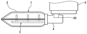
本発明に係る燃料用フィルタ装置をサクションフィルタ1に適用した第1実施形態について図1〜図11にしたがって参照して説明する。図1は、サクションフィルタ1を燃料ポンプ5に適用した装置を示す模式図である。
第2実施形態では、フィルタ部材2の他の形態について、図12〜図22にしたがって説明する。図12は、第2実施形態の燃料用フィルタ装置に適用されるフィルタ部材2Aの構成を示す模式的断面図である。図12において同一符号を付した構成部品は、第1実施形態と同一であり、同様の作用効果を奏する。また、第2実施形態の燃料用フィルタ装置は、フィルタ部材2Aを除く他の構成については第1実施形態の燃料用フィルタ装置と同一であり、同様の作用効果を奏する。
第3実施形態は、フィルタ部材2Eについて図23を参照して説明する。図23は、第3実施形態の燃料用フィルタ装置に適用されるフィルタ部材2Eの構成を示す模式的断面図である。図23において同一符号を付した構成部品は、第2実施形態と同一であり、同様の作用効果を奏する。また、第3実施形態の燃料用フィルタ装置は、フィルタ部材2Eを除く他の構成については第2実施形態の燃料用フィルタ装置と同一であり、同様の作用効果を奏する。
第4実施形態は、フィルタ部材2Fについて図24を参照して説明する。図24は、第4実施形態の燃料用フィルタ装置に適用されるフィルタ部材2Fの構成を示す模式的断面図である。図24において同一符号を付した構成部品は、第2実施形態と同一であり、同様の作用効果を奏する。また、第4実施形態の燃料用フィルタ装置は、フィルタ部材2Fを除く他の構成については第2実施形態の燃料用フィルタ装置と同一であり、同様の作用効果を奏する。
第5実施形態は、本発明を適用した燃料用フィルタ装置の他の形態である。第5実施形態の燃料用フィルタ装置は、燃料ポンプの下流側に設けられるフィルタ部材2Gを備える。図25は、第5実施形態の燃料用フィルタ装置の構成を示す模式的断面図である。図25において同一符号を付した構成部品は、前述の第2実施形態及び第3実施形態と同一であり、同様の作用効果を奏する。また、第5実施形態のフィルタ部材2Gは、前述の第2実施形態と同様の作用効果を奏する。
第6実施形態は、本発明を適用した燃料用フィルタ装置の他の形態である。第6実施形態の燃料用フィルタ装置は、第5実施形態と同様に燃料ポンプの下流側に設けられるフィルタ部材2Hを備える。図26は、第6実施形態の燃料用フィルタ装置の構成を示す模式的断面図である。図26において同一符号を付した構成部品は、前述の第1実施形態及び第5実施形態と同一であり、同様の作用効果を奏する。また、第6実施形態のフィルタ部材2Hは、前述の第1実施形態と同様の作用効果を奏する。
第7実施形態は、本発明を適用した燃料用フィルタ装置の他の形態である。第7実施形態の燃料用フィルタ装置は、燃料ポンプの下流側に設けられるフィルタ部材2Iを備える。図27は第6実施形態のフィルタ部材2Iの構成を示す模式的断面図である。図28は、第5実施形態の燃料用フィルタ装置の構成を示す模式的断面図である。図27及び図28において同一符号を付した構成部品は、前述の第1実施形態及び第6実施形態と同一であり、同様の作用効果を奏する。また、第7実施形態のフィルタ部材2Iは、前述の第1実施形態及び第6実施形態と同様の作用効果を奏する。
以上、本発明の好ましい実施形態について説明したが、本発明は上述した実施形態に何ら制限されることなく、本発明の主旨を逸脱しない範囲において種々変形して実施することが可能である。
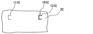
2,2A,2E,2F…フィルタ部材
10,10A…第1の濾過層(濾過層)
11,11A…第2の濾過層(濾過層)
12,12A…第3の濾過層(濾過層)
13,13A…第4の濾過層(濾過層)
20,21,22…隙間
20E…第1の中間層(中間層)
21E…第2の中間層(中間層)
22E…第3の中間層(中間層)
101…第1貫通孔(燃料通過量可変部、貫通孔)
101A…第1切込み部(燃料通過量可変部、開口面積可変部、切込み部)
101E,111E,121E…細隙(燃料通過量可変部、開口面積可変部)
111…第2貫通孔(燃料通過量可変部、貫通孔)
111A…第2切込み部(燃料通過量可変部、開口面積可変部、切込み部)
121…第3貫通孔(燃料通過量可変部、貫通孔)
121A…第3切込み部(燃料通過量可変部、開口面積可変部、切込み部)
Claims (10)
- 厚み方向に積層された複数の濾過層を含むフィルタ部材を備え、燃料が前記フィルタ部材を前記厚み方向に通過するときに前記燃料に含まれる異物を除去する燃料用フィルタ装置であって、
前記フィルタ部材は、前記厚み方向に隣り合う前記濾過層の間に隙間を設けた構成であり、
前記複数の濾過層のうち少なくとも一つの濾過層には、所定の開口面積を有する貫通孔が形成されており、
前記貫通孔は、はじめは前記燃料が濾材部分である他の部分を通過し、前記フィルタ部材を通過する前記燃料の通過量が累積して前記異物の除去が進行していく過程で、前記他の部分の目詰まりが限界に達する前に前記燃料が前記他の部分を通過しないで前記貫通孔を通過するようになる開口面積に設定されていることを特徴とする燃料用フィルタ装置。 - 厚み方向に積層された複数の濾過層を含むフィルタ部材を備え、燃料が前記フィルタ部材を前記厚み方向に通過するときに前記燃料に含まれる異物を除去する燃料用フィルタ装置であって、
前記フィルタ部材は、前記厚み方向に隣り合う前記濾過層の間に当該濾過層よりも空隙率の大きい中間層を介在させた構成であり、
前記複数の濾過層のうち少なくとも一つの濾過層には、所定の開口面積を有する貫通孔が形成されており、
前記貫通孔は、はじめは前記燃料が濾材部分である他の部分を通過し、前記フィルタ部材を通過する前記燃料の通過量が累積して前記異物の除去が進行していく過程で、前記他の部分の目詰まりが限界に達する前に前記燃料が前記他の部分を通過しないで前記貫通孔を通過するようになる開口面積に設定されていることを特徴とする燃料用フィルタ装置。 - 前記貫通孔が満たす前記圧力損失は、1.5kPa〜4kPaの範囲であることを特徴とする請求項1または請求項2に記載の燃料用フィルタ装置。
- 前記貫通孔は、前記厚み方向に隣り合う前記濾過層のそれぞれについて、前記厚み方向に重ならないように、前記厚み方向に対して直角な方向に互いにずれた位置に設けられていることを特徴とする請求項1から請求項3のいずれか一項に記載の燃料用フィルタ装置。
- 前記貫通孔は、前記燃料流れの最も下流に位置する濾過層を除く最も空隙率の小さい濾過層に設けられることを特徴とする請求項1から請求項4のいずれか一項に記載の燃料用フィルタ装置。
- 厚み方向に積層された複数の濾過層を含むフィルタ部材を備え、燃料が前記フィルタ部材を前記厚み方向に通過するときに前記燃料に含まれる異物を除去する燃料用フィルタ装置であって、
前記フィルタ部材は、前記厚み方向に隣り合う前記濾過層の間に隙間を設けた構成であり、
前記複数の濾過層のうち少なくとも一つの濾過層には、前記濾過層が撓むことによって拡大開口する開口面積可変部が形成されており、
はじめは前記燃料が濾材部分である他の部分を通過し、前記フィルタ部材を通過する前記燃料の通過量が累積して前記異物の除去が進行していく過程で前記他の部分が目詰まり状態になると前記燃料が流れるときの流動圧力により前記目詰まり状態の濾過層が前記燃料流れ下流の濾過層側に撓むことに伴って前記開口面積可変部は拡大開口し、前記燃料は当該拡大開口した前記開口面積可変部を通過して前記燃料流れ下流の濾過層に流入することを特徴とする燃料用フィルタ装置。 - 厚み方向に積層された複数の濾過層を含むフィルタ部材を備え、燃料が前記フィルタ部材を前記厚み方向に通過するときに前記燃料に含まれる異物を除去する燃料用フィルタ装置であって、
前記フィルタ部材は、前記厚み方向に隣り合う前記濾過層の間に当該濾過層よりも空隙率の大きい中間層を介在させた構成であり、
前記複数の濾過層のうち少なくとも一つの濾過層には、前記濾過層が撓むことによって拡大開口する開口面積可変部が形成されており、
はじめは前記燃料が濾材部分である他の部分を通過し、前記フィルタ部材を通過する前記燃料の通過量が累積して前記異物の除去が進行していく過程で前記他の部分が目詰まり状態になると前記燃料が流れるときの流動圧力により前記目詰まり状態の濾過層が前記燃料流れ下流の濾過層側に撓むことに伴って前記開口面積可変部は拡大開口し、前記燃料は当該拡大開口した前記開口面積可変部を通過して前記燃料流れ下流の濾過層に流入することを特徴とする燃料用フィルタ装置。 - 前記開口面積可変部は、前記厚み方向に隣り合う前記濾過層のそれぞれについて、前記厚み方向に重ならないように、前記厚み方向に対して直角な方向に互いにずれた位置に設けられていることを特徴とする請求項6または請求項7に記載の燃料用フィルタ装置。
- 前記開口面積可変部は、前記燃料流れの最も下流に位置する濾過層を除く最も空隙率の小さい濾過層に設けられることを特徴とする請求項6から請求項8のいずれか一項に記載の燃料用フィルタ装置。
- 前記開口面積可変部は、前記濾過層を貫通する切込み部または細隙であることを特徴とする請求項6から請求項9のいずれか一項に記載の燃料用フィルタ装置。
Priority Applications (2)
| Application Number | Priority Date | Filing Date | Title |
|---|---|---|---|
| JP2010193270A JP5126321B2 (ja) | 2010-01-19 | 2010-08-31 | 燃料用フィルタ装置 |
| US13/009,113 US20110174704A1 (en) | 2010-01-19 | 2011-01-19 | Fuel filter device |
Applications Claiming Priority (3)
| Application Number | Priority Date | Filing Date | Title |
|---|---|---|---|
| JP2010009371 | 2010-01-19 | ||
| JP2010009371 | 2010-01-19 | ||
| JP2010193270A JP5126321B2 (ja) | 2010-01-19 | 2010-08-31 | 燃料用フィルタ装置 |
Publications (2)
| Publication Number | Publication Date |
|---|---|
| JP2011169310A JP2011169310A (ja) | 2011-09-01 |
| JP5126321B2 true JP5126321B2 (ja) | 2013-01-23 |
Family
ID=44276775
Family Applications (1)
| Application Number | Title | Priority Date | Filing Date |
|---|---|---|---|
| JP2010193270A Active JP5126321B2 (ja) | 2010-01-19 | 2010-08-31 | 燃料用フィルタ装置 |
Country Status (2)
| Country | Link |
|---|---|
| US (1) | US20110174704A1 (ja) |
| JP (1) | JP5126321B2 (ja) |
Cited By (1)
| Publication number | Priority date | Publication date | Assignee | Title |
|---|---|---|---|---|
| US12110850B2 (en) * | 2022-01-17 | 2024-10-08 | Subaru Corporation | Pressure regulation device |
Families Citing this family (14)
| Publication number | Priority date | Publication date | Assignee | Title |
|---|---|---|---|---|
| JP5919824B2 (ja) * | 2012-01-05 | 2016-05-18 | セントラル硝子株式会社 | ガス生成装置 |
| JP6016079B2 (ja) * | 2012-07-13 | 2016-10-26 | 株式会社リコー | 流体浄化装置 |
| JP6053486B2 (ja) * | 2012-12-06 | 2016-12-27 | 株式会社ニフコ | フィルター |
| US10130903B2 (en) * | 2013-01-31 | 2018-11-20 | Filtran Llc | Filter with dual pleat pack |
| US10012118B2 (en) * | 2013-01-31 | 2018-07-03 | Filtran Llc | Filter with dual pleat pack |
| US9089791B2 (en) * | 2013-03-14 | 2015-07-28 | Cummins Ip, Inc. | Apparatus, method, and system for reductant filtration |
| JP2015025377A (ja) * | 2013-07-24 | 2015-02-05 | 株式会社日本自動車部品総合研究所 | 燃料濾過装置 |
| US9821255B2 (en) * | 2014-08-01 | 2017-11-21 | Hamilton Sundstrand Corporation | Screen and screen elements for fuel systems |
| US11598299B1 (en) * | 2017-01-24 | 2023-03-07 | Exergy Engineering Llc | Fuel filter |
| US10302059B2 (en) * | 2017-01-24 | 2019-05-28 | Caterpillar Inc. | Filter for a fuel injector |
| CN113423487A (zh) * | 2019-02-28 | 2021-09-21 | 富士胶片株式会社 | 细胞分离过滤器、过滤装置及细胞分离过滤器的制造方法 |
| US11826682B2 (en) | 2021-08-24 | 2023-11-28 | Filtran Llc | Flow control elements and fluid apparatus including the same |
| JP7785556B2 (ja) * | 2022-02-08 | 2025-12-15 | 愛三工業株式会社 | フィルタ装置 |
| WO2025025093A1 (zh) * | 2023-07-31 | 2025-02-06 | 宜昌邦普循环科技有限公司 | 一种纤维球过滤器 |
Family Cites Families (9)
| Publication number | Priority date | Publication date | Assignee | Title |
|---|---|---|---|---|
| US5223154A (en) * | 1991-11-01 | 1993-06-29 | Emcon Northwest, Inc. | System for filtering liquids in a catch basin using filters in series and overflow channels |
| US6113781A (en) * | 1993-09-15 | 2000-09-05 | Parker-Hannifin Corporation | Fuel filter with dual flow |
| US20080154214A1 (en) * | 2006-12-22 | 2008-06-26 | Medrad, Inc. | Flow Based Pressure Isolation and Fluid Delivery System Including Flow Based Pressure Isolation |
| JP4302458B2 (ja) * | 2003-07-31 | 2009-07-29 | 株式会社ニフコ | 燃料用フィルタ装置 |
| JP4342282B2 (ja) * | 2003-11-25 | 2009-10-14 | 旭化成せんい株式会社 | フィルター材 |
| US20090120869A1 (en) * | 2004-10-28 | 2009-05-14 | Robert Bosch Gmbh | Fuel injector filter |
| US7527671B1 (en) * | 2005-11-15 | 2009-05-05 | Sandia Corporation | Regenerable particulate filter |
| CN101472654B (zh) * | 2006-06-20 | 2015-06-10 | 卡明斯过滤Ip有限公司 | 含多种滤质的可更换过滤件和相关过滤系统、工艺及方法 |
| JP2009125737A (ja) * | 2007-11-28 | 2009-06-11 | Wako Filter Technology Kk | プレ燃料フィルタ |
-
2010
- 2010-08-31 JP JP2010193270A patent/JP5126321B2/ja active Active
-
2011
- 2011-01-19 US US13/009,113 patent/US20110174704A1/en not_active Abandoned
Cited By (1)
| Publication number | Priority date | Publication date | Assignee | Title |
|---|---|---|---|---|
| US12110850B2 (en) * | 2022-01-17 | 2024-10-08 | Subaru Corporation | Pressure regulation device |
Also Published As
| Publication number | Publication date |
|---|---|
| JP2011169310A (ja) | 2011-09-01 |
| US20110174704A1 (en) | 2011-07-21 |
Similar Documents
| Publication | Publication Date | Title |
|---|---|---|
| JP5126321B2 (ja) | 燃料用フィルタ装置 | |
| US8372278B1 (en) | Liquid fuel strainer assembly | |
| CN103025404B (zh) | 用于在滤中滤的筒中使用的模块化过滤单元 | |
| CN102893015B (zh) | 一种改进的内燃机燃油过滤器组及其滤芯 | |
| JP5611758B2 (ja) | 燃料用フィルター | |
| JP2006501058A (ja) | 多層プリーツ支持体を備えたろ材を有するフィルタ要素 | |
| EP2143934A1 (en) | Filter apparatus for fuel | |
| US20150165352A1 (en) | Filter element | |
| CN104667628A (zh) | 大体积凝聚过滤介质及其使用 | |
| JP2006326515A (ja) | フィルタ | |
| KR101760572B1 (ko) | 필터 | |
| JP2009125748A (ja) | フィルタエレメント | |
| CN121222126A (zh) | 穿孔层聚结器 | |
| CN110035814A (zh) | 过滤元件 | |
| KR102468898B1 (ko) | 액체 필터 및 액체 필터를 포함한 탱크 필터 시스템 | |
| US20230364538A1 (en) | System and method for fluid filtration | |
| CN108778460A (zh) | 用于燃料过滤器的滤芯的过滤材料、滤芯和燃料过滤器 | |
| WO2019023121A1 (en) | FILTER ELEMENT WITH SPACING ELEMENT | |
| JP5077141B2 (ja) | フィルタ | |
| JP6942122B2 (ja) | 一以上の湿式合成繊維層を用いる燃料フィルター | |
| KR101960646B1 (ko) | 오일 필터용 필터 디바이스 | |
| CN109416006B (zh) | 水分凝集器、燃料过滤装置、以及水分凝集器的制造方法 | |
| JP5821774B2 (ja) | 燃料フィルタ用フィルタエレメントおよびそれを備える燃料フィルタ装置 | |
| DE102014015942A1 (de) | Koaleszenzelement und Filterelement mit einem Koaleszenzelement | |
| JP6614982B2 (ja) | 不織布濾過材 |
Legal Events
| Date | Code | Title | Description |
|---|---|---|---|
| A621 | Written request for application examination |
Free format text: JAPANESE INTERMEDIATE CODE: A621 Effective date: 20110524 |
|
| A131 | Notification of reasons for refusal |
Free format text: JAPANESE INTERMEDIATE CODE: A131 Effective date: 20120515 |
|
| A521 | Request for written amendment filed |
Free format text: JAPANESE INTERMEDIATE CODE: A523 Effective date: 20120712 |
|
| TRDD | Decision of grant or rejection written | ||
| A01 | Written decision to grant a patent or to grant a registration (utility model) |
Free format text: JAPANESE INTERMEDIATE CODE: A01 Effective date: 20121002 |
|
| A01 | Written decision to grant a patent or to grant a registration (utility model) |
Free format text: JAPANESE INTERMEDIATE CODE: A01 |
|
| A61 | First payment of annual fees (during grant procedure) |
Free format text: JAPANESE INTERMEDIATE CODE: A61 Effective date: 20121015 |
|
| R151 | Written notification of patent or utility model registration |
Ref document number: 5126321 Country of ref document: JP Free format text: JAPANESE INTERMEDIATE CODE: R151 |
|
| FPAY | Renewal fee payment (event date is renewal date of database) |
Free format text: PAYMENT UNTIL: 20151109 Year of fee payment: 3 |
|
| R250 | Receipt of annual fees |
Free format text: JAPANESE INTERMEDIATE CODE: R250 |
|
| R250 | Receipt of annual fees |
Free format text: JAPANESE INTERMEDIATE CODE: R250 |
|
| R250 | Receipt of annual fees |
Free format text: JAPANESE INTERMEDIATE CODE: R250 |
|
| R250 | Receipt of annual fees |
Free format text: JAPANESE INTERMEDIATE CODE: R250 |
|
| R250 | Receipt of annual fees |
Free format text: JAPANESE INTERMEDIATE CODE: R250 |
|
| R250 | Receipt of annual fees |
Free format text: JAPANESE INTERMEDIATE CODE: R250 |
|
| R250 | Receipt of annual fees |
Free format text: JAPANESE INTERMEDIATE CODE: R250 |
|
| R250 | Receipt of annual fees |
Free format text: JAPANESE INTERMEDIATE CODE: R250 |
|
| S111 | Request for change of ownership or part of ownership |
Free format text: JAPANESE INTERMEDIATE CODE: R313113 |
|
| R350 | Written notification of registration of transfer |
Free format text: JAPANESE INTERMEDIATE CODE: R350 |
|
| R250 | Receipt of annual fees |
Free format text: JAPANESE INTERMEDIATE CODE: R250 |
|
| R250 | Receipt of annual fees |
Free format text: JAPANESE INTERMEDIATE CODE: R250 |
|
| R250 | Receipt of annual fees |
Free format text: JAPANESE INTERMEDIATE CODE: R250 |