JP5132246B2 - Projection display - Google Patents
Projection display Download PDFInfo
- Publication number
- JP5132246B2 JP5132246B2 JP2007273427A JP2007273427A JP5132246B2 JP 5132246 B2 JP5132246 B2 JP 5132246B2 JP 2007273427 A JP2007273427 A JP 2007273427A JP 2007273427 A JP2007273427 A JP 2007273427A JP 5132246 B2 JP5132246 B2 JP 5132246B2
- Authority
- JP
- Japan
- Prior art keywords
- housing
- laser light
- cover
- light source
- detection unit
- Prior art date
- Legal status (The legal status is an assumption and is not a legal conclusion. Google has not performed a legal analysis and makes no representation as to the accuracy of the status listed.)
- Expired - Fee Related
Links
Images




Landscapes
- Projection Apparatus (AREA)
- Semiconductor Lasers (AREA)
Description
本発明は、レーザ光源から出射するレーザ光の出力を制御する投写型表示装置に関するものである。 The present invention relates to a projection display device that controls the output of laser light emitted from a laser light source.
投射型表示装置には、従来、水銀ランプなど比較的低輝度の光源を搭載していたが、近年、レーザ光源などの集光性に優れた光源を搭載する傾向にある。このような集光性に優れたレーザ光源を搭載した投射型表示装置を分解する際には、作業者の眼などをレーザ光から保護する必要がある。このため、レーザ光源を搭載した投射型表示装置が分解されて、レーザ光源が取り出された場合などには、レーザ光源の点灯をOFFさせるなどの安全手段を講じていた。 Conventionally, a projection display device has been mounted with a light source having a relatively low brightness such as a mercury lamp. However, in recent years, there is a tendency to mount a light source with excellent light collecting properties such as a laser light source. When disassembling such a projection display device equipped with such a laser light source with excellent light condensing properties, it is necessary to protect the eyes of the operator from the laser light. For this reason, when a projection display device equipped with a laser light source is disassembled and the laser light source is taken out, safety measures such as turning off the laser light source have been taken.
この安全手段として、特許文献1や非特許文献1に記載の機器(レーザ光源を搭載した機器)では、筐体の取り外しに対するインターロックの設置や、筐体が取り外された際に光源を遮断する手段、遮断の解除を行なう手段の設置が行なわれている。 As a safety measure, in the devices described in Patent Document 1 and Non-Patent Document 1 (equipment equipped with a laser light source), an interlock is installed to remove the housing, and the light source is shut off when the housing is removed. Means and means for releasing the blocking are installed.
しかしながら、上記従来の技術では、レーザ光を搭載した機器を分解した際に安全装置が作動しても、この安全装置が容易に解除されてしまうという問題があった。また、安全装置を解除する行為がレーザを強制発光させる行為と同義となり、安全装置の意義を損なうという問題点があった。また、レーザ光源から眼などを保護する安全装置は業務用機器や産業機器などの特殊な設備に配設されており、装置構成が複雑であるとともに、安全装置の設置に高コストを要するという問題があった。 However, the above-described conventional technique has a problem that even when a safety device is activated when a device equipped with laser light is disassembled, the safety device is easily released. Further, the act of releasing the safety device is synonymous with the act of forcibly emitting the laser, and there is a problem that the significance of the safety device is impaired. In addition, safety devices that protect the eyes from laser light sources are installed in special equipment such as business equipment and industrial equipment, and the configuration of the equipment is complicated and the installation of the safety equipment requires high costs. was there.
本発明は、上記に鑑みてなされたものであって、簡易な構成で安価にレーザ光の漏洩を防止する投射型表示装置を得ることを目的とする。 The present invention has been made in view of the above, and an object of the present invention is to obtain a projection display device that prevents leakage of laser light at a low cost with a simple configuration.
上述した課題を解決し、目的を達成するために、本発明は、レーザ光源からレーザ光を出射してスクリーンにレーザ光を投射し、前記スクリーンに画像を表示する投射型表示装置において、前記レーザ光源および前記レーザ光源から前記スクリーンまでのレーザ伝達光路を包囲する筐体と、前記筐体に設けられた開口部に取り付けられることによって前記開口部を覆う開口部カバーと、前記開口部から前記開口部カバーが取り外された状態である前記筐体の開状態を検出する状態検出部と、前記状態検出部が前記筐体の開状態を検出している間は前記レーザ光源に前記レーザ光の出射を停止させる出力制御部と、前記レーザ光の出射の停止を解除して前記レーザ光を出射させる解除コマンドが入力される解除コマンド入力部と、を備え、前記筐体は、前記開口部カバーの挿入口として所定方向に曲げられた挿入口を有するとともに、前記開口部カバーは、前記挿入口に挿入される所定方向に曲げられた挿入部を有し、前記状態検出部は、前記挿入部が前記挿入口の所定位置まで挿入されていない状態の場合に、前記筐体の開状態を検出し、前記解除コマンドが入力されただけではレーザの出射はなされず、前記状態検出部が前記筐体の開状態を検出していない状態で前記解除コマンド入力部に前記解除コマンドが入力されると、前記レーザ光源に前記レーザ光の出射を許可することを特徴とする。 In order to solve the above-described problems and achieve the object, the present invention provides a projection display apparatus that emits laser light from a laser light source, projects the laser light on a screen, and displays an image on the screen. A housing that surrounds a light source and a laser transmission optical path from the laser light source to the screen, an opening cover that covers the opening by being attached to an opening provided in the housing, and the opening to the opening A state detection unit that detects an open state of the housing in a state in which a cover is removed, and emission of the laser light to the laser light source while the state detection unit detects the open state of the housing. the provided output control unit stopping, and a release command input unit the release command to exit is input to the laser light and cancels the stop of emission of the laser beam, the The body has an insertion port bent in a predetermined direction as an insertion port of the opening cover, and the opening cover has an insertion portion bent in a predetermined direction to be inserted into the insertion port, and the state The detection unit detects the open state of the housing when the insertion unit is not inserted up to a predetermined position of the insertion port, and the laser is not emitted only by inputting the release command. When the release command is input to the release command input unit in a state where the state detection unit does not detect the open state of the housing, the laser light source is allowed to emit the laser light. .
この発明によれば、所定方向に曲げられた挿入部が挿入口の所定位置まで挿入されていない間は、レーザ光源に前記レーザ光の出射を停止させるので、簡易な構成で安価にレーザ光の漏洩を防止することが可能になるという効果を奏する。 According to the present invention, the laser light source stops emitting the laser light while the insertion portion bent in the predetermined direction is not inserted to the predetermined position of the insertion port. There is an effect that leakage can be prevented.
以下に、本発明に係る投射型表示装置の実施の形態を図面に基づいて詳細に説明する。なお、この実施の形態によりこの発明が限定されるものではない。 Embodiments of a projection display device according to the present invention will be described below in detail with reference to the drawings. Note that the present invention is not limited to the embodiments.
実施の形態1.
図1は、本発明の実施の形態1に係る投射型表示装置の構成を示す図である。投射型表示装置100は、自装置が分解された場合や故障した場合などの際に、使用者(視聴者や作業者)の安全を保護する安全機能を有したレーザTVなどの表示装置である。
Embodiment 1 FIG.
FIG. 1 is a diagram showing a configuration of a projection display apparatus according to Embodiment 1 of the present invention. The
投射型表示装置100は、レーザ光源1、接続部(カップリング機構)11,12、光ファイバ2、光学エンジン3、拡大投射レンズ5、スクリーン6、筐体20、カバー(開口部カバー)30、開閉状態検出部40、出力制御部50を有している。レーザ光源1、接続部11,12、光ファイバ2、光学エンジン3、拡大投射レンズ5、開閉状態検出部40、出力制御部50は、スクリーン6、筐体20、カバー30によって包囲(格納)されており、さらに加えて解除コマンド入力部61を有している。
The
レーザ光源1は、出力制御部50からの指示に基づいて、レーザ光の出射と停止を行なう。接続部11は、レーザ光源1と光ファイバ2を接続するとともに、レーザ光源1からのレーザ光を光ファイバ2に送る。
The laser light source 1 emits and stops laser light based on an instruction from the
光ファイバ2は、レーザ光源1からのレーザ光を伝播させて光学エンジン3側に送るレーザ伝達光路である。接続部12は、光ファイバ2と光学エンジン3を接続するとともに、光ファイバ2からのレーザ光を光学エンジン3に送る。
The
光学エンジン3は、ミラー10、表示デバイス4を備えている。ミラー10は、接続部12を介して送られてくるレーザ光を表示デバイス4へ導き、レーザ光を表示デバイス4に照射する。
The optical engine 3 includes a
表示デバイス4は、例えば、DMD(Digital Micro-mirror Device)(登録商標)などの反射型光変調素子である。表示デバイス4は、ミラー10から送られてくるレーザ光を拡大投射レンズ5へ送り出す。拡大投射レンズ5は、表示デバイス4からのレーザ光を拡大してスクリーン6に投射するレンズである。スクリーン6は、拡大投射レンズ5によって投射された光を画像として表示する。
The display device 4 is a reflective light modulation element such as DMD (Digital Micro-mirror Device) (registered trademark). The display device 4 sends the laser light sent from the
筐体20は、その内部にレーザ光源1、接続部11,12、光ファイバ2、光学エンジン3、拡大投射レンズ5、スクリーン6、筐体20、カバー30、開閉状態検出部40、出力制御部50を配設する。筐体20は、所定の位置に開口部が設けられており、この開口部にカバー30が取り付けられる。筐体20の開口部は、例えば、筐体20内の部品(レーザ光源1など)を修理する工具などを、筐体20内に入れたり、筐体20から出したりする際の搬送口として用いられる。
The
カバー30は、筐体20の開口部に取り付けられて、筐体20内からのレーザ光の漏洩を防止する。投射型表示装置100は、筐体20およびスクリーン6によって光学的に密閉されており、カバー30が筐体20に取り付けられた状態では、スクリーン6以外からレーザ光が外に漏れることはなく、使用者の安全が保たれている。カバー30は、投射型表示装置100を修理や分解する際などに開口部から取り外される。
The
本実施の形態では、筐体20に、カバー30の挿入口として所定方向に曲げられた挿入口を配設しておき、カバー30には、挿入口に挿入される所定方向に曲げられた挿入部(後述の挿入部32)を配設しておく。
In the present embodiment, the
開閉状態検出部40は、機械スイッチ(センサー)41を備えており、機械スイッチ41からの信号(機械スイッチ41が押下されているか否かの信号)に基づいて、カバー30が筐体20に取り付けられているか否か(筐体20の開閉状態)を検出する。機械スイッチ41は、カバー30と接触した状態の場合に、機械スイッチ41が押下されていることを示す信号を開閉状態検出部40に送る。機械スイッチ41は、カバー30が機械スイッチ41から離れた場合に、機械スイッチ41が押下されていないことを示す信号を開閉状態検出部40に送る。開閉状態検出部40は、出力制御部50に接続されており、筐体20の開閉状態(検出結果)に関する情報(開閉状態情報)を出力制御部50に送る。
The open / close state detection unit 40 includes a mechanical switch (sensor) 41, and the
出力制御部50は、レーザ光源1に接続されており、開閉状態検出部40から送られてくる筐体20の開閉状態情報に基づいて、レーザ光源1のレーザ出力(レーザ光の出射)を制御する。本実施の形態の出力制御部50は、カバー30が筐体20に取り付けられている場合(筐体20が閉状態の場合)にレーザ光源1からレーザ光を出射させ、カバー30が筐体20から取り外されている場合(筐体20が開状態の場合)にレーザ光源1からのレーザ光の出射を停止させる。換言すると、使用者が投射型表示装置100の分解を試み、筐体20からカバー30を外すと、開閉状態検出部40が筐体20の開状態を検出し、レーザ光源1から出射するレーザ光を遮断させる。また、筐体20にカバー30が取り付けられると、開閉状態検出部40が筐体20の閉状態を検出し、出力制御部50がレーザ光源1にレーザ光の出射許可を与える。
The
つぎに、筐体20、筐体20の開口部、カバー30の構成を詳細に説明する。投射型表示装置100の修理などを行なう専門作業者は、筐体20に取り付けられているカバー30を筐体20から取り外し、内部構成物(レーザ光源1など)の修理などを行う。
Next, the configuration of the
使用者が、筐体20からカバー30を取り外した場合には機械スイッチ41が作動してOFFになり、レーザ光源1は遮断(出射停止)されて使用者の安全を保護できる。また、カバー30を再び筐体20に取り付け直した場合には、機械スイッチ41がONになり、レーザ光源1が再び作動する。ところが、使用者がカバー30を筐体20に取り付けることなく、故意または偶然に指や棒状の工具などによって機械スイッチ41に触り、機械スイッチ41をONにさせた場合(機械スイッチ41に筐体20の閉状態を検知させた場合)、カバー30が開口部を閉ざしていないにも関わらずレーザ光源1が点灯(レーザ光が出射)されレーザ光が使用者(人体)に照射されてしまう場合が生じる。
When the user removes the
そこで、本実施の形態では、機械スイッチ41がOFFになった後、機械スイッチ41が容易にONにならないよう(開閉状態検出部40が筐体20の開状態を検出した後、筐体20の閉状態を容易に検出させないよう)、カバー30や筐体20の形状に凹凸形状や段差を設けておく。換言すると、レーザ光源1から出射するレーザ光を停止させた後は出射の停止状態を容易に解除できないよう、筐体20の開口部内部(カバー30の挿入口)を所定方向に1〜複数回曲げておく。また、カバー30には、1〜複数回曲げられた挿入口に挿入できるよう、所定方向に1〜複数回曲げた部材(挿入部32)を配設しておく。
Therefore, in the present embodiment, after the
具体的には、本実施の形態では、カバー30を単なるプレート状ではなく、プレート状の裏面(筐体20に取り付けた際に内壁面となる側)に鍵型形状を含んで構成される挿入部32を設けた形状とする。
Specifically, in the present embodiment, the
図2は、実施の形態1に係る投射型表示装置のカバーの形状を説明するための図である。図2では、投射型表示装置100を横から見た場合のカバー30の断面図を示している。同図に示すように、カバー30は、プレート状の基部31と、基部31の裏面側に配設される挿入部32と、を有している。
FIG. 2 is a diagram for explaining the shape of the cover of the projection display apparatus according to the first embodiment. FIG. 2 shows a cross-sectional view of the
基部31は、カバー30が筐体20の開口部に取り付けられた際に筐体20の外壁面(開口部近傍の主面)と略平行になる表面と、挿入部32が配設される裏面と、を有した略略プレート状をなしている。このプレート状の基部31は、紙面と垂直な方向に延びている。
The
カバー30は、基部31が開口部を覆うようにして筐体20に取り付けられることによって、レーザ光の筐体20からの漏洩を防止する。このため、基部31の主面は、開口部よりも大きな面積を有している。基部31は、紙面と垂直な方向がプレート状の横方向であり、基部31の長手方向(紙面上の上下方向)がプレート状の縦方向である。したがって、図2に示す基部31の短手方向(紙面上の左右方向)がプレート状の厚さ方向である。
The
挿入部32は、一方の端部に基部31と接合されているプレート状の接合部34を有し、他方の端部にプレート状の先端部35を有し、接合部34と先端部35との間にプレート状の中央部36を有している。そして、接合部34は、中央部36の一方の端部で中央部36に接合し、先端部35は中央部36の他方の端部で中央部36に接合している。これらのプレート状が組み合わされた挿入部32は、基部31と同様に紙面と垂直な方向に延びている。
The
接合部34および先端部35は、紙面と垂直な方向がプレート状の横方向であり、紙面上の左右方向がプレート状の縦方向である。したがって、紙面上の上下方向がプレート状の厚さ方向である。
As for the joining
中央部36は、基部31と平行なプレート状をなしており、中央部36の縦方向、横方向、厚さ方向は、基部31の縦方向、横方向、厚さ方向と同じ方向である。また、接合部34と基部31とは、基部31の裏面側の上端部と下端部の間で接合部34の主面と基部31の主面とが垂直方向をなすよう接合されており、接合部34の縦方向と基部31の縦方向とがT字状をなしている。したがって、中央部36は、接合部34および先端部35と垂直に接合している。これにより、挿入部32では、プレート状の接合部34および先端部35が棚田状に配設され、接合部34および先端部35の主面に段差が設けられている。すなわち、接合部34と先端部35は、プレート状の主面が平行であり、かつ夫々の主面は異なる高さを有するよう中央部36に接合されている。
The
換言すると、挿入部32の断面形状は、図2に示すように接合部34と中央部36とによって鍵型形状をなすとともに、先端部35と中央部36とによって鍵型形状をなしている。
In other words, as shown in FIG. 2, the cross-sectional shape of the
また、カバー30は、基部31の裏面の一部(挿入部32よりも下側)と、接合部34と、中央部36と、によって凹部(紙面と垂直方向に延びる凹条)を構成しており、カバー30を筐体20に取り付けた場合には、この凹部が筐体20と係合する。
Further, the
また、先端部35は、その端面に基部31の主面と略平行な面を有した接触部37を備えており、カバー30を筐体20に取り付けた場合には、挿入部32が所定の位置まで挿入され、接触部37が機械スイッチ41を押下する。
Further, the
このように、本実施の形態では、基部31の裏面からは、基部31の裏面に垂直な方向に接合部34が延設され、接合部34の端部(基部31と反対側)からは、接合部34と垂直な方向(基部31の裏面と平行な方向)に中央部36が延設され、中央部36の端部からは、中央部36と垂直な方向(接合部34と平行な方向)に先端部35が延設されている。
Thus, in the present embodiment, the joining
本実施の形態では、カバー30を筐体20に取り付けやすくするとともに、筐体20からカバー30を取り外しやすくするため、カバー30を金属等の弾性を有した部材で構成しておく。
In the present embodiment, in order to make it easy to attach the
なお、挿入部32の横方向(紙面と垂直な方向)の寸法は、基部31の横方向と同じ長さであってもよいし基部31の横方向より短かくてもよい。また、接合部34、先端部35、中央部36はプレート状に限らず棒状であってもよい。接合部34、先端部35、中央部36が棒状である場合、基部31の主面に垂直な方向が接合部34や先端部35の棒状の長手方向となる。
The dimension of the
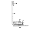
図3は、実施の形態1に係る投射型表示装置の筐体の形状を説明するための図であり、投射型表示装置100を横から見た場合の断面図を示している。図3では、筐体20うちカバー30が取り付けられる開口部近傍の断面図を示している。
FIG. 3 is a diagram for explaining the shape of the housing of the projection display device according to the first embodiment, and shows a cross-sectional view when the
同図に示すように、開口部近傍の筐体20は、上部側筐体21A、下部側筐体21B、中央部筐体21Cを有している。上部側筐体21A、下部側筐体21B、中央部筐体21Cは、それぞれ1つの部材(筐体20)として接合されている。したがって、上部側筐体21Aは、開口部の上部側に位置する筐体20の一部であり、下部側筐体21Bは、開口部の下部側に位置する筐体20の一部であり、中央部筐体21Cは、上部側筐体21Aと下部側筐体21Bとの間に位置する筐体20の一部である。
As shown in the drawing, the
上部側筐体21A、下部側筐体21B、中央部筐体21Cは、それぞれカバー30が筐体20に取り付けられる際に、カバー30と係合する係合面(係合面22a,22b,23〜27)を有している。
The
上部側筐体21Aは、下部側の一部(直方体)が削られており、この削り落とされた位置で、上部側筐体21Aと基部31とが係合させられる。上部側筐体21Aは、係合面22aで基部31の側面(上部)に係合し、係合面22bで基部31の裏面に係合する。
The
下部側筐体21Bは、カバー30の凹部に嵌め合わされる凸部や、筐体20の底面などを有している。下部側筐体21Bは、係合面23によって基部31の裏面に係合し、係合面24によって接合部34の主面(下面)に係合し、係合面25によって先端部35の下面(先端部35および中央部36からなる鍵型)と係合する。下部側筐体21Bでは、係合面23、係合面24、係合面25などによって挿入部32の凹部に嵌め合わされる凸部を構成している。
The lower housing 21 </ b> B has a convex portion that fits into the concave portion of the
本実施の形態では、カバー30の筐体20からの着脱を容易に行なわせるため、下部側筐体21Bの凸部を、挿入部32の凹部よりも小さくしておく。また、カバー30が筐体20に取り付けられる際に、接触部37によって機械スイッチ41が押下され、機械スイッチ41がON状態になるよう下部側筐体21B上(筐体20内)の所定の位置に機械スイッチ41を配設しておく。
In the present embodiment, the convex portion of the lower housing 21 </ b> B is made smaller than the concave portion of the
中央部筐体21Cは、係合面26によって先端部35の上面と係合し、係合面27によって中央部36の主面と係合する。これにより、中央部筐体21Cは、先端部35および中央部36からなる鍵型に係合する。そして、カバー30が筐体20に取り付けられる際には、上部側筐体21Aと、下部側筐体21Bと、中央部筐体21Cとによって、カバー30を挟持する。
The central housing 21 </ b> C is engaged with the upper surface of the
本実施の形態では、上部側筐体21Aと下部側筐体21Bとの間に形成されているカバー30の挿入方向(開口部に垂直な方向)と、下部側筐体21Bと中央部筐体21Cとの間に形成されているカバー30の挿入方向と、に段差を生じさせている。
In the present embodiment, the insertion direction (direction perpendicular to the opening) of the
換言すると、筐体20は、カバー30の挿入部32を挿入するための挿入口に複数の軸方向を有しており、直線上の棒部材や撓みの小さな部材を筐体20内に挿入した場合に、これらの部材が機械スイッチ41まで到達しないよう構成されている。このため、撓みの小さな棒状の工具などによって機械スイッチ41をOFF状態にすることが困難になっている。すなわち、筐体20からカバー30を取り外した状態では、特殊工具を用いることなく機械スイッチ41の開状態を解除することが容易ではない。
In other words, the
図4は、実施の形態1に係る投射型表示装置の筐体にカバーを取り付けた状態を説明するための図である。筐体20にカバー30を取り付ける際には、筐体20の開口部から挿入部32を挿入し、カバー30を撓ませながら、挿入部32を下部側筐体21Bと中央部筐体21Cとの間(挿入口)に挿入していく。具体的には、先端部35などを下部側筐体21Bや中央部筐体21Cなどに引っ掛けてカバー30を撓ませる。さらに、カバー30を撓ませた状態で、挿入部32を機械スイッチ41側へ挿入する。
FIG. 4 is a diagram for explaining a state in which a cover is attached to the housing of the projection display device according to the first embodiment. When attaching the
そして、上部側筐体21Aの係合面22a,22bに基部31の上部を係合させる。また、下部側筐体21Bの凸部を、カバー30の凹部に挿入する。さらに、係合面23に基部31の下部側の裏面を係合させ、係合面24に接合部34の下面を係合させ、係合面25に先端部35の下面を係合させる。さらに、係合面26に先端部35の上面を係合させ、係合面27に中央部36の主面(右面)を係合させる。
Then, the upper portion of the
カバー30の撓みを解放してカバー30を筐体20に取り付けると、接触部37によって機械スイッチ41が押下され、機械スイッチ41がON状態になる。一方、カバー30が筐体20から取り外されると、接触部37が機械スイッチ41から離れて、機械スイッチ41がOFF状態になる。
When the bending of the
この結果、たとえレーザ光源1が取り外されて使用者がレーザ光源1を直接見るようなことが起きても、レーザ光源1は動作していない状態なので人体の安全を保護することができる。 As a result, even if the laser light source 1 is removed and the user looks at the laser light source 1 directly, the safety of the human body can be protected because the laser light source 1 is not operating.
つぎに、投射型表示装置100の動作手順について説明する。図5は、実施の形態1に係る投射型表示装置の動作手順を示すフローチャートである。投射型表示装置100では、レーザ光源1の電源がONになると(ステップS110、Yes)、出力制御部50はレーザ光源1からレーザ光を出射させる(ステップS120)。
Next, an operation procedure of the
この後、開閉状態検出部40は、筐体20が開状態であるか閉状態であるかの検出を開始する。具体的には、開閉状態検出部40は、カバー30が筐体20から取り外されたか否かを検出する(ステップS130)。筐体20からカバー30が取り外されて、機械スイッチ41がONになると(機械スイッチ41から接触部37が離れると)、開閉状態検出部40は、筐体20の開状態を検出する。
Thereafter, the open / close state detection unit 40 starts detecting whether the
開閉状態検出部40が、筐体20の開状態を検出すると(ステップS130、Yes)、開閉状態検出部40は開閉状態情報として筐体20が開状態であることを出力制御部50に通知する。これにより、出力制御部50は、レーザ光源1にレーザ光の出射を停止させる(ステップS140)。レーザ光源1からのレーザ光の出射の停止は、レーザ光源1の電源をOFFすることによって行なってもよいし、所定のシャッターなどでレーザ光の出射を遮断してもよい。
When the open / close state detection unit 40 detects the open state of the housing 20 (step S130, Yes), the open / close state detection unit 40 notifies the
開閉状態検出部40は、カバー30が筐体20に取り付けられたか否かを検出する(ステップS150)。筐体20にカバー30が取り付けられて、機械スイッチ41がONになると(接触部37が機械スイッチ41を押下すると)、開閉状態検出部40は、筐体20の閉状態を検出する。
The open / close state detection unit 40 detects whether or not the
開閉状態検出部40が、筐体20の閉状態を検出すると(ステップS150、Yes)、開閉状態検出部40は開閉状態情報として筐体20が閉状態であることを出力制御部50に通知する。これにより、出力制御部50は、レーザ光源1の電源がONであれば、レーザ光源1からレーザ光を出射させる(ステップS110,S120)。
When the open / close state detection unit 40 detects the closed state of the housing 20 (Yes in step S150), the open / close state detection unit 40 notifies the
開閉状態検出部40が、レーザ光源1からレーザ光を出射させる際に、筐体20の開状態を検出しなければ(ステップS130、No)、開閉状態検出部40は開閉状態情報として筐体20が閉状態であることを出力制御部50に通知する。出力制御部50は、レーザ光源1の電源がONであれば、レーザ光源1にレーザ光の出射を維持させる(ステップS110,S120)。
When the open / close state detection unit 40 does not detect the open state of the
また、レーザ光源1からのレーザ光が出射停止している際に、開閉状態検出部40が、筐体20の閉状態を検出しなければ(ステップS150、No)、開閉状態検出部40は開閉状態情報として筐体20が開状態であることを出力制御部50に通知する。これにより、出力制御部50は、レーザ光源1にレーザ光の出射停止状態を維持させる(ステップS140)。投射型表示装置100では、レーザ光源1の電源がONの間、ステップS110〜S150の処理を繰り返す。
If the open / close state detection unit 40 does not detect the closed state of the
なお、カバー30と筐体20は、カバー30を筐体20に取り付けた状態でカバー30を筐体20にネジ留めしてもよい。また、カバー30を筐体20に取り付けやすくするとともに、筐体20からカバー30を取り外しやすくするため、カバー30を筐体20に取り付けた状態でのカバー30と筐体20との間(係合面)に所定量の隙間を設けてもよい。また、本実施の形態では、カバー30が弾性を有する場合について説明をしたが、筐体20が弾性を有する構成としてもよい。
The
また、カバー30や筐体20の形状は図2や図3に示した形状に限らない。カバー30や筐体20の形状は、弾性の小さな棒状部材や指などで機械スイッチ41を容易にONできない構造であればいずれの構造であってもよい。したがって、上部側筐体21A、下部側筐体21B、中央部筐体21Cによって形成される、挿入部32の挿入方向の段差は、何れの方向に設けてもよい。
Moreover, the shape of the
なお、本実施の形態では、筐体20に取り付けるカバー30が1つの場合について説明したが、筐体20に取り付けるカバー30は複数であってもよい。筐体20に複数のカバー30を取り付ける場合、筐体20には、カバー30の取り付け位置毎に、図3に示した上部側筐体21A、下部側筐体21B、中央部筐体21Cを配設するとともに、筐体20内にはカバー30毎に機械スイッチ41を設けておく。
In the present embodiment, the case where there is one
また、本実施の形態では、筐体20内に開閉状態検出部40や出力制御部50を配設する場合について説明したが、筐体20の外側に開閉状態検出部40や出力制御部50を配設してもよい。
In the present embodiment, the case where the open / close state detection unit 40 and the
このように、筐体20からカバー30が取り外された場合には、レーザ光の出射を確実に停止させることができる。また、筐体20は、鍵型形状を含んで構成される挿入部32と係合するよう、開口部近傍に上部側筐体21A、下部側筐体21B、中央部筐体21Cを有しているので、カバー30のような鍵型形状を含んで構成される形状の部材でなければ機械スイッチ41をONできない。このため、使用者は、カバー30を筐体20に取り付けることなく、機械スイッチ41をONにすることができない。したがって、レーザ光の出射を復旧させる際には、筐体20にカバー30が取り付けられた安全な状態で復旧させることができる。これにより、投射型表示装置100の修理作業や復旧動作をともに安全に行なうことが可能となる。
Thus, when the
このように実施の形態1によれば、使用者が投射型表示装置100の分解を試みた際に、筐体20からカバー30を取り外しただけで安全装置が作動し、レーザ光源1からのレーザ光を遮断するので、人体(使用者の眼や皮膚など)の安全を保護できる。
As described above, according to the first embodiment, when the user tries to disassemble the
また、カバー30を開口部に取り付ける際には、挿入部32の挿入方向を変えながら筐体20内に挿入する必要がある。したがって、レーザ光源1が遮断された後は、カバー30を再び筐体20の元の位置に正しく取り付けない限り、市販の工具などではレーザ光源1を出射させることができないので、使用者の安全を保護できる。
Further, when attaching the
また、投射型表示装置100には、カバー30に挿入部32を配設し、筐体20に挿入部32を挿入する箇所を設けるだけでよいので、簡易な構成で安価に使用者の安全を保護できる。
Further, since the
解除コマンド入力部61は、筐体20の外部に配設されており、出力制御部50に接続されている。使用者から解除コマンド入力部61に、レーザ光の遮断を解除させるためのコマンド(以下、解除コマンドという)が入力されると、解除コマンド入力部61は、この解除コマンドを出力制御部50に送る。
The release
本実施の形態の出力制御部50は、解除コマンド入力部61から解除コマンドが送られてきた場合に、レーザ光源1の出力をOFFからONにしてレーザ光を出射させる。出力制御部50は、開閉状態検出部40から筐体20が閉状態であることの通知を受けた場合であって、かつ解除コマンドを受けた場合にレーザ光源1からレーザ光を出射させてもよいし、開閉状態検出部40から筐体20が閉状態であることの通知を受けることなく、解除コマンドを受けた場合にレーザ光源1からレーザ光を出射させてもよい。
When a cancel command is sent from the cancel
図6は、実施の形態1に係る投射型表示装置が有する出力制御部50の構成を示す図である。出力制御部50は、制御マイコン(マイクロコンピュータ)52、ゲートパルス発生回路53を有しており、解除コマンド入力部61、フロントコントロールボタン62およびレーザ光源1に接続されている。
Figure 6 is a diagram showing a configuration of an
フロントコントロールボタン62は、投射型表示装置100(レーザ光源1)の電源をONまたはOFFさせるボタンであり、筐体20の外部に配設されている。使用者がフロントコントロールボタン62を押下すると、レーザ光源1の電源をONさせる信号が制御マイコン52に送られる。
The
制御マイコン52は、開閉状態検出部40から筐体20の開状態が通知されていなければ、レーザ光源1を出射させるケートパルスをゲートパルス発生回路53に発生させる。ゲートパルス発生回路53は、制御マイコン52からケートパルスを発生させる指示を受けると、ゲートパルスを発生させてレーザ光源1に送る。
If the open state of the
レーザ光源1は、電源71と、レーザ光を発生させるためのレーザダイオード72と、を有している。レーザ光源1は、ゲートパルス発生回路53からのゲートパルスに応じたレーザ光73をレーザダイオード72から出射する。
The laser light source 1 has a
つぎに、出力制御部50の動作手順(制御アルゴリズム)について説明する。図7は、出力制御部の動作手順を示すフローチャートである。使用者がフロントコントロールボタン62を押下すると、レーザ光源1の電源をONさせる信号が制御マイコン52に送られる。制御マイコン52は、ケートパルスの発生指示をゲートパルス発生回路53に送る。ゲートパルス発生回路53は、制御マイコン52からの指示に基づいてゲートパルスを発生させ、レーザ光源1に送る。レーザ光源1は、ゲートパルス発生回路53からのゲートパルスに応じたレーザ光73を出射する。
Next, an operation procedure (control algorithm) of the
開閉状態検出部40は、筐体20からカバー30が取り外されたか否か(筐体20の開閉状態)を機械スイッチ41によって検出する(ステップS210)。開閉状態検出部40が、筐体20からカバー30が取り外されたことを検出しなければ(ステップS220、No)、開閉状態検出部40は筐体20の閉状態を出力制御部50に通知する。これにより、出力制御部50の制御マイコン52は、ケートパルスの出力指示をゲートパルス発生回路53に送る。ゲートパルス発生回路53は、制御マイコン52からの指示に基づいて、ゲートパルスの発生をONしたままにする(ステップS225)。そして、出力制御部50は、レーザ光源1にレーザ光の出射を維持させる。
The open / close state detection unit 40 detects whether or not the
一方、開閉状態検出部40が、筐体20からカバー30が取り外されたことを検出すると(ステップS220、Yes)、開閉状態検出部40は筐体20の開状態を出力制御部50に通知する。これにより、出力制御部50の制御マイコン52は、ケートパルスの停止指示をゲートパルス発生回路53に送る。ゲートパルス発生回路53は、制御マイコン52からの指示に基づいて、ゲートパルスの発生をOFFにする(ステップS230)。そして、出力制御部50は、レーザ光源1から出射するレーザ光を遮断させる。
On the other hand, when the open / close state detection unit 40 detects that the
使用者から解除コマンド入力部61に、レーザ光の遮断を解除させるための解除コマンドが入力されなければ(ステップS240、No)、解除コマンド入力部61から出力制御部50へ解除コマンドが送られることはない。このため、ゲートパルス発生回路53は、ゲートパルスの発生をOFFしたままにする(ステップS225)。これにより、出力制御部50は、レーザ光源1からのレーザ光の遮断を維持させる。
If the cancel command for canceling the cutoff of the laser beam is not input from the user to the cancel command input unit 61 (No in step S240), the cancel command is sent from the cancel
一方、使用者から解除コマンド入力部61に、レーザ光の遮断を解除させるための解除コマンドが入力されると(ステップS240、Yes)、解除コマンド入力部61は、この解除コマンドを出力制御部50に送る。
On the other hand, when a cancel command for canceling the cutoff of the laser beam is input from the user to the cancel command input unit 61 (step S240, Yes), the cancel
出力制御部50の制御マイコン52は、解除コマンド入力部61からの解除コマンドを受けると、ケートパルスの出力指示をゲートパルス発生回路53に送る。ゲートパルス発生回路53は、制御マイコン52からの指示に基づいて、ゲートパルスの発生をONにする(ステップS250)。これにより、出力制御部50は、レーザ光源1にレーザ光を出射させる。また、解除コマンドの入力が有効になるためにはカバー30が取りつけられた状態になっていることが必用で、カバー30が取り外しを検出している状態では(ステップ220、No)たとえ解除コマンドが入力部61から入力されてもゲートパルス発生回路53へゲートパルスが送られることはない。
When receiving the release command from the release
このように実施の形態1によれば、一旦安全確保のためにレーザ光が遮断された場合、使用者などによって解除コマンドが入力されない限り(所定の手続きが行なわれない限り)、たとえ筐体20を元の位置に戻してもゲートパルスはONにならず、レーザ光源1はレーザ光を出射しない。したがって、カバー30を取り外した後、使用者が機械スイッチ41を動作させて安全装置を解除しようと試みてもレーザ光源1はレーザ光を出射せず安全を維持することができる。また、安全装置を解除するコマンドを入力しても、カバー30が取り付けた状態になっていない限りレーザ光を射出しようとしてもレーザは発光しないので、不用意な人体へのレーザ被爆を避けることができる。
As described above, according to the first embodiment, once the laser beam is interrupted to ensure safety, unless the release command is input by the user or the like (unless a predetermined procedure is performed), even the
なお、実施の形態1では、レーザ光の出力制御が行なわれる装置が投射型表示装置である場合について説明したが、レーザ光を光源とするLCD−TVなどに実施の形態1で説明したレーザ光の出力制御を適用してもよい。また、高出力のレーザ光を光源とする産業用装置(加工機など)の安全システムに実施の形態1で説明したレーザ光の出力制御を適用してもよい。例えば、レーザ光源1と、筐体20と、カバー30と、を有したレーザ光出射機構に開閉状態検出部40と出力制御部50を接続し、レーザ光源1から出射させるレーザ光の出射および停止を制御してもよい。
In the first embodiment, the case where the apparatus for controlling the output of the laser light is a projection display device has been described. However, the laser light described in the first embodiment is applied to an LCD-TV using the laser light as a light source. The output control may be applied. Further, the output control of the laser beam described in the first embodiment may be applied to a safety system of an industrial apparatus (such as a processing machine) that uses a high-power laser beam as a light source. For example, an open / close state detection unit 40 and an
以上のように、本発明に係る投射型表示装置は、レーザ光源から出射するレーザ光の出力制御に適している。 As described above, the projection display device according to the present invention is suitable for output control of laser light emitted from a laser light source.
1 レーザ光源
2 光ファイバ
3 光学エンジン
4 表示デバイス
5 拡大投射レンズ
6 スクリーン
10 ミラー
11,12 接続部
20 筐体
21A 上部側筐体
21B 下部側筐体
21C 中央部筐体
22a,22b,23〜27 係合面
30 カバー
31 基部
32 挿入部
34 接合部
35 先端部
36 中央部
37 接触部
40 開閉状態検出部
41 機械スイッチ
50 出力制御部
52 制御マイコン
53 ゲートパルス発生回路
61 解除コマンド入力部
62 フロントコントロールボタン
71 電源
72 レーザダイオード
73 レーザ光
100 投射型表示装置
DESCRIPTION OF SYMBOLS 1 Laser
Claims (1)
前記レーザ光源および前記レーザ光源から前記スクリーンまでのレーザ伝達光路を包囲する筐体と、
前記筐体に設けられた開口部に取り付けられることによって前記開口部を覆う開口部カバーと、
前記開口部から前記開口部カバーが取り外された状態である前記筐体の開状態を検出する状態検出部と、
前記状態検出部が前記筐体の開状態を検出している間は前記レーザ光源に前記レーザ光の出射を停止させる出力制御部と、
前記レーザ光の出射の停止を解除して前記レーザ光を出射させる解除コマンドが入力される解除コマンド入力部と、
を備え、
前記筐体は、前記開口部カバーの挿入口として所定方向に曲げられた挿入口を有するとともに、前記開口部カバーは、前記挿入口に挿入される所定方向に曲げられた挿入部を有し、
前記状態検出部は、前記挿入部が前記挿入口の所定位置まで挿入されていない状態の場合に、前記筐体の開状態を検出し、
前記解除コマンドが入力されただけではレーザの出射はなされず、前記状態検出部が前記筐体の開状態を検出していない状態で前記解除コマンド入力部に前記解除コマンドが入力されると、前記レーザ光源に前記レーザ光の出射を許可することを特徴とする投射型表示装置。 In a projection display device that emits laser light from a laser light source and projects laser light on a screen, and displays an image on the screen.
A housing enclosing the laser light source and a laser transmission optical path from the laser light source to the screen;
An opening cover that covers the opening by being attached to the opening provided in the housing;
A state detection unit for detecting an open state of the housing in a state where the opening cover is removed from the opening;
An output control unit that causes the laser light source to stop emitting the laser beam while the state detection unit detects the open state of the housing;
A cancellation command input unit for inputting a cancellation command for canceling the stop of the emission of the laser light and emitting the laser light,
With
The housing has an insertion port bent in a predetermined direction as an insertion port of the opening cover, and the opening cover has an insertion portion bent in a predetermined direction to be inserted into the insertion port,
The state detection unit detects an open state of the housing when the insertion unit is not inserted to a predetermined position of the insertion port ,
When the release command is input, laser emission is not performed, and when the release command is input to the release command input unit in a state where the state detection unit does not detect the open state of the housing, A projection-type display device , wherein a laser light source is allowed to emit the laser light .
Priority Applications (1)
| Application Number | Priority Date | Filing Date | Title |
|---|---|---|---|
| JP2007273427A JP5132246B2 (en) | 2007-10-22 | 2007-10-22 | Projection display |
Applications Claiming Priority (1)
| Application Number | Priority Date | Filing Date | Title |
|---|---|---|---|
| JP2007273427A JP5132246B2 (en) | 2007-10-22 | 2007-10-22 | Projection display |
Publications (2)
| Publication Number | Publication Date |
|---|---|
| JP2009103776A JP2009103776A (en) | 2009-05-14 |
| JP5132246B2 true JP5132246B2 (en) | 2013-01-30 |
Family
ID=40705539
Family Applications (1)
| Application Number | Title | Priority Date | Filing Date |
|---|---|---|---|
| JP2007273427A Expired - Fee Related JP5132246B2 (en) | 2007-10-22 | 2007-10-22 | Projection display |
Country Status (1)
| Country | Link |
|---|---|
| JP (1) | JP5132246B2 (en) |
Families Citing this family (8)
| Publication number | Priority date | Publication date | Assignee | Title |
|---|---|---|---|---|
| US8672427B2 (en) * | 2010-01-25 | 2014-03-18 | Pepsico, Inc. | Video display for product merchandisers |
| JP5349355B2 (en) * | 2010-02-01 | 2013-11-20 | 三菱電機株式会社 | Projection television and projection television screen unit fixing method |
| JP2011203622A (en) * | 2010-03-26 | 2011-10-13 | Seiko Epson Corp | Projector |
| CN104793455A (en) * | 2010-07-23 | 2015-07-22 | 日本电气株式会社 | Laser light source module |
| JP5901428B2 (en) * | 2012-05-24 | 2016-04-13 | 三菱電機株式会社 | Liquid crystal display |
| JP6631651B2 (en) | 2018-04-25 | 2020-01-15 | 株式会社島津製作所 | Scanning probe microscope and light intensity adjustment method |
| JP6631674B1 (en) | 2018-10-16 | 2020-01-15 | 株式会社島津製作所 | Surface analyzer |
| JP6631739B1 (en) | 2019-04-04 | 2020-01-15 | 株式会社島津製作所 | Surface analyzer |
Family Cites Families (6)
| Publication number | Priority date | Publication date | Assignee | Title |
|---|---|---|---|---|
| JP4590985B2 (en) * | 2004-08-31 | 2010-12-01 | セイコーエプソン株式会社 | Image display device |
| JP2006119460A (en) * | 2004-10-22 | 2006-05-11 | Okano Electric Wire Co Ltd | Laser pointer |
| JP2006195319A (en) * | 2005-01-17 | 2006-07-27 | Seiko Epson Corp | projector |
| JP2007017679A (en) * | 2005-07-07 | 2007-01-25 | Canon Inc | Encoder device and optical apparatus |
| JP2007249171A (en) * | 2006-02-16 | 2007-09-27 | Seiko Epson Corp | Rear projector |
| JP4254839B2 (en) * | 2006-10-12 | 2009-04-15 | 株式会社日立製作所 | Display device |
-
2007
- 2007-10-22 JP JP2007273427A patent/JP5132246B2/en not_active Expired - Fee Related
Also Published As
| Publication number | Publication date |
|---|---|
| JP2009103776A (en) | 2009-05-14 |
Similar Documents
| Publication | Publication Date | Title |
|---|---|---|
| JP5132246B2 (en) | Projection display | |
| JP4845850B2 (en) | Projection display | |
| US6929370B2 (en) | Projector with foreign matter detecting means | |
| JP2008180921A (en) | Projection display | |
| CN100545738C (en) | projection display device | |
| JP2010243921A (en) | Projection video display apparatus | |
| JP2000267621A (en) | Video display device | |
| EP2706409B1 (en) | Image projection apparatus | |
| JP2010175605A (en) | Projector apparatus | |
| JP2009237197A (en) | Portable projector device | |
| JP6281313B2 (en) | Image projection device | |
| JPH10239767A (en) | projector | |
| JP5125367B2 (en) | projector | |
| JP5029216B2 (en) | Projection apparatus, control method, and program | |
| JP2007034318A (en) | Projector with foreign matter sensor circuit | |
| JP2006119676A (en) | Projector with foreign substance sensor circuit | |
| JP2007033792A (en) | projector | |
| JP6167595B2 (en) | projector | |
| JP4402605B2 (en) | Fingerprint image pickup device | |
| JP2007287081A (en) | Tamper resistant method, tamper resistant device applying the same, and control program for tamper resistant device | |
| JPWO2020066067A1 (en) | Control device and control method | |
| JP2021012248A (en) | Projection type video display device and obstacle detection method | |
| JP2020177329A (en) | Cover device | |
| JP2012027055A (en) | Projector and projector control method | |
| JP5901428B2 (en) | Liquid crystal display |
Legal Events
| Date | Code | Title | Description |
|---|---|---|---|
| A621 | Written request for application examination |
Free format text: JAPANESE INTERMEDIATE CODE: A621 Effective date: 20100705 |
|
| A977 | Report on retrieval |
Free format text: JAPANESE INTERMEDIATE CODE: A971007 Effective date: 20120419 |
|
| A131 | Notification of reasons for refusal |
Free format text: JAPANESE INTERMEDIATE CODE: A131 Effective date: 20120424 |
|
| A521 | Request for written amendment filed |
Free format text: JAPANESE INTERMEDIATE CODE: A523 Effective date: 20120621 |
|
| TRDD | Decision of grant or rejection written | ||
| A01 | Written decision to grant a patent or to grant a registration (utility model) |
Free format text: JAPANESE INTERMEDIATE CODE: A01 Effective date: 20121009 |
|
| A01 | Written decision to grant a patent or to grant a registration (utility model) |
Free format text: JAPANESE INTERMEDIATE CODE: A01 |
|
| A61 | First payment of annual fees (during grant procedure) |
Free format text: JAPANESE INTERMEDIATE CODE: A61 Effective date: 20121106 |
|
| FPAY | Renewal fee payment (event date is renewal date of database) |
Free format text: PAYMENT UNTIL: 20151116 Year of fee payment: 3 |
|
| R150 | Certificate of patent or registration of utility model |
Free format text: JAPANESE INTERMEDIATE CODE: R150 Ref document number: 5132246 Country of ref document: JP Free format text: JAPANESE INTERMEDIATE CODE: R150 |
|
| R250 | Receipt of annual fees |
Free format text: JAPANESE INTERMEDIATE CODE: R250 |
|
| R250 | Receipt of annual fees |
Free format text: JAPANESE INTERMEDIATE CODE: R250 |
|
| R250 | Receipt of annual fees |
Free format text: JAPANESE INTERMEDIATE CODE: R250 |
|
| R250 | Receipt of annual fees |
Free format text: JAPANESE INTERMEDIATE CODE: R250 |
|
| R250 | Receipt of annual fees |
Free format text: JAPANESE INTERMEDIATE CODE: R250 |
|
| R250 | Receipt of annual fees |
Free format text: JAPANESE INTERMEDIATE CODE: R250 |
|
| LAPS | Cancellation because of no payment of annual fees |