JP5144502B2 - Implantable medical devices - Google Patents
Implantable medical devices Download PDFInfo
- Publication number
- JP5144502B2 JP5144502B2 JP2008509101A JP2008509101A JP5144502B2 JP 5144502 B2 JP5144502 B2 JP 5144502B2 JP 2008509101 A JP2008509101 A JP 2008509101A JP 2008509101 A JP2008509101 A JP 2008509101A JP 5144502 B2 JP5144502 B2 JP 5144502B2
- Authority
- JP
- Japan
- Prior art keywords
- atrial
- pacing
- test
- interval
- ventricular
- Prior art date
- Legal status (The legal status is an assumption and is not a legal conclusion. Google has not performed a legal analysis and makes no representation as to the accuracy of the status listed.)
- Expired - Lifetime
Links
Images





Classifications
-
- A—HUMAN NECESSITIES
- A61—MEDICAL OR VETERINARY SCIENCE; HYGIENE
- A61N—ELECTROTHERAPY; MAGNETOTHERAPY; RADIATION THERAPY; ULTRASOUND THERAPY
- A61N1/00—Electrotherapy; Circuits therefor
- A61N1/18—Applying electric currents by contact electrodes
- A61N1/32—Applying electric currents by contact electrodes alternating or intermittent currents
- A61N1/36—Applying electric currents by contact electrodes alternating or intermittent currents for stimulation
- A61N1/362—Heart stimulators
- A61N1/37—Monitoring; Protecting
- A61N1/371—Capture, i.e. successful stimulation
-
- A—HUMAN NECESSITIES
- A61—MEDICAL OR VETERINARY SCIENCE; HYGIENE
- A61N—ELECTROTHERAPY; MAGNETOTHERAPY; RADIATION THERAPY; ULTRASOUND THERAPY
- A61N1/00—Electrotherapy; Circuits therefor
- A61N1/18—Applying electric currents by contact electrodes
- A61N1/32—Applying electric currents by contact electrodes alternating or intermittent currents
- A61N1/36—Applying electric currents by contact electrodes alternating or intermittent currents for stimulation
- A61N1/362—Heart stimulators
- A61N1/37—Monitoring; Protecting
- A61N1/371—Capture, i.e. successful stimulation
- A61N1/3712—Auto-capture, i.e. automatic adjustment of the stimulation threshold
- A61N1/3714—Atrial capture
Landscapes
- Health & Medical Sciences (AREA)
- Cardiology (AREA)
- Heart & Thoracic Surgery (AREA)
- Engineering & Computer Science (AREA)
- Biomedical Technology (AREA)
- Nuclear Medicine, Radiotherapy & Molecular Imaging (AREA)
- Radiology & Medical Imaging (AREA)
- Life Sciences & Earth Sciences (AREA)
- Animal Behavior & Ethology (AREA)
- General Health & Medical Sciences (AREA)
- Public Health (AREA)
- Veterinary Medicine (AREA)
- Electrotherapy Devices (AREA)
Description
本発明は、ペースメーカ等の埋め込み可能医療デバイスに関し、特に埋め込み可能医療デバイス用の心調律管理のためのシステム及び方法に関する。 The present invention relates to implantable medical devices such as pacemakers, and more particularly to systems and methods for cardiac rhythm management for implantable medical devices.
同一譲受人に譲渡された米国特許第5,320,643号(参照により本明細書に援用される)記載されているように、心臓ペースメーカは、心臓の心筋層を脱分極させるように設計された適切にタイミングをとった電気刺激信号を送出することによって、異常心臓の自然なペーシング機能を修正するために実施される電気デバイスである。多くの従来のデバイスは、心室内で不必要にペーシングする。不適切な心室ペーシングは、不利な短期間の血行力学的作用をもたらす恐れがあり、長期にわたって継続されると、有害であることがわかっている。心室における不必要なペーシングを低減するように設計された、いくつかのデバイスが開発された。こうしたデバイスの一例は、同一譲受人に譲渡された米国特許出願公開第2003/0078627号(その内容は参照により本明細書に援用される)に記載されている。 As described in commonly assigned US Pat. No. 5,320,643 (incorporated herein by reference), cardiac pacemakers are designed to depolarize the myocardium of the heart. An electrical device implemented to correct the natural pacing function of an abnormal heart by delivering an appropriately timed electrical stimulation signal. Many conventional devices pace unnecessarily within the ventricle. Inappropriate ventricular pacing can lead to adverse short-term hemodynamic effects and has been found to be harmful if continued for long periods of time. Several devices have been developed that are designed to reduce unnecessary pacing in the ventricles. An example of such a device is described in commonly assigned US Patent Application Publication No. 2003/0078627, the contents of which are incorporated herein by reference.
さらに、ペーシングパルスの振幅及びパルス幅は、重篤な合併症を防止するために、捕捉を維持するための刺激閾値を超える大きさである。しかし、これらのペーシング出力パラメータは、電池寿命を延ばすために、刺激閾値を超える適度の安全域よりも大きくないことが望ましい。 Furthermore, the pacing pulse amplitude and pulse width are above the stimulation threshold to maintain capture to prevent severe complications. However, it is desirable that these pacing output parameters not be greater than a reasonable safety margin that exceeds the stimulation threshold in order to extend battery life.
心房と心室における患者の刺激閾値は、短期間において変動し、長期にわたって徐々に変化することが多い。一部のデバイスは、従来の2腔ペーシングデバイスにおいて心房捕捉管理(ACM)を提供するように開発されている。こうしたデバイスの一例は、同一譲受人に譲渡された米国特許出願公開第2004/0030358号(参照により本明細書に援用される)に記載されている。 The patient's stimulation threshold in the atria and ventricles fluctuates over a short period and often changes gradually over the long term. Some devices have been developed to provide atrial capture management (ACM) in conventional dual chamber pacing devices. An example of such a device is described in commonly assigned US Patent Application Publication No. 2004/0030358 (incorporated herein by reference).
本発明の課題は、ペースメーカ等の埋め込み可能医療デバイスにおいて、最小心室ペーシングを可能にする心房捕捉管理システム及び方法を提供することである。 An object of the present invention is to provide an atrial capture management system and method that enables minimal ventricular pacing in an implantable medical device such as a pacemaker.
本発明のいくつかの実施の形態は、埋め込み可能医療デバイスを提供し、当該埋め込み可能医療デバイスは、心房捕捉管理(ACM:Atrial Capture Management)を行うために、心房腔リセット(ACR:Atrial Chamber Reset)試験と房室伝導(AVC)試験との間で選択する手段と、比較的信頼性の高い房室伝導の検出に基づいて、最小心室ペーシング(MVP)を提供するために、心房ベースペーシングモードと2腔ペーシングモードとの間で切換える手段とを備える。 Some embodiments of the present invention provide an implantable medical device that can perform an atrial capture management (ACM) to perform an atrial chamber reset (ACR). Atrial based pacing mode to provide minimal ventricular pacing (MVP) based on means to select between test and atrioventricular conduction (AVC) test and relatively reliable detection of atrioventricular conduction And means for switching between two-chamber pacing modes.
本発明のいくつかの実施の形態は、医療デバイスシステムにおいてインプリメントされるソフトウェアシステムを含み、当該ソフトウェアシステムは、心房捕捉管理を行うために、心房腔リセット(ACR)試験と房室伝導(AVC)試験との間で選択する手段と、心房ベースペーシングモードを実施する手段と、比較的信頼性の高い房室伝導を検出する手段と、比較的信頼性の高いAV伝導が存在しない場合、2腔モードに自動的に切換わる手段と、比較的信頼性の高い房室伝導の検出によって、心房ベースペーシングモードを再開する手段と、医療デバイスが2腔ペーシングモードにあるときに、ACR試験の方に偏らせる手段とを備える。 Some embodiments of the present invention include a software system implemented in a medical device system that performs an atrial chamber reset (ACR) test and atrioventricular conduction (AVC) to perform atrial capture management. Means for selecting between tests, means for performing an atrial-based pacing mode, means for detecting relatively reliable atrioventricular conduction, and two chambers if there is no relatively reliable AV conduction Means for automatically switching to the mode, means for resuming the atrial-based pacing mode by relatively reliable detection of atrioventricular conduction, and for ACR testing when the medical device is in the dual chamber pacing mode. Means for biasing.
本発明のいくつかの実施の形態は、心房ベースペーシングモードの方に偏って、埋め込み可能医療デバイスに対する捕捉管理を行う方法を含み、当該方法は、心房ベースペーシングモードに従って心臓の心房腔をペーシングするステップと、内因性心室脱分極を検出するステップと、比較的信頼性の高い房室伝導状態が存在するか否かを確定するステップであって、伝導状態が存在する場合、心房ベースペーシングモードを継続し、伝導状態が存在しない場合、2腔ペーシングモードへモード切換えを行う、確定するステップと、心房捕捉管理を行うために、心房腔リセット(ACR)試験と房室伝導(AVC)試験との間で選択するステップとを含み、ACR試験は、医療デバイスが2腔ペーシングモードにあるときに選択される。 Some embodiments of the present invention include a method of performing capture management for an implantable medical device biased toward an atrial-based pacing mode, the method pacing the atrial cavity of the heart according to the atrial-based pacing mode A step of detecting intrinsic ventricular depolarization and determining whether a relatively reliable atrioventricular conduction state exists, if a conduction state exists, the atrial base pacing mode is Continue and if there is no conduction state, perform a mode switch to a two-chamber pacing mode, and confirm and perform an atrial chamber reset (ACR) test and an atrioventricular conduction (AVC) test to perform atrial capture management The ACR test is selected when the medical device is in a dual chamber pacing mode.
以下の説明は、当業者が、本発明を作成し、使用することを可能にするために提示される。例示する実施形態に対する種々の変更は、当業者に容易に明らかになり、また、本明細書における包括的な原理は、添付の特許請求の範囲によって規定される本発明の精神及び範囲から逸脱することなく、他の実施形態及び適用形態に適用することができる。そのため、本発明は、示される実施形態に限定されることを意図されるのではなく、本明細書に開示される原理及び特徴に適合する最も広い範囲に一致することを意図される。以下の詳細な説明は、図面を参照して読まれるべきであり、図面において、同様の要素は、異なる図において同様の参照数字を有する。図(必ずしも一定比例尺に従わない)は、選択された実施形態を示し、本発明の範囲を限定することを意図しない。 The following description is presented to enable any person skilled in the art to make and use the invention. Various modifications to the illustrated embodiments will be readily apparent to those skilled in the art, and the generic principles herein depart from the spirit and scope of the invention as defined by the appended claims. The present invention can be applied to other embodiments and application forms. As such, the present invention is not intended to be limited to the embodiments shown, but is to be accorded the widest scope consistent with the principles and features disclosed herein. The following detailed description should be read with reference to the drawings, in which like elements have like reference numerals in the different figures. The figures (not necessarily to scale) show selected embodiments and are not intended to limit the scope of the invention.
当業者は、本明細書に示される例が、本発明の範囲に入る多くの有用な代替形態を有することを認識するであろう。 Those skilled in the art will recognize that the examples presented herein have many useful alternatives that fall within the scope of the invention.
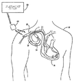
図1は、本発明に従って用いられるようになっている埋め込み可能医療デバイスシステムの図である。図1に示される医療デバイスシステムは、患者12に埋め込まれている埋め込み可能デバイス(IMD)10(たとえば、ペースメーカ)を含む。デバイス10は、気密封止された生物学的に不活性の外部ケーシング内に収容され、ケーシングそのものは導電性であり、ペーシング/検知回路内の不関電極としての役割を果たすことができる。図1においてまとめて参照符号14で特定される、1つ又は複数のペースメーカリード線が、従来どおりにIMD10に電気的に接続され、静脈18を介して、患者の心臓16の中まで延在する。リード線14の概ね遠位端付近には、心臓電気信号を受信し、且つ/又は心臓16に電気的なペーシング刺激を送出するための1つ又は複数の露出した導電性電極が配置される。心臓16の心房内及び/又は心室内にその遠位端が位置するようにリード線14を埋め込むことができる。
FIG. 1 is a diagram of an implantable medical device system adapted for use in accordance with the present invention. The medical device system shown in FIG. 1 includes an implantable device (IMD) 10 (eg, a pacemaker) that is implanted in a
本明細書において、本発明をペースメーカを含む一実施形態で説明するが、本発明が、有利には、多数の他のタイプの埋め込み可能医療デバイスシステムと共に、また、実際には、埋め込み可能カーディオバータ−ディフィブリレータ(ICD)等で起こる場合があるような、2腔ペーシング能力と共に、好ましい心房ベースペーシングモードを提供することが望ましい任意の応用形態において実施することができることを当業者は理解するであろう。さらに、本発明は、有利には、2心室ペーシング(bi−V)モードを提供するデバイスで実施することができる。心臓の左右の心室をペーシングし検知する、心不全患者の心機能を改善するためのbi−V心臓ペーシングシステムは、米国特許出願公開第2003/0083700号(その内容は参照により本明細書に援用される)に記載される。 Although the present invention is described herein in an embodiment that includes a pacemaker, the present invention is advantageously used with many other types of implantable medical device systems and, in practice, an implantable cardioverter. -Those skilled in the art will appreciate that it can be implemented in any application where it is desirable to provide a preferred atrial-based pacing mode with a dual chamber pacing capability, such as may occur in a defibrillator (ICD), etc. I will. Furthermore, the present invention can be advantageously implemented with devices that provide a two ventricular pacing (bi-V) mode. A bi-V cardiac pacing system for improving cardiac function in heart failure patients that paces and senses the left and right ventricles of the heart is disclosed in US Patent Application Publication No. 2003/0083700, the contents of which are incorporated herein by reference. ).
また図1には、アップリンク通信チャネル及びダウンリンク通信チャネルを介して、埋め込み可能デバイス10と非侵襲的に通信するための外部プログラミングユニット20も示される。従来の医療デバイスプログラミングシステムに従って、埋め込み可能デバイス10とプログラマ20との間の双方向通信を容易にするために、プログラミングユニット20にプログラミングヘッド22が関連付けられる。プログラマ20の一例は、米国特許第5,345,362号(参照により本明細書に援用される)に記載されている。
Also shown in FIG. 1 is an
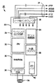
図2は、デバイス10を構成する電子回路機構のブロック図である。図2に見られるように、デバイス10は、デバイスのペーシング及び検知機能を制御するメインの刺激制御回路20を備える。刺激制御回路20に関連する回路要素は、たとえば、米国特許第5,052,388号(その内容は参照により本明細書に援用される)に開示されるものによる従来の設計とすることができる。刺激制御回路20は、センス増幅器24、刺激パルス(ペーシング)出力回路26、水晶クロック28、ランダムアクセスメモリ・読み出し専用メモリ(RAM/ROM)ユニット30、及び中央処理装置(CPU)32を含んでもよく、これら全ては当技術分野で既知である。デバイス10はまた、外部プログラマ/制御ユニット20と通信することができるように、テレメトリ回路34を含んでもよい。
FIG. 2 is a block diagram of an electronic circuit mechanism constituting the
引き続き図2を参照すると、図1を参照して既に述べたように、デバイス10は、1つ又は複数のリード線(lead)14と結合し、リード線は、埋め込まれると、デバイス10の埋め込み部位と患者の心臓16との間に経静脈的に延びる。物理的には、リード線14とデバイス10の種々の内部部品の間の接続は、図1に示す従来のコネクタブロックアセンブリ11によって容易に行われる。
With continuing reference to FIG. 2,
リード線の導体とデバイス10の内部電気部品の電気的な接続は、リード線インタフェース回路19によって容易に行うことができ、リード線インタフェース回路19は、マルチプレクサのように機能して、たとえば、心房先端電極導体ATIP及び心房リング電極導体ARING、並びに、心室先端電極導体VTIP及び心室リング電極導体VRINGを含む、リード線14の種々の導体と、デバイス10の個々の電気部品との間での必要な接続を選択的且つ動的に確立する。明確にするために、リード線14とデバイス10の種々の部品との間の特定の接続は図2には示されないが、たとえば、リード線14は、一般的なやり方に従って、直接的か又は間接的に、センス増幅器(検知回路)24及び刺激パルス出力回路26に必ず結合され、それにより、心臓電気信号が、センス増幅器24に伝達され、また、刺激パルスが、リード線14を介して心組織に送出されることが当業者に明らかになるであろう。同様に、たとえば、高電圧刺激パルスからデバイスの検知回路を保護するための、埋め込み式デバイスに一般的に含まれる保護回路要素は図2に示されない。
Electrical connection between the lead conductor and the internal electrical components of the
既に述べたように、刺激制御回路20は、市販のプログラム可能なマイクロプロセッサ又はマイクロコントローラとすることができるが、本発明では専用集積回路である中央処理装置(CPU)32を含む。CPU32と刺激制御回路20の他の部品との間の特定の接続は図2に示されないが、CPU32は、RAM/ROMユニット30に記憶されたプログラミングの制御下で、刺激パルス出力回路26及びセンス増幅器24のタイミングをとった動作を制御するように機能することができる。
As already mentioned, the
引き続き図2を参照すると、水晶発振器(水晶クロック)28、現在の好ましい実施形態では、32,768Hz水晶制御式発振器は、刺激制御回路20に主タイミングクロック信号を供給する。この場合も、こうしたクロック同期(clocking)信号が、デバイス10の種々のタイミング同期(timed)部品(たとえば、マイクロプロセッサ32)にそこを通じて供給されるラインは、明確にするために、図2から省かれる。さらに、図2に示すデバイス10の種々の部品は、デバイス10の密閉格納器内に収容される電池(図示せず)によって駆動されることが理解される。CPU32が出す信号の制御下で心臓刺激を生成するように機能する刺激パルス出力回路26は、任意の適したタイプとすることができる。この場合も、当業者は、本発明を実施する目的に適すると思われる、多くの種々のタイプの従来技術のペーシング出力回路の中から選択することができると考えられる。
With continued reference to FIG. 2, a crystal oscillator (crystal clock) 28, in the presently preferred embodiment, a 32,768 Hz crystal controlled oscillator provides a main timing clock signal to the
従来の設計とすることができるセンス増幅器24は、リード線14から心臓電気信号を受信し、こうした信号を処理して、心房収縮(P波)及び心室収縮(R波)を含む特定の心臓電気事象の発生を反映する事象信号を導出するように機能する。デバイス10の同期刺激動作の制御に用いるために、センス増幅器24は、これらの事象指示信号をCPU32に提供する。さらに、これらの事象指示信号は、医師又は臨床医に対して視覚的に表示するために、アップリンク送信を介して、外部のプログラミングユニット20に伝達することができる。デバイス10は、多数の他の部品及びサブシステム、たとえば、活動センサ及び関連する回路要素を含んでもよいことを当業者は理解するであろう。
A
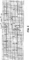
デバイス10は、心房ベースペーシングモードを提供するように適合することができる。適した心房ベースペーシングモードは、ADI/Rモード及びAAI/Rモードを含む。一部の実施形態では、デバイス10は、不必要な心室ペーシングを制限するために、心房ベースペーシングモードで動作するように偏りがある。図3は、AAI/R動作のラダー図である。NBGコードによって、第1の位置の文字(A)は、ペースメーカ(又は、他の埋め込み式デバイス)が、心房検知事象のないときに心房をペーシングすることを意味する。第2の文字(D)は、ペースメーカが、2腔で、すなわち、心房腔と心室腔の両方で検知することを意味する。第3の文字(I)は、いずれかの腔における検知によって、ペーシングは、その特定の腔において禁止されることを意味する。最後の文字、Rは、デバイスが、レート応答性である、すなわち、圧電結晶、加速度計等の人工センサ、換気量等に応答して、心房レートを変えることを意味する。
AAI/Rモードの動作は、以下の通りに、ラダー図に示される。心房ペースによる(又は検知)事象1は、ブランキング期間4と、それに続く、心房感度の自動調整(図示せず)を始動する。検知回路(図2を参照されたい)は、心室検知事象2が、起こったか否か、また、いつ起こったかを確定する。検出された場合、CPU32(タイミング回路要素:図2を参照されたい)は、VA間隔9を始動する。他のタイミング、ブランキング期間、及び不応期は、以下の目的に役立つ。プログラム可能心室ブランキング期間8は、「クロストーク」と呼ばれることがある、心室チャネルに関する心房ペース1の検知を防止する。心室検知事象2は、心室後心房ブランキング(post ventricular atrial blanking)(PVAB)期間6(たとえば、120ミリ秒)と、それに続く、心房感度の自動調整を開始する。PVAB6は、「遠方界R波検知」と呼ばれる、心房チャネルに関するR波又はT波の検知を防止するのに役立つ。心室検知事象2はまた、心室ブランキング7(たとえば、100ミリ秒)と、それに続く、心室感度の自動調整を開始する。この期間は、心室出力パルス又は心室脱分極自体の検知を防止するのに役立つ。再分極又はT波3は、R波2に続く。検知回路(図2を参照されたい)によって検出される心室事象2は、タイミング回路要素に信号を送出して、次の心房ペーシング周期をもたらすVA間隔9を開始する。いくつかのR−R間隔が、図3に示される。 The operation of the AAI / R mode is shown in the ladder diagram as follows. Atrial pace (or detection) event 1 triggers a blanking period 4 followed by automatic adjustment of atrial sensitivity (not shown). A sensing circuit (see FIG. 2) determines whether and when a ventricular sensing event 2 has occurred. If detected, the CPU 32 (timing circuit element: see FIG. 2) starts the VA interval 9. Other timing, blanking periods, and refractory periods serve the following purposes: Programmable ventricular blanking period 8 prevents detection of atrial pace 1 for ventricular channels, sometimes referred to as “crosstalk”. Ventricular sensing event 2 begins a post ventricular atrial blanking (PVAB) period 6 (eg, 120 milliseconds) followed by automatic adjustment of atrial sensitivity. PVAB 6 helps prevent detection of R-waves or T-waves for the atrial channel, referred to as “far-field R-wave detection”. Ventricular sensing event 2 also initiates ventricular blanking 7 (eg, 100 milliseconds) followed by automatic adjustment of ventricular sensitivity. This period helps to prevent detection of ventricular output pulses or ventricular depolarization itself. A repolarization or T wave 3 follows the R wave 2. Ventricular event 2 detected by the sensing circuit (see FIG. 2) initiates a VA interval 9 that sends a signal to the timing circuit element resulting in the next atrial pacing cycle. Several RR intervals are shown in FIG.
心房ベースペーシングモードは、一般に、完全なAV伝導を完全に、又は、或る程度有する洞不全患者に関して主に使用することができる。比較的信頼性の高い、完全なAV伝導が存在する場合、ペースメーカは、心房ベース(たとえば、ADI/R)動作/モードを維持する。検知心室事象は、大多数の心周期(すなわち、PQRST)で起こるであろう。図4は、患者が、1心周期又は数心周期にわたって一過性AVブロックを生じる場合、何が起こることになるかを教示する。 The atrial-based pacing mode can generally be used primarily for sinus insufficiency patients who have complete or some degree of complete AV conduction. If there is relatively reliable, complete AV conduction, the pacemaker maintains atrial-based (eg, ADI / R) operation / mode. A sensed ventricular event will occur in the majority of cardiac cycles (ie, PQRST). FIG. 4 teaches what will happen if a patient develops a transient AV block over one or several cardiac cycles.
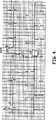
AV伝導の信頼性がなくなる場合、デバイス10は、2腔ペーシングモードへ切換わるようになっている。2腔ペーシングモードの例は、DDD/Rペーシングモード及びDDI/Rペーシングモードを含む。図4は、患者がAV伝導の一過性喪失を経験する場合の、心室バックアップ動作のラダー図である。心室バックアップ動作の目的は、心室サポートを維持する(すなわち、心室収縮間の間隔が、1周期だけに制限されるように、心室がペーシングされることを確実にする)ことである。簡潔に述べると、一部の実施形態では、埋め込み式デバイスは、少なくとも1心周期にわたるAV伝導の一過性喪失に応答して、心房ベースペーシングモードから2腔ベースペーシングモードへモード切換えを行う。
If the AV conduction is unreliable, the
DDI/Rのタイミングは、以下の通りにすることができる。DDI/Rモード(第4のペーシング周期、DDI/Rと表示される)において、第2の心房ペースによる事象と第3の心房ペースによる事象との間にPVCが存在するため、AV間隔5は、ペースによるP波に続く短い期間(たとえば、80ミリ秒)に設定される。この短いAV間隔5の目的は、ペースによるR波13において最高点に達する心室ペーシングパルスと、以前のペースによる心房事象からの遅延した伝導を有する任意の可能性のある内因性R波との間の競合を抑制することを意図される。
The DDI / R timing can be as follows. In DDI / R mode (labeled 4th pacing period, DDI / R), there is a PVC between the second atrial pace event and the third atrial pace event, so the
こうした内因性R波の存在を仮定すると、心室出力パルスのタイミングは、通常、内因性の伝導R波の絶対不応期内に入る心室ペーシングパルスをもたらすことになり、擬似融合拍動(psuedo-fusion beat)(図示せず)が生じる。心室ペーシングパルスが、一般に「Tに関するペーシング(pacing on T)」現象と呼ばれる、心室の相対的不応期内に入る場合には、この動作は、心室頻脈の開始を防止することを意図される。 Assuming the presence of such intrinsic R-waves, the timing of the ventricular output pulse will usually result in a ventricular pacing pulse that falls within the absolute refractory period of the intrinsic conducted R-wave, and a pseudo-fusion pulse (psuedo-fusion beat) (not shown) occurs. If the ventricular pacing pulse falls within the relative refractory period of the ventricle, commonly referred to as the “pacing on T” phenomenon, this action is intended to prevent the onset of ventricular tachycardia. .
上記に関し、本発明の一部の実施形態では、Aペース(AP)が、ほぼ4よりも多い脱分極事象(たとえば、連続拍動)について、先行するVセンス(VS)に侵入する場合(たとえば、300ミリ秒以内)、ペーシングレートが減少する。事実上、これは、動的な上限センサレートを生成する。比較的短いVS−AP間隔から生じる場合がある、可能性のある不利な患者症状に対処するために、MVPモダリティは、VS事象後に、或る所定の間隔が終了するまで、予定されたAP事象が遅延されるように動作することができる。MVPモダリティのこの態様は、VSに続くAP事象に基づいていること以外は、上限トラッキングレート(UTR)ホールドオフ又は非競合的心房ペーシング(NCAP)ホールドオフにある程度似ている。これによって、心房が、意図されるよりもわずかに低いレートでペーシングされることになり、いわゆる、心房過剰駆動ペーシングアルゴリズムの場合に存在することが知られている問題を生じる場合がある。一部の実施形態では、MVPモダリティのこの態様は、きわどいタイミングが必要とされるため、主にハードウェアで実施される。 With respect to the above, in some embodiments of the invention, when the A-pace (AP) penetrates the preceding V-sense (VS) for more than approximately 4 depolarization events (eg, continuous beats) (eg, , Within 300 milliseconds), the pacing rate is reduced. In effect, this generates a dynamic upper sensor rate. In order to deal with possible adverse patient symptoms that may result from a relatively short VS-AP interval, the MVP modality is responsible for scheduled AP events after a VS event until a given interval ends. Can be operated to be delayed. This aspect of the MVP modality is somewhat similar to upper tracking rate (UTR) hold-off or uncompetitive atrial pacing (NCAP) hold-off, except that it is based on the AP event following VS. This causes the atrium to be paced at a slightly lower rate than intended, which can cause problems that are known to exist in the case of the so-called atrial overdrive pacing algorithm. In some embodiments, this aspect of the MVP modality is implemented primarily in hardware because it requires critical timing.
図4のタイミングに関して続けると、ペースによるR波13は、心室ブランキング期間7を開始し、その後、心室感度の自動調整(図示せず)が続く。ペースによるR波13はまた、PVAB6を開始し、その後、心房感度の自動調整(図示せず)が続く。一過性のAVブロックが自己修正し、心室ペース(VP)に応答して検知R波が検出されると仮定すると、心房ベースペーシングモードは、図3に示すように、次のペースによるP波又は検知P波によって再開する。 Continuing with the timing of FIG. 4, the paced R wave 13 begins a ventricular blanking period 7 followed by automatic adjustment of ventricular sensitivity (not shown). The paced R wave 13 also initiates PVAB 6 followed by automatic adjustment of atrial sensitivity (not shown). Assuming that the transient AV block is self-correcting and a sensed R-wave is detected in response to the ventricular pace (VP), the atrial-based pacing mode is the next paced P-wave as shown in FIG. Or it restarts by the detection P wave.
図5は、患者が、2周期以上にわたって、AVブロックを生じる場合のペーシング動作を示すラダー図である。DDD/Rへのモード切り換えに続いて、VA間隔9はタイムアウトし、心房ペースによる事象1が生じる。本明細書において以下でさらに述べるように、生来のAV伝導を促進しようと試みて(すなわち、VP刺激を控える場合がある)、非常に長い(たとえば、400ミリ秒若しくは中央値V−V間隔のほぼ約70%まで、又はそれ以上の)AV間隔17を使用することができる。しかし、AV間隔17が、第1の周期(ADI/Rと表示される)に示すように、検知内因性R波によって中断されない場合、ペースメーカは、直ちに、DDD/Rモードに切り換わることができる。検知内因性R波が起こらない場合、デバイスは、心房ベースペーシングモード動作に復帰する。プログラムされたAV間隔を有するDDD/R動作は、本明細書においてさらに述べるように、検知内因性R波が検出されるまで持続する。DDI/Rへのモード切り換えは、心房頻脈が検出される場合に行うことができる。 FIG. 5 is a ladder diagram showing a pacing operation when a patient generates an AV block for two or more cycles. Following the mode switch to DDD / R, VA interval 9 times out and event 1 due to atrial pace occurs. As discussed further herein below, attempts to promote innate AV conduction (ie, may refrain from VP stimulation) and very long (eg, 400 ms or median VV intervals) An AV interval 17 (up to about 70% or more) can be used. However, if the AV interval 17 is not interrupted by the detected intrinsic R wave, as shown in the first period (labeled ADI / R), the pacemaker can immediately switch to DDD / R mode. . If no detected intrinsic R-wave occurs, the device returns to atrial-based pacing mode operation. DDD / R operation with a programmed AV interval lasts until a sensed intrinsic R wave is detected, as further described herein. The mode switching to DDI / R can be performed when an atrial tachycardia is detected.
本発明の一部の実施形態は、心房ベースペーシングモードでペーシングするように偏る。図6は、持続する2腔ペーシング動作中に心房ベースペーシングモード(たとえば、AAI/R)動作を回復しようとする周期的な試行を示す図である。述べたように、患者が、レート依存AVブロックと共に起こる場合があるような長期のAVブロックを生じる場合、又は、AV伝導が比較的信頼性がなくなる場合、DDD/Rモードは、持続する動作モードになる場合がある。こうした場合、デバイスは、プログラム可能な数のDDD/R周期後に、ADI/R1に復帰するようにプログラムすることができる。こうして、デバイスは、たとえば、心房ペース1に続く23において心室検知事象を探す。検知内因性R波が検出される場合、AAI/R動作が直ちに再開される。心室検知事象がない場合、デバイスは、図6Aに示すようにDDD/Rモードで動作し続ける。 Some embodiments of the invention are biased to pace in an atrial-based pacing mode. FIG. 6 is a diagram illustrating periodic attempts to restore atrial-based pacing mode (eg, AAI / R) operation during sustained two-chamber pacing operation. As noted, DDD / R mode is a sustained mode of operation if the patient produces long-term AV blocks that may occur with rate-dependent AV blocks, or if AV conduction is relatively unreliable. It may become. In such a case, the device can be programmed to return to ADI / R1 after a programmable number of DDD / R periods. Thus, for example, the device looks for a ventricular sensing event at 23 following atrial pace 1. When the detected intrinsic R wave is detected, the AAI / R operation is immediately resumed. In the absence of a ventricular sensing event, the device continues to operate in DDD / R mode as shown in FIG. 6A.
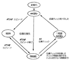
図7は、患者が心房頻脈(AT)又は心房細動(AF)を生じる場合のモードスーパバイザの図である。洞不全患者は、AT、心房粗動、又は心房細動のエピソードを有することが多い。これらのエピソード中に、ペーシング動作は、心室ペーシングレートが、高速心房レートに同期もせず、症状を引き起こすほどに緩徐でもないように設定されなければならない。好ましくは、ATエピソード中に、心房ベースペーシングが終了し、心室ペーシングサポートを提供するために、レート応答が使用可能になっている非トラッキング(すなわち、DDI/R)ペーシングモードが使用される。 FIG. 7 is a diagram of a mode supervisor when a patient experiences atrial tachycardia (AT) or atrial fibrillation (AF). Sinus failure patients often have episodes of AT, atrial flutter, or atrial fibrillation. During these episodes, the pacing action must be set so that the ventricular pacing rate is neither synchronized to the fast atrial rate nor slow enough to cause symptoms. Preferably, during an AT episode, a non-tracking (ie, DDI / R) pacing mode with rate response enabled is used to terminate atrial-based pacing and provide ventricular pacing support.
図4では、デバイスは、心房ベースペーシングモードで動作している間、捕捉の一過性喪失に応答してDDI/Rモードへ切換わることができることが留意された。DDI/Rモードはまた、高速心房レートに対する心室同期を可能にすることもなく、心室ペーシングレートがプログラムされた下限レート未満に下がることもさせないため、心房頻脈の存在下でのペーシングに好適である。したがって、心房頻脈が起こるとき、心室事象が伝導されない高速心房検知事象は、心室タイミングに影響を及ぼさない。心室事象が存在しないため、動作は、DDI/Rモードに直ちに切り換わる。AT又はAFの存在下で、V−V間隔は、DDI/Rモードにおいて、ペースによるR波が、プログラムされた下限レート、又はセンサが指示したレートのうちの速い方で起こるようにタイムアウトすることができる。図7に示す動作は、AT又はAFが持続する限り続く場合がある。ATの終了時に、心臓がATからどのように回復するかに応じて、好ましいAAI/Rが、図3又は図6に示すように再開することができる。ATが急に終了する場合、心房ベースペーシングモードの迅速な回復が起こる場合がある(図3を参照されたい)。しかし、ATが、ゆっくり「クールダウン(cool down)」する場合、図6に示すように、心房ベースペーシングを回復しようとする周期的な試行によって、DDD/Rペーシングの期間が存在する場合がある。 In FIG. 4, it was noted that the device can switch to DDI / R mode in response to a transient loss of capture while operating in atrial-based pacing mode. The DDI / R mode is also suitable for pacing in the presence of atrial tachycardia because it does not allow ventricular synchronization for fast atrial rates and does not allow the ventricular pacing rate to drop below the programmed lower rate. is there. Thus, when an atrial tachycardia occurs, a fast atrial detection event in which the ventricular event is not conducted does not affect ventricular timing. Since there is no ventricular event, operation immediately switches to DDI / R mode. In the presence of AT or AF, the VV interval will time out in DDI / R mode so that the paced R wave occurs at the faster of the programmed lower rate or the rate indicated by the sensor. Can do. The operation shown in FIG. 7 may continue as long as AT or AF continues. At the end of the AT, depending on how the heart recovers from the AT, the preferred AAI / R can resume as shown in FIG. 3 or FIG. If the AT ends abruptly, a rapid recovery of the atrial-based pacing mode may occur (see FIG. 3). However, if the AT slowly “cools down”, there may be periods of DDD / R pacing due to periodic attempts to restore atrial-based pacing, as shown in FIG. .
心房ベースペーシングモードと2腔ベースペーシングモードとの間で切換えるのに有用なモードスーパバイザの一実施形態は、図8に包括的に示される。一部の実施形態では、モードスーパバイザは、モード変更に関連する広範な動作を制御する。モードスーパバイザは、患者の房室状態を監視し、必要であれば、2腔ペーシングモードへの持続するモード切換えを起動することによって介入することができる。一部の実施態様によれば、モードスーパバイザは、許容可能な(又は、「比較的信頼性の高い」)AV伝導状態を、許容できない(又は、「比較的信頼性のない」)AV伝導状態から見分けるための臨界AV伝導受容比(critical AV conduction acceptance ratio)の定義を使用するウェンケバッハパターンに従って信頼性のないAV伝導を定義する。たとえば、全ての4つの生理的心房事象について少なくとも3つの心室事象が存在する限り、4:3のAV伝導受容比によって、好ましい心房ベースペーシングモード動作が持続することが可能になる。AV伝導が、A事象とV事象の比が所定の受容比よりも低くなるように弱まる場合には、2腔ペーシングへの持続する切換えが起こる。非生理的であると分類された心房事象は、A:V比の計算において反映されなくてもよい。それにより、2腔ペーシングへの不適切なモード切り換えは、頻繁な非伝導性心房期外収縮(PAC)の存在下で回避される。 One embodiment of a mode supervisor useful for switching between an atrial based pacing mode and a dual chamber based pacing mode is shown generally in FIG. In some embodiments, the mode supervisor controls a wide range of operations associated with mode changes. The mode supervisor can intervene by monitoring the patient's atrioventricular condition and, if necessary, initiating a continuous mode switch to the dual chamber pacing mode. According to some embodiments, the mode supervisor can accept an acceptable (or “relatively reliable”) AV conduction state and an unacceptable (or “relatively unreliable”) AV conduction state. Define unreliable AV conduction according to the Wenkebach pattern using the definition of critical AV conduction acceptance ratio to distinguish from For example, as long as there are at least three ventricular events for all four physiological atrial events, a 4: 3 AV conduction acceptance ratio allows the preferred atrial-based pacing mode operation to persist. If AV conduction weakens such that the ratio of A event to V event is lower than a predetermined acceptance ratio, a continuous switch to dual chamber pacing occurs. Atrial events classified as non-physiological may not be reflected in the calculation of the A: V ratio. Thereby, inappropriate mode switching to dual chamber pacing is avoided in the presence of frequent non-conducting pre-atrial contractions (PACs).
信頼性のないAV伝導の存在時に2腔ペーシングを起動すると、モードスーパーバイザは直ちに、心房ベースペーシングモードを回復しようと試みることができる。AV伝導疾患は通常徐々に進行し、疾患進行の早期の段階において、高度ブロックの短い徴候が予想されることがわかっているので、モードスーパーバイザは、新たに開始された2腔ペーシングの、ほんの短期のエピソード後に、心房ベースペーシングを回復しようと試みるであろう。好ましい動作によれば、DDD/Rペーシングからわずかな期間(たとえば、1分)の2腔ペーシングの後に、完全なAV伝導を明らかにすると共に心房ベースペーシングを回復しようとする最初の再試行が生じる。心房ベースペーシングの回復が失敗する場合には、たとえば、2分、4分、8分、16分及び32分等の期間において、その後、たとえば、1時間、2時間、4時間、8時間、12時間及び24時間において、再試行が行われる。もちろん、周期的及び非周期的に(そして、ローカル及びリモートで臨床医又は患者によって起動される心房ベースペーシングの開始時に)、他のタイミングシーケンスが用いられることができる。 When activating dual chamber pacing in the presence of unreliable AV conduction, the mode supervisor can immediately attempt to recover the atrial-based pacing mode. Since AV conduction disease usually progresses gradually and we know that early signs of advanced block are expected in the early stages of disease progression, mode supervisors will only need a short period of newly initiated dual-chamber pacing. After an episode, you will try to restore atrial-based pacing. According to the preferred operation, after a short period (eg, 1 minute) of two-chamber pacing from DDD / R pacing, the first retry to reveal complete AV conduction and restore atrial-based pacing occurs. . If atrial-based pacing recovery fails, for example in a period of 2 minutes, 4 minutes, 8 minutes, 16 minutes and 32 minutes, then for example 1 hour, 2 hours, 4 hours, 8 hours, 12 Retries occur at time and 24 hours. Of course, other timing sequences can be used periodically and aperiodically (and at the start of atrial-based pacing initiated by the clinician or patient locally and remotely).
完全なAV伝導を探索し、ADI/Rを回復するのに使用されるアルゴリズムは、こうした伝導を検出するのに有用な、いずれのアルゴリズムであってもよい。たとえば、デバイスは、2腔ペーシング動作中に心室ペース刺激を控えることができる。心室ペーシングをその間控えた生理的心房事象に、心室センスが続く場合、心房ベースペーシングが再開される。そうでなければ、2腔ペーシングは、予定に従って、又は、(先に指定した)手作業による起動によって、その後の再試行と共に継続する。別の例として、完全なAV伝導についてのデバイス探索は、2腔ペーシング中のAV遅延を、予め指定したAV伝導探索間隔(AVCI)まで延ばすことを含む。たとえば、400ミリ秒のAVCIの場合、AV遅延は、生理的心房事象(検知又はペースによる)に続く400ミリ秒まで延ばされる。AV間隔が心室センスによって中断され、それにより、2腔動作における心室ペースが妨げられる場合、モードスーパバイザは心房ベースペーシングへ復帰する。そうでなければ、心室ペースはAVCI間隔の終了によって送出され、2腔ペーシング動作は、上述した予定に従って(又は、手作業による起動によって)、再試行と共に再開する。これらのAV伝導探索法の間に伝導及び心室ペーシングが失敗する場合、ペースメーカ媒介頻脈を始動する逆行性伝導の可能性を警戒するために、AVCIに続いて、長い心室後心房不応期(post-ventricular atrial refractory period)(PVARP)が起動され得る。 The algorithm used to search for complete AV conduction and recover ADI / R can be any algorithm useful for detecting such conduction. For example, the device can refrain from ventricular pace stimulation during a dual chamber pacing operation. If the ventricular sense is followed by a physiological atrial event with no ventricular pacing in between, atrial-based pacing is resumed. Otherwise, dual chamber pacing continues with subsequent retries on schedule or by manual activation (as specified above). As another example, device search for full AV conduction includes extending the AV delay during two-chamber pacing to a pre-specified AV conduction search interval (AVCI). For example, for a 400 ms AVCI, the AV delay is extended to 400 ms following a physiological atrial event (due to detection or pace). If the AV interval is interrupted by ventricular sense, thereby impeding the ventricular pace in dual chamber operation, the mode supervisor returns to atrial-based pacing. Otherwise, the ventricular pace is delivered at the end of the AVCI interval, and the dual chamber pacing operation resumes with a retry according to the schedule described above (or by manual activation). If conduction and ventricular pacing fails during these AV conduction search methods, AVCI is followed by a long post-ventricular atrial refractory period (post) to warn of the possibility of retrograde conduction that triggers pacemaker-mediated tachycardia. -ventricular atrial refractory period (PVARP) can be activated.
デバイス10はまた、心房捕捉管理(ACM)を行うようになっている。心房が、ペーシングされる主要な腔であり得るため、心房の捕捉を確実にすることは、上述したデバイスにおいて特に有用である。一般に、心房捕捉を確定するために、2つの異なる試験、すなわち、心房腔リセット(ACR)試験及び房室伝導(AVC)試験が実施される場合がある。患者が、通常、洞不全とAVブロックとの両方を有しない点で、ACRは、AVC方法に対して相補的である。ACR及びAVC閾値試験中に、順次探索(sequential search)を使用して、捕捉が喪失されるか、又は、獲得される時点を計算することができる。一部の実施形態では、患者の調律のランダムな変化のために起こる可能性がある単一事例によるエラーをなくすことによって捕捉検出方法の精度を上げるために、捕捉及び捕捉の喪失は、連続する3つの試験ペースのうちの2つの試験ペースにおいて同じペーシング値で評価される。
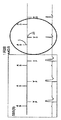
図9Aは、ACR中のAPt(心房ペーシング試験)パルスによる捕捉を示すECGトレーシング及びEGMトレーシングの表示である。EGM42は、ペーシング電極レベル上で見ることができる心房脱分極を表示する。EGM42上の脱分極信号の差は、心房センス信号47と早期APtパルス48の上に現れる波形において容易に見られる。ECGトレーシング44は、異なるベクトルからのものであり、一般に、12誘導ECGトレーシングにおいて見出されるベクトルを代表する。ECGトレーシング44に関して、2つの間隔が示される。間隔46は、APtパルス48の前の基準心房間隔であり、間隔50は、早期APtパルス48後に起こる「リターン」心房間隔である。
FIG. 9A is a representation of ECG and EGM tracings showing capture by APt (atrial pacing test) pulses during ACR. The
ACR中に、比較的安定した洞駆動調律が存在する。ACRは、「安定した」洞調律を有する患者に使用されることを意図される。すなわち、ACRが実施される前に、一連の安定した周期が検出されるべきである。より具体的には、これらのAS−AS周期は、図9A〜図10において、間隔46として表される。実際には、ACRを続ける前に、いくつかのこれらの周期が観測されるべきである。たとえば、3〜10の連続する安定した周期は、一般に、全体の安定性を指示し、APtパルス48が始動されることを可能にする。ACRにて、APtパルス48が閾値以下である場合、その後のAS47は、以前の安定した間隔で起こる(図9Bを参照されたい)。APtパルス48が閾値を超える場合、APtパルス48は、洞を捕捉し、リセットし、正常間隔でのASは存在しない。
There is a relatively stable sinus drive rhythm during ACR. ACR is intended to be used for patients with “stable” sinus rhythm. That is, a series of stable periods should be detected before ACR is performed. More specifically, these AS-AS periods are represented as
A−A間隔46は、一連の安定した心房調律間隔の最後のA−A間隔を表す。図示する例では、955ミリ秒のA−A間隔46と1038ミリ秒のA−A間隔50は、ほぼ同じ持続期間を有する。APtパルス48による捕捉後、リターンA−A間隔50は、通常、基準A−A間隔46よりもわずかに長い。これは、心房脱分極波(通常、心房付属器内に置かれる心房電極によって始動される)が移動し、SA結節をリセットするのにかかる時間に、次の洞始動波がSA結節から心房電極へ移動するのにかかる時間を加えた時間による。前の数秒の間に、順次スイープ動作は、48にて心房を捕捉するまで、APtパルスの出力を増加させた。この時、安定した心房調律もまた中断されて、再び間隔50の終了時に再開されるだけである。早期APtパルスによるこの中断と、それに続く、前のレートでの、又は、前のレートに近い、前の安定した調律の再開は、心房を捕捉するのに必要とされる心房出力パルスの大きさを決定する。
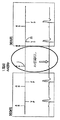
図9Bは、ACR中の、APtパルス48bによる補足の喪失(LOC)を示すECGトレーシング及びEGMトレーシングの表示である。図9Aと同様に、間隔46bは、安定した心房調律を表す。図示する例では、A−A間隔46bは、ほぼ同じ持続期間(それぞれ、1027ミリ秒、1027ミリ秒、及び1000ミリ秒)を有する。しかし、APtパルス48bは、心房を捕捉するのに失敗する。したがって、安定した心房調律が、中断することなく継続する。アルゴリズムは、安定した調律における中断の欠如を認識し、後続の試験シーケンスについて心房出力を増加させるために、順次スイープを「指令する」。
FIG. 9B is an ECG and EGM tracing display showing loss of supplementation (LOC) due to
図10は、図9A及び図9Bに相当する種々の間隔を例示するタイミング図である。間隔46は、心房基準間隔、すなわち、心房センスによって開始し、心房センスによって終了する間隔に相当する。APtパルス48は間隔49で起こり、その大きさに応じて、心房を捕捉する場合もあり、又は、しない場合もある。一部の実施形態では、安定した心房捕捉が起こったというアルゴリズムを満たすために、同じ大きさのAPtパルスによる、こうした3つの連続する試験周期のうちの2つの試験周期が、心房を捕捉しなければならない。
FIG. 10 is a timing diagram illustrating various intervals corresponding to FIGS. 9A and 9B. The
心房が、APtパルス48によって捕捉されず、リセットされない場合、AS(予測)52は、支配的な洞レート(たとえば、60bpm)で起こる。APtパルス48からAS(予測)までの間隔、すなわち(間隔58+間隔54)の時間は短くなる。一方、APtパルス48から次の心房センスまでの間隔、すなわち、図10の端にある、APt48からAS47までの時間(間隔50)が長い場合、APtパルス48による心房の捕捉が明らかに起こっている。
If the atrium is not captured and reset by the
上記に加えて、アルゴリズムは、患者の洞調律の正常な生理的変動を考慮することができる。この変動に対処するために、間隔54は、この例では、60bpmから70bpmを引いた値(又は、1000ミリ秒から857ミリ秒を引いた値)であり得る、前よりも10bpmだけ速いAS−AS間隔を開始する。間隔54は、「負の」検知間隔として記述されてもよく、一般に、少なくとも、或る生理的許容度(たとえば、約50ミリ秒)である。一方、間隔56は、「正の」検知間隔として記述されてもよく、一般に、「負の」間隔と同じ持続期間である。間隔54と56とをまとめて「LOC検出窓」と呼ぶことができる。LOC検出窓内で検知される心房事象は、心房試験ペースが心房を捕捉しなかったことを意味する。結果として、AS(予測)事象52が、LOC検出窓内で起こる(且つ、3つのルールのうちの2つのルールが満たされる)場合、心房パルス出力は、次の順次スイープで増加する。間隔58は、心房ペースに続くブランキング間隔であり、ブランキング間隔中、心房センス増幅器は、心房内の電気活動を一切検知することができない。APtパルス48によって開始される間隔50は、持続期間がおよそ間隔46に対応し、心房をリセットした心房捕捉を表す(この時、心房リード線から放出されるペーシングパルスが洞結節へ移動し、洞結節から発生する後続の心房センスが心房リード線まで移動するのに必要とされる時間に相当する心房内伝導遅延時間のために、おそらく、或る程度の時間延長が存在する)。その後、周期が、再び開始する。3つの試験ペースのうちの少なくとも2つの試験ペースが捕捉したとき、心房調律の安定性は、別のAPtパルス48が送出されるか、又は、ACRが終了する前に、再び確立されなければならない。一部の実施形態では、3つの試験ペースのうちの少なくとも2つの試験ペースが心房を捕捉し、且つ、閾値が求められると、安全域を計算し、発効させることができる。
In addition to the above, the algorithm can take into account normal physiological variations in the patient's sinus rhythm. To deal with this variation, the
図11は、AVC動作の一実施形態を説明する全体タイミング図である。AVCにおいて、通常、安定した心房ペース−心室センス(AP−VS)調律が存在する。閾値以下の心房試験ペースは心房を捕捉せず、結果として、AP−VS調律は中断される。試験ペースは、心房閾値を越える場合、心房を捕捉し、早期AV伝導及びVSをもたらし、VSは、80ではなく78にある。早期伝導は、AVCにおける捕捉のマーカである。AVCは、良好なAV伝導を有する患者のために意図される。通常、これらの患者は、とりわけ、洞結節障害(SND)又は洞不全症候群(SSS)のためにペースメーカを受け入れる。一部の実施形態では、AVC方法を実行するために、CRT治療を一時的に中止することができ、且つ/又は、プログラムされたAV間隔を一時的に延長することができる。さらに、たとえば、心室センス反応(VSR)等のアルゴリズムを使用して、所望であれば、心室が検知された後に心室ペースをトリガーすることができる。 FIG. 11 is an overall timing diagram illustrating one embodiment of the AVC operation. In AVC, there is usually a stable atrial pace-ventricular sense (AP-VS) rhythm. An atrial test pace below the threshold does not capture the atrium, and as a result, the AP-VS rhythm is interrupted. If the test pace exceeds the atrial threshold, it captures the atrium, resulting in early AV conduction and VS, with VS at 78 instead of 80. Early conduction is a marker of capture in AVC. AVC is intended for patients with good AV conduction. Usually, these patients accept pacemakers for, inter alia, sinus node disorder (SND) or sinus failure syndrome (SSS). In some embodiments, CRT therapy can be temporarily suspended and / or the programmed AV interval can be temporarily extended to perform the AVC method. Further, for example, an algorithm such as a ventricular sense response (VSR) can be used to trigger the ventricular pace after the ventricle is detected, if desired.
さらに、図11を参照すると、間隔70は、間隔76と共に、AVC動作以外の時点で見られる安定したAP−VC調律を明示する、プログラムされたAP−AP間隔である。間隔72は、プログラムされた/計算された出力設定のAPで始まるが、APtパルス66において早期に終了する。AVCにおいて、順次スイープは、最大の大きさ(捕捉を維持する大きさ)で開始し、より小さい大きさ(捕捉を喪失する大きさ)の順次スイープに減分されることができ、(捕捉を喪失する)低い心房出力で開始し、捕捉が回復されるまで出力を増分する心房閾値探索方法が可能であるが、閾値未満の測定及び閾値を超える測定値が、閾値を求めるために必要とされる。AVCはまた、APtパルス66がわずかに早期であり、且つ、捕捉を維持する可能性が高いようにタイミングをとり、その後、最終的に捕捉を喪失させるために、これらの試験パルスの大きさをゆっくりと低減させる。間隔74は、早期性の尺度を示し、心房バックアップペーシングパルス68で終了する。早期性間隔74は、通常、50ミリ秒〜100ミリ秒の範囲である。バックアップパルス68は、実際には、過剰駆動AP−AP間隔で起こる。VS78が起こる場合、ソフトウェア/アルゴリズムは、APtパルス66が心房を捕捉しており、心房捕捉を喪失するためにAPtパルス66のさらなるエネルギー低減が必要とされると確定する。パルスの大きさの、こうしたさらなる低減は、VS事象が80で起こるまで、すなわち、安定した調律中に前に観測されたAP−VS時間が経過するまで行われる。これが起こると、アルゴリズムは、APtパルス66が捕捉を喪失したと確定する。捕捉の喪失が、3つの中の少なくとも2つの連続する複合波(complex)内で起こる場合、アルゴリズムは最後の捕捉出力設定に戻り、この設定を使用して安全域を計算する。
Still referring to FIG. 11,
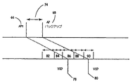
図12は、APtパルス66が心房を捕捉するときのAVC動作の詳細図である。APtパルス66は放出され、早期性間隔74を開始し、予定された心房ペーシングパルス(本明細書では、APバックアップ(Backup)68と呼ぶ)の放出をもたらす。AP バックアップ68の目的の1つは、APtパルス66が捕捉を喪失するときに、捕捉を確保することである。動作が成功するために、患者が安静にする必要はない。ACRと同様に、AVC動作は、APtパルス66の代わりに、心房ペーシングの増加中に見られるAV伝導延長という現象を誘発せず、VS80において、偽陰性心室センスを生成しない、(閾値を超える出力の)コントロールペースを周期的に放出してもよい。VS78がコントロールペースに関して発生する場合、AV伝導延長は起こらず、一方、コントロールペースに関するVS80の発生は、コントロールペースのわずかな早期性によるAV伝導延長を示す。コントロールペースは、偽陰性、すなわち、APtパルス66は心室に対する伝導の欠如のために心房捕捉を実際には喪失したという結論をもたらす偽陰性をなくすことを意図される。
FIG. 12 is a detailed view of the AVC operation when the
間隔82は、心房バックアップペース68の後に、心室センス増幅器がブランキングされる期間である。これは、心室回路要素に応じて変わる。間隔84中に起こるいずれの心室事象も、クロストークによる可能性が最も高い。間隔84中に起こる、いずれの心室事象も無視される。
The
間隔86は、アルゴリズムが検知心室事象を探す心室検知窓である。アルゴリズムは、間隔86中のいずれのこうした検知事象もAPtパルス66によるものであると仮定する。さらに、いずれのこうした心室検知事象も、心房が捕捉されたこと、及び、脱分極波が、心房からAV結節、さらに心室へ持続することを意味するであろう。間隔86の持続期間は、AVC動作に先立つ前のAP−VS間隔に基づく。間隔86は、APtパルス66によって始動された伝導事象だけの検知を可能にする目的に特化するために十分に短くあるべきである。
さらに、間隔86は、発生する伝導時間の正常な変動に対処するのに十分長くあるべきである。間隔88は、APtパルス66又はAPバックアップパルス68による伝導の変動を表す。間隔88内で起こるいずれのVS事象も無視されるように、間隔88は十分に広い。間隔88内のVSは、捕捉のために無視され、いくつかのVS間隔が間隔88内で検出される場合、閾値探索を場合によっては打ち切るためのアボート基準を構成する。AVC動作は、3つのALOC事象のうちの少なくとも2つのALOC事象を必要とするため、間隔88内の個々のVS事象は、AVC動作中は無視され、一方、間隔88内での継続した心室検知は、AVC動作を打ち切るであろう。
Furthermore, the
間隔90内で起こるVS事象は、心房がAPバックアップパルス68によって捕捉されたこと、及び、APtパルス66が心房を捕捉するのに失敗したことを意味する。そのため、間隔90はLOC窓と呼ばれる。実際に、LOC窓90は、持続期間が約5〜100ミリ秒に設定される。こうしたALOCは、3つの基準のうちの2つの基準の達成のためにカウントするか、又は、その基準を達成する。後者の場合、アルゴリズムは、心房を捕捉した前のパルスの大きさを、適切な安全域を計算するための基礎として使用する。一般に、APtパルス66の送出及びAPバックアップ68の送出後に、最初のパルスが捕捉するか、又は2番目のパルスが捕捉するかに応じて、心室検知窓86又はLOC窓90のいずれかにVCが存在すべきである。
A VS event that occurs within
早期性窓74、心室検知窓86、及びLOC窓90についてタイミングを評価するとき、ハードウェアの時間ベースの細分度(granularity)が考慮されなければならない。すなわち、任意の所与の窓は、デバイス依存である、タイミングについて利用されるクロックパルスの倍数に過ぎないことになる。さらなる考慮事項として、早期性窓74とLOC窓90との間の対応が存在すべきである。一実施形態では、LOC窓90の持続期間は、早期性窓74の持続期間以下である。こうして、VSは、早期性窓74の持続期間後に始動されたAPt66又はバックアップパルス68から発生したと、正確に確定されることができる。
When evaluating timing for the
上述したように、デバイス10を心房ベースペーシングモードでペーシングするように偏よらせることによって、心室内のペーシングを抑制することができる。心房の捕捉を確保することは、心房が、ペーシングされる主要な腔であり得るようなデバイスにおいて特に有用である。本発明の一部の実施形態は、埋め込み可能医療デバイスであって、ACR試験とAVC試験との間で選択する手段と、比較的信頼性の高い房室伝導の検出に基づいて、心房ベースペーシングモードと2腔ペーシングモードとの間で切換える手段とを有する埋め込み可能医療デバイスを含む。一部の実施形態では、ACR試験とAVC試験との間で選択する手段は、デバイスが2腔モードにあるときにAVR試験を選択してもよい。さらに、ACR試験とAVC試験との間で選択する手段は、デバイスが心房ベースペーシングモードにあるときにAVC試験を選択してもよい。
As described above, intra-ventricular pacing can be suppressed by biasing
或いは、デバイスはまた、デバイスが心房ベースペーシングモードにあるときにACR試験を選択してもよい。一般に、選択する手段及び切換える手段は、本目的に適した任意の回路及び/又はアルゴリズムとすることができる。さらに、本発明は、MVPモードにおいてACMを提供するようになっているソフトウェアシステムも含む。 Alternatively, the device may also select an ACR test when the device is in atrial-based pacing mode. In general, the means for selecting and the means for switching can be any circuit and / or algorithm suitable for this purpose. Furthermore, the present invention includes a software system adapted to provide ACM in MVP mode.
図13に示す実施形態を参照すると、デバイス10は、「毎日探索(daily search)」、「毎日固定(daily fixed)」等のプログラムされた期間、又は、毎日24時間の予定よりも短いか若しくは長い期間において、ACM試験プロトコルを開始してもよい(100)。ACM試験プロトコルが開始(100)すると、デバイス10はその現在の動作モードをチェックして(110)、デバイス10が上述したMVPアルゴリズムに従って2腔ペーシングモード(120)で動作しているか、又は心房ベースペーシングモード(122)で動作しているかを確定する。デバイス10が2腔ペーシングモード(120)で動作している場合、ACR試験モードを実行しよう試みる(130)。デバイス10が2腔ペーシングモード(120)で動作しているため、比較的信頼性の高いAV伝導の欠如が既に確定されていることから、AVC試験方法は考慮されない。ACR試験が成功しても、ACR試験が打ち切られても、ACM試験プロトコルが再試行される(100)前に、遅延(140)が発生することになる。
Referring to the embodiment shown in FIG. 13, the
動作モードをチェックした(110)後、デバイス10が、心房ベースペーシングモード(122)で動作していると確定する場合、デバイス10は、ACR試験又はAVC試験を実行することができる。一部の実施形態では、患者が安定した心房調律(160)を示しているとき、デバイス10はACR試験を実行する(170)。こうした実施形態では、デバイスは適切な調律を確認することができ、安定した調律が確立されていなければ、ACR試験を続けない。
If the
デバイス10が心房ベースペーシングモードにある間、比較的信頼性の高いAV伝導が既に確定されているため、AVC試験を試みることもできる。一部の実施形態では、デバイス10は、患者が不安定な心房調律(180)を有するとき、AVC試験を実行することができる(190)。AVC試験が実行される(190)か、若しくはACR試験が実行される(170)かにかかわらず、又は、試験が成功したか、若しくはアボートで終了したかにかかわらず、ACM試験プロトコルが再試行される(100)前に、遅延(140)を設定することができる。
While the
他の方法を使用して、デバイス10が心房ベースペーシングモードにある間に、AVC試験が試行される(190)か、又はACR試験が試行される(170)かを選択することができる。たとえば、心房ペーシング及び心室検知が起こっている場合、AVC方法を選択することができる。
Other methods can be used to select whether an AVC test is attempted (190) or an ACR test is attempted (170) while the
或いは、心房検知が見出される場合、ACR方法を選択することができる。別の例として、デバイス10が心房ベースペーシングモード(122)にある時に、ACR(170)かAVC(190)を選択することはまた、前のACM試行の成功に関連する場合もあり、又は、他のプログラムされた基準に基づく場合もある。たとえば、1つの方法を成功裏に達成した後、後続の試験について同じ方法を選択するために、偏りのフラグを立てることができる。また、単位時間当たりに試みることができるAVCプロトコル又はACRプロトコルのそれぞれの数に制限を設けることもできる(たとえば、1日当たり3試行)。こうした制限が利用される場合、未試行のプロトコルの方に偏るためのフラグを使用することができる。たとえば、AVCが成功することなく数回試行された場合、次の試行においてACRを有利にするためのフラグを設定することができる。一部の実施形態では、AV伝導時間が約400ミリ秒を超えると、MVPモードは心房ベースペーシングを維持することができる。こうした実施形態では、AVC方法をこうした状況下で試行することができる。対照的に、多くの従来の2腔ペーシングデバイスは、心室をペーシングすることなく、その長さのAV伝導時間を許容することはないであろう。
Alternatively, if atrial detection is found, the ACR method can be selected. As another example, when
したがって、AVC方法がMVPの心房ベースペーシングモードで実行されることを可能にすることは、従来の2腔デバイス比べて長いAV伝導時間によるAVC試験アボートを減らす、且つ/又は、長いAV伝導を示す患者において心房閾値が測定されることを可能にする場合がある。さらに、心房ベースペーシングモードで動作しているデバイスによって、心室がペーシングされないため、AVC中におけるTに関するペース(pace-on-T)のシナリオの可能性が、従来の2腔デバイスに比べて減る。 Thus, allowing the AVC method to be performed in MVP's atrial-based pacing mode reduces AVC test abort with long AV conduction times and / or exhibits long AV conduction compared to conventional two-chamber devices It may allow the atrial threshold to be measured in the patient. In addition, since the ventricle is not paced by a device operating in an atrial-based pacing mode, the possibility of a pace-on-T scenario during AVC is reduced compared to conventional dual chamber devices.
一般に、ACMは、既に示したように、適切な閾値レベルを求めるために、周期的に、たとえば、1日に1回実施される。閾値レベルを適切に求めるために、任意の試験パルスを始動する前で、且つ、捕捉が起こったか否かを確定するときに、或る程度の安定性が観測されるべきである。より高い測定精度を確保し、且つ、ACMプロトコルが循環し、場合によっては患者の症状を発生させることを防止するために、アボートカウンタステップ(図示せず)を利用することができる。アボートカウンタは、或るトリガー事象の実行中のカウントを維持し、こうした事象の所定のレベルに達する場合、ACM試験プロトコルが打ち切られる。こうした事象の例は、PVC、PAC、心室不応性センス、心房不応性センス、AS−AS間隔変動性、及びAP−VS間隔変動性を含む。不安定性又は或る条件が検出される場合、アボートカウンタは、或る値だけ増分される。一部の実施形態では、その値は、それぞれの不安定性又は所与の条件についての所定の値によって求められた重篤度に基づいて重み付けされる。 In general, ACM is performed periodically, for example, once a day, to determine an appropriate threshold level, as already indicated. In order to properly determine the threshold level, some stability should be observed before starting any test pulse and when determining whether capture has occurred. An abort counter step (not shown) can be used to ensure higher measurement accuracy and prevent the ACM protocol from circulating and possibly causing patient symptoms. The abort counter maintains a running count of certain trigger events and when the predetermined level of such events is reached, the ACM test protocol is aborted. Examples of such events include PVC, PAC, ventricular refractory sense, atrial refractory sense, AS-AS interval variability, and AP-VS interval variability. If an instability or certain condition is detected, the abort counter is incremented by a certain value. In some embodiments, the value is weighted based on the severity determined by the predetermined value for each instability or given condition.
一般に、アボートカウンタが所定の値を超えると、システムは、或る所定の期間、たとえば30分にわたってACM試験プロトコルを再始動することを防止することができる。さらに、許可される試行の数に対する毎日の限度、たとえば3が同様に存在する。そのため、予期しない条件に遭遇するか、又は、必要な安定性がない場合、ACM試験プロトコルは閾値を求めることなく打ち切ることができ、また、こうした条件が持続する場合、まる1日にわたって閾値を見出さない場合がある。一部の実施形態では、比較的信頼性が高いAV伝導の欠如が既に確定されている、2腔ペーシングモードで動作しているデバイスにおいてはAVC試験は試行されないため、本発明は、ACM試験アボートの数を減らす。 In general, if the abort counter exceeds a predetermined value, the system can prevent restarting the ACM test protocol for a predetermined period of time, eg, 30 minutes. In addition, there is a daily limit for the number of allowed trials, for example 3 as well. Thus, if an unexpected condition is encountered or lacks the required stability, the ACM test protocol can be censored without seeking the threshold, and if such a condition persists, the threshold is found over the entire day. There may not be. In some embodiments, since the AVC test is not attempted on a device operating in a two-chamber pacing mode in which the lack of relatively reliable AV conduction has already been established, the present invention provides an ACM test abort. Reduce the number of
本発明はまた、心房ベースペーシングモードの方に偏った埋め込み可能医療デバイスに対する捕捉管理を行う方法を含む。本発明の一実施形態による方法のステップは、図14に示され、図14は、概して、本明細書で述べたような、心房腔をペーシングする(200)ステップ、検出する(210)ステップ、比較的信頼性の高いA−V伝導を確定する(220)ステップ、及びACRとAVCとの間で選択する(230)ステップを示す。一部の実施形態では、本方法は、心房ベースペーシングモードに従って心臓の心房腔をペーシングすること、内因性心室脱分極を検出すること、伝導状態が存在する場合、心房ベースペーシングモードを継続し、伝導状態が存在しない場合、2腔ペーシングモードへモード切換えを行うために、比較的信頼性の高い房室伝導状態が存在するか否かを確定すること、及び、心房捕捉管理を行うために、心房腔リセット(ACR)試験と房室伝導(AVC)試験との間で選択することを含み、ACR試験は、医療デバイスが2腔ペーシングモードにあるときに選択される。一部の実施形態では、本発明は、本明細書で述べた種々の方法を実施する命令を含むコンピュータ読み取り可能媒体を含む。 The present invention also includes a method of performing capture management for an implantable medical device biased toward an atrial-based pacing mode. The steps of a method according to one embodiment of the invention are shown in FIG. 14, which generally includes pacing (200), detecting (210) the atrial cavity, as described herein. The steps of establishing (220) relatively reliable AV conduction and selecting (230) between ACR and AVC are shown. In some embodiments, the method paces the atrial cavity of the heart according to the atrial-based pacing mode, detects intrinsic ventricular depolarization, and continues the atrial-based pacing mode if a conduction state exists, If no conduction state exists, to determine if a relatively reliable atrioventricular conduction state exists, and to perform atrial capture management, in order to switch to the two-chamber pacing mode The ACR test is selected when the medical device is in a dual chamber pacing mode, including selecting between an atrial chamber reset (ACR) test and an atrioventricular conduction (AVC) test. In some embodiments, the invention includes a computer-readable medium containing instructions for performing the various methods described herein.
こうして、最小心室ペーシングにおける心房捕捉管理システム及び方法の実施形態が開示される。本発明は、開示された実施形態以外の実施形態によって実施することができることを当業者は理解するであろう。開示される実施形態は、限定のためでなく、例示のために提示され、本発明は、添付の特許請求の範囲によってのみ制限される。 Thus, embodiments of an atrial capture management system and method in minimal ventricular pacing are disclosed. One skilled in the art will appreciate that the invention can be practiced with embodiments other than those disclosed. The disclosed embodiments are presented for purposes of illustration and not limitation, and the invention is limited only by the claims that follow.
Claims (3)
前記デバイスが、2腔ペーシングモードで作動しているか、又は、心房ベースペーシングモードで作動しているか、を判断する手段と、
心房捕捉管理を行うために、前記デバイスが2腔ペーシングモードで作動していることに応じた心房腔リセット(ACR)試験と、房室伝導(AVC)試験とのいずれかのみを選択する手段と、
前記デバイスが、心房ベースペーシングモードで作動していることに応じて、ACR試験と、房室伝導(AVC)試験のいずれかを選択する手段と、
デバイスが、2腔ペーシングモードで作動していることに応じて、心房腔リセット(ACR)試験を選択する手段と、
比較的信頼性の高い房室伝導の検出に基づいて、心房ベースペーシングモードと2腔ペーシングモードとの間で切換える手段と
を備える、埋め込み可能医療デバイス。An implantable medical device,
Means for determining whether the device is operating in a dual chamber pacing mode or an atrial-based pacing mode;
Means for selecting only one of an atrial chamber reset (ACR) test and an atrioventricular conduction (AVC) test in response to the device operating in a dual chamber pacing mode to perform atrial capture management; ,
Means for selecting between an ACR test and an atrioventricular conduction (AVC) test in response to the device operating in an atrial-based pacing mode;
Means for selecting an atrial chamber reset (ACR) test in response to the device operating in a dual chamber pacing mode;
An implantable medical device comprising means for switching between an atrial-based pacing mode and a dual-chamber pacing mode based on relatively reliable detection of atrioventricular conduction.
Applications Claiming Priority (3)
| Application Number | Priority Date | Filing Date | Title |
|---|---|---|---|
| US11/115,628 | 2005-04-27 | ||
| US11/115,628 US7818059B2 (en) | 2005-04-27 | 2005-04-27 | Atrial capture management in minimal ventricular pacing system and method |
| PCT/US2006/015927 WO2006116550A1 (en) | 2005-04-27 | 2006-04-27 | Atrial capture management in minimal ventricular pacing system and method |
Publications (3)
| Publication Number | Publication Date |
|---|---|
| JP2008539030A JP2008539030A (en) | 2008-11-13 |
| JP2008539030A5 JP2008539030A5 (en) | 2009-05-14 |
| JP5144502B2 true JP5144502B2 (en) | 2013-02-13 |
Family
ID=36968729
Family Applications (1)
| Application Number | Title | Priority Date | Filing Date |
|---|---|---|---|
| JP2008509101A Expired - Lifetime JP5144502B2 (en) | 2005-04-27 | 2006-04-27 | Implantable medical devices |
Country Status (5)
| Country | Link |
|---|---|
| US (1) | US7818059B2 (en) |
| EP (1) | EP1901804B1 (en) |
| JP (1) | JP5144502B2 (en) |
| CA (1) | CA2605464A1 (en) |
| WO (1) | WO2006116550A1 (en) |
Families Citing this family (17)
| Publication number | Priority date | Publication date | Assignee | Title |
|---|---|---|---|---|
| AU2011226953B2 (en) * | 2007-04-11 | 2013-07-25 | Cardiac Pacemakers, Inc. | Reverse pacing-mode switch |
| US8055339B2 (en) * | 2007-04-11 | 2011-11-08 | Cardiac Pacemakers, Inc. | Reverse pacing-mode switch |
| EP2403591B1 (en) * | 2009-02-27 | 2015-07-15 | Medtronic, Inc | A system for conditional biventricular pacing |
| EP2403593B1 (en) | 2009-02-27 | 2014-04-09 | Medtronic, Inc | System for conditional biventricular pacing |
| EP2403592B1 (en) | 2009-02-27 | 2016-06-29 | Medtronic, Inc | A system for conditional biventricular pacing |
| US20120259234A1 (en) | 2009-12-22 | 2012-10-11 | St. Jude Medical Ab | Method and device for detecting incipient a-v node malfunction |
| JP5555333B2 (en) * | 2010-02-03 | 2014-07-23 | カーディアック ペースメイカーズ, インコーポレイテッド | Sympathetic nerve stimulation for improving myocardial relaxation |
| US10512424B2 (en) | 2013-12-23 | 2019-12-24 | Medtronic, Inc. | Method and apparatus for selecting activity response vector |
| US9814887B2 (en) | 2014-02-06 | 2017-11-14 | Medtronic, Inc. | Selection of optimal accelerometer sensing axis for rate response in leadless pacemaker |
| US9308376B2 (en) * | 2014-02-24 | 2016-04-12 | Medtronic, Inc. | Method and apparatus for detecting loss of capture |
| US9452292B2 (en) | 2014-02-24 | 2016-09-27 | Medtronic, Inc. | Method and apparatus for detecting loss of capture |
| US9724518B2 (en) | 2014-11-25 | 2017-08-08 | Medtronic, Inc. | Dynamic patient-specific filtering of an activity signal within a beating heart |
| US9656087B2 (en) | 2015-07-31 | 2017-05-23 | Medtronic, Inc. | Delivery of bi-ventricular pacing therapy in a cardiac medical device and medical device system |
| US9937352B2 (en) | 2015-10-22 | 2018-04-10 | Medtronic, Inc. | Rate responsive cardiac pacing control using posture |
| US20180110980A1 (en) * | 2016-10-20 | 2018-04-26 | Biotronik Se & Co. Kg | Apparatus and Method to Optimize Pacing Parameters |
| US11260234B2 (en) | 2018-12-06 | 2022-03-01 | Medtronic, Inc. | Mode switching in a ventricular pacemaker to promote atrioventricular conduction |
| CN116549854B (en) * | 2023-04-20 | 2023-11-17 | 丹源医学科技(杭州)有限公司 | Double-cavity pacing device capable of minimizing ventricular pacing |
Family Cites Families (19)
| Publication number | Priority date | Publication date | Assignee | Title |
|---|---|---|---|---|
| US5052388A (en) | 1989-12-22 | 1991-10-01 | Medtronic, Inc. | Method and apparatus for implementing activity sensing in a pulse generator |
| US5320643A (en) | 1992-10-06 | 1994-06-14 | Medtronic, Inc. | Automatic cardiac capture restoration and threshold-seeking method and apparatus |
| US5345362A (en) | 1993-04-29 | 1994-09-06 | Medtronic, Inc. | Portable computer apparatus with articulating display panel |
| US7027868B2 (en) * | 2001-10-30 | 2006-04-11 | Medtronic, Inc. | Capture management improvements |
| US7280868B2 (en) * | 1994-08-16 | 2007-10-09 | Medtronic, Inc. | Capture management improvements |
| US5601615A (en) | 1994-08-16 | 1997-02-11 | Medtronic, Inc. | Atrial and ventricular capture detection and threshold-seeking pacemaker |
| SE9600310D0 (en) | 1996-01-29 | 1996-01-29 | Pacesetter Ab | Pacemaker |
| US5954755A (en) * | 1997-06-06 | 1999-09-21 | Medtronic, Inc. | Facilitated atrial pacing threshold testing |
| US6408210B1 (en) | 2000-01-11 | 2002-06-18 | Pacesetter, Inc. | System and method for automatic atrial capture detection and atrial pacing threshold determination |
| US6389316B1 (en) | 2000-01-11 | 2002-05-14 | Pacesetter, Inc. | System and method for automatic atrial capture detection and atrial pacing threshold determination |
| US7130683B2 (en) | 2000-12-21 | 2006-10-31 | Medtronic, Inc. | Preferred ADI/R: a permanent pacing mode to eliminate ventricular pacing while maintaining back support |
| US6772005B2 (en) | 2000-12-21 | 2004-08-03 | Medtronic, Inc. | Preferred ADI/R: a permanent pacing mode to eliminate ventricular pacing while maintaining backup support |
| US6658293B2 (en) | 2001-04-27 | 2003-12-02 | Medtronic, Inc. | Method and system for atrial capture detection based on far-field R-wave sensing |
| US6871096B2 (en) | 2001-10-26 | 2005-03-22 | Medtronic, Inc. | System and method for bi-ventricular fusion pacing |
| US6915164B2 (en) | 2002-04-16 | 2005-07-05 | Pacesetter, Inc. | Automatic capture using independent channels in bi-chamber stimulation |
| US7139610B2 (en) | 2002-04-26 | 2006-11-21 | Medtronic, Inc. | Capture management in multi-site pacing |
| US7433736B2 (en) | 2002-10-31 | 2008-10-07 | Medtronic, Inc. | Atrial capture detection via atrial-ventricular conduction |
| US7831303B2 (en) | 2003-06-17 | 2010-11-09 | Medtronic, Inc. | Cardiac pacing apparatus and method for continuous capture management |
| US7130690B2 (en) | 2003-07-23 | 2006-10-31 | Medtronic, Inc. | Atrial capture management during atrial and ventricular pacing |
-
2005
- 2005-04-27 US US11/115,628 patent/US7818059B2/en active Active
-
2006
- 2006-04-27 WO PCT/US2006/015927 patent/WO2006116550A1/en not_active Ceased
- 2006-04-27 JP JP2008509101A patent/JP5144502B2/en not_active Expired - Lifetime
- 2006-04-27 CA CA002605464A patent/CA2605464A1/en not_active Abandoned
- 2006-04-27 EP EP06751571A patent/EP1901804B1/en not_active Expired - Lifetime
Also Published As
| Publication number | Publication date |
|---|---|
| EP1901804A1 (en) | 2008-03-26 |
| WO2006116550A1 (en) | 2006-11-02 |
| US7818059B2 (en) | 2010-10-19 |
| JP2008539030A (en) | 2008-11-13 |
| CA2605464A1 (en) | 2006-11-02 |
| EP1901804B1 (en) | 2012-08-22 |
| US20060247705A1 (en) | 2006-11-02 |
Similar Documents
| Publication | Publication Date | Title |
|---|---|---|
| JP4746622B2 (en) | Implantable medical device and ventricular event filtering method therefor | |
| EP1549393B1 (en) | Pacemaker with stimulation type ADI-R | |
| JP5144502B2 (en) | Implantable medical devices | |
| JP5118630B2 (en) | System for ventricular pacing to adjust AV interval | |
| JP5047256B2 (en) | Method and apparatus for adjusting stimulation signal energy | |
| US5814077A (en) | Pacemaker and method of operating same that provides functional atrial cardiac pacing with ventricular support | |
| US6721601B1 (en) | System and method for automatic atrial capture detection and atrial pacing threshold determination | |
| US6934587B1 (en) | System and method for automatic atrial capture detection and atrial pacing threshold determination | |
| US7908002B2 (en) | Heart stimulator detecting atrial arrhythmia by determining wall distension by impedance measuring | |
| US6295471B1 (en) | System and method for automatic atrial capture detection and atrial pacing threshold determination | |
| CN101522259B (en) | Implant type medical equipment and cardiac pacing equipment | |
| JPH0647097A (en) | Implantable pacemaker | |
| CN101500645A (en) | System and method for ventricular interval smoothing following an extra-ventricular contraction | |
| JP2008534132A (en) | System and method for ventricular pacing with progressive conductivity check interval | |
| JPH08229142A (en) | Automatic threshold evaluation method in implantable pacemaker |
Legal Events
| Date | Code | Title | Description |
|---|---|---|---|
| A521 | Request for written amendment filed |
Free format text: JAPANESE INTERMEDIATE CODE: A523 Effective date: 20090326 |
|
| A621 | Written request for application examination |
Free format text: JAPANESE INTERMEDIATE CODE: A621 Effective date: 20090326 |
|
| RD04 | Notification of resignation of power of attorney |
Free format text: JAPANESE INTERMEDIATE CODE: A7424 Effective date: 20110905 |
|
| A131 | Notification of reasons for refusal |
Free format text: JAPANESE INTERMEDIATE CODE: A131 Effective date: 20111101 |
|
| A601 | Written request for extension of time |
Free format text: JAPANESE INTERMEDIATE CODE: A601 Effective date: 20111221 |
|
| A602 | Written permission of extension of time |
Free format text: JAPANESE INTERMEDIATE CODE: A602 Effective date: 20120104 |
|
| A521 | Request for written amendment filed |
Free format text: JAPANESE INTERMEDIATE CODE: A523 Effective date: 20120420 |
|
| TRDD | Decision of grant or rejection written | ||
| A01 | Written decision to grant a patent or to grant a registration (utility model) |
Free format text: JAPANESE INTERMEDIATE CODE: A01 Effective date: 20121024 |
|
| A01 | Written decision to grant a patent or to grant a registration (utility model) |
Free format text: JAPANESE INTERMEDIATE CODE: A01 |
|
| A61 | First payment of annual fees (during grant procedure) |
Free format text: JAPANESE INTERMEDIATE CODE: A61 Effective date: 20121122 |
|
| FPAY | Renewal fee payment (event date is renewal date of database) |
Free format text: PAYMENT UNTIL: 20151130 Year of fee payment: 3 |
|
| R150 | Certificate of patent or registration of utility model |
Ref document number: 5144502 Country of ref document: JP Free format text: JAPANESE INTERMEDIATE CODE: R150 Free format text: JAPANESE INTERMEDIATE CODE: R150 |
|
| R250 | Receipt of annual fees |
Free format text: JAPANESE INTERMEDIATE CODE: R250 |
|
| R250 | Receipt of annual fees |
Free format text: JAPANESE INTERMEDIATE CODE: R250 |
|
| R250 | Receipt of annual fees |
Free format text: JAPANESE INTERMEDIATE CODE: R250 |
|
| R250 | Receipt of annual fees |
Free format text: JAPANESE INTERMEDIATE CODE: R250 |
|
| R250 | Receipt of annual fees |
Free format text: JAPANESE INTERMEDIATE CODE: R250 |
|
| R250 | Receipt of annual fees |
Free format text: JAPANESE INTERMEDIATE CODE: R250 |
|
| R250 | Receipt of annual fees |
Free format text: JAPANESE INTERMEDIATE CODE: R250 |
|
| R250 | Receipt of annual fees |
Free format text: JAPANESE INTERMEDIATE CODE: R250 |
|
| R250 | Receipt of annual fees |
Free format text: JAPANESE INTERMEDIATE CODE: R250 |