JP5145246B2 - Equipment for printing objects, especially plastic parts - Google Patents
Equipment for printing objects, especially plastic parts Download PDFInfo
- Publication number
- JP5145246B2 JP5145246B2 JP2008550662A JP2008550662A JP5145246B2 JP 5145246 B2 JP5145246 B2 JP 5145246B2 JP 2008550662 A JP2008550662 A JP 2008550662A JP 2008550662 A JP2008550662 A JP 2008550662A JP 5145246 B2 JP5145246 B2 JP 5145246B2
- Authority
- JP
- Japan
- Prior art keywords
- printing
- liquid
- outlet
- station
- Prior art date
- Legal status (The legal status is an assumption and is not a legal conclusion. Google has not performed a legal analysis and makes no representation as to the accuracy of the status listed.)
- Expired - Fee Related
Links
- 238000007639 printing Methods 0.000 title claims abstract description 215
- 239000004033 plastic Substances 0.000 title claims description 21
- 229920003023 plastic Polymers 0.000 title claims description 21
- 239000007788 liquid Substances 0.000 claims abstract description 100
- 230000005855 radiation Effects 0.000 claims abstract description 37
- 238000012545 processing Methods 0.000 claims abstract description 14
- 238000001035 drying Methods 0.000 claims abstract description 11
- 238000004140 cleaning Methods 0.000 claims description 46
- 238000003860 storage Methods 0.000 claims description 10
- 239000000969 carrier Substances 0.000 claims description 4
- 238000004891 communication Methods 0.000 claims description 3
- 238000010521 absorption reaction Methods 0.000 claims 1
- 238000000034 method Methods 0.000 abstract description 31
- 239000000976 ink Substances 0.000 description 55
- 230000008569 process Effects 0.000 description 12
- 238000001816 cooling Methods 0.000 description 11
- 239000000463 material Substances 0.000 description 9
- 238000010438 heat treatment Methods 0.000 description 5
- 238000003825 pressing Methods 0.000 description 5
- XLYOFNOQVPJJNP-UHFFFAOYSA-N water Substances O XLYOFNOQVPJJNP-UHFFFAOYSA-N 0.000 description 4
- 238000005516 engineering process Methods 0.000 description 3
- 239000002904 solvent Substances 0.000 description 3
- 238000012360 testing method Methods 0.000 description 3
- 238000010276 construction Methods 0.000 description 2
- 230000000694 effects Effects 0.000 description 2
- 239000011521 glass Substances 0.000 description 2
- 238000004519 manufacturing process Methods 0.000 description 2
- 238000000465 moulding Methods 0.000 description 2
- 230000003287 optical effect Effects 0.000 description 2
- 238000007650 screen-printing Methods 0.000 description 2
- OKTJSMMVPCPJKN-UHFFFAOYSA-N Carbon Chemical compound [C] OKTJSMMVPCPJKN-UHFFFAOYSA-N 0.000 description 1
- 241001649081 Dina Species 0.000 description 1
- 241000238413 Octopus Species 0.000 description 1
- 230000009471 action Effects 0.000 description 1
- 230000006978 adaptation Effects 0.000 description 1
- 239000000853 adhesive Substances 0.000 description 1
- 230000002411 adverse Effects 0.000 description 1
- 229910052799 carbon Inorganic materials 0.000 description 1
- 239000000919 ceramic Substances 0.000 description 1
- 230000008859 change Effects 0.000 description 1
- 238000006243 chemical reaction Methods 0.000 description 1
- 230000008878 coupling Effects 0.000 description 1
- 238000010168 coupling process Methods 0.000 description 1
- 238000005859 coupling reaction Methods 0.000 description 1
- 230000001934 delay Effects 0.000 description 1
- 230000001419 dependent effect Effects 0.000 description 1
- 230000008021 deposition Effects 0.000 description 1
- 238000010304 firing Methods 0.000 description 1
- 239000006260 foam Substances 0.000 description 1
- 238000009434 installation Methods 0.000 description 1
- 239000002184 metal Substances 0.000 description 1
- 238000007645 offset printing Methods 0.000 description 1
- 239000012466 permeate Substances 0.000 description 1
- 239000000047 product Substances 0.000 description 1
- 230000000630 rising effect Effects 0.000 description 1
- 238000001179 sorption measurement Methods 0.000 description 1
- 238000003892 spreading Methods 0.000 description 1
- 230000007480 spreading Effects 0.000 description 1
- 238000004381 surface treatment Methods 0.000 description 1
- 238000013519 translation Methods 0.000 description 1
- 239000002023 wood Substances 0.000 description 1
Images


Classifications
-
- B—PERFORMING OPERATIONS; TRANSPORTING
- B41—PRINTING; LINING MACHINES; TYPEWRITERS; STAMPS
- B41J—TYPEWRITERS; SELECTIVE PRINTING MECHANISMS, i.e. MECHANISMS PRINTING OTHERWISE THAN FROM A FORME; CORRECTION OF TYPOGRAPHICAL ERRORS
- B41J3/00—Typewriters or selective printing or marking mechanisms characterised by the purpose for which they are constructed
- B41J3/407—Typewriters or selective printing or marking mechanisms characterised by the purpose for which they are constructed for marking on special material
-
- B—PERFORMING OPERATIONS; TRANSPORTING
- B41—PRINTING; LINING MACHINES; TYPEWRITERS; STAMPS
- B41J—TYPEWRITERS; SELECTIVE PRINTING MECHANISMS, i.e. MECHANISMS PRINTING OTHERWISE THAN FROM A FORME; CORRECTION OF TYPOGRAPHICAL ERRORS
- B41J11/00—Devices or arrangements of selective printing mechanisms, e.g. ink-jet printers or thermal printers, for supporting or handling copy material in sheet or web form
- B41J11/0015—Devices or arrangements of selective printing mechanisms, e.g. ink-jet printers or thermal printers, for supporting or handling copy material in sheet or web form for treating before, during or after printing or for uniform coating or laminating the copy material before or after printing
- B41J11/002—Curing or drying the ink on the copy materials, e.g. by heating or irradiating
- B41J11/0021—Curing or drying the ink on the copy materials, e.g. by heating or irradiating using irradiation
- B41J11/00214—Curing or drying the ink on the copy materials, e.g. by heating or irradiating using irradiation using UV radiation
-
- B—PERFORMING OPERATIONS; TRANSPORTING
- B41—PRINTING; LINING MACHINES; TYPEWRITERS; STAMPS
- B41J—TYPEWRITERS; SELECTIVE PRINTING MECHANISMS, i.e. MECHANISMS PRINTING OTHERWISE THAN FROM A FORME; CORRECTION OF TYPOGRAPHICAL ERRORS
- B41J11/00—Devices or arrangements of selective printing mechanisms, e.g. ink-jet printers or thermal printers, for supporting or handling copy material in sheet or web form
- B41J11/0015—Devices or arrangements of selective printing mechanisms, e.g. ink-jet printers or thermal printers, for supporting or handling copy material in sheet or web form for treating before, during or after printing or for uniform coating or laminating the copy material before or after printing
- B41J11/002—Curing or drying the ink on the copy materials, e.g. by heating or irradiating
- B41J11/0021—Curing or drying the ink on the copy materials, e.g. by heating or irradiating using irradiation
- B41J11/00216—Curing or drying the ink on the copy materials, e.g. by heating or irradiating using irradiation using infrared [IR] radiation or microwaves
-
- B—PERFORMING OPERATIONS; TRANSPORTING
- B41—PRINTING; LINING MACHINES; TYPEWRITERS; STAMPS
- B41J—TYPEWRITERS; SELECTIVE PRINTING MECHANISMS, i.e. MECHANISMS PRINTING OTHERWISE THAN FROM A FORME; CORRECTION OF TYPOGRAPHICAL ERRORS
- B41J11/00—Devices or arrangements of selective printing mechanisms, e.g. ink-jet printers or thermal printers, for supporting or handling copy material in sheet or web form
- B41J11/0015—Devices or arrangements of selective printing mechanisms, e.g. ink-jet printers or thermal printers, for supporting or handling copy material in sheet or web form for treating before, during or after printing or for uniform coating or laminating the copy material before or after printing
- B41J11/002—Curing or drying the ink on the copy materials, e.g. by heating or irradiating
- B41J11/0022—Curing or drying the ink on the copy materials, e.g. by heating or irradiating using convection means, e.g. by using a fan for blowing or sucking air
Landscapes
- Health & Medical Sciences (AREA)
- General Health & Medical Sciences (AREA)
- Toxicology (AREA)
- Ink Jet (AREA)
- Application Of Or Painting With Fluid Materials (AREA)
- Printing Methods (AREA)
- Injection Moulding Of Plastics Or The Like (AREA)
Abstract
Description
本発明は、広くは印刷対象を印刷する分野に関していて、請求項1の上位概念に記載の形式の、印刷対象を印刷する装置に関する。 The present invention generally have had with respect to the field of printing the print target, the format according to the preamble of 請 Motomeko 1, an apparatus for printing a print target.
印刷可能な対象物は、様々な材料、たとえばプラスチック、セラミック、ガラス、木材、金属から成ってよい。 The printable object may be made of various materials such as plastic, ceramic, glass, wood, metal.
プラスチック部分もしくはその表面の印刷は、様々な印刷技術を用いて行うことができる。公知の方法は、慣用の印刷法、たとえばオフセット印刷法、タコ印刷法またはスクリーン印刷法である。とりわけ少ない部数に関して個別的な印刷パターンを印刷するために、印刷機、特にインク式プリンタが公知である。インク式プリンタは、液体、特にインクジェットを選択的に記録材料に塗布することを特徴としており、この場合インク式プリンタは、ドットプリンタであり、ここでは比較的小さなインキ滴の所望の発射もしくは変向によって、表面に印刷パターンが形成され。慣用のインク式プリンタは、プラスチック部分の印刷には適当でない。 The printing of the plastic part or its surface can be performed using various printing techniques. Known methods are conventional printing methods such as offset printing, octopus printing or screen printing. Printing machines, in particular ink-based printers, are known for printing individual print patterns, especially for small numbers of copies. Ink-type printers are characterized by selectively applying a liquid, in particular ink-jet, to the recording material, in which case the ink-type printer is a dot printer, in which the desired firing or turning of relatively small ink drops is desired. As a result, a printed pattern is formed on the surface. Conventional ink printers are not suitable for printing plastic parts.
たとえばプラスチック部分は、幾つかを述べると、インタフェイス技術に関するエレクトロニクスハウジング、エレクトロニクスハウジングカバーであり、またステッカー(ラベル)、いわゆる自己接着性またはクリップ止め可能な情報(記号)ストリップ、情報カード、記名シール、差込ラベル、ラベルシート、端子片(端子板)マーク、記号スリーブ、またはあらゆる形式のたとえば列型端子台、プリント端子台およびコンバータをマーキングまたは記号付けするための別の成形部である。 For example, plastic parts are electronics housings, electronics housing covers for interface technology, to name a few, stickers (labels), so-called self-adhesive or clippable information (symbol) strips, information cards, name stickers , Plug-in labels, label sheets, terminal strip (terminal plate) marks, symbol sleeves, or other shaped parts for marking or symbolizing any type of, for example, row terminal blocks, printed terminal blocks and converters.
ラベルまたはステッカーは、その構成に応じて、種々異なる印刷担体に着脱可能に定着されており、この場合ラベルまたはステッカーは、フィルムの構成をして帯状の印刷担体に着脱可能に接着されている。特別に成形されたステッカーまたはプラスチックラベルは、保持装置、特にフレーム状の印刷担体に配置されていて、たとえば目標破壊箇所で取り付けられている。保持装置は、成形部を備えており、成形部は、その構成に基づいて、プリンタで個別的に印刷するには適当でないか、または小さすぎる。したがって成形部は、支持エレメントとしての担体に結合されており、この場合担体は、プリンタもしくは搬送装置によって搬送できるサイズを有している。 The label or sticker is detachably fixed to various print carriers depending on the configuration. In this case, the label or sticker is detachably bonded to the belt-like print carrier in the form of a film. A specially shaped sticker or plastic label is arranged on a holding device, in particular a frame-like print carrier, for example attached at the target breakage point. The holding device is provided with a molding part, which is not suitable or too small for individual printing with a printer, based on its configuration. The molding part is thus connected to a carrier as a support element, in which case the carrier has a size that can be conveyed by a printer or a conveying device.
背景技術
従来技術から、印刷対象、特にプラスチック部分をスクリーン印刷およびタコ印刷によって印刷することが公知である。ここでは多くの構成の中から欧州特許出願公開第0991063号明細書を挙げる。ここではUV硬化性インキで光データキャリアを印刷することが開示されている。その欠点によれば、この印刷法は、常に同じ印刷パターンを印刷するのに適していて、前述の印刷対象には適していない。前述の印刷法は、全てにおいて単に面倒で高価であるだけでなく、融通性のない特別な印刷ツールで作動し、このことは様々な所定の印刷パターンに対する印刷パターンの適合にも当て嵌まる。
From the prior art, it is known to print objects to be printed, in particular plastic parts, by screen printing and tacho printing. Here, among the many configurations, European Patent Application Publication No. 0991063 is cited. Here it is disclosed to print optical data carriers with UV curable inks. According to its drawbacks, this printing method is always suitable for printing the same print pattern, and not suitable for the aforementioned printing object. The printing methods described above are not only cumbersome and expensive in all, but also work with special printing tools that are not flexible, which also applies to the adaptation of the printing pattern to various predetermined printing patterns.
さらに従来技術からペンプロッタが公知である。ペンプロッタは、通常DINA3〜AOまでの紙の印刷パターンに関して設計されている。特別な場合、フラットな印刷担体に接着される剥離可能なラベルに印刷することもできる。このためにペンプロッタは、キャリッジに取り付けられる複写用筆記具を用いる。キャリッジは、レールに沿って移動し、レールは、紙幅全体にわたって移動することができるか、または固定式に取り付けられている。ペンプロッタの欠点によれば、印刷対象の出力が遅く、取扱が面倒である。さらに使用される溶剤含有インキに基づいて、出力プロセスにおいて、たとえば乾燥したペンに基づいてトラブルが生じる。したがってペンプロッタは、業務用ではほとんど見られない。 Furthermore, pen plotters are known from the prior art. Pen plotters are usually designed for printing patterns on paper from DINA 3 to AO. In special cases, it is also possible to print on a peelable label which is glued to a flat print carrier. For this purpose, the pen plotter uses a copying writing instrument attached to a carriage. The carriage moves along the rail, which can move across the entire width of the paper or is fixedly attached. According to the disadvantages of the pen plotter, the output of the printing target is slow and the handling is troublesome. Furthermore, troubles arise in the output process based on the solvent-containing ink used, for example on the basis of a dry pen. Therefore, pen plotters are rarely seen for business use.
英国特許第2235163号明細書から、プラスチックカセットを印刷するためのプロッタが公知であり、ここでは出力は、加熱可能なプロッタペンとカーボンストリップとを用いた熱方法を介して行われる。この場合の欠点によれば、この方法は、プラスチックにしか使用できず、しかも低い解像度および印刷速度でしか実現されない。低い印刷速度は、プロッタペンがプロッタの形式に応じて各文字を個別的に描く必要がある、ということに起因する。 From GB 2235163 a plotter for printing plastic cassettes is known, in which the output is via a heat method using a heatable plotter pen and a carbon strip. According to the disadvantages in this case, this method can only be used for plastics and can only be realized with low resolution and printing speed. The low printing speed is due to the fact that the plotter pen needs to draw each character individually according to the plotter type.
市販のインク式プリンタに適合する印刷機も公知である。このようなインク式プリンタには、水をベースとするインキが割り当てられている。この印刷過程では、印刷担体は、完全な印刷過程のあとで、インキの水成分が蒸発するまで、強く加熱される。欧州特許出願公開第0619849号明細書から、インクジェット式記録装置が看取され、このインクジェット式記録装置は、熱気によって印刷されたインキを乾燥するための送風装置と加熱装置との組み合わせを備えている。その欠点によれば、印刷担体は、100度を超える温度に加熱する必要があり、これによってインキに含有する水成分が蒸発する。印刷材料は、加熱によって極めて強く負荷され、その形状は変化するか、もしくは歪む恐れがある。プラスチック表面に対する水性インキの付着も不十分である。印刷時に印刷対象を過度の加熱から保護するために、ドイツ連邦共和国特許第4342643号明細書では、低加熱の放射で印刷されたインキを定着する方法が開示されており、ここではインキは、光化学反応によって定着される。定着は、UV放射源の使用によって行われ、これによって熱定着に際して印刷を遅らせる待機段階が省略される。このために印刷プロセスに後置されるUV放射源が使用される。インキ着けユニットとUV放射源との間に、空間的に狭い配置構造が存在し、このような配置構造では、UV放射源によって生じる熱に基づいてインキ着けユニットに不都合な作用が生じる。生じる熱は、妨げられずに全方向に作用し、様々な対象物の印刷は、このようなインクジェットプリンタでは不可能である。 Printing machines that are compatible with commercially available ink printers are also known. Such ink printers are assigned water-based inks. In this printing process, the print carrier is heated strongly after the complete printing process until the water component of the ink has evaporated. From European Patent Application No. 0619849, an ink jet recording apparatus is observed, which comprises a combination of a blower and a heating device for drying ink printed by hot air. . According to its drawbacks, the print carrier needs to be heated to a temperature in excess of 100 degrees, which causes the water component contained in the ink to evaporate. The printing material is very strongly loaded by heating and its shape can change or be distorted. Adhesion of water-based ink to the plastic surface is also insufficient. In order to protect the object to be printed from excessive heating during printing, DE 43 42 443 discloses a method for fixing printed ink with low heating radiation, in which the ink is photochemical It is fixed by reaction. Fixing is accomplished by the use of a UV radiation source, thereby eliminating a standby step that delays printing during thermal fixing. For this purpose a UV radiation source is used which is placed after the printing process. There is a spatially narrow arrangement between the inking unit and the UV radiation source, and this arrangement has an adverse effect on the inking unit due to the heat generated by the UV radiation source. The resulting heat acts in all directions unimpeded and printing of various objects is not possible with such an ink jet printer.
放射源において、発生する熱が妨げられずに拡がるのを防止するために、ドイツ連邦共和国実用新案登録第20022158号明細書から、赤外放射源を備えた乾燥装置が提案されている。これはインクジェットプリンタに後置されたパッシブな冷却手段を備えた個別の乾燥装置である。このような乾燥装置の欠点によれば、乾燥装置は、枚葉紙乾燥のために、専らスタンドアローン装置として、インク式プリンタに対して約20cm〜30cm離さないと使用できない。印刷された別の対象物の乾燥は不可能である。 In order to prevent the generated heat from spreading unimpeded in the radiation source, a drying apparatus with an infrared radiation source has been proposed from German Utility Model Registration No. 20020022158. This is a separate drying device with a passive cooling means placed after the ink jet printer. Due to the disadvantages of such a drying device, the drying device cannot be used as a stand alone device, only about 20 cm to 30 cm apart from the ink printer, for sheet drying. It is impossible to dry another printed object.
ドイツ連邦共和国特許第19823195号明細書には、別の構成をした、プラスチック材料部材表面を印刷する方法および装置が記載されている。このような方法および装置は、特に成形ストリップを印刷するために設計されており、この場合成形ストリップの表面は、インキの良好な付着のために、プラズマ法によって前処理される。インキを迅速に乾燥して硬化するためのUV放射による表面処理は行われない。このようなインク式プリンタは、前述の対象物を印刷するには適当でない。 German patent DE 198 23 195 describes another method and apparatus for printing plastic material part surfaces. Such a method and apparatus are specifically designed for printing molded strips, in which case the surface of the molded strip is pretreated by a plasma process for good ink deposition. There is no surface treatment with UV radiation to quickly dry and cure the ink. Such an ink printer is not suitable for printing the aforementioned object.
最も近い従来技術として挙げられるドイツ連邦共和国特許出願公開第10115065号明細書には、組織学的標本のための被検試料支持体またはカセットおよび/または微視的な薄片のためのガラス製被検試料支持体を印刷する方法および装置が記載されており、ここでは印刷装置を制御するための計算機が設けられており、印刷装置は、カセットおよび/または被検試料支持体を印刷するためのインクジェットプリンタを備えている。インキは、熱風乾燥機を介して前乾燥され、フラッシュ装置を介して完全に乾燥される。印刷装置における処理速度は、熱風乾燥機によって大幅に制限されている。熱風乾燥機およびフラッシュ装置は、インクジェットプリンタに組み込まれていない。さらに印刷装置に使用されるインクジェットプリンタは、印刷ヘッドの提供のためにプリンタ枠体に定置のインクタンクを備えた従来慣用のインク式プリンタである。たとえば定置のインクタンクは、ドイツ連邦共和国特許公告第19923291号明細書およびドイツ連邦共和国特許第19916219号明細書から理解される。定置のインクタンクの欠点によれば、インクタンクは、印刷ヘッドもしくはノズル装置に負圧を形成するために複雑な技術の個々の構成部材を装備している。そのようなインクタンクの構成は、構造的に極めて複雑であり、したがって製造コストが高い。 DE 101 150 65, which is listed as the closest prior art, describes a test sample support or cassette for histological specimens and / or a glass test for microscopic flakes. A method and apparatus for printing a sample support is described, wherein a computer for controlling the printing apparatus is provided, the printing apparatus being an inkjet for printing a cassette and / or a test sample support Has a printer. The ink is pre-dried via a hot air drier and completely dried via a flash device. The processing speed in the printing apparatus is greatly limited by the hot air dryer. Hot air dryers and flash devices are not built into inkjet printers. Further, the ink jet printer used in the printing apparatus is a conventional ink type printer having a stationary ink tank on a printer frame for providing a print head. For example, stationary ink tanks can be understood from German Patent Publication No. 199232291 and German Patent No. 19916219. According to the disadvantages of stationary ink tanks, the ink tanks are equipped with individual components of complex technology to create a negative pressure on the print head or nozzle device. The construction of such an ink tank is structurally very complex and therefore expensive to manufacture.
高コントラストの印刷像を得る際の別の問題は、印刷装置のノズル装置に作用する数ミリバールの負圧の確保にある。従来技術から公知のように、負圧は、インキ吸着装置を装備したインクタンクによって保証される。そのようなインクタンクは、米国特許第4771295号明細書から公知であり、ここではそのような構成をしたインクタンクは空間的に印刷機においてノズル装置の上方に配置されている。その大きな欠点によれば、インクタンクに組み込まれた吸着装置は、その製造方法が面倒である。吸着装置は、溶媒含有インキに対して制限された耐性しか有していないフォームブロックから成っている。印刷対象は様々な材料から成っているが、印刷法において、溶媒含有インキしか考慮されない。 Another problem in obtaining a high-contrast printed image is ensuring a negative pressure of several millibars acting on the nozzle device of the printing device. As is known from the prior art, the negative pressure is ensured by an ink tank equipped with an ink adsorption device. Such an ink tank is known from U.S. Pat. No. 4,771,295, in which the ink tank with such a configuration is spatially arranged above the nozzle device in the printing press. According to the major drawback, the manufacturing method of the suction device incorporated in the ink tank is troublesome. The adsorber consists of a foam block that has limited resistance to solvent-containing inks. The object to be printed is made of various materials, but only solvent-containing ink is considered in the printing method.
したがってプラスチック材料をマーキングするために、インクジェットプリンタによって豊富な種類のプラスチック材料を印刷するのに適した印刷インキが必要であり(欧州特許出願公開第0419442号明細書)、この場合インキは、UV放射によるインキの露光に際して作用する規定の硬化段階、定着段階または硬化段階を有している。そのようなUV硬化性インキを使用する際に(ドイツ連邦共和国特許明細書の翻訳文699093322号明細書)では、印刷エラーを回避するために、インク式プリンタに、インキ除去装置(ドイツ連邦共和国特許出願公開第2004058084号明細書)を装着する必要があり、インキ除去装置は、残留インキをインキプリントヘッドから除去する。従来技術から公知のインキ除去装置は、インキプリントヘッドのノズル上を擦過する払拭エレメントを備えているに過ぎない。したがって追加的にポンプによるノズル装置のクリーニングを実現する、最適なインキ除去構造が要求される。 Therefore, in order to mark a plastic material, a printing ink suitable for printing a wide variety of plastic materials by means of an ink jet printer is required (European Patent Application Publication No. 0419442), where the ink is UV radiation. It has a prescribed curing stage, fixing stage or curing stage that acts upon the exposure of the ink. When using such UV curable inks (translation of the German patent specification 699093322), in order to avoid printing errors, the ink-type printer is equipped with an ink removal device (German patent). Application No. 2004058084) must be installed and the ink removal device removes residual ink from the ink printhead. Ink removal devices known from the prior art only comprise a wiping element that rubs over the nozzles of the ink print head. Therefore, an optimum ink removing structure that additionally realizes cleaning of the nozzle device by a pump is required.
したがって本発明の課題は、冒頭で述べた形式の方法および装置を改良して、公知の配置構造における記載の欠点を解消して、種々異なる材料から成る印刷対象、特にプラスチック部分を印刷できる技術手段を提供することである。種々異なる印刷対象の多様性に基づいて、迅速に交換される印刷パターンを用いて、印刷パターンは、熱的に極めてソフトに高コントラストの印刷像で印刷することができ、保持装置または印刷担体における時間単位当たりの高い処理能力が達成され、この場合印刷機において貯蔵スタックから印刷装置への、また印刷対象もしくはその表面を印刷したあとで印刷装置から排出装置への、印刷ジョブの保持装置または印刷担体の供給は、望ましくは自動的に真っ直ぐな経路に沿って行われる。 The object of the present invention is therefore to improve the method and the device of the type mentioned at the outset, to eliminate the drawbacks described in the known arrangements and to technical means capable of printing objects to be printed, in particular plastic parts, of different materials. Is to provide. Based on the variety of different print objects, with a rapidly changing print pattern, the print pattern can be printed with a high contrast print image thermally and very softly on the holding device or print carrier A high throughput per unit of time is achieved, in this case a printing job holding device or printing from the storage stack to the printing device in the printing machine, and from the printing device to the discharge device after printing the object or its surface. The supply of the carrier preferably takes place automatically along a straight path.
本発明によれば、請求項1の特徴部に記載の装置によって解決される。本発明の有利な実施形態および改良形は、従属請求項および後述の実施例の説明から理解される。
According to the present invention, it is solved by the apparatus according to the characterizing part of
発明の開示
本発明のこのような特徴を有する、種々異なる材料および種々異なるサイズから成る印刷対象、特に保持装置上のインタフェイス技術およびその製品に関するプラスチック部分を印刷する方法、および/または印刷担体上のプレート、ラベルなどを印刷する方法を得るために、本発明によれば、データ処理装置が提供され、データ処理装置は、一方ではデータバンクに記憶された多数の印刷パターンを有しており、これによって迅速に交換しようとする印刷パターンの要求が満たされて、印刷装置が提供され、これによって印刷パターンのフレキシブルな交換が印刷運転中にも保証され、他方では印刷機の制御にも適している。第2の方法ステップでは、インタフェイスを介してデータ処理装置と接続された印刷機が準備される。印刷機では、印刷対象もしくはプラスチック部分は、保持装置または印刷担体によって、入口ステーションの入口トレイに置かれ、印刷装置の搬送装置によって供給される。印刷機の印刷位置に対象物が位置すると、印刷対象の印刷しようとする表面は、計算機制御される印刷装置によって、データ処理装置によって設定される少なくとも1つの印刷パターンで印刷される。別の方法ステップでは、印刷過程もしくは単数または複数の印刷パターンの印刷のあとで、印刷対象は、同じキャリッジ上で印刷装置の傍に配置された、データ処理装置によって制御される放射源によって、露光される。これの意味するところによれば、印刷対象は放射にさらされ、これによって印刷装置によって取り付けられた液体は乾燥され、硬化され、しかも印刷対象、保持装置または印刷担体はほとんど加熱されない。このような有利な作用は、放射源の放射の調和された波長によって達成され、この波長では、液体の液状成分は急激に加熱され、瞬時(何分の1秒)に蒸発する。取り付けられた液体の完全な乾燥および硬化のあとで、保持装置または印刷担体は、搬送装置によって、出口ステーションの出口トレイに供給され、この場合保持装置および印刷担体は、出口ステーションの出口トレイでスタックされる。本発明の別の実施形態では、データ処理装置は計算機から成っており、印刷機はインク式プリンタから成っており、この場合印刷パターンはインクジェットプリンタによって形成され、UV硬化性である。
DISCLOSURE OF THE INVENTION A method of printing plastic parts relating to printing objects of different materials and different sizes, in particular interface technology on a holding device and its products, and / or on a print carrier having such features of the invention In order to obtain a method for printing a plate, label, etc., according to the invention, a data processing device is provided, the data processing device on the one hand having a number of printing patterns stored in a data bank, This fulfills the demands of the printing pattern to be replaced quickly and provides a printing device, which ensures a flexible replacement of the printing pattern during the printing operation, while also suitable for controlling the printing press. Yes. In the second method step, a printing press connected to the data processing device via the interface is prepared. In a printing press, the object to be printed or plastic part is placed on the inlet tray of the inlet station by means of a holding device or a print carrier and fed by the conveying device of the printing device. When the object is positioned at the printing position of the printing press, the surface to be printed on the printing target is printed with at least one print pattern set by the data processing device by a computer-controlled printing device. In another method step, after the printing process or printing of the printing pattern or patterns, the object to be printed is exposed by a radiation source controlled by a data processing device located on the same carriage beside the printing device. Is done. This means that the object to be printed is exposed to radiation, whereby the liquid attached by the printing device is dried and cured, and the object to be printed, the holding device or the print carrier is hardly heated. Such an advantageous effect is achieved by the harmonized wavelength of the radiation of the radiation source, at which the liquid component of the liquid is heated rapidly and evaporates instantaneously (a fraction of a second). After complete drying and curing of the installed liquid, the holding device or print carrier is fed by the transport device to the outlet station outlet tray, where the holding device and the print carrier are stacked at the outlet station outlet tray. Is done. In another embodiment of the present invention, the data processing device comprises a computer and the printing machine comprises an ink printer, in which case the printed pattern is formed by an ink jet printer and is UV curable.
本発明による対象物、特にプラスチックを印刷する装置は、印刷機を制御するデータ処理装置を備えている。印刷機は、保持装置または印刷担体を搬送するための搬送装置と、印刷対象、特にプラスチック部分を印刷するための印刷装置と、液体ジェットによって形成される印刷パターンを乾燥して硬化するための放射源と、印刷装置に液体を供給するための交換可能な液体容器と、ノズル装置をクリーニングするための交換可能なクリーニング装置と、保持装置または印刷担体のための入口ステーションおよび出口ステーションとを備えており、この場合本発明によれば、印刷装置、放射源および液体容器が、往復運動可能な共通のキャリッジ上に配置されている。 Object according to the invention, in particular apparatus for printing plastic is provided with a data processing device for controlling the printing machine. The printing press comprises a holding device or a conveying device for conveying a print carrier, a printing device for printing a printing object, in particular a plastic part, and a radiation for drying and curing the printing pattern formed by the liquid jet. A source, a replaceable liquid container for supplying liquid to the printing device, a replaceable cleaning device for cleaning the nozzle device, and an inlet and outlet station for the holding device or print carrier In this case, according to the invention, the printing device, the radiation source and the liquid container are arranged on a common carriage which can reciprocate.
キャリッジは、ハウジングの内側でプリンタ枠体と結合された様々な桁に取り付けられている。保持装置または印刷担体を収容するための入口ステーションが出口ステーションよりも高い位置に配置されるように、印刷機のハウジングが形成されており、これによって入口ステーションと出口ステーションとの間に、印刷平面を成すか、または印刷平面に対して平行に位置する傾斜平面が形成される。傾斜平面は、ハウジングに所属のサポートによって形成され、この場合サポートは、楔に相当する形状を有している。サポートの楔成形部に基づいて、印刷機は、水平面に対して傾斜した位置を占め、これによって印刷平面は、傾斜平面上に位置する。傾斜平面の終端部に、入口ステーションおよび出口ステーションが位置しており、この場合入力ステーションは、最高位置に配置されており、出口ステーションは、最低位置に配置されている。入口ステーションと出口ステーションとの間の距離の約半分の位置に、印刷装置が配置されている。印刷装置は、印刷平面に対して垂直に設置されており、印刷装置に液体を供給するための液体容器は、印刷装置の後方(下流側)で出口ステーションに向かって斜めに位置する。印刷装置および液体容器は、傾斜した印刷平面に対して僅かな間隔を有していて、かつ互いに次のように配置されていて、つまり液体容器が液体レベルで印刷装置のノズル装置に対して降下した位置にあり、液体容器における液体レベルが連通管の原理を介して印刷装置のノズル装置に負圧を形成するように、配置されている。 The carriage is attached to various girders that are coupled to the printer frame inside the housing. The housing of the printing press is formed so that the inlet station for receiving the holding device or the print carrier is located higher than the outlet station, so that the printing plane is between the inlet station and the outlet station. Or an inclined plane located parallel to the printing plane is formed. The inclined plane is formed by a support belonging to the housing, in which case the support has a shape corresponding to a wedge. Based on the wedge-shaped part of the support, the printing machine occupies a position inclined with respect to the horizontal plane, so that the printing plane lies on the inclined plane. An entrance station and an exit station are located at the end of the inclined plane, in which case the input station is located at the highest position and the exit station is located at the lowest position. The printing device is located at about half the distance between the entrance station and the exit station. The printing apparatus is installed perpendicular to the printing plane, and a liquid container for supplying liquid to the printing apparatus is located obliquely toward the exit station behind (downstream) the printing apparatus. The printing device and the liquid container are slightly spaced relative to the inclined printing plane and are arranged as follows: the liquid container is lowered at the liquid level with respect to the nozzle device of the printing device The liquid level in the liquid container is arranged so as to create a negative pressure in the nozzle device of the printing apparatus through the principle of the communication pipe.
液体容器は、入口側で、弁を介在して、機器、特に液体容器に正圧を形成するためのエアコンプレッサと着脱可能に接続されており、これによって液体容器は交換可能であり、したがって交換の簡単なタンクが形成される。液体容器における出口側で着脱可能な結合部は、出口側で印刷装置と連結された管路から成っている。出口側で、印刷装置は出口開口を備えており、この場合直に出口開口に測定装置、特に液体レベルセンサが接続されており、その出口もしくは出口開口は、接続された弁によって選択的に開閉することができる。液体供給ユニットの機能については、図2に関して詳しく述べる。 The liquid container is detachably connected on the inlet side via a valve, with an instrument, in particular an air compressor for creating a positive pressure on the liquid container, whereby the liquid container is replaceable and therefore replaceable A simple tank is formed. The coupling part detachable on the outlet side in the liquid container is composed of a pipe line connected to the printing apparatus on the outlet side. On the outlet side, the printing device has an outlet opening, in which case a measuring device, in particular a liquid level sensor, is connected directly to the outlet opening, which outlet or outlet opening is selectively opened and closed by a connected valve. can do. The function of the liquid supply unit will be described in detail with respect to FIG.
印刷対象を印刷するための本発明によれば、印刷対象を印刷したあとで、印刷装置は、行方向に配置された休止位置に移動し、休止位置では、クリーニングステーションが設けられている。休止位置への経路で、印刷装置のノズル装置は、払拭装置、特にクリーニング装置の払拭ブレードを擦過し、クリーニング装置は、ノズル装置から払拭された液体を収容するために貯蔵室を備えている。印刷装置がクリーニングステーションの休止位置に位置すると、ノズル装置は、クリーニング装置に存在するホッパ開口に対向して位置し、この場合クリーニングステーションのクリーニング装置は、傾斜した印刷平面の下側に配置されていて、かつ交換可能なクリーニング容器を備えている。クリーニング容器は、一方では除去する際にノズル装置に生じる残留液体を収容するのに役立ち、他方ではノズル装置のクリーニング過程で生じる液体を収容するのに役立つ。クリーニング装置は、液体を収容するための開口と、液体のための貯蔵室と、払拭装置と、払拭装置の傍に少なくとも1つの開口とを備えた交換可能なクリーニング容器を有している。クリーニング装置については、図2に関して詳しく述べる。 According to the present invention for printing a print object, after printing the print object, the printing apparatus moves to a rest position arranged in the row direction, and a cleaning station is provided at the rest position. In the path to the rest position, the nozzle device of the printing device scrapes the wiping device, in particular the wiping blade of the cleaning device, and the cleaning device comprises a storage chamber for containing the liquid wiped from the nozzle device. When the printing device is positioned at the rest position of the cleaning station, the nozzle device is located opposite the hopper opening present in the cleaning device, in which case the cleaning device of the cleaning station is arranged below the inclined printing plane. And a replaceable cleaning container. The cleaning container serves on the one hand to contain the residual liquid that occurs in the nozzle device upon removal, and on the other hand to contain the liquid that arises during the cleaning process of the nozzle device. The cleaning device has an exchangeable cleaning container with an opening for containing a liquid, a storage chamber for the liquid, a wiping device, and at least one opening beside the wiping device. The cleaning device will be described in detail with reference to FIG.
本発明による印刷機によれば、キャリッジ上に位置する印刷装置の傍に、放射源が配置されており、放射源は、印刷対象に印刷された印刷パターンを印刷過程のあとで放射、特に光で放射し、この場合乾燥および硬化のための光は、液体に調和された波長を有しており、光は、液状の印刷パターンを硬化し、印刷対象を過熱することはない。本発明によれば、放射源に後置されたエレメントによる印刷対象の強い加熱は回避されるか、もしくは大幅に低減される。このために印刷装置の休止位置において、傾斜した印刷平面の上方で、放射される印刷対象の表面に対して規定間隔を有して放射源の放射出射面が位置し、傾斜した印刷平面の下方で、シャフト、特に光シャフトが位置する。シャフトの端部で、ハウジングの容器に貫通孔が設けられている。貫通孔は、シャフトに突入するエネルギ吸収装置、特に光吸収装置を取り付けるのに役立つ。光吸収装置に、外側に向けられた冷却エレメントが取り付けられている。つまり印刷装置の休止位置で、放射源の放射出射面に、エネルギ吸収装置の組み込まれたシャフトが対向しており、シャフトは、入射されたエネルギを、放射方向に対して斜めに配置されたリブにおいて複数回反射することによって、熱エネルギに変換し、冷却エレメントを介して外気に放出するようになっている。 According to the printing press according to the invention, a radiation source is arranged beside the printing device located on the carriage, which emits a print pattern printed on the object to be printed after the printing process, in particular light. In this case, the light for drying and curing has a wavelength matched to the liquid, and the light cures the liquid print pattern and does not overheat the object to be printed. According to the invention, intense heating of the object to be printed by elements placed behind the radiation source is avoided or greatly reduced. For this purpose, in the rest position of the printing device, above the inclined printing plane, the radiation exit surface of the radiation source is located with a specified spacing relative to the surface of the printed object to be emitted, below the inclined printing plane. And the shaft, especially the optical shaft, is located. A through hole is provided in the housing container at the end of the shaft. The through hole is useful for attaching an energy absorbing device, particularly a light absorbing device, that enters the shaft. An externally directed cooling element is attached to the light absorbing device. In other words, at the rest position of the printing apparatus, the shaft incorporating the energy absorbing device is opposed to the radiation emitting surface of the radiation source, and the shaft is a rib disposed obliquely with respect to the radiation direction. In this case, it is converted into thermal energy by being reflected a plurality of times and discharged to the outside air through the cooling element.
冷却エレメントは、ハウジングの外側で、印刷機の両サポートの間に設けられていて、水平面に対して斜めに配置された、底部に向けられた容器から突出する。 The cooling element protrudes from a container directed at the bottom, provided outside the housing, between the two supports of the printing press and arranged obliquely with respect to the horizontal plane.
さらに印刷機は、搬送装置および引込装置を備えており、これによって高い位置にある入口ステーションに存在する、印刷されていない印刷対象を備えた保持装置または印刷担体が、傾斜した印刷平面に沿って印刷位置にガイドされる。保持装置または印刷担体は、入口トレイにスタックして支承することもでき、入口トレイから、引込装置を介して搬送装置に供給され、搬送装置は、保持装置または印刷担体を、印刷文字に対して正確に印刷位置に位置決めして、そのあとで印刷機の出口ステーションの、傾斜した印刷平面の低い部分に続く出口域に搬送することができる。出口トレイに、印刷ジョブの印刷された印刷対象を備えた保持装置または印刷担体がスタックされる。これの意味するところによれば、保持装置または印刷担体に配置された印刷済みの印刷対象は、水平の設置平面に対して斜めに配置された印刷平面の高い位置に置かれた区分で、印刷機の入口トレイにスタック可能であり、引込装置によって、搬送装置に供給され、印刷位置から印刷のあとで搬送装置によって斜めの印刷平面の下方に位置する印刷機の出口トレイに搬送され、そこでスタックされる。印刷機内での保持装置または印刷担体の搬送は、入口トレイにおける貯蔵スタックから出口トレイにおける排出部まで真っ直ぐに行われる。 Furthermore, the printing press comprises a transport device and a pull-in device, whereby a holding device or print carrier with an unprinted print object present at a high entry station is placed along an inclined printing plane. Guided to the printing position. The holding device or the print carrier can also be stacked and supported on the inlet tray, and is supplied from the inlet tray to the conveying device via the pull-in device, which conveys the holding device or the print carrier to the printing characters. It can be positioned exactly in the printing position and then transported to the exit area of the press exit station, which follows the lower part of the inclined printing plane. The exit tray is stacked with a holding device or print carrier with the print object of the print job printed thereon. This means that the printed object placed on the holding device or print carrier is a section placed at a high position on the printing plane arranged obliquely with respect to the horizontal installation plane. Can be stacked on the inlet tray of the machine, supplied by the pull-in device to the transport device, and after printing from the printing position, it is transported by the transport device to the outlet tray of the printing press located below the oblique printing plane, where it stacks Is done. The transport of the holding device or the print carrier in the printing machine takes place straight from the storage stack at the inlet tray to the discharge at the outlet tray.
本発明の実施例を図示し、以下に詳しく説明する。 Examples of the invention are illustrated and described in detail below.
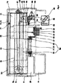
図1の斜視図には、本発明による装置を示した。ここでは装置1は、有利には計算機3として形成されたデータ処理装置2と印刷機4、特にインク式プリンタ5とを備えており、その機器制御装置26は、データライン6とインタフェイス(図示していない)とを介してデータ処理装置2と接続されていて、データ処理装置2と通信するようになっている。インク式プリンタ5は、ハウジング7でカバーされている。ハウジング7は、槽状の容器8とフード9とカバー10とを備えており、この場合カバー10は、操作兼表示エレメント11を備えている。容器8の下方に、2つのサポート12が、互いに平行に印刷機4におけるキャリッジガイドに対して特定間隔を有して、かつ直角に配置されている。サポート12は、楔形に形成されており、これによって印刷機4は、印刷方向に対して垂直の傾斜位置を占める。本発明による印刷機4の斜度は、約20度〜60度であり、有利には40度であり、サポート12の楔成形部13の傾斜によって得られる。印刷機の4有利な傾斜に基づいて、保持装置21または印刷担体22のための入口ステーション15は、出口ステーション18の上方もしくは出口ステーション18よりも高い位置に存在し、この場合両ステーション15,18は、平面23によって相互結合されている。平面23は、楔形のサポート12に基づいて、傾斜平面に相当し、この平面に沿って、保持装置21および印刷担体22が、搬送装置(図3参照)によって入口ステーション15から印刷ステーションおよび露光ステーション(図3および図4参照)を介して出口ステーション18に搬送される。入口ステーション15は、保持装置21または印刷担体22を収容するために入口トレイ16を備えており、入口トレイ16に、印刷されていない印刷対象14を有する保持装置21および印刷担体22をスタックすることができる。さらに入口トレイ16に、調節可能なサイドストッパ17が設けられており、これによって様々な寸法をした保持装置21および印刷担体22が入口トレイ16にスタック可能である。出口ステーション18は、出口トレイ19にエンドストッパ20を備えており、エンドストッパ20に、印刷された印刷対象14を有する保持装置21および印刷担体22が当接する。出口トレイ19は、入口トレイ16と同様に形成されていて、保持装置21および印刷担体22は、傾斜平面23に沿ってスタックすることができる。容器8の下方で両サポート12の間に配置されて、冷却体24が設けられており、冷却体24は、図3および図4から看取される。
The perspective view of FIG. 1 shows a device according to the invention. The
図2には、本発明による、クリーニング装置60を備えた液体供給ユニット30を概略的に断面図で示しており、ここでは液体供給ユニット30は、液体37の充填状態54を測定するため、機器32を制御するため、液体容器31に正圧を形成するため、ノズル装置45をクリーニングするための液体37を送出するために適した方法および装置を有している。液体供給ユニット30は、主に交換可能な液体容器31(液体容器31は、着脱可能な弁38を介して特にエアコンプレッサ33の機器32と管路34を介して接続されている)と、液体容器31から印刷装置40に液体37を搬送するための着脱可能な液体管路35とから成っており、印刷装置40は、閉じたハウジング41と入口開口42とリザーバ43とノズル装置45を備えた印刷ヘッド45と出口開口47とから形成されており、この場合出口開口47に、液体レベル54を測定するためのチャンバ53に開口する入口開口52と出口開口55と出口開口55に組み込まれた弁56とを備えた測定装置50、特に液体レベルセンサ51が接続されている。
FIG. 2 shows a schematic cross-sectional view of a
以下に、クリーニング装置60に関して、液体供給ユニット30の典型的な機能を説明する。
Hereinafter, typical functions of the
エアコンプレッサ33によって、液体37で印刷装置40を充填するために、正圧が、エアコンプレッサ33に向かって開いた弁38を介して、液体容器31における液体レベル36の上方で空気室に形成される。これによって液体37は、液体管路35を介して印刷装置40に向かって押し出され、これによって印刷装置40のリザーバ43に注入され、次いで出口開口47において上昇し、この場合出口開口47の上方に接続された液体絵レベルセンサ51のチャンバ53が充填される。センサ51において目標水準に到達すると、センサ51は、信号を機器制御装置26に送信し、機器制御装置26は、エアコンプレッサ33を停止し、液体レベルセンサ51の上方に位置する弁56を閉じ、液体容器31とエアコンプレッサ33との間の弁38を外気39に切り換える。これによって液体容器31における液体レベル36と印刷装置40のノズル装置45とに常時同じ雰囲気圧が作用するようになっている。ノズル装置45におけるノズル46の毛管現象によって、液体レベル36がノズル装置45に対して数ミリメートル範囲の値29で降下するか、もしくは低く位置しても、液体37はノズル装置45から滴下しない。
In order to fill the printing device 40 with the liquid 37 by the
クリーニング過程では、印刷装置40は、クリーニングステーション61に直に対向して位置する休止位置48に位置し、クリーニングステーション61は、主にクリーニング装置60と交換可能なクリーニング容器62と払拭装置63と駆動ユニット68とから成っており、この場合クリーニング容器62は、クリーニング過程において生じる液体37を収容するための開口65を備えている。休止位置48では、印刷ヘッド44は、ノズル装置45で、開口65に対して直に対向して位置する。センサ51の上方に位置する弁56は閉じられており、液体容器31の上方に位置してエアコンプレッサ33に通じる弁38は開いている。エアコンプレッサ33は、液体容器31に正圧を形成し、これによって印刷装置40のリザーバ43に含まれる液体37は、ノズル装置45から流出して、クリーニング装置60の開口65に滴下する。次いで駆動ユニット68は、クリーニング装置60を印刷ヘッド44に向かって移動させる。クリーニング装置60の昇降運動によって、払拭装置63は、ノズル装置45の高さに移動され、行方向でのキャリッジ76の運動によって、印刷ヘッド44は、払拭装置63に設けられた払拭ブレード64上を擦過して、単数または複数のノズル46に存在する残留液体を除去する。払拭された液体は、払拭ブレード64の傍に配置された小さな開口66を浸透して、クリーニング容器62の貯蔵室67に滴下する。
In the cleaning process, the printing device 40 is located at a rest position 48 that is directly opposite to the cleaning station 61, and the cleaning station 61 is driven mainly by a cleaning container 62 that can be exchanged with the cleaning device 60 and a
図3には、本発明による、傾斜した構成の印刷機4およびインクジェットプリンタ5の完全な構成を断面図で示しており、図4には、印刷機4の1実施例を縦断面図で示した。 FIG. 3 is a sectional view showing the complete construction of the printing machine 4 and the ink jet printer 5 in an inclined configuration according to the present invention. FIG. 4 is a longitudinal sectional view showing an embodiment of the printing machine 4. It was.
インク式プリンタ5は、印刷機ハウジング7の構成要素と、プリンタ枠体70と、駆動ユニット79を備えたキャリッジ76と、液体供給ユニット30(印刷装置40、液体容器31、液体レベルセンサ51およびエアコンプレッサ33から成る)と、クリーニング装置60(クリーニング容器62、払拭装置63および駆動ユニット68から成る)と、エネルギ吸収装置87および冷却エレメント24を備えた放射源86と、保持装置21および印刷担体22の搬送ローラ92,93および押圧ローラ94,95を備えた搬送装置90および引込装置91とから成っている。
The ink-type printer 5 includes components of the printing machine housing 7, a
インク式プリンタ5は、楔成形部13の構成をした支持体12を内側に配置したハウジング7を備えており、これによって印刷機4の傾斜が得られ、ならびにプリンタ枠体70を備えており、プリンタ枠体70によって、ハウジング7の側壁71,72は、桁(横材)75およびアングル桁73,74によって間隔を有して保持される。さらにインク式プリンタ5のハウジング7内に、駆動ユニット79を備えたキャリッジ76が組み付けられており、キャリッジ76は、内側で桁73,74,75に取り付けられている。キャリッジ76は、ガイド軸78を備えたキャリッジガイド77によって印刷行方向84に対して平行にガイドされ、ベルト80(ローラ81を介して変向される)を介して、駆動ユニット79によって駆動される。さらにハウジング7に取り付けられたキャリッジ76に、印刷装置40と、液体管路35を介して印刷装置40と接続された液体容器31とが配置されている。両方の構成要素40,31は、僅かな間隔98,99を有して印刷平面83上をガイドされており、この場合印刷平面83は、水平面82に対して傾斜されていて、それも交換可能な液体容器31が液体レベル36で印刷装置44のノズル装置45に対して降下した位置に存在するような程度に傾斜されている。印刷平面83もしくは平面23(平面に沿って印刷対象14がガイドされ、印刷時に出口ステーション18に搬送される)の傾斜した経過によって、交換可能な液体容器31は最上位のハウジング縁部でノズル46の下方に位置決めして、ならびに印刷行方向84で印刷装置44に対して僅かな間隔を有して配置することができる。これに対してインクタンクと印刷装置との間でレール上の間隔が少なくとも印刷対象14の幅に相当していて、印刷対象14のガイドが傾斜していない場合、液体容器31は、単に印刷装置よりも深く配置することしかできない。この場合印刷過程において、印刷対象14は、印刷行方向84でみて、液体容器31と印刷装置44との間で出口ステーション18に搬送されることになる。したがって傾斜平面によって、プリンタは特に狭幅に形成することができる。液体容器31は、弁38を介在して、液体容器31に正圧を形成するエアコンプレッサ33と接続されている。印刷装置40の出口開口47に、液体レベルセンサ51が組み込まれており、液体レベルセンサ51の出口55に弁56が接続されている。この場合印刷ヘッド44に配置されたノズル装置45に対向して、傾斜した印刷平面83の下方に、クリーニング装置60が位置しており、クリーニング装置60は、クリーニング液37を収容するためのクリーニング容器62と、ノズル装置45における残留液体を除去するための払拭ブレード64を備えた払拭装置63と、駆動ユニット68とから成っており、駆動ユニット68は、クリーニング装置60を、鉛直方向でノズル装置45に対して昇降する。印刷行方向84でみて共通のキャリッジ76上で印刷装置40の傍に、放射源86が設けられており、放射源86は、印刷対象14を、印刷過程のあとで放射により露光して、印刷パターン85を乾燥して、硬化する。放射源86の不必要なスイッチオン/オフを回避するために、印刷装置40が休止位置48に位置する場合(図4参照)、放射源86は、プリンタ4,5の運転時にスイッチオンしたままである。印刷装置40の休止位置48では、放射源86は、印刷平面83の下方に配置されたシャフト27に対向して位置する。シャフト27の終端部で、ハウジング壁の貫通孔28に、エネルギ吸収装置87が取り付けられており、エネルギ吸収装置87の斜めのリブ25で放射が複数回反射されて、熱に変換される。エネルギ吸収装置87に、外気に熱を排出するための冷却エレメント24が続いており、この場合冷却エレメント24は、両サポートの間で、水平面82に対して斜めに配置された、ハウジング7の底部に向けられた容器8から突出する。さらに印刷機4は、印刷対象14を搬送するための搬送装置90および引込装置91を備えている。印刷対象14は、保持装置21または印刷担体22に配置することができ、この場合保持装置21または印刷担体22は、個別的に、または貯蔵スタック88として、高く位置する入口ステーション15の入口トレイ16に位置し、滑落しないようにアングルストッパ96に支持される。なぜならば入口ステーション15は、傾斜した印刷平面83の高い区分に存在するからである。引込装置91によって、最下位の保持装置21または最下位の印刷担体は、入口トレイ16に位置する貯蔵スタック88から引き出され、搬送装置90(搬送ローラ92と押圧ローラ94とから成る)に供給される。搬送装置90は、保持装置21または印刷担体22を、位置正確に印刷位置89に搬送し、印刷パターン85で印刷したあとで、搬送ローラ93と押圧ローラ95とによって、排出部89に向かう出口ステーション18の出口トレイ19に搬送し、この場合排出部89は、保持装置21または印刷担体22のスタックに対して傾斜している。出口トレイ19は、傾斜した印刷平面83の比較的低い区分に位置しており、この場合保持装置21または印刷担体22は、アングルストッパ97によって出口トレイからの滑落に対して保護されている。
The ink-type printer 5 includes a housing 7 in which a
1 装置、 2 データ処理装置、 3 計算機、 4 印刷機、 5 インク式プリンタ、 6 データライン、 7 ハウジング、 8 容器、 9 フード、 10 カバー、 11 操作兼表示ユニット、 12 サポート、 13 楔(傾斜平面)、 14 印刷対象、 15 入口ステーション、 16 入口トレイ、 17 サイドストッパ、 18 出口ステーション、 19 出口トレイ、 20 エンドストッパ、 21 保持装置、 22 印刷担体、 23 傾斜平面、 24 冷却エレメント、 25 冷却リブ、 26 機器制御装置、 27 シャフト、 28 貫通孔、 29 値、 30 液体供給ユニット、 31 液体容器、 32 機器、 33 エアコンプレッサ、 34 管路、 35 液体管路、 36 液体レベル、 37 液体、 38 弁、 39 外気、 40 印刷装置、 41 ハウジング、 42 入口開口、 43 リザーバ、 44 印刷ヘッド、 45 ノズル装置、 46 ノズル、 47 出口開口、 48 休止位置、 50 測定装置、 51 液体レベルセンサ、 52 入口開口、 53 チャンバ、 54 液体レベル、 55 出口開口、 56 弁、 58 外気、 60 クリーニング装置、 61 クリーニングステーション、 62 クリーニング容器、 63 払拭装置、 64 払拭ブレード、 65 開口、 66 開口、 67 貯蔵室、 68 駆動ユニット、 70 プリンタ枠体、 71 側壁、 72 側壁、 73 アングル桁、 74 アングル桁、 75 桁、 76 キャリッジ、 77 キャリッジガイド、 78 ガイド軸、 79 駆動ユニット、 80 ベルト、 81 ローラ、 82 水平面、 83 印刷平面、 84 印刷行方向、 85 印刷パターン、 86 放射源、 87 エネルギ吸収装置、 88 放射方向、 89 印刷位置、 90 搬送装置、 91 引込装置、 92 搬送ローラ、 93 搬送ローラ、 94 押圧ローラ、 95 押圧ローラ、 96 アングルストッパ、97 アングルストッパ、 98 間隔、 99 間隔 DESCRIPTION OF SYMBOLS 1 apparatus, 2 data processing apparatus, 3 computer, 4 printing machine, 5 ink type printer, 6 data line, 7 housing, 8 container, 9 hood, 10 cover, 11 operation and display unit, 12 support, 13 wedge (inclined plane) ), 14 printing object, 15 inlet station, 16 inlet tray, 17 side stopper, 18 outlet station, 19 outlet tray, 20 end stopper, 21 holding device, 22 print carrier, 23 inclined plane, 24 cooling element, 25 cooling rib, 26 equipment controller, 27 shaft, 28 through hole, 29 value, 30 liquid supply unit, 31 liquid container, 32 equipment, 33 air compressor, 34 pipe, 35 liquid pipe, 36 liquid level, 37 liquid, 38 valve 39 Outside air, 40 printing device, 41 housing, 42 inlet opening, 43 reservoir, 44 print head, 45 nozzle device, 46 nozzle, 47 outlet opening, 48 rest position, 50 measuring device, 51 liquid level sensor, 52 inlet opening, 53 Chamber, 54 liquid level, 55 outlet opening, 56 valve, 58 outside air, 60 cleaning device, 61 cleaning station, 62 cleaning container, 63 wiping device, 64 wiping blade, 65 opening, 66 opening, 67 storage chamber, 68 drive unit, 70 Printer frame, 71 side wall, 72 side wall, 73 angle girder, 74 angle girder, 75 girder, 76 carriage, 77 carriage guide, 78 guide shaft, 79 drive unit, 80 bell 81 roller, 82 horizontal plane, 83 printing plane, 84 printing line direction, 85 printing pattern, 86 radiation source, 87 energy absorbing device, 88 radiation direction, 89 printing position, 90 transport device, 91 pull-in device, 92 transport roller, 93 Conveying roller, 94 Pressing roller, 95 Pressing roller, 96 Angle stopper, 97 Angle stopper, 98 interval, 99 interval
Claims (9)
印刷機(4)を制御するためのデータ処理装置(2)が設けられており、印刷機(4)が、保持装置(21)または印刷担体(22)を搬送するための搬送装置(90)と、プラスチック部分を印刷するための、ノズル装置(45)を備えた印刷装置(40)と、液体ジェットによって形成される印刷パターン(85)を乾燥して硬化するための放射源(86)と、放射源(86)のエネルギを吸収するためのエネルギ吸収装置(87)と、印刷装置(40)に液体を供給するための交換可能な液体容器(31)と、ノズル装置(45)をクリーニングするための交換可能なクリーニング装置(60)と、保持装置(21)のための入口ステーション(15)および出口ステーション(18)とを備えている形式のものにおいて、
印刷装置(40)、放射源(86)および液体容器(31)が、往復運動可能なキャリッジ(76)上に配置されており、印刷装置(40)が休止位置に位置する場合に、印刷装置(40)にクリーニング装置(60)が対向し、放射源(86)にエネルギ吸収装置(87)が対向することを特徴とする、印刷対象、特にプラスチック部分を印刷する装置。A device for printing a print object, in particular a plastic part,
A data processing device (2) for controlling the printing press (4) is provided, and the transport device (90) for the printing press (4) to transport the holding device (21) or the print carrier (22). A printing device (40) with a nozzle device (45) for printing the plastic part, and a radiation source (86) for drying and curing the printed pattern (85) formed by the liquid jet. Cleaning the energy absorbing device (87) for absorbing the energy of the radiation source (86), the replaceable liquid container (31) for supplying liquid to the printing device (40), and the nozzle device (45). In the form of a replaceable cleaning device (60) for carrying out and an inlet station (15) and an outlet station (18) for the holding device (21),
When the printing device (40), the radiation source (86) and the liquid container (31) are arranged on a reciprocating carriage (76) and the printing device (40) is in the rest position, the printing device A device for printing a print object, in particular a plastic part, characterized in that the cleaning device (60) faces the (40) and the energy absorption device (87) faces the radiation source (86) .
Applications Claiming Priority (3)
| Application Number | Priority Date | Filing Date | Title |
|---|---|---|---|
| DE102006003056.7 | 2006-01-20 | ||
| DE102006003056.7A DE102006003056B4 (en) | 2006-01-20 | 2006-01-20 | Ink printer for printing on objects |
| PCT/EP2007/000109 WO2007087957A1 (en) | 2006-01-20 | 2007-01-09 | Method and apparatus for printing objects, in particular plastic parts |
Publications (2)
| Publication Number | Publication Date |
|---|---|
| JP2009523626A JP2009523626A (en) | 2009-06-25 |
| JP5145246B2 true JP5145246B2 (en) | 2013-02-13 |
Family
ID=38001680
Family Applications (1)
| Application Number | Title | Priority Date | Filing Date |
|---|---|---|---|
| JP2008550662A Expired - Fee Related JP5145246B2 (en) | 2006-01-20 | 2007-01-09 | Equipment for printing objects, especially plastic parts |
Country Status (8)
| Country | Link |
|---|---|
| US (1) | US8303100B2 (en) |
| EP (1) | EP1973744B1 (en) |
| JP (1) | JP5145246B2 (en) |
| CN (1) | CN101374669B (en) |
| AT (1) | ATE465884T1 (en) |
| DE (2) | DE102006003056B4 (en) |
| ES (1) | ES2343379T3 (en) |
| WO (1) | WO2007087957A1 (en) |
Families Citing this family (30)
| Publication number | Priority date | Publication date | Assignee | Title |
|---|---|---|---|---|
| US9422095B2 (en) | 2007-07-31 | 2016-08-23 | Phoenix Contact Gmbh & Co. Kg | Marking object |
| DE102007036374A1 (en) | 2007-07-31 | 2009-02-05 | Phoenix Contact Gmbh & Co. Kg | Marking object and marking device |
| DE102008034839B4 (en) * | 2008-03-14 | 2012-09-27 | Peter Jakob | Method for the digital printing of objects by means of an inkjet printer |
| DE102008060451B4 (en) * | 2008-12-05 | 2015-04-16 | Phoenix Contact Gmbh & Co. Kg | positioning |
| CN102069671A (en) * | 2009-11-20 | 2011-05-25 | 汉达精密电子(昆山)有限公司 | Method for making multicolor graph with bright shining effect |
| CN102101413A (en) * | 2009-12-18 | 2011-06-22 | 深圳富泰宏精密工业有限公司 | Shell manufacturing method and shell manufactured by method |
| DE102010037564A1 (en) | 2010-08-12 | 2012-02-16 | Phoenix Contact Gmbh & Co. Kg | Printing object and printer for printing on a printing object |
| DE102010036113B4 (en) | 2010-09-01 | 2013-03-21 | Slee Medical Gmbh | Laboratory identification printing device for tissue cassettes, slides and other laboratory or sample containers |
| WO2012036874A2 (en) | 2010-09-13 | 2012-03-22 | Primera Technology, Inc. | Cartridge for histological specimen slides |
| US9327516B2 (en) | 2010-09-13 | 2016-05-03 | Primera Technology, Inc. | Histological specimen cassette |
| CN102673126A (en) * | 2011-03-18 | 2012-09-19 | 杭州骏骋塑业有限公司 | Novel process for manufacturing label plate layouts of electric energy meter |
| DE202011005278U1 (en) * | 2011-04-15 | 2012-09-20 | Euroimmun Medizinische Labordiagnostika Ag | slides |
| US9007411B2 (en) | 2012-09-19 | 2015-04-14 | Primera Technology, Inc. | Reverse transfer color printers for histological specimen slides and cassettes |
| DE102013104780A1 (en) | 2013-05-08 | 2014-11-13 | Weidmüller Interface GmbH & Co. KG | Magazine device and method for stacking printed marker mats |
| CN104417066A (en) * | 2013-09-09 | 2015-03-18 | 北大方正集团有限公司 | Flash spray control method and equipment |
| JP6291761B2 (en) * | 2013-09-19 | 2018-03-14 | セイコーエプソン株式会社 | Printing device |
| CN104085191B (en) * | 2014-07-19 | 2016-03-23 | 刘小欣 | The ink jet printing equipment of a kind of method that ink jet prints on plastics and application the method |
| DE102015114740A1 (en) | 2015-09-03 | 2017-03-09 | Designbar Solutions GmbH | Device for product presentation and positioning for use with a printing device |
| DE102015119681A1 (en) * | 2015-11-13 | 2017-05-18 | Phoenix Contact Gmbh & Co. Kg | Method for inputting print data for printing on a printing object with a printer and printing system with at least two printers |
| DE102016101111B3 (en) | 2016-01-22 | 2017-04-13 | Phoenix Contact Gmbh & Co. Kg | Printer for printing on printing objects |
| JP6784077B2 (en) * | 2016-06-29 | 2020-11-11 | 富士ゼロックス株式会社 | Droplet ejection device |
| DE102017205357B4 (en) | 2017-03-29 | 2021-09-16 | PrintoLUX GmbH | Process for the machine or manual production of a flat information carrier by lamination |
| IT201700097823A1 (en) | 2017-08-31 | 2019-03-03 | Skf Ab | LOW FRICTION SEALING COMPLEX, COUPLING SYSTEM WITH A BEARING RING AND HUB WHEEL UNIT EQUIPPED WITH THIS SEALING COMPLEX |
| IT201700119131A1 (en) * | 2017-10-20 | 2019-04-20 | Nuova Ompi Srl | System for the realization of marked containers and relative method |
| DE102017129768B3 (en) | 2017-12-13 | 2019-03-28 | Océ Holding B.V. | Method and apparatus for testing an ink jet printhead |
| CN110254049B (en) * | 2018-01-18 | 2020-08-25 | 深圳市东方时通科技发展有限公司 | Slide printer |
| WO2020174017A1 (en) * | 2019-02-27 | 2020-09-03 | Weidmüller Interface GmbH & Co. KG | Printer for printing marker cards with marks for marking electrical devices |
| CN110228301B (en) * | 2019-08-07 | 2019-12-06 | 上海韬涵医疗科技有限公司 | Slide printing device |
| DE102020215072A1 (en) * | 2020-11-30 | 2022-06-02 | Ekra Automatisierungssysteme Gmbh | storage system and printing system |
| US11884088B2 (en) * | 2021-05-26 | 2024-01-30 | Xerox Corporation | System and method for printing documents with texture |
Family Cites Families (38)
| Publication number | Priority date | Publication date | Assignee | Title |
|---|---|---|---|---|
| DE8200185U1 (en) * | 1982-01-07 | 1982-05-13 | J. Hengstler Kg, 7209 Aldingen | PRINTER WITH RECEIPT FEEDER |
| US4771295B1 (en) * | 1986-07-01 | 1995-08-01 | Hewlett Packard Co | Thermal ink jet pen body construction having improved ink storage and feed capability |
| GB8915140D0 (en) * | 1989-06-30 | 1989-08-23 | Lamb Raymond A | Device for marking supports for laboratory samples |
| AT392286B (en) * | 1989-08-24 | 1991-02-25 | Kuehtreiber Franz | DEFLECTOR DEVICE |
| US5256224A (en) * | 1991-12-31 | 1993-10-26 | E. I. Du Pont De Nemours And Company | Process for making molded, tufted polyolefin carpet |
| JPH06270475A (en) * | 1993-03-24 | 1994-09-27 | Sanyo Electric Co Ltd | Drug bag printer |
| DE4342643C2 (en) * | 1993-09-13 | 1999-04-29 | Fraunhofer Ges Forschung | Low-temperature fixation with barrier discharge in inkjet printers |
| US6007177A (en) * | 1994-11-30 | 1999-12-28 | Canon Kabushiki Kaisha | Cap for ink jet recording head with rinsing liquid supplied thereto |
| DE69801124T2 (en) * | 1997-02-05 | 2001-10-31 | Fuji Photo Film Co., Ltd. | Direct thermal recording printer, direct thermal recording printing method and transport device for recording material |
| DE19726236C2 (en) * | 1997-06-20 | 2002-11-07 | Weidmueller Interface | laser |
| DE19823195C2 (en) * | 1998-05-23 | 2003-03-20 | Doellken & Co Gmbh W | Method and device for printing on plastic workpiece surfaces |
| JP2000113511A (en) * | 1998-09-30 | 2000-04-21 | Fuji Photo Film Co Ltd | Optical information recording medium |
| GB9825359D0 (en) | 1998-11-20 | 1999-01-13 | Xaar Technology Ltd | Methods of inkjet printing |
| DE19916219C2 (en) * | 1999-04-10 | 2001-03-22 | Tally Computerdrucker Gmbh | Ink printer with a carriage that can be moved back and forth at least with a nozzle head |
| DE19923291B4 (en) * | 1999-05-21 | 2004-10-07 | Tally Computerdrucker Gmbh | Ink printer with an ink-liquid compound for one or more ink colors |
| US6523921B2 (en) * | 2000-08-30 | 2003-02-25 | L&P Property Management | Method and apparatus for printing on rigid panels and other contoured or textured surfaces |
| DE20022158U1 (en) * | 2000-11-10 | 2001-03-29 | Advanced Photonics Technologies AG, 83052 Bruckmühl | Small drying device |
| JP2002187292A (en) * | 2000-12-21 | 2002-07-02 | Seiko Epson Corp | INK JET RECORDING APPARATUS AND METHOD OF CONTROLLING INK SUPPLY TO SUBTANK IN THE APPARATUS |
| DE20104158U1 (en) * | 2001-03-09 | 2001-08-02 | Leica Microsystems Nussloch GmbH, 69226 Nußloch | Cassette stack with cassettes for histological preparations |
| JP2002264358A (en) * | 2001-03-12 | 2002-09-18 | Ricoh Co Ltd | Inkjet image forming equipment |
| DE10115065A1 (en) * | 2001-03-27 | 2002-10-02 | Leica Microsystems | Method and device for printing on cassettes or slides for histological preparations |
| JP2002292907A (en) * | 2001-03-30 | 2002-10-09 | Brother Ind Ltd | Color inkjet recording device |
| CN2472928Y (en) * | 2001-04-14 | 2002-01-23 | 谢远生 | Digital printer |
| DE10143803A1 (en) * | 2001-09-06 | 2003-03-27 | Leica Microsystems | Label imprinting apparatus for e.g. cassettes, has pivot device for aligning printing head with differently inclined printing planes, or vice versa |
| JP4848109B2 (en) * | 2001-09-18 | 2011-12-28 | 芝浦メカトロニクス株式会社 | Coating device |
| JP2004042525A (en) * | 2002-07-15 | 2004-02-12 | Konica Minolta Holdings Inc | Inkjet printer and image forming method |
| JP4182720B2 (en) * | 2002-10-16 | 2008-11-19 | セイコーエプソン株式会社 | Supply of ink from the main tank to the sub tank of the printing device |
| JP4345293B2 (en) * | 2002-12-04 | 2009-10-14 | セイコーエプソン株式会社 | Functional liquid filling method for liquid droplet ejection device and liquid droplet ejection device |
| JP2004330773A (en) * | 2003-04-18 | 2004-11-25 | Konica Minolta Medical & Graphic Inc | Ink-jet printer |
| JP4461728B2 (en) * | 2003-07-29 | 2010-05-12 | ブラザー工業株式会社 | Inkjet recording apparatus and ink supply apparatus |
| JP2005144679A (en) * | 2003-11-11 | 2005-06-09 | Roland Dg Corp | Inkjet printer |
| TWM249817U (en) * | 2003-12-05 | 2004-11-11 | Benq Corp | Ink removing apparatus |
| JP4517654B2 (en) * | 2004-01-30 | 2010-08-04 | コニカミノルタエムジー株式会社 | Inkjet recording device |
| DE102004012078A1 (en) * | 2004-03-12 | 2005-09-29 | Werner Kammann Maschinenfabrik Gmbh & Co. Kg | Device for feeding and removing objects to and from a machine for decorating the same |
| JP2005349636A (en) * | 2004-06-09 | 2005-12-22 | Olympus Corp | Liquid droplet discharging head and image recorder carrying this head |
| JP2006008791A (en) * | 2004-06-24 | 2006-01-12 | Konica Minolta Medical & Graphic Inc | Active ray-curable composition, active ray-curable ink, and image forming method and inkjet recording apparatus using the same |
| JP2006062139A (en) * | 2004-08-25 | 2006-03-09 | Toshiba Tec Corp | Ink filtration device, ink filtration method, ink and inkjet recording device |
| US7874656B2 (en) * | 2004-12-10 | 2011-01-25 | Canon Finetech Inc. | Ink-feeding device and pressure-generating method |
-
2006
- 2006-01-20 DE DE102006003056.7A patent/DE102006003056B4/en active Active
-
2007
- 2007-01-09 ES ES07711322T patent/ES2343379T3/en active Active
- 2007-01-09 AT AT07711322T patent/ATE465884T1/en active
- 2007-01-09 EP EP07711322A patent/EP1973744B1/en not_active Not-in-force
- 2007-01-09 CN CN2007800032852A patent/CN101374669B/en not_active Expired - Fee Related
- 2007-01-09 JP JP2008550662A patent/JP5145246B2/en not_active Expired - Fee Related
- 2007-01-09 DE DE502007003587T patent/DE502007003587D1/en active Active
- 2007-01-09 WO PCT/EP2007/000109 patent/WO2007087957A1/en not_active Ceased
- 2007-01-09 US US12/161,673 patent/US8303100B2/en not_active Expired - Fee Related
Also Published As
| Publication number | Publication date |
|---|---|
| JP2009523626A (en) | 2009-06-25 |
| DE502007003587D1 (en) | 2010-06-10 |
| US8303100B2 (en) | 2012-11-06 |
| WO2007087957A1 (en) | 2007-08-09 |
| CN101374669B (en) | 2010-09-01 |
| DE102006003056B4 (en) | 2014-05-08 |
| US20100220162A1 (en) | 2010-09-02 |
| EP1973744B1 (en) | 2010-04-28 |
| DE102006003056A1 (en) | 2007-07-26 |
| CN101374669A (en) | 2009-02-25 |
| ATE465884T1 (en) | 2010-05-15 |
| ES2343379T3 (en) | 2010-07-29 |
| EP1973744A1 (en) | 2008-10-01 |
Similar Documents
| Publication | Publication Date | Title |
|---|---|---|
| JP5145246B2 (en) | Equipment for printing objects, especially plastic parts | |
| EP2546061B1 (en) | Recording apparatus | |
| US20090255460A1 (en) | Applying a protective coating to marked media in a print engine | |
| CN102815090A (en) | Printing apparatus and control method thereof | |
| JP2009073012A (en) | Liquid ejector | |
| JP5573450B2 (en) | Recording device | |
| CN102501628B (en) | Tape deck | |
| US8100522B2 (en) | Recording apparatus and recording method of recording apparatus | |
| PT1749670E (en) | Fluid ejection machine for coating deposition | |
| JP2013512120A (en) | Sheet processing device | |
| JP5251351B2 (en) | Liquid ejector | |
| EP1283781B1 (en) | Ink jet card printer | |
| WO2022210915A1 (en) | Liquid discharge head, discharge head structure, and recording device | |
| CN102180017B (en) | Fluid ejecting apparatus | |
| JP5157341B2 (en) | Liquid ejector | |
| US8328327B2 (en) | Liquid ejection apparatus | |
| WO2018074258A1 (en) | Liquid droplet discharge device | |
| JP2009040002A (en) | Inkjet printing system | |
| US20150009266A1 (en) | Ink cartridge and ink jet printer | |
| JP2005119802A (en) | Ink jet recording device | |
| JP2005271582A (en) | Image recording device | |
| US20050190224A1 (en) | Image recording apparatus | |
| JP2009190188A (en) | Inkjet head and inkjet recording device | |
| JP5790107B2 (en) | Coating material drying device and recording device | |
| JP2009073011A (en) | Liquid ejector |
Legal Events
| Date | Code | Title | Description |
|---|---|---|---|
| A621 | Written request for application examination |
Free format text: JAPANESE INTERMEDIATE CODE: A621 Effective date: 20091029 |
|
| RD04 | Notification of resignation of power of attorney |
Free format text: JAPANESE INTERMEDIATE CODE: A7424 Effective date: 20101228 Free format text: JAPANESE INTERMEDIATE CODE: A7424 Effective date: 20101227 |
|
| A131 | Notification of reasons for refusal |
Free format text: JAPANESE INTERMEDIATE CODE: A131 Effective date: 20110916 |
|
| A601 | Written request for extension of time |
Free format text: JAPANESE INTERMEDIATE CODE: A601 Effective date: 20111216 |
|
| A602 | Written permission of extension of time |
Free format text: JAPANESE INTERMEDIATE CODE: A602 Effective date: 20111226 |
|
| A601 | Written request for extension of time |
Free format text: JAPANESE INTERMEDIATE CODE: A601 Effective date: 20120116 |
|
| A602 | Written permission of extension of time |
Free format text: JAPANESE INTERMEDIATE CODE: A602 Effective date: 20120123 |
|
| A521 | Request for written amendment filed |
Free format text: JAPANESE INTERMEDIATE CODE: A523 Effective date: 20120208 |
|
| A131 | Notification of reasons for refusal |
Free format text: JAPANESE INTERMEDIATE CODE: A131 Effective date: 20120516 |
|
| A601 | Written request for extension of time |
Free format text: JAPANESE INTERMEDIATE CODE: A601 Effective date: 20120718 |
|
| A602 | Written permission of extension of time |
Free format text: JAPANESE INTERMEDIATE CODE: A602 Effective date: 20120725 |
|
| A601 | Written request for extension of time |
Free format text: JAPANESE INTERMEDIATE CODE: A601 Effective date: 20120918 |
|
| A602 | Written permission of extension of time |
Free format text: JAPANESE INTERMEDIATE CODE: A602 Effective date: 20120925 |
|
| A521 | Request for written amendment filed |
Free format text: JAPANESE INTERMEDIATE CODE: A523 Effective date: 20121012 |
|
| TRDD | Decision of grant or rejection written | ||
| A01 | Written decision to grant a patent or to grant a registration (utility model) |
Free format text: JAPANESE INTERMEDIATE CODE: A01 Effective date: 20121109 |
|
| A01 | Written decision to grant a patent or to grant a registration (utility model) |
Free format text: JAPANESE INTERMEDIATE CODE: A01 |
|
| A61 | First payment of annual fees (during grant procedure) |
Free format text: JAPANESE INTERMEDIATE CODE: A61 Effective date: 20121126 |
|
| FPAY | Renewal fee payment (event date is renewal date of database) |
Free format text: PAYMENT UNTIL: 20151130 Year of fee payment: 3 |
|
| R150 | Certificate of patent or registration of utility model |
Ref document number: 5145246 Country of ref document: JP Free format text: JAPANESE INTERMEDIATE CODE: R150 Free format text: JAPANESE INTERMEDIATE CODE: R150 |
|
| R250 | Receipt of annual fees |
Free format text: JAPANESE INTERMEDIATE CODE: R250 |
|
| R250 | Receipt of annual fees |
Free format text: JAPANESE INTERMEDIATE CODE: R250 |
|
| R250 | Receipt of annual fees |
Free format text: JAPANESE INTERMEDIATE CODE: R250 |
|
| R250 | Receipt of annual fees |
Free format text: JAPANESE INTERMEDIATE CODE: R250 |
|
| R250 | Receipt of annual fees |
Free format text: JAPANESE INTERMEDIATE CODE: R250 |
|
| R250 | Receipt of annual fees |
Free format text: JAPANESE INTERMEDIATE CODE: R250 |
|
| R250 | Receipt of annual fees |
Free format text: JAPANESE INTERMEDIATE CODE: R250 |
|
| LAPS | Cancellation because of no payment of annual fees |