JP5146708B2 - Compressed data transmission / reception device, data compression device, compressed data reception device, and data compression method - Google Patents
Compressed data transmission / reception device, data compression device, compressed data reception device, and data compression method Download PDFInfo
- Publication number
- JP5146708B2 JP5146708B2 JP2011520849A JP2011520849A JP5146708B2 JP 5146708 B2 JP5146708 B2 JP 5146708B2 JP 2011520849 A JP2011520849 A JP 2011520849A JP 2011520849 A JP2011520849 A JP 2011520849A JP 5146708 B2 JP5146708 B2 JP 5146708B2
- Authority
- JP
- Japan
- Prior art keywords
- data
- compression
- compressed
- compressed data
- address information
- Prior art date
- Legal status (The legal status is an assumption and is not a legal conclusion. Google has not performed a legal analysis and makes no representation as to the accuracy of the status listed.)
- Expired - Fee Related
Links
- 238000013144 data compression Methods 0.000 title claims description 50
- 238000000034 method Methods 0.000 title claims description 37
- 230000005540 biological transmission Effects 0.000 title claims description 28
- 238000007906 compression Methods 0.000 claims description 157
- 230000006835 compression Effects 0.000 claims description 146
- 230000006837 decompression Effects 0.000 claims description 88
- 238000012545 processing Methods 0.000 claims description 31
- 238000007781 pre-processing Methods 0.000 claims description 18
- 238000012805 post-processing Methods 0.000 claims description 15
- 230000002441 reversible effect Effects 0.000 claims description 7
- 230000008569 process Effects 0.000 claims description 4
- 238000003860 storage Methods 0.000 description 21
- 238000010586 diagram Methods 0.000 description 17
- 238000006243 chemical reaction Methods 0.000 description 6
- 238000012360 testing method Methods 0.000 description 5
- 230000008859 change Effects 0.000 description 3
- 238000004519 manufacturing process Methods 0.000 description 3
- 230000002123 temporal effect Effects 0.000 description 3
- 238000004587 chromatography analysis Methods 0.000 description 1
- 238000004891 communication Methods 0.000 description 1
- 238000012937 correction Methods 0.000 description 1
- 230000004069 differentiation Effects 0.000 description 1
- 230000000694 effects Effects 0.000 description 1
- 238000005304 joining Methods 0.000 description 1
- 238000012986 modification Methods 0.000 description 1
- 230000004048 modification Effects 0.000 description 1
- 230000003252 repetitive effect Effects 0.000 description 1
- 230000004044 response Effects 0.000 description 1
Images


Classifications
-
- H—ELECTRICITY
- H03—ELECTRONIC CIRCUITRY
- H03M—CODING; DECODING; CODE CONVERSION IN GENERAL
- H03M7/00—Conversion of a code where information is represented by a given sequence or number of digits to a code where the same, similar or subset of information is represented by a different sequence or number of digits
- H03M7/30—Compression; Expansion; Suppression of unnecessary data, e.g. redundancy reduction
- H03M7/3084—Compression; Expansion; Suppression of unnecessary data, e.g. redundancy reduction using adaptive string matching, e.g. the Lempel-Ziv method
- H03M7/3086—Compression; Expansion; Suppression of unnecessary data, e.g. redundancy reduction using adaptive string matching, e.g. the Lempel-Ziv method employing a sliding window, e.g. LZ77
-
- H—ELECTRICITY
- H03—ELECTRONIC CIRCUITRY
- H03M—CODING; DECODING; CODE CONVERSION IN GENERAL
- H03M7/00—Conversion of a code where information is represented by a given sequence or number of digits to a code where the same, similar or subset of information is represented by a different sequence or number of digits
- H03M7/30—Compression; Expansion; Suppression of unnecessary data, e.g. redundancy reduction
- H03M7/60—General implementation details not specific to a particular type of compression
- H03M7/6017—Methods or arrangements to increase the throughput
- H03M7/6023—Parallelization
Landscapes
- Engineering & Computer Science (AREA)
- Theoretical Computer Science (AREA)
- Compression, Expansion, Code Conversion, And Decoders (AREA)
Description
本発明は、圧縮データ送受信装置、データ圧縮装置、圧縮データ受信装置及びデータ圧縮方法に関し、特に、圧縮度を適宜変更する圧縮データ送受信装置、データ圧縮装置、圧縮データ送受信システム及びデータ圧縮方法に関する。 The present invention relates to a compressed data transmission / reception device, a data compression device, a compressed data reception device, and a data compression method, and more particularly, to a compressed data transmission / reception device, a data compression device, a compressed data transmission / reception system, and a data compression method.
FPGA(Field Programmable Gate Array)に代表される再構成可能デバイスは、構成情報の読み込みに、非常に長い時間を必要とする。その結果、例えば、再構成可能デバイスの試験を行うために、構成情報を何度も更新するような場合には、試験時間において構成情報の読み込み時間が支配的となってしまう。それゆえ、構成情報の読み込み時間を短縮するために、構成情報を圧縮データとして再構成可能デバイスに与え、再構成可能デバイス内部において、圧縮データを伸長して構成情報を得るようにすることが望まれている。
一方、データを圧縮して送受信する技術は、従来からデータ通信の分野においてよく知られている(例えば、特許文献1参照)。
また、データの圧縮レベルを、受信側において伸長可能なレベルに変換する技術も知られている(例えば、特許文献2参照)。
また、従来から、データの種類に応じて圧縮を行う技術も知られている(例えば、特許文献3参照)。
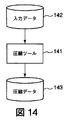
図14は、送信側におけるデータの圧縮処理を模式的に示す図である。圧縮ツール141は、送信しようとするデータ(入力データ)142を圧縮し、圧縮データ143として出力する。
図15は、関連するバッファ型受信装置150を模式的に示す図である。バッファ型受信装置150は、伸長回路151と、受信回路152とを備え、さらにこれらの間にバッファ回路153を備えている。送信側から送信された圧縮データ143は、伸長回路151に供給され、伸長される。伸長されたデータはバッファ回路153に一旦蓄積され、その後、受信回路152に読み出される。
図16は、伸長回路151の伸長速度(出力データレート)の時間変化を示すグラフである。伸長回路151の伸長速度は、必ずしも一定ではなく、時間の経過とともに変化する。バッファ回路153は、伸長回路151の伸長速度が受信回路152の受信速度(速度限界又は最大受信速度)を上回ったとき、受信回路152が受信し切れなかったデータを一時的に保存し、データのオーバフローを防止する。
図17は、関連する圧縮データ変換装置を模式的に示す図である。変換回路171は、低性能伸長回路172において伸長処理が可能となるように、高圧縮データ173を一旦伸長し、伸長したデータを低圧縮データ174に変換する。これにより、図18に示すように、低性能伸長回路172における平均伸長速度を向上させることができる。
On the other hand, a technique for compressing and transmitting / receiving data has been well known in the field of data communication (see, for example, Patent Document 1).
In addition, a technique for converting a data compression level to a level that can be expanded on the receiving side is also known (see, for example, Patent Document 2).
Conventionally, a technique for performing compression according to the type of data is also known (see, for example, Patent Document 3).
FIG. 14 is a diagram schematically illustrating data compression processing on the transmission side. The
FIG. 15 is a diagram schematically showing a related buffer
FIG. 16 is a graph showing temporal changes in the decompression speed (output data rate) of the
FIG. 17 is a diagram schematically illustrating a related compressed data conversion apparatus. The
再構成可能デバイスに構成情報を圧縮データとして与える場合、再構成可能デバイスから送信側に対して圧縮データの送信停止を要求する等のフロー制御を行うことができない、ということを前提としなければならない。このため、圧縮データ受信装置において、圧縮データを伸長する伸長回路の伸長速度と伸長されたデータを受信する受信回路の受信速度との間に差が存在する場合には、その差を吸収するためのバッファ回路が必須となる。
伸長回路と受信回路との間に設けられるバッファ回路は、データのオーバフローが生じない大きさの記憶容量を持つ必要がある。しかしながら、バッファ回路に必要とされる記憶容量を適切に見積もることは困難である。そのため、関連する圧縮データ受信装置では、必要以上に大きな記憶容量を持つバッファ回路が使用され、圧縮データ受信装置の製造コストの上昇を招いている。
特許文献2に記載された技術は、受信側において伸長可能となるように圧縮レベルを変更するものである。しかし、この技術は、圧縮データ全体の圧縮度を変更するものなので、受信側の装置構成を簡略化しようとすると、圧縮データ全体の圧縮度を低下させることになる。したがって、特許文献2に記載された技術は、より高い圧縮率の圧縮データを再構成可能デバイスに与えるという使用目的には適していない。
また、特許文献3に記載された技術は、画像情報変換装置(圧縮処理)におけるアンダーフロー及びオーバフローを抑制するものである。即ち、この技術は、送信側において圧縮されたデータのビットレートを一定にしようとするものである。特許文献3においても、特許文献2と同様に、受信側の装置構成を簡略化しようとすると、圧縮データ全体の圧縮度低下につながる。
本発明は上述した問題の1つ又はいくつかの問題を解決することのできるデータ圧縮方法、データ圧縮装置、圧縮データ受信装置及び圧縮データ送受信装置を提供する。When providing configuration information as compressed data to a reconfigurable device, it must be assumed that flow control such as requesting the transmission side to stop transmitting compressed data from the reconfigurable device cannot be performed. . Therefore, in the compressed data receiving apparatus, if there is a difference between the decompression speed of the decompression circuit for decompressing the compressed data and the reception speed of the reception circuit for receiving the decompressed data, the difference is absorbed. The buffer circuit is essential.
The buffer circuit provided between the decompression circuit and the reception circuit needs to have a storage capacity large enough to prevent data overflow. However, it is difficult to appropriately estimate the storage capacity required for the buffer circuit. For this reason, in the related compressed data receiving apparatus, a buffer circuit having a storage capacity larger than necessary is used, which increases the manufacturing cost of the compressed data receiving apparatus.
The technique described in Patent Document 2 changes the compression level so that it can be decompressed on the receiving side. However, since this technique changes the degree of compression of the entire compressed data, if the apparatus configuration on the receiving side is to be simplified, the degree of compression of the entire compressed data is reduced. Therefore, the technique described in Patent Document 2 is not suitable for the intended purpose of providing compressed data with a higher compression rate to a reconfigurable device.
The technique described in Patent Document 3 suppresses underflow and overflow in the image information conversion apparatus (compression process). That is, this technique is intended to make the bit rate of the data compressed on the transmission side constant. Also in Patent Document 3, as in Patent Document 2, if the device configuration on the receiving side is to be simplified, the compression degree of the entire compressed data is reduced.
The present invention provides a data compression method, data compression apparatus, compressed data reception apparatus, and compressed data transmission / reception apparatus that can solve one or several of the problems described above.
本発明の1視点によれば、圧縮データを送信する送信装置と圧縮データを復元して受信する受信装置とを含む圧縮データ送受信装置は、前記送信装置は圧縮データを少なくとも1のデータ単位に対応して用意された互いに符合長の異なる複数の符合語の1つを前記受信装置の予め定められた受信速度を超えないように適応的に割当てて生成する圧縮手段を含む、
本発明の第2の視点によれば、入力データを圧縮して圧縮データを生成するデータ圧縮方法は、圧縮データを少なくとも1のデータ単位に対応して用意された互いに符合長の異なる複数の符合語の1つを適応的に割当てて生成し、前記圧縮データの圧縮度を符合語単位で調整することを特徴とする。
本発明の第3の視点によれば、圧縮データを少なくとも1のデータ単位に対応して用意された互いに符合長の異なる複数の符合語の1つを受信装置の予め定められた受信速度を超えないように適応的に割当てて生成する圧縮手段を含むデータ圧縮装置が得られる。
本発明の他の視点によれば、圧縮データ受信装置が得られる。圧縮データ受信装置は、圧縮データを伸張する伸張回路と、前記伸張回路によって伸張された伸張データを受信する受信回路とを備える。前記伸張回路は、少なくとも1のデータ単位に対応して用意された互いに符合長の異なる複数の符合語の1つを適応的に割当てられて構成された圧縮データを伸張する伸張手段を含み、前記伸張回路と前記受信回路とはバッファ回路を介さずに又小容量バッファ回路を介しては接続されている。According to one aspect of the present invention, a compressed data transmission / reception device including a transmission device that transmits compressed data and a reception device that restores and receives compressed data, the transmission device corresponds to at least one data unit of compressed data. Compression means for adaptively assigning and generating one of a plurality of code words having different code lengths prepared in such a manner as not to exceed a predetermined reception speed of the receiving device,
According to a second aspect of the present invention, a data compression method for compressing input data to generate compressed data includes a plurality of codes having different code lengths prepared for at least one data unit. One of the words is adaptively assigned and generated, and the compression degree of the compressed data is adjusted in codeword units.
According to the third aspect of the present invention, one of a plurality of code words having different code lengths prepared corresponding to at least one data unit of compressed data exceeds a predetermined reception speed of the receiving apparatus. Thus, a data compression apparatus including compression means for adaptively assigning and generating such that there is no need is obtained.
According to another aspect of the present invention, a compressed data receiving apparatus is obtained. The compressed data receiving apparatus includes a decompression circuit that decompresses compressed data and a reception circuit that receives decompressed data decompressed by the decompression circuit. The decompression circuit includes decompression means for decompressing compressed data configured by adaptively assigning one of a plurality of code words having different code lengths prepared corresponding to at least one data unit, The decompression circuit and the receiving circuit are connected not via the buffer circuit or via the small-capacity buffer circuit.
図1は、本発明の第1の実施の形態に係る圧縮データ送受信装置に用いられるデータ圧縮装置の概略構成を示すブロック図である。
図2は、図1のデータ圧縮装置に含まれる調整圧縮ツールの概略構成を示すブロック図である。
図3は、本発明の第1の実施の形態に係る圧縮データ送受信装置に用いられる圧縮データ受信装置の概略構成を示すブロック図である。
図4は、図3の圧縮データ受信装置に含まれる伸長回路の伸長速度の時間変化を示すグラフである。
図5は、本発明の第2の実施の形態に係る圧縮データ送受信装置のデータ圧縮装置の概略構成を示すブロック図である。
図6は、図5のデータ圧縮装置の動作を説明するためのフローチャートである。
図7は、本発明の第2の実施の形態に係る圧縮データ送受信装置の圧縮データ受信装置の概略構成を示すブロック図である。
図8は、図7の圧縮データ受信装置の動作を説明するためのフローチャートである。
図9は、図5のデータ圧縮装置による圧縮工程及び図7の圧縮データ受信装置による伸長工程のアドレス及びデータの変化を説明するための図である。
図10A及び図10Bは、それぞれ差分アドレス群の圧縮に用いられる圧縮規則の一例を示す図、分割データ群の圧縮に用いられる圧縮規則の一例を示す図である。
図11は、本発明の第3の実施の形態に係る圧縮データ送受信装置に用いられるデータ圧縮装置の概略構成を示すブロック図である。
図12は、本発明の第3の実施の形態に係る圧縮データ送受信装置に用いられる圧縮データ受信装置の概略構成を示すブロック図である。
図13は、図12の圧縮データ受信装置に含まれる伸長回路の伸長速度の時間変化を示すグラフである。
図14は、関連するデータ圧縮装置の概略構成を示すブロック図である。
図15は、関連する圧縮データ受信装置の概略構成を示すブロック図である。
図16は、図15の圧縮データ受信装置における伸長速度の時間変化を示すグラフである。
図17は、関連する圧縮データ変換装置の概略構成を示すブロック図である。
図18は、図17の圧縮データ変換装置に用いられる低性能伸長回路の伸長速度の時間変化を示すグラフである。FIG. 1 is a block diagram showing a schematic configuration of a data compression apparatus used in the compressed data transmission / reception apparatus according to the first embodiment of the present invention.
FIG. 2 is a block diagram showing a schematic configuration of the adjustment compression tool included in the data compression apparatus of FIG.
FIG. 3 is a block diagram showing a schematic configuration of a compressed data receiving apparatus used in the compressed data transmitting / receiving apparatus according to the first embodiment of the present invention.
FIG. 4 is a graph showing temporal changes in the decompression speed of the decompression circuit included in the compressed data receiving apparatus of FIG.
FIG. 5 is a block diagram showing a schematic configuration of a data compression device of the compressed data transmission / reception device according to the second embodiment of the present invention.
FIG. 6 is a flowchart for explaining the operation of the data compression apparatus of FIG.
FIG. 7 is a block diagram showing a schematic configuration of the compressed data receiving apparatus of the compressed data transmitting / receiving apparatus according to the second embodiment of the present invention.
FIG. 8 is a flowchart for explaining the operation of the compressed data receiving apparatus of FIG.
FIG. 9 is a diagram for explaining changes in addresses and data in the compression process by the data compression apparatus in FIG. 5 and the decompression process in the compression data reception apparatus in FIG.
10A and 10B are diagrams illustrating an example of a compression rule used for compressing a differential address group, and a diagram illustrating an example of a compression rule used for compressing a divided data group.
FIG. 11: is a block diagram which shows schematic structure of the data compression apparatus used for the compressed data transmission / reception apparatus which concerns on the 3rd Embodiment of this invention.
FIG. 12 is a block diagram showing a schematic configuration of a compressed data receiving apparatus used in the compressed data transmitting / receiving apparatus according to the third embodiment of the present invention.
FIG. 13 is a graph showing temporal changes in the decompression speed of the decompression circuit included in the compressed data receiving apparatus of FIG.
FIG. 14 is a block diagram showing a schematic configuration of a related data compression apparatus.
FIG. 15 is a block diagram showing a schematic configuration of a related compressed data receiving apparatus.
FIG. 16 is a graph showing the change over time of the decompression speed in the compressed data receiving apparatus of FIG.
FIG. 17 is a block diagram showing a schematic configuration of a related compressed data conversion apparatus.
FIG. 18 is a graph showing the change over time of the decompression speed of the low-performance decompression circuit used in the compressed data conversion apparatus of FIG.
以下、図面を参照して本発明の実施の形態について詳細に説明する。
実施形態によれば、予め定められた受信速度を超えないように、複数パターンの符号語を切り替えて入力データを圧縮するようにしたことで、圧縮度をほとんど変えることなく、受信側における伸長速度を制御することができる。伸長速度が受信速度を超えないように圧縮制御を行うことで、伸長回路と受信回路との間のバッファ回路を不要にし、あるいはバッファ回路の記憶容量を大幅に縮小することができ、圧縮データ受信装置の製造コストを低減することができる。
図1に、本発明の第1の実施の形態に係る圧縮データ送受信装置に用いられるデータ圧縮装置の概略構成を示す。このデータ圧縮装置は、調整圧縮ツール11と情報記憶部12とを有している。
調整圧縮ツール11は、入力データ13を圧縮して調整圧縮データ14として出力する。また、情報記憶部12は、調整圧縮ツール11によって利用される情報、即ち、受信側の伸長回路の伸長速度及び受信回路の受信速度に関する情報を記憶している。
調整圧縮ツール11の概略構成例を図2に示す。図2において、調整圧縮ツール11は、符号記憶部21、予備圧縮部22、判定部23、及び置換部24を有している。
符合記憶部21は、複数の符合語を記憶する符合記憶手段として機能する。即ち、符号記憶部21は、一つのデータ単位に対して互いに符号長が異な複数の符合語を記憶している。ただし、全てのデータ単位に対して複数の符号語を割り当てる必要はなく、少なくとも一つのデータ単位に対して、互いに符号長が異なる複数の符号語を割り当てればよい。また、データ単位に対して符号語を割り当てる代わりに、符号規則を定めておいてもよい。符号規則を定めておくことで、複数種類の符号を用意したのと同様の効果が得られる。いずれにせよ、符合記憶部21から符号語が出力される。
通常、符号語は2種類用意される。これら2種類の符号語のうち、一方の符号語の符号長は、他方の符号語の符号長よりも長い(又は短い)ものとする。
予備圧縮部22は、符号記憶部21に記憶されている複数の符号語のうちの一つの符号を用いて、入力データ13を圧縮し、予備圧縮データを生成する予備圧縮手段として機能する。予備圧縮部22において使用される符号語は、得られた予備圧縮データの符号長を最も短くする符号語である。
判定部23は、予備圧縮部22からの予備圧縮データを受信側において伸長したならば、その伸長速度(データレート)が受信速度(所定値)を超えるか否か判定する判定手段として機能する。伸長速度及び受信速度に関する情報は、情報記憶部12から読み出す。伸長速度及び受信速度に関する情報とは、例えば、伸長回路が1サイクルで何シンボルの伸長を行うか、すなわち、1サイクルあたり何個の符号語の伸張処理を行なうのか、受信回路が1サイクルで何バイトのデータを受信可能か、といった情報である。判定部23は、これらの情報を利用して、伸長回路の動作をエミュレートし、伸長回路の伸長速度が受信回路の受信速度を超えるか否か判定する。
置換部24は、判定部23において伸長速度が受信速度を超える判定された符号語を、符号語に置換する置換手段として機能する。伸長速度が受信速度を超える原因となった符号語を、より符号長の長い符号語に置換することにより、伸長速度を受信速度以下に抑制(調整)する。一部の符号語のみを符号長の異なる符号語に置換することで、圧縮データ全体の符号長(即ち、圧縮度)は、ほとんど変わらない。
以上のように、予備圧縮部22、判定部23及び置換部24は、(データ)圧縮手段として機能し、圧縮データの符号長ができるだけ短く、かつ圧縮データを伸長したときの伸長速度が受信速度以下となるように、符号語単位で圧縮度を調整しつつ、入力データ13を圧縮する。
符号語は、通常、標識符合(indicator code)部とそれに続くデジット部からなる。特殊な場合には、符号語は標識符合のみからなる。例によって説明すると、4ビットの連続ゼロ(“0b0000”)というデータ単位に対して、2つの符号語が用意される場合を考える。1つの符号語は、“0b0”であり、他の符号語は、“0b10000”という符号語である。ここで0bは2進表示でることを示す。前者は、符号語として1ビット、後者は5ビットである。前者の1ビットの“0”は、標識符合が0であることとデジット部のデジットの値が0であることを合わせて示す。後者である“0b10000”という符号語は標識符合“1”とデジット部4ビット“0000”から構成されている。
連続ゼロ以外の4ビットデータ“0b****”については、符号語“0b1****”を割り当てるものとする。この符号語は5ビットからなり、標識符合は“1”で、デジット部は4ビットの“****”からなる。
この符号語を用いて圧縮する場合、ゼロが8ビット連続するデータは、2ビットの圧縮データに、ゼロが16ビット連続するデータは、4ビットの圧縮データに圧縮される。このような圧縮データを伸長すると、先の例では2ビットの圧縮データが8ビットの伸長データに、後の例では4ビットの圧縮データが16ビットの伸長データになる。例えば、伸長回路が1サイクルにつき5ビットの圧縮データを伸長し、受信回路が1サイクルにつき16ビットの伸長データを受信可能であるとする。このとき、伸長回路に“0b00000”が入力されたとすると、伸長データは20ビット連続するゼロとなり、受信回路の受信速度(16ビット)を超えるため、受信回路で受信することができない。このような場合に、最後の0を“0b10000”に置換すると、伸長回路への入力は、2サイクル分の“0b00001”と“0b0000*”とになる。そして伸長回路は、“0b00001”を伸長して16ビットのゼロを出力する。このとき最後の1は、次に入力される4ビットをそのまま出力することを示すシンボルなので出力しない。そして、次のサイクルで入力される“0b0000*”のうちの最初の4ビットはそのまま出力する。その結果、伸長回路から出力される伸長データは、20ビット連続するゼロとなる。
判定部23は、伸長回路の伸長速度と受信回路の受信速度の情報に基づいて、圧縮データを伸長したときに受信回路の受信速度を超えるか否か、符号語単位で判定する。すなわち、先の例では、圧縮データ“0b00000”は、各デジットがそれぞれデータ”0000”を圧縮した符号語のそれぞれを表している。そし

なお、上記例では、圧縮度の高い(符号長の短い)符号語と、圧縮度の低い(符号長の長い)符号語の2種類を切り替えて用いるものとしたが、同じデータに伸長できるのであれば、3以上の圧縮度の異なる符号語を切り替えて用いるようにしてもよい。3以上の圧縮度の異なる符号語を用いることで、伸長速度が受信速度を超えず、より高い圧縮度の調整圧縮データを生成することができる。
本実施の形態に係る調整圧縮ツール11は、圧縮方式を問わない。どのような圧縮方式においても、元のデータよりも符号長が長くなる符号が存在しているためである。
次に、図3を参照して、本発明の第1の実施の形態に係る圧縮データ送受信装置に用いられる圧縮データ受信装置について説明する。
図3の圧縮データ受信装置30は、伸長回路31と受信回路32とを有している。伸長回路31と受信回路32とは、バッファ回路を介することなく直接接続されている。
伸長回路31は、図1のデータ圧縮装置からの調整圧縮データ14の入力を受け、調整圧縮データ14を伸長する伸長部33を伸長手段として有している。上述したように、調整圧縮データ14は、複数の符号語を切り替えて入力データを圧縮したものであり、伸長部33は、このような調整圧縮データ14を伸長処理することができる。即ち、伸長部33は、符号語が標識符合のみからなる場合には標識符合から、圧縮前のデータを復元し、標識符合とデジット部からなる符号語の場合、標識符合からデジット部における圧縮ルールを知り、そのルールからデジット部の表すデジットを伸張されたときのデータすなわち圧縮前のデータに復元できる。
伸長回路31において伸長されたデータは、受信回路32に供給される。上述したように、調整圧縮データ14は、伸長回路31の伸長速度(伸長データのデータレート)が受信回路32の受信速度を超えないように調整されている。それゆえ、受信回路32を伸長回路31に直接接続することができる。受信回路32は、伸長回路31からの伸長データを受信し、所定のデータ処理を行う。
図4に、伸長回路31の伸長速度の時間変化を示す。図4に示すように、伸長回路31の伸長速度は、受信回路32の受信速度を超えることがない。
次に、図5乃至図10A及び図10Bを参照して本発明の第2の実施の形態に係る圧縮データ送受信装置について説明する。
本実施の形態に係る圧縮データ送受信装置は、FPGAに代表される再構成可能デバイスとその試験装置である。この場合、再構成可能デバイスの試験を行う試験装置の送信回路にデータ圧縮装置が用いられ、伸張回路及び受信回路に相当する再構成可能デバイスは圧縮データ受信装置を構成する。
また、入力データは、複数のアドレス及び複数のアドレスに各々対応するデータを含む構成情報となる。ここで、アドレスとは対応するデータを格納すべき番地に相当する情報であり、データとは、その番地に格納されるべき任意の値である。通常、アドレスは連続する値から構成され、一方、データはそのデータを使用する装置(ここでは、再構成可能デバイス)において指定されているフォーマットに従った任意の値である。
図5に、本実施の形態に係るデータ圧縮装置の概略構成を示す。このデータ圧縮装置は、分割部51、前処理部52、圧縮部53及び結合部54を有している。なお、圧縮部53が図1のデータ圧縮装置(調整圧縮ツール11及び情報記憶部12)に相当する。
図6は、図5のデータ圧縮装置の動作を説明するためのフローチャートである。以下、図5のデータ圧縮装置の動作について、図6をも参照して説明する。
まず、分割部51は、構成情報入力されると(ステップS11)、入力された構成情報をアドレス群とデータ群とに分割する(ステップS12)。
次に、2つの前処理部53は、分割されたアドレス群とデータ群に対して夫々前処理を行う(ステップS13)。これらの前処理は、アドレス群及びデータ群の各々の属性(特性)に合わせて、アドレス群及びデータ群をそれぞれ圧縮に適したデータ系列に変更するものである。この前処理により、圧縮されたアドレス群及びデータ群の圧縮度を向上させることができる。
次に、2つの圧縮部54は、前処理が行われたアドレス群とデータ群とに対して、それぞれ圧縮処理を行う(ステップS14)。ここでの圧縮処理は、符号語ごとに圧縮度を調整した圧縮データを得る処理である。アドレス群とデータ群とを別々の圧縮部53で圧縮するようにしたことで、アドレス群の圧縮にはアドレス圧縮に適した圧縮方式を、データ群の圧縮にはデータ圧縮に適した圧縮方式を、夫々採用することができる。これにより、圧縮されたアドレス群及びデータ群の圧縮度をさらに向上させることができる。
最後に、結合部54は、アドレス群及びデータ群の夫々について得た圧縮データを結合し、圧縮構成データとして出力する(ステップS15)。
次に、図7を参照して、図5のデータ圧縮装置に対応する圧縮データ受信装置の構成について説明する。
図7の圧縮データ受信装置は、分割部71、伸長部72、後処理部73、及び結合部74を有している。
図8は、図7の圧縮データ受信装置の動作を説明するためのフローチャートである。以下、図7の圧縮データ受信装置の動作について、図8をも参照して説明する。
まず、分割部71は、図5のデータ圧縮装置からの圧縮構成情報が入力されると(ステップS21)、入力された圧縮構成情報を圧縮されたアドレス群と圧縮されたデータ群とに分割する(ステップS22)。
次に、2つの伸長部72は、圧縮されたアドレス群と圧縮されたデータ群とを夫々伸長する(ステップS23)。これら伸長部72は、2つの圧縮部53の圧縮方式に夫々対応している。各伸長部72は、符号語単位で圧縮度を調整された圧縮アドレス群または圧縮データ群を伸長し、伸長されたアドレス群または伸長されたデータ群を出力する。属性の異なる圧縮されたアドレス群と圧縮されたデータ群とを別々に伸長するので、これらを共通の伸長部で伸長する場合に比して、伸長速度を大幅に向上させることができる。
次に、2つの後処理部73は、伸長されたアドレス群及び伸長されたデータ群に対して夫々後処理を行う(ステップS24)。この後処理は、前処理部53で行われた前処理(演算処理)の逆演算に等価な処理とする。
最後に、結合部74は、後処理されたアドレス群とデータ群とを結合して構成情報を復元する(ステップS25)。
図5のデータ圧縮装置及び図7の圧縮データ受信装置の動作について、図9、図10A及び図10Bを参照してさらに説明する。
図9は、構成情報90を圧縮して圧縮構成情報97を得る圧縮工程、及び圧縮構成情報97を伸長して構成情報90を復元する伸長工程における、アドレス及び対応するデータの変化の一例を示す図である。なお、図9に示すSと数字の組み合わせは、図6又は図8のステップ番号に対応している。
図9に示すように、圧縮工程では、構成情報90が、アドレス群91とデータ群92とに分割された後、それぞれ前処理されて差分アドレス群93と分割データ群94とになる。これらを夫々圧縮処理することにより、圧縮差分アドレス群95と圧縮分割データ群96とが得られる。得られた圧縮差分アドレス群95と圧縮分割データ群96とを結合することにより、圧縮構成情報97が得られる。
一方、伸長工程では、圧縮構成情報97が、圧縮差分アドレス群95と圧縮分割データ群96とに分割され、夫々伸長処理されて差分アドレス群93と分割データ群94になる。これら差分アドレス群93と分割データ群94を、夫々後処理することにより、アドレス群91とデータ群92に戻され、これらを結合することにより構成情報90が復元される。
詳述すると、構成情報90は、アドレスと対応するデータとの組を複数含んでいる。ここでは、その先頭からアドレス“0xA0000000”とデータ“0x00121200”の組、及びアドレス“0xA0000004”とデータ“0x00001111”の組が示されている。なお、“0x”は各デジットが16進数であることを示す。これらのアドレス及びデータはあくまでも一例であって、アドレス及びデータの値は本例に限定されるものではない。また、アドレスとデータの対応は必ずしも1対1である必要はなく、1のアドレスに複数のデータが対応するものであってもよい。
構成情報90が、アドレス群91及びデータ群92に分割されると、アドレス群91には、アドレス“0xA00000000”を先頭として、それに続くアドレス“0xA0000004”が含まれる。また、データ群92には、データ“0x00121200”を先頭として、それに続くデータ“0x00001111”が含まれる。
次に、アドレス群91に対する前処理として、隣り合うアドレスの差分を求める処理を行う。先頭のアドレス“0xA00000000”はそのままにして、それ以降のアドレスに対しては直前のアドレスを減算する演算処理を行う。その結果、差分アドレス群93は、アドレス“0xA00000000”を先頭とし、それに続く差分情報“0x00000004”(0xA0000004から0xA00000000を減算した値)と含む情報となる。
一般に、アドレス情報は、比較的連続した値を有するものの、互いに異なる値を持つために、圧縮が困難である。そこで、前処理として差分化を適用することにより、同一のアドレス差を有する情報を多数抽出する。これにより、アドレス情報の圧縮率を大幅に向上させることが可能となる。
一方、データ群92に対する前処理としては、各データの16ビット化を行う。データ“0x00121200”及び“0x00001111”を16ビットずつに分割することにより、分割データ群94として“0x0012”、“0x1200”、“0x0000”及び“0x1111”が得られる。
繰り返し構成を持つ再構成可能デバイスの設定情報として用いられるデータは、小数ビットを最小単位とした値となることが多い。それゆえ、前処理として16ビット化を適用することで、同一の値を有する情報を多数抽出することができる。これによりデータ情報の圧縮率を大幅に向上させることが可能となる。
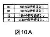
差分アドレス群93を圧縮する圧縮方法としては、図10Aに示す識別符号とその符号の意味との関係を示す圧縮規則にしたがうものとする。これにより、アドレス“0xA00000000”は、32ビット情報であることを示す識別符号“0b11”と元のアドレスとの組み合わせである符号語“11|0xA00000000”となる(なお、“|”は、標識符合と後続する情報を峻別するために便宜上表示したものでこれ自体は情報ではない。)。また、差分情報“0x00000004”は、4ビット情報であることを示す識別符号“0b00”と“0x4”との組み合わせである符号語“00|0x4”となる。このように、差分情報に対して圧縮処理を行うようにしたことで、圧縮度を大幅に向上させることができる。なお、受信側において伸長速度が受信速度を超える場合には、受信速度に応じて符号系列“0b01”、“0b10”及び“0b11”のいずれかを選択し、差分情報“0x00000004”を8ビット若しくは16ビットの情報に変換し、又は32ビットの情報としてそのまま用いることで、伸長速度が受信速度以下となるようにする。例えば、差分情報“0x00000004”が、4ビットで圧縮される場合には、符号語は、“00|0x4”でその符合長は標識符合を入れて6ビットになるが、符号語8ビット情報で圧縮される場合には、8ビットを示す識別符号“0b10”と0x04との組合せである符号語“10|0x04”すなわち符号語としての長さが10ビットの符号語に圧縮できる。
一方、分割データ群94を圧縮する圧縮方法としては、分割アドレス群93の圧縮に用いられた圧縮方法とは異なり、図10Bに示す識別符号とその符号の意味との関係を示す圧縮規則を用いる。これにより、分割データ“0x0012”は、識別符号“0b100”と“0x12”との組み合わせである符号語“100|0x12”に変換される。また、分割データ“0x1200”は、識別符号“0b101”と“0x12”との組み合わせである符号語“101|0x12”に変換される。また、分割データ“0x0000”は、符号語“0b000”に変換される。さらに、分割データ“0x1111”は、識別符号“0b110”と“0x11”との組み合わせである符号語“110|0x11”に変換される。
ビット数の多いデータを高効率で圧縮しようとすると多数の圧縮規則が必要となるが、データを分割してビット数の少ない分割データに対して圧縮処理を行うようにしたことで、少ない圧縮規則で、大幅に圧縮度を向上させることができる。なお、データ群の圧縮処理においても、受信側において伸長速度が受信速度を超える場合には、図10Bに示す符号系列“0b001”、“0b100”及び“0b111”のいずれかを用いて符号語を生成することにより、伸長速度を受信速度以下にすることができる。
以上のようにして得られた圧縮差分アドレス群95と圧縮分割データ群96とを結合することで、圧縮構成情報97が得られる。ここでは、構成情報90を構成するアドレスとデータの並び順と対応するように、1つの圧縮アドレスに対して2つの圧縮データが順番に並ぶように結合されている。ただし、結合順序は任意に変更可能である。
伸長工程は、上述した圧縮工程と逆の工程となる。即ち、圧縮構成情報97が、圧縮差分アドレス群95と圧縮分割データ群96とに分割され、夫々伸長処理される。得られた差分アドレス群93に対しては後処理として加算処理が行われ、分割データ群94に対しては後処理として結合処理が行われる。最後に、得られたアドレス群91とデータ群92を結合して、構成情報90が復元される。
ここで、図10A及び図10Bに示す圧縮規則について説明する。
図10Aの圧縮規則は、4つの規則により構成される。即ち、4ビットの符号拡張なしのデータに対しては、識別符号“0b00”と4ビットとの組み合わせを、8ビットの符号拡張なしのデータに対しては、符号系列“0b01”と8ビットデータとの組み合わせを、16ビットの符号拡張なしのデータに対しては、識別符号“0b10”と16ビットデータとの組み合わせを、32ビットの符号拡張なしのデータに対しては、識別符号“0b11”と32ビットデータとの組み合わせを夫々符号語として割り当てる。
また、図10Bの圧縮規則は、8つの規則により構成される。なお、同図におけるα及びβは、夫々任意の4ビットデータを表している。
図10Bの圧縮規則は、全てゼロのデータに対しては、識別符号“0b000”を、4ビットの符号拡張なしのデータに対しては、識別符号“0b001”と4ビットデータとの組み合わせを、“0x0α0β”からなるデータに対しては、識別符号“0b010”と8ビットデータとの組み合わせを、“0xα0β0”からなるデータに対しては、識別符号“0b011”と8ビットデータとの組み合わせを、8ビットの符号拡張なしのデータに対しては、識別符号“0b100”と8ビットデータとの組み合わせを、8ビットのゼロ詰めデータ(“0xαβ00”)に対しては、識別符号“0b100”と8ビットデータとの組み合わせを、上位と下位バイトが同じデータ(“0xαβαβ”)に対しては、識別符号“0b110”と8ビットデータとの組み合わせを、16ビットの符号拡張なしのデータに対しては、識別符号“0b111”と16ビットデータとの組み合わせを、夫々符号語として割り当てる。
図10Aに示す圧縮規則を差分アドレス群の93の圧縮処理に適用し、図10Bに示す圧縮規則を分割データ群94の圧縮処理に適用することで、圧縮率を大幅に向上させることができる。換言すると、差分アドレス群93及び分割データ群94の圧縮処理に、各々に適した独自の規則数、規則内容からなる圧縮規則を適用することで、圧縮率を大幅に向上させることができる。又、これらの符号規則を用いることで、伸長速度が受信速度を超えないように、符号語ごとに圧縮度を調整することができる。
次に、図11乃至図13を参照して、本発明の第3の形態に係る圧縮データ送受信装置に用いられるデータ圧縮装置及び圧縮データ受信装置について説明する。
第1の実施の形態に係るデータ圧縮装置は、受信側における伸長回路の伸長速度が受信回路の受信速度を超えることがないように、符号語単位で圧縮度を制御する。この技術を用いれば、伸長回路と受信回路との間にバッファ回路が存在する場合に、バッファ回路においてオーバフローが生じないように制御することが可能である。本実施の形態は、伸長回路と受信回路との間に、記憶容量の小さいバッファ回路を接続することを可能にするものである。
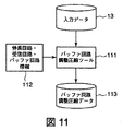
図11は、本実施の形態に係る圧縮データ送受信装置に用いられるデータ圧縮装置の概略構成を示すブロック図である。図示のデータ圧縮装置は、バッファ回路調整圧縮ツール111と、情報記憶部112とを有している。情報記憶部112には、受信側における伸長回路に関する情報、受信回路に関する情報の他、バッファ回路に関する情報も格納されている。伸長回路、受信回路、及びバッファ回路に関する情報は、例えば、伸長回路は1サイクルで何シンボルの伸長を行うか、受信回路は1サイクルで何バイト受信可能か、バッファ回路には何シンボル格納可能か、といった情報である。
バッファ回路調整圧縮ツール111の構成は、第1の実施の形態に係る調整圧縮ツール11と同様である。ただし、判定部における判定は、バッファ回路においてオーバフローが生じるか否かを基準として行われる。つまり、伸長回路の伸長速度が受信回路の受信速度を超える場合であっても、その速度差がバッファ回路により吸収できる範囲内であれば、圧縮度の高い符号語を圧縮度の低い符号語に置換することなくそのまま出力させる。こうして、バッファ回路調整圧縮ツール111は、伸長回路とバッファ回路の動作をエミュレートして、受信回路において受信できるか否かを判断しつつ、入力データ13を圧縮し、バッファ回路調整圧縮データ113として出力する。バッファ回路調整圧縮データ113は、図1の調整圧縮データ14に比べて、同じかそれよりも高い圧縮度を持つ。
図12に、本実施の形態に係る圧縮データ送受信装置に用いられる圧縮データ受信装置120の概略構成を示す。図示の圧縮データ受信装置120は、図3の圧縮データ受信装置30の構成(伸長回路31及び受信回路32)に加え、伸長回路31と受信回路32との間に接続された、記憶容量の比較的小さい省面積バッファ回路121とを有している。
伸長回路31は、バッファ回路調整圧縮データ113が入力されるとその圧縮データを伸長する。このとき伸長速度は、受信回路32の受信速度を超える場合があるが、その差は省面積バッファ回路121により吸収される。バッファ回路調整圧縮データ113は、省面積バッファ回路121でオーバフローが生じないように、符号語ごとに圧縮度が調整されているので、受信回路32で受信できないという事態は生じない。
図14に、伸長回路31の伸長速度の時間変化を示す。この図からは分かり難いが、伸長速度が受信速度を超える場合もある。
本実施の形態では、省面積バッファ回路121の記憶容量(サイズ)を制限することで、従来に比べて製造コストを低減することができる。また、伸長回路31の伸長速度が受信回路32の受信速度を超えないように、画一的に圧縮度を制御するのではなく、省面積バッファ回路121でオーバフローが生じないように圧縮度を制御するため、符号規則の自由度が高まり、第1の実施の形態の場合よりも圧縮データ全体の圧縮度を高めることが可能になる。
以上、本発明についていくつかの実施の形態に即して説明したが、本発明は、上記実施の形態に限定されるものではなく、本発明の範囲内で当業者であればなしうることが可能な各種変形、修正を含むことはもちろんである。
上記の実施形態の一部又は全部は、以下の付記のようにも記載されうるが、以下には限られない。
(付記1)
圧縮データを送信する送信装置と圧縮データを復元して受信する受信装置とを含む圧縮データ送受信装置であって、
前記送信装置は圧縮データを少なくとも1のデータ単位に対応して用意された互いに符合長の異なる複数の符合語の1つを前記受信装置の予め定められた受信速度を超えないように適応的に割当てて生成する圧縮手段を含む、
ことを特徴とする圧縮データ送受信装置。
(付記2)
前記複数の符号語は、
第1の圧縮度を与える第1の符号語と、前記第1の圧縮度よりも低い第2の圧縮度を与える第2の符号語である、
ことを特徴とする付記1に記載の圧縮データ送受信装置。
(付記3)
前記圧縮データを伸張し伸長データを生成する伸長回路と、
前記伸張データを前記受信速度で受信する受信回路とを含み、
前記伸長回路と前記受信回路はバッファ回路を介することなく又小容量のバッファ回路を介して接続されている、
ことを特徴とする付記1または2に記載の圧縮データ送受信装置。
(付記4)
前記圧縮手段は、前記圧縮データとして、再構成可能デバイスのための構成情報のアドレス部と対応するデータ部にそれぞれ含まれるアドレス情報及びデータ情報のそれぞれの系列であるアドレス情報系列及びデータ情報系列が圧縮された圧縮アドレス情報系列及び圧縮データ情報系列をそれぞれ生成する第1の圧縮手段及び第2の圧縮手段を含むこと、
を特徴とする付記3記載の圧縮データ送受信装置。
(付記5)
前記アドレス情報系列及び前記データ情報系列を圧縮に適した系列に変換する前処理を行い前処理済みアドレス情報系列及び前処理済みデータ情報系列を生成する第1及び第2の前処理手段を含み、前処理済みアドレス情報系列及び前処理済みデータ情報系列が前記第1の圧縮手段及び前記第2の圧縮手段に供給されること、
を特徴とする付記4記載の圧縮データ送受信装置。
(付記6)
前記第1の前処理部は、前記アドレス情報系列を構成する隣接アドレス情報の差分として前記前処理済みアドレス情報系列を生成することを特徴とする付記5記載の圧縮データ送受信装置。
(付記7)
前記伸張回路は、前記圧縮データとして、
前記圧縮アドレス情報系列及び圧縮データ情報系列をそれぞれ伸張し、伸張アドレス情報系列と伸張データ情報系列を生成するする第1及び第2の伸張手段とを含むことを特徴とする付記4、5又は6記載の圧縮データ送受信装置。
(付記8)
前記アドレス情報系列から前記前処理済みアドレス情報系列を生成させる前記第1の処理手段の処理の逆処理を前記伸張アドレス情報系列に行い後処理済みアドレス情報系列を生成する第1の後処理手段と、
前記データ情報系列から前記前処理済みデータ情報系列を生成させる前記第2の処理手段の処理の逆処理を前記伸張データ情報系列に行い後処理済みデータ情報系列を生成する第2の後処理手段とを含むこと、
を特徴とする付記7記載の圧縮データ送受信装置。
(付記9)
前記第1の後処理部は伸張アドレス情報系列を構成する隣接アドレス情報間で加算処理を行ない前記後処理済みアドレス情報系列を生成することを特徴とする付記8記載の圧縮データ送受信装置。
(付記10)
前記第1及び第2の伸長手段は、
各々独自の圧縮規則によって伸長を行う、
ことを特徴とする、付記7、8又は9に記載の圧縮データ送受信装置。
(付記11)
入力データを圧縮して圧縮データを生成するデータ圧縮方法であって、圧縮データを少なくとも1のデータ単位に対応して用意された互いに符合長の異なる複数の符合語の1つを適応的に割当てて生成し、前記圧縮データの圧縮度を符合語単位で調整することを特徴とするデータ圧縮方法。
(付記12)
前記複数の符合語の1つの割当は、前記圧縮データの符合長ができるだけ短く、かつ、前記圧縮データが伸張されたときのデータレートが所定値を越えないように割当てることを特徴とする付記11記載のデータ圧縮方法。
(付記13)
前記圧縮データの生成は、
入力データを前記複数の符合語のなかで符合長が最も短くなる符合語で逐次圧縮して予備圧縮データを生成し、
当該予備圧縮データを伸張したときのデータレートが前記所定値を超えるか否か判定し、
前記予備圧縮データを伸張したときのデータレートが前記所定値を超えると判定した場合に、前記予備圧縮データに含まれる対応する符号語を、より長い符合長の符号語に置換することを含むことを特徴とする付記12に記載のデータ圧縮方法。
(付記14)
前記所定値は、前記圧縮データを伸張した伸張データを受信する受信回路の受信速度である、
ことを特徴とする付記11、12又は13に記載のデータ圧縮方法。
(付記15)
圧縮データを少なくとも1のデータ単位に対応して用意された互いに符合長の異なる複数の符合語の1つを受信装置の予め定められた受信速度を超えないように適応的に割当てて生成する圧縮手段を含むデータ圧縮装置。
(付記16)
前記複数の符合語の1つの割当は、前記圧縮データの符合長ができるだけ短く、かつ、前記圧縮データが伸張されたときのデータレートが所定値を越えないように割当てることを特徴とする付記15記載のデータ圧縮装置。
(付記17)
前記少なくとも1のデータ単位に対応して用意された互いに符合長の異なる複数の符合語を記憶する符合記憶部手段を含む付記15又は16記載のデータ圧縮装置
(付記18)
前記データ圧縮手段は、
入力データを前記複数の符合語のなかで符合長が最も短くなる符合語で逐次圧縮する予備データ圧縮手段と、
当該予備圧縮データを伸張したときのデータレートが前記所定値を超えるか否か判定する判定手段と、
前記判定手段が前記予備圧縮データを伸張したときのデータレートが前記所定値を超えると判定した場合に、前記予備圧縮データに含まれる対応する符号語を、より長い符号長の符号語に置換する置換手段とを備える、
ことを特徴とする付記15、16又17記載のデータ圧縮装置。
(付記19)
前記所定値を記憶する情報記憶手段をさらに備えている、
ことを特徴とする付記17又は18記載のデータ圧縮装置。
(付記20)
圧縮データを伸張する伸張回路と、前記伸張回路によって伸張された伸張データを受信する受信回路とを備え、
前記伸張回路は、
少なくとも1のデータ単位に対応して用意された互いに符合長の異なる複数の符合語の1つを適応的に割当てられて構成された圧縮データを伸張する伸張手段を含み、
前記伸張回路と前記受信回路とはバッファ回路を介さずに又小容量バッファ回路を介しては接続されていることを特徴とする圧縮データ受信装置。
この出願は、2009年6月30日に出願された日本出願特願第2009−154931号を基礎とする優先権を主張し、その開示のすべてをここに取り込む。Hereinafter, embodiments of the present invention will be described in detail with reference to the drawings.
According to the embodiment, the input data is compressed by switching a plurality of pattern code words so as not to exceed a predetermined reception speed, so that the decompression speed on the reception side is hardly changed without changing the compression degree. Can be controlled. By performing compression control so that the decompression speed does not exceed the reception speed, the buffer circuit between the decompression circuit and the reception circuit can be made unnecessary, or the storage capacity of the buffer circuit can be greatly reduced, and compressed data can be received. The manufacturing cost of the apparatus can be reduced.
FIG. 1 shows a schematic configuration of a data compression apparatus used in the compressed data transmission / reception apparatus according to the first embodiment of the present invention. This data compression apparatus has an
The
A schematic configuration example of the
The
Usually, two types of codewords are prepared. Of these two types of codewords, the code length of one codeword is longer (or shorter) than the code length of the other codeword.
The
The determination unit 23 functions as a determination unit that determines whether or not the decompression speed (data rate) exceeds the reception speed (predetermined value) when the pre-compressed data from the
The
As described above, the
A codeword usually consists of an indicator code part followed by a digit part. In special cases, a codeword consists only of a sign code. As an example, consider a case where two code words are prepared for a data unit of 4 bits of continuous zero (“0b0000”). One code word is “0b0”, and the other code word is a code word “0b10000”. Here, 0b indicates binary display. The former is 1 bit as a code word, and the latter is 5 bits. The former 1-bit “0” indicates that the indicator code is 0 and that the digit value of the digit part is 0. The latter code word “0b10000” is composed of a sign code “1” and a digit part 4 bits “0000”.
The code word “0b1 ***” is assigned to 4-bit data “0b ***” other than continuous zero. This code word is composed of 5 bits, the sign code is “1”, and the digit part is composed of 4 bits “***”.
When compression is performed using this codeword, data in which zeros are continuous for 8 bits are compressed into compressed data of 2 bits, and data in which zeros are continuous for 16 bits are compressed into compressed data of 4 bits. When such compressed data is expanded, in the previous example, 2-bit compressed data becomes 8-bit expanded data, and in the later example, 4-bit compressed data becomes 16-bit expanded data. For example, assume that the decompression circuit decompresses 5 bits of compressed data per cycle, and the receiving circuit can receive 16 bits of decompressed data per cycle. At this time, if “0b00000” is input to the decompression circuit, the decompressed data becomes 20 consecutive bits of zero and exceeds the reception speed (16 bits) of the reception circuit, and therefore cannot be received by the reception circuit. In such a case, if the last 0 is replaced with “0b10000”, the input to the decompression circuit becomes “0b00001” and “0b0000 *” for two cycles. The decompression circuit decompresses “0b00001” and outputs 16-bit zero. At this time, the last 1 is not output because it indicates that the next 4 bits to be input are output as they are. Then, the first 4 bits of “0b0000 *” input in the next cycle are output as they are. As a result, the decompressed data output from the decompression circuit is zero that is 20 bits continuous.
The determination unit 23 determines, based on the information on the decompression speed of the decompression circuit and the reception speed of the reception circuit, whether or not the reception speed of the reception circuit is exceeded when the compressed data is decompressed. In other words, in the above example, the compressed data “0b00000” represents each codeword in which each digit has compressed the data “0000”. And
In the above example, two types of codewords, ie, a codeword with a high degree of compression (short code length) and a codeword with a low degree of compression (long code length) are used, but can be expanded to the same data. If there are, codewords having three or more different degrees of compression may be switched and used. By using codewords having three or more different degrees of compression, the decompression speed does not exceed the reception speed, and adjusted compressed data with a higher degree of compression can be generated.
The
Next, a compressed data receiving apparatus used for the compressed data transmitting / receiving apparatus according to the first embodiment of the present invention will be described with reference to FIG.
The compressed
The
The data decompressed in the
FIG. 4 shows changes over time in the decompression speed of the
Next, a compressed data transmitting / receiving apparatus according to the second embodiment of the present invention will be described with reference to FIGS. 5 to 10A and 10B.
The compressed data transmission / reception apparatus according to the present embodiment is a reconfigurable device typified by FPGA and its test apparatus. In this case, a data compression apparatus is used for the transmission circuit of the test apparatus that tests the reconfigurable device, and the reconfigurable device corresponding to the decompression circuit and the reception circuit constitutes the compressed data reception apparatus.
The input data is configuration information including a plurality of addresses and data corresponding to the plurality of addresses. Here, the address is information corresponding to the address where the corresponding data is to be stored, and the data is an arbitrary value to be stored at the address. Usually, an address is composed of a series of values, while data is an arbitrary value according to a format specified in a device (here, a reconfigurable device) that uses the data.
FIG. 5 shows a schematic configuration of the data compression apparatus according to the present embodiment. The data compression apparatus includes a dividing
FIG. 6 is a flowchart for explaining the operation of the data compression apparatus of FIG. The operation of the data compression apparatus in FIG. 5 will be described below with reference to FIG.
First, when the configuration information is input (step S11), the dividing
Next, the two preprocessing
Next, the two
Finally, the combining
Next, the configuration of a compressed data receiving apparatus corresponding to the data compressing apparatus in FIG. 5 will be described with reference to FIG.
The compressed data receiving apparatus in FIG. 7 includes a dividing
FIG. 8 is a flowchart for explaining the operation of the compressed data receiving apparatus of FIG. Hereinafter, the operation of the compressed data receiving apparatus of FIG. 7 will be described with reference to FIG.
First, when the compression configuration information from the data compression apparatus of FIG. 5 is input (step S21), the
Next, the two decompressing
Next, the two
Finally, the combining
The operations of the data compression apparatus in FIG. 5 and the compressed data reception apparatus in FIG. 7 will be further described with reference to FIGS. 9, 10A, and 10B.
FIG. 9 shows an example of changes in addresses and corresponding data in a compression step of compressing the
As shown in FIG. 9, in the compression process, the
On the other hand, in the expansion process, the
More specifically, the
When the
Next, as preprocessing for the
In general, the address information has relatively continuous values, but has different values, so that it is difficult to compress the address information. Therefore, by applying differentiation as preprocessing, a large amount of information having the same address difference is extracted. As a result, the compression rate of the address information can be greatly improved.
On the other hand, as preprocessing for the
Data used as setting information for a reconfigurable device having a repetitive configuration often takes a value with a minimum unit of decimal bits. Therefore, by applying 16-bit conversion as preprocessing, a large amount of information having the same value can be extracted. As a result, the compression rate of the data information can be greatly improved.
As a compression method for compressing the
On the other hand, as a compression method for compressing the divided
When trying to compress data with a large number of bits with high efficiency, a large number of compression rules are required, but by compressing the divided data with a small number of bits by dividing the data, a small number of compression rules are required. Thus, the degree of compression can be greatly improved. Even in the data group compression process, if the decompression speed exceeds the reception speed on the receiving side, the code word is converted using one of the code sequences “0b001”, “0b100”, and “0b111” shown in FIG. 10B. By generating, the decompression speed can be made lower than the reception speed.
The
The expansion process is the reverse of the compression process described above. That is, the
Here, the compression rules shown in FIGS. 10A and 10B will be described.
The compression rule in FIG. 10A is composed of four rules. That is, the combination of the identification code “0b00” and 4 bits is used for 4-bit data without code extension, and the code sequence “0b01” and 8-bit data is used for data without 8-bit code extension. For 16-bit data without code extension, a combination of identification code “0b10” and 16-bit data, and for data without 32-bit code extension, identification code “0b11”. And 32-bit data are assigned as codewords.
Further, the compression rule of FIG. 10B is configured by eight rules. In the figure, α and β each represent arbitrary 4-bit data.
In the compression rule of FIG. 10B, the identification code “0b000” is used for all-zero data, and the combination of the identification code “0b001” and 4-bit data is used for data without 4-bit code extension. For data consisting of “0x0α0β”, a combination of identification code “0b010” and 8-bit data is used. For data consisting of “0xα0β0”, a combination of identification code “0b011” and 8-bit data is used. A combination of the identification code “0b100” and 8-bit data is used for 8-bit data without code extension, and an identification code “0b100” and 8 are used for 8-bit zero-padded data (“0xαβ00”). For the combination of bit data, the upper and lower bytes have the same data (“0xαβαβ”) and the identification code “0b110” and 8 bits The combination of chromatography data for the 16-bit data without sign extension, the combination of the 16-bit data identification code "0b111", assigned as respective codewords.
By applying the compression rule shown in FIG. 10A to the compression process of the
Next, with reference to FIG. 11 to FIG. 13, a data compression apparatus and a compressed data reception apparatus used in the compressed data transmission / reception apparatus according to the third mode of the present invention will be described.
The data compression apparatus according to the first embodiment controls the degree of compression in codeword units so that the decompression speed of the decompression circuit on the receiving side does not exceed the reception speed of the reception circuit. If this technique is used, when a buffer circuit exists between the decompression circuit and the receiving circuit, it is possible to control the buffer circuit so that no overflow occurs. In this embodiment, a buffer circuit with a small storage capacity can be connected between the decompression circuit and the reception circuit.
FIG. 11 is a block diagram showing a schematic configuration of a data compression apparatus used in the compressed data transmission / reception apparatus according to the present embodiment. The illustrated data compression apparatus includes a buffer circuit
The configuration of the buffer circuit
FIG. 12 shows a schematic configuration of a compressed
When the buffer circuit adjustment compressed
FIG. 14 shows the change over time of the decompression speed of the
In this embodiment, by limiting the storage capacity (size) of the area saving
Although the present invention has been described with reference to some embodiments, the present invention is not limited to the above embodiments, and can be made by those skilled in the art within the scope of the present invention. Of course, various modifications and corrections are included.
A part or all of the above-described embodiment can be described as in the following supplementary notes, but is not limited thereto.
(Appendix 1)
A compressed data transmitting / receiving device including a transmitting device that transmits compressed data and a receiving device that restores and receives compressed data,
The transmitting apparatus adaptively applies one of a plurality of code words prepared corresponding to at least one data unit and having different code lengths so as not to exceed a predetermined receiving speed of the receiving apparatus. Including compression means to allocate and generate,
A compressed data transmitting / receiving apparatus characterized by the above.
(Appendix 2)
The plurality of codewords are:
A first codeword that provides a first degree of compression and a second codeword that provides a second degree of compression that is lower than the first degree of compression.
The compressed data transmitting / receiving apparatus according to appendix 1, wherein
(Appendix 3)
A decompression circuit that decompresses the compressed data and generates decompressed data;
A receiving circuit for receiving the decompressed data at the receiving speed,
The decompression circuit and the receiving circuit are connected not via a buffer circuit or via a small-capacity buffer circuit.
The compressed data transmitting / receiving apparatus according to appendix 1 or 2, characterized by the above.
(Appendix 4)
The compression means includes, as the compressed data, an address information sequence and a data information sequence, which are respective sequences of address information and data information included in the data portion corresponding to the address portion of the configuration information for the reconfigurable device, respectively. Including a first compression means and a second compression means for generating a compressed compressed address information sequence and a compressed data information sequence, respectively.
The compressed data transmitting / receiving apparatus according to supplementary note 3, characterized in that:
(Appendix 5)
First and second preprocessing means for performing preprocessing for converting the address information sequence and the data information sequence into a sequence suitable for compression and generating a preprocessed address information sequence and a preprocessed data information sequence; A preprocessed address information sequence and a preprocessed data information sequence are supplied to the first compression means and the second compression means;
The compressed data transmitting / receiving apparatus as set forth in appendix 4, characterized by:
(Appendix 6)
6. The compressed data transmitting / receiving apparatus according to claim 5, wherein the first preprocessing unit generates the preprocessed address information sequence as a difference between adjacent address information constituting the address information sequence.
(Appendix 7)
The decompression circuit, as the compressed data,
Additional notes 4, 5 or 6 including first and second decompressing means for decompressing the compressed address information sequence and the compressed data information sequence, respectively, and generating a decompressed address information sequence and a decompressed data information sequence. The compressed data transmitting / receiving apparatus as described.
(Appendix 8)
First post-processing means for generating a post-processed address information sequence by performing reverse processing of the first processing means for generating the pre-processed address information sequence from the address information sequence on the expanded address information sequence; ,
Second post-processing means for generating a post-processed data information sequence by performing reverse processing of the processing of the second processing means for generating the pre-processed data information sequence from the data information sequence, on the decompressed data information sequence; Including,
The compressed data transmitting / receiving apparatus according to appendix 7, wherein
(Appendix 9)
9. The compressed data transmitting / receiving apparatus according to claim 8, wherein the first post-processing unit performs addition processing between adjacent address information constituting the expanded address information series to generate the post-processed address information series.
(Appendix 10)
The first and second extension means include
Decompress each with its own compression rule,
The compressed data transmitting / receiving apparatus according to appendix 7, 8, or 9, characterized by the above.
(Appendix 11)
A data compression method for generating compressed data by compressing input data, and adaptively assigning one of a plurality of code words having different code lengths prepared corresponding to at least one data unit The data compression method is characterized in that the compression degree of the compressed data is adjusted in codeword units.
(Appendix 12)
The allocation of one of the plurality of code words is performed such that the code length of the compressed data is as short as possible and the data rate when the compressed data is expanded does not exceed a predetermined value. The data compression method described.
(Appendix 13)
The compressed data is generated by
The input data is sequentially compressed with a code word having the shortest code length among the plurality of code words to generate pre-compressed data,
Determining whether the data rate when the precompressed data is expanded exceeds the predetermined value;
Including replacing a corresponding codeword included in the preliminary compression data with a codeword having a longer code length when it is determined that the data rate when the preliminary compression data is expanded exceeds the predetermined value. The data compression method according to
(Appendix 14)
The predetermined value is a receiving speed of a receiving circuit that receives decompressed data obtained by decompressing the compressed data.
14. The data compression method according to
(Appendix 15)
Compression in which compressed data is generated by adaptively allocating one of a plurality of code words prepared corresponding to at least one data unit and having different code lengths so as not to exceed a predetermined reception speed of a receiving apparatus. A data compression apparatus including means.
(Appendix 16)
The one of the plurality of code words is assigned such that the code length of the compressed data is as short as possible and the data rate when the compressed data is expanded does not exceed a predetermined value. The data compression apparatus described.
(Appendix 17)
17. The data compression apparatus according to
(Appendix 18)
The data compression means includes
Preliminary data compression means for sequentially compressing input data with a code word having the shortest code length among the plurality of code words;
Determining means for determining whether or not a data rate when the preliminary compressed data is expanded exceeds the predetermined value;
When the determination unit determines that the data rate when the precompressed data is expanded exceeds the predetermined value, the corresponding codeword included in the precompressed data is replaced with a codeword having a longer code length. A replacement means,
18. The data compression apparatus according to
(Appendix 19)
An information storage means for storing the predetermined value;
The data compression apparatus according to appendix 17 or 18, characterized by the above.
(Appendix 20)
A decompression circuit for decompressing compressed data; and a reception circuit for receiving decompressed data decompressed by the decompression circuit;
The decompression circuit includes:
Decompression means for decompressing compressed data configured by adaptively allocating one of a plurality of code words having different code lengths prepared corresponding to at least one data unit;
2. The compressed data receiving apparatus according to claim 1, wherein the decompression circuit and the receiving circuit are connected not via a buffer circuit or via a small capacity buffer circuit.
This application claims the priority on the basis of Japanese application Japanese Patent Application No. 2009-154931 for which it applied on June 30, 2009, and takes in those the indications of all here.
Claims (20)
前記送信装置は、The transmitter is
再構成可能デバイスのための構成情報のアドレス部と対応するデータ部にそれぞれ含まれるアドレス情報及びデータ情報のそれぞれの系列であるアドレス情報系列及びデータ情報系列を、圧縮に適した系列に変換する前処理を行いそれぞれ前処理済みアドレス情報系列及び前処理済みデータ情報系列を生成する第1及び第2の前処理手段と、Before converting the address information series and the data information series, which are the series of address information and data information respectively included in the data part corresponding to the address part of the configuration information for the reconfigurable device, into a series suitable for compression First and second preprocessing means for performing processing and generating preprocessed address information sequences and preprocessed data information sequences, respectively;
前記前処理済みアドレス情報系列及び前記前処理済みデータ情報系列がそれぞれ供給されて圧縮された圧縮アドレス情報系列及び圧縮データ情報系列をそれぞれ生成する第1の圧縮手段及び第2の圧縮手段を含み、A first compression unit and a second compression unit for generating a compressed address information sequence and a compressed data information sequence, respectively, which are compressed by being supplied with the preprocessed address information sequence and the preprocessed data information sequence, respectively;
前記第1の圧縮手段及び前記第2の圧縮手段は、それぞれ、少なくとも1の符合単位に対応して用意された互いに符合長の異なる複数の符合語の1つを前記受信装置の予め定められた受信速度を超えないように適応的に割当てる、Each of the first compression means and the second compression means is configured to determine one of a plurality of code words prepared corresponding to at least one code unit and having different code lengths from each other. Adaptively allocate so as not to exceed the receiving speed,
ことを特徴とする圧縮データ送受信装置。A compressed data transmitting / receiving apparatus characterized by the above.
前記圧縮アドレス情報系列及び前記圧縮データ情報系列をそれぞれ伸張し,伸張アドレス情報系列と伸張データ情報系列を生成するする第1及び第2の伸張手段とを含むことを特徴とする請求項1、2又は3記載の圧縮データ送受信装置。3. The first and second decompressing means for decompressing the compressed address information sequence and the compressed data information sequence, respectively, and generating a decompressed address information sequence and a decompressed data information sequence, respectively. Or the compressed data transmitting / receiving apparatus according to 3;
前記データ情報系列から前記前処理済みデータ情報系列を生成させる前記第2の処理手段の処理の逆処理を前記伸張データ情報系列に行い後処理済みデータ情報系列を生成する第2の後処理手段とを含むこと、Second post-processing means for generating a post-processed data information sequence by performing reverse processing of the processing of the second processing means for generating the pre-processed data information sequence from the data information sequence, on the decompressed data information sequence; Including,
を特徴とする請求項1、2、3、又は4記載の圧縮データ送受信装置。The compressed data transmitting / receiving apparatus according to claim 1, 2, 3, or 4.
各々独自の圧縮規則によって伸長を行う、 Decompress each with its own compression rule,
ことを特徴とする、請求項4、5又は6に記載の圧縮データ送受信装置。The compressed data transmitting / receiving apparatus according to claim 4, 5 or 6.
再構成可能デバイスのための構成情報のアドレス部と対応するデータ部にそれぞれ含まれるアドレス情報及びデータ情報のそれぞれの系列であるアドレス情報系列及びデータ情報系列を、圧縮に適した系列に変換する前処理を行いそれぞれ前処理済みアドレス情報系列及び前処理済みデータ情報系列を生成し、Before converting the address information series and the data information series, which are the series of address information and data information respectively included in the data part corresponding to the address part of the configuration information for the reconfigurable device, into a series suitable for compression Process to generate pre-processed address information series and pre-processed data information series,
前記前処理済みアドレス情報系列及び前記前処理済みデータ情報系列がそれぞれ供給されて少なくとも1の符合単位に対応して用意された互いに符合長の異なる複数の符合語の1つを前記受信装置の予め定められた受信速度を超えないように適応的に割当てて圧縮アドレス情報系列及び圧縮データ情報系列をそれぞれ生成する、Each of the preprocessed address information sequence and the preprocessed data information sequence is supplied, and one of a plurality of code words having different code lengths prepared corresponding to at least one code unit is stored in advance in the receiving apparatus. A compressed address information sequence and a compressed data information sequence are generated by adaptively allocating so as not to exceed a predetermined reception rate,
ことを特徴とする情報圧縮方法。An information compression method characterized by the above.
当該予備圧縮情報を伸張したときの伸張速度が前記所定値を超えるか否か判定し、Determining whether the decompression speed when decompressing the preliminary compression information exceeds the predetermined value;
前記予備圧縮情報を伸張したときの伸張速度が前記所定値を超えると判定した場合に、前記予備圧縮情報に含まれる対応する符号語を、より長い符合長の符号語に置換することを含むことを特徴とする請求項8又は9に記載の情報圧縮方法。Including replacing a corresponding codeword included in the preliminary compression information with a codeword having a longer code length when it is determined that the expansion speed when the preliminary compression information is expanded exceeds the predetermined value. 10. The information compression method according to claim 8 or 9, wherein:
再構成可能デバイスのための構成情報のアドレス部と対応するデータ部にそれぞれ含まれるアドレス情報及びデータ情報のそれぞれの系列であるアドレス情報系列及びデータ情報系列を、圧縮に適した系列に変換する前処理を行いそれぞれ前処理済みアドレス情報系列及び前処理済みデータ情報系列を生成する第1及び第2の前処理手段と、Before converting the address information series and the data information series, which are the series of address information and data information respectively included in the data part corresponding to the address part of the configuration information for the reconfigurable device, into a series suitable for compression First and second preprocessing means for performing processing and generating preprocessed address information sequences and preprocessed data information sequences, respectively;
前記前処理済みアドレス情報系列及び前記前処理済みデータ情報系列がそれぞれ供給されて圧縮された圧縮アドレス情報系列及び圧縮データ情報系列をそれぞれ生成する第1の圧縮手段及び第2の圧縮手段を含み、A first compression unit and a second compression unit for generating a compressed address information sequence and a compressed data information sequence, respectively, which are compressed by being supplied with the preprocessed address information sequence and the preprocessed data information sequence, respectively;
前記第1の圧縮手段及び前記第2の圧縮手段は、それぞれ、少なくとも1の符合単位に対応して用意された互いに符合長の異なる複数の符合語の1つを前記受信装置の予め定められた受信速度を超えないように適応的に割当てる、Each of the first compression means and the second compression means is configured to determine one of a plurality of code words prepared corresponding to at least one code unit and having different code lengths from each other. Adaptively allocate so as not to exceed the receiving speed,
ことを特徴とする圧縮データ送信装置。A compressed data transmission apparatus characterized by the above.
当該予備圧縮情報を伸張したときの伸張速度が前記所定値を超えるか否か判定する判定手段と、Determination means for determining whether or not the expansion speed when the preliminary compression information is expanded exceeds the predetermined value;
前記判定手段が前記予備圧縮情報を伸張したときの伸張速度が前記所定値を超えると判定した場合に、前記前記予備圧縮情報に含まれる対応する符号語を、より長い符号長の符号語に置換する置換手段とを備える、When the determination unit determines that the expansion speed when the preliminary compression information is expanded exceeds the predetermined value, the corresponding codeword included in the preliminary compression information is replaced with a codeword having a longer code length. Replacement means for
ことを特徴とする請求項11又は12記載の圧縮データ送信装置。13. The compressed data transmitting apparatus according to claim 11 or 12,
前記圧縮アドレス情報系列及び前記圧縮データ情報系列をそれぞれ伸張し,伸張アドレス情報系列と伸張データ情報系列を生成するする第1及び第2の伸張手段とを含むことを特徴とする請求項11、12、又は13記載の圧縮データ送信装置。13. The first and second decompressing means for decompressing the compressed address information sequence and the compressed data information sequence, respectively, and generating a decompressed address information sequence and a decompressed data information sequence, respectively. Or the compressed data transmission device according to 13.
前記アドレス情報系列から前記前処理済みアドレス情報系列を生成させる前記第1の処理手段の処理の逆処理を前記伸張アドレス情報系列に行い後処理済みアドレス情報系列を生成する第1の後処理手段と、First post-processing means for generating a post-processed address information sequence by performing reverse processing of the first processing means for generating the pre-processed address information sequence from the address information sequence on the expanded address information sequence; ,
前記データ情報系列から前記前処理済みデータ情報系列を生成させる前記第2の処理手段の処理の逆処理を前記伸張データ情報系列に行い後処理済みデータ情報系列を生成する第2の後処理手段とを含むこと、Second post-processing means for generating a post-processed data information sequence by performing reverse processing of the processing of the second processing means for generating the pre-processed data information sequence from the data information sequence, on the decompressed data information sequence; Including,
を特徴とする請求項14記載の圧縮データ送信装置。The compressed data transmitting apparatus according to claim 14.
ことを特徴とする、請求項14又は15に記載の圧縮データ送信装置。The compressed data transmission apparatus according to claim 14 or 15, characterized in that:
前記送信装置は圧縮データを少なくとも1の符号化対象のデータ単位に対応して用意された互いに符合長の異なる複数の符合語の1つを前記受信装置の予め定められた受信速度を超えないように適応的に割当てて生成する圧縮手段を含む、The transmitting apparatus does not exceed one predetermined reception speed of the receiving apparatus by adding one of a plurality of code words prepared corresponding to at least one encoding target data unit and having different code lengths to each other. Including compression means for adaptively assigning and generating
ことを特徴とする圧縮データ送受信装置。A compressed data transmitting / receiving apparatus characterized by the above.
Priority Applications (1)
| Application Number | Priority Date | Filing Date | Title |
|---|---|---|---|
| JP2011520849A JP5146708B2 (en) | 2009-06-30 | 2010-06-01 | Compressed data transmission / reception device, data compression device, compressed data reception device, and data compression method |
Applications Claiming Priority (4)
| Application Number | Priority Date | Filing Date | Title |
|---|---|---|---|
| JP2009154931 | 2009-06-30 | ||
| JP2009154931 | 2009-06-30 | ||
| JP2011520849A JP5146708B2 (en) | 2009-06-30 | 2010-06-01 | Compressed data transmission / reception device, data compression device, compressed data reception device, and data compression method |
| PCT/JP2010/059581 WO2011001790A1 (en) | 2009-06-30 | 2010-06-01 | Compressed data transmission/reception device, data compression device, compressed data reception device, and data compression method |
Publications (2)
| Publication Number | Publication Date |
|---|---|
| JPWO2011001790A1 JPWO2011001790A1 (en) | 2012-12-13 |
| JP5146708B2 true JP5146708B2 (en) | 2013-02-20 |
Family
ID=43410870
Family Applications (1)
| Application Number | Title | Priority Date | Filing Date |
|---|---|---|---|
| JP2011520849A Expired - Fee Related JP5146708B2 (en) | 2009-06-30 | 2010-06-01 | Compressed data transmission / reception device, data compression device, compressed data reception device, and data compression method |
Country Status (3)
| Country | Link |
|---|---|
| US (1) | US9160361B2 (en) |
| JP (1) | JP5146708B2 (en) |
| WO (1) | WO2011001790A1 (en) |
Families Citing this family (2)
| Publication number | Priority date | Publication date | Assignee | Title |
|---|---|---|---|---|
| KR102159279B1 (en) * | 2014-05-29 | 2020-09-23 | 한국전자통신연구원 | Method and apparatus for generating frame for error correction |
| US10531099B2 (en) | 2016-09-30 | 2020-01-07 | The Mitre Corporation | Systems and methods for distributed quantization of multimodal images |
Citations (3)
| Publication number | Priority date | Publication date | Assignee | Title |
|---|---|---|---|---|
| JPH0614314A (en) * | 1992-06-25 | 1994-01-21 | Mitsubishi Electric Corp | High efficiency encoder |
| JP2000341535A (en) * | 1999-05-31 | 2000-12-08 | Canon Inc | Image communication control method and image communication apparatus to which the method is applied |
| JP2008152409A (en) * | 2006-12-15 | 2008-07-03 | Renesas Technology Corp | Semiconductor integrated circuit |
Family Cites Families (5)
| Publication number | Priority date | Publication date | Assignee | Title |
|---|---|---|---|---|
| JP2970633B2 (en) | 1997-11-21 | 1999-11-02 | 日本電気株式会社 | ATM controller |
| JP2000299664A (en) | 1999-04-14 | 2000-10-24 | Casio Comput Co Ltd | Data processing device and storage medium storing data processing program |
| JP2001148858A (en) | 1999-11-18 | 2001-05-29 | Sony Corp | Image information conversion apparatus and image information conversion method |
| KR100440952B1 (en) * | 2001-08-04 | 2004-07-21 | 삼성전자주식회사 | Bit rate changing method through change of codeword of compressed image bit stream and apparatus therefor |
| US7391717B2 (en) * | 2003-06-30 | 2008-06-24 | Microsoft Corporation | Streaming of variable bit rate multimedia content |
-
2010
- 2010-06-01 US US13/379,271 patent/US9160361B2/en not_active Expired - Fee Related
- 2010-06-01 JP JP2011520849A patent/JP5146708B2/en not_active Expired - Fee Related
- 2010-06-01 WO PCT/JP2010/059581 patent/WO2011001790A1/en not_active Ceased
Patent Citations (3)
| Publication number | Priority date | Publication date | Assignee | Title |
|---|---|---|---|---|
| JPH0614314A (en) * | 1992-06-25 | 1994-01-21 | Mitsubishi Electric Corp | High efficiency encoder |
| JP2000341535A (en) * | 1999-05-31 | 2000-12-08 | Canon Inc | Image communication control method and image communication apparatus to which the method is applied |
| JP2008152409A (en) * | 2006-12-15 | 2008-07-03 | Renesas Technology Corp | Semiconductor integrated circuit |
Also Published As
| Publication number | Publication date |
|---|---|
| WO2011001790A1 (en) | 2011-01-06 |
| US20120099626A1 (en) | 2012-04-26 |
| JPWO2011001790A1 (en) | 2012-12-13 |
| US9160361B2 (en) | 2015-10-13 |
Similar Documents
| Publication | Publication Date | Title |
|---|---|---|
| KR101737294B1 (en) | Methods and devices for source-coding and decoding of data involving symbol compression | |
| EP4012928B1 (en) | Methods, devices and systems for semantic-value data compression and decompression | |
| US8125357B1 (en) | Deflate decompressor | |
| JP2020141402A (en) | Data compression methods and equipment | |
| US7688233B2 (en) | Compression for deflate algorithm | |
| RU2630750C1 (en) | Device and method for encoding and decoding initial data | |
| JP6045123B2 (en) | Encoder, decoder and method | |
| KR101782278B1 (en) | Coding and decoding of spectral peak positions | |
| JP2013138422A (en) | System and method for compressing stream of integer-valued data | |
| EP3991303B1 (en) | Features of range asymmetric number system encoding and decoding | |
| JP5146708B2 (en) | Compressed data transmission / reception device, data compression device, compressed data reception device, and data compression method | |
| CN105791819B (en) | The decompression method and device of a kind of frame compression method of image, image | |
| KR20150126858A (en) | Entropy modifier and method | |
| KR102706107B1 (en) | Device of compressing data, system of compressing data and method of compressing data | |
| KR102296153B1 (en) | Dedicated arithmetic encoding instruction | |
| JPH08186723A (en) | Encoder for image processing device | |
| US10491241B1 (en) | Data compression scheme utilizing a repetitive value within the data stream | |
| KR101632116B1 (en) | Binary data compression and restoration method and apparatus | |
| CN111384962A (en) | Data compression/decompression device and data compression method | |
| JP2023170314A (en) | Data processing method and data processing device | |
| US8872537B2 (en) | Semiconductor integrated circuit, circuit testing system, circuit testing unit, and circuit test method | |
| JP4011580B2 (en) | Image data transmission system | |
| JP5499700B2 (en) | Information compression apparatus, information restoration apparatus, information compression method, information restoration method, and processing program therefor | |
| KR101676420B1 (en) | Data compression and restoration method and apparatus | |
| CN111384964A (en) | Data compression/decompression device and data compression method |
Legal Events
| Date | Code | Title | Description |
|---|---|---|---|
| TRDD | Decision of grant or rejection written | ||
| A01 | Written decision to grant a patent or to grant a registration (utility model) |
Free format text: JAPANESE INTERMEDIATE CODE: A01 Effective date: 20121031 |
|
| A61 | First payment of annual fees (during grant procedure) |
Free format text: JAPANESE INTERMEDIATE CODE: A61 Effective date: 20121113 |
|
| R150 | Certificate of patent or registration of utility model |
Ref document number: 5146708 Country of ref document: JP Free format text: JAPANESE INTERMEDIATE CODE: R150 Free format text: JAPANESE INTERMEDIATE CODE: R150 |
|
| FPAY | Renewal fee payment (event date is renewal date of database) |
Free format text: PAYMENT UNTIL: 20151207 Year of fee payment: 3 |
|
| LAPS | Cancellation because of no payment of annual fees |