JP5149060B2 - 両歯面噛合式歯車検査装置 - Google Patents
両歯面噛合式歯車検査装置 Download PDFInfo
- Publication number
- JP5149060B2 JP5149060B2 JP2008103312A JP2008103312A JP5149060B2 JP 5149060 B2 JP5149060 B2 JP 5149060B2 JP 2008103312 A JP2008103312 A JP 2008103312A JP 2008103312 A JP2008103312 A JP 2008103312A JP 5149060 B2 JP5149060 B2 JP 5149060B2
- Authority
- JP
- Japan
- Prior art keywords
- gear
- inspected
- power spectrum
- waveform
- axis
- Prior art date
- Legal status (The legal status is an assumption and is not a legal conclusion. Google has not performed a legal analysis and makes no representation as to the accuracy of the status listed.)
- Expired - Fee Related
Links
- 238000007689 inspection Methods 0.000 title claims description 14
- 235000000621 Bidens tripartita Nutrition 0.000 title description 3
- 240000004082 Bidens tripartita Species 0.000 title description 3
- 208000006637 fused teeth Diseases 0.000 title description 3
- 238000001228 spectrum Methods 0.000 claims description 75
- 238000005070 sampling Methods 0.000 claims description 11
- 238000010586 diagram Methods 0.000 description 8
- 238000001514 detection method Methods 0.000 description 4
- 238000005259 measurement Methods 0.000 description 4
- 239000003638 chemical reducing agent Substances 0.000 description 2
- 238000000354 decomposition reaction Methods 0.000 description 1
- 239000000284 extract Substances 0.000 description 1
- 238000005096 rolling process Methods 0.000 description 1
- 230000009466 transformation Effects 0.000 description 1
- 230000001131 transforming effect Effects 0.000 description 1
Images




Landscapes
- Testing Of Devices, Machine Parts, Or Other Structures Thereof (AREA)
Description
請求項2に係る発明は、前記フーリエ変換された周波数軸パワースペクトルから、マスタ歯車1回転周期のパワースペクトル、被検査歯車1回転周期のパワースペクトル、及び被検査歯車歯数周期パワースペクトルのみを抽出して二次周波数軸パワースペクトルを生成し、該二次周波数軸パワースペクトルを逆フーリエ変換してマスタ歯車と被検査歯車との時間軸間変動二次波形を生成し、検出器で検出した時間軸間変動原波形から前記時間軸間変動二次波形を減算して時間軸間変動三次波形を生成し、該時間軸間変動三次波形から被検査歯車の打痕値を求めるようにしたものである。
請求項3に係る発明は、前記時間軸間変動三次波形から被検査歯車の打痕部のパルス列を求め、パルスモータに所定の駆動パルスを発して前記打痕部がマーキング位置となるように被検査歯車を回転させるようにしたものである。
請求項2に係る発明は、時間軸間変動原波形からマスタ歯車の歯溝の振れ、被検査歯車の歯溝の振れ、被検査歯車の1ピッチ噛み合い誤差の波形を取り除くようにしたので、被検査歯車の打痕値を正確に求めることができる。
請求項3に係る発明は、被検査歯車に発生している打痕部のパルス列を求め、パルスモータに所定の駆動パルスを発するようにしたので、前記打痕部をマーキング位置に正確に位置決めすることができる。
2 フレーム
3 スピンドル
4 パルスモータ
5 減速機
7 スライダ
8 支持軸
9 シリンダ
10 ばね
12 噛合検出器
13 軸間距離検出器
16 マスタ歯車
17 被検査歯車
20 制御部
21 サンプリング数・駆動パルス数設定部
22 時間軸間変動波形生成部
23 シリンダ駆動部
24 モータ制御部
25 周波数軸パワースペクトル生成部
26 種類別振幅演算部
27 判定部
28 判定値設定部
29 打痕位置演算部
30 マーキング作動部
A1 時間軸間変動原波形
A1−1 マスタ歯車の歯溝振れ波形
A1−2 被検査歯車の歯溝振れ波形
A1−3 被検査歯車の1ピッチ噛み合い誤差波形
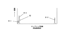
B1 周波数軸パワースペクトル
B1−1 マスタ歯車1回転周期のパワースペクトル
B1−2 被検査歯車1回転周期のパワースペクトル
B1−3 被検査歯車歯数周期パワースペクトル
B2 二次周波数軸パワースペクトル
Claims (3)
- 異なる歯数のマスタ歯車(16)と被検査歯車(17)とを接近方向に押圧付勢して互いに噛合させ、前記マスタ歯車(16)又は被検査歯車(17)をパルスモータ(4)によって回転させ、前記マスタ歯車(16)と被検査歯車(17)との軸間変動量を検出する検出器(13)を設け、被検査歯車(17)の規定整数回転における前記検出器(13)から入力するサンプリング数を一定とし、前記検出器(13)で検出したマスタ歯車(16)と被検査歯車(17)との時間軸間変動原波形(A1)をフーリエ変換して周波数軸パワースペクトル(B1)に分解することにより、マスタ歯車1回転周期のパワースペクトル(B1−1)、被検査歯車1回転周期のパワースペクトル(B1−2)、及び被検査歯車歯数周期のパワースペクトル(B1−3)を周波数別に生成し、前記マスタ歯車1回転周期のパワースペクトル(B1−1)の振幅をマスタ歯車(16)の歯溝の振れ、前記被検査歯車1回転周期のパワースペクトル(B1−2)の振幅を被検査歯車(17)の歯溝の振れ、前記被検査歯車歯数周期のパワースペクトル(B1−3)の振幅を被検査歯車(17)の1ピッチ噛み合い誤差としたことを特徴とする両歯面噛合式歯車検査装置。
- フーリエ変換された周波数軸パワースペクトル(B1)から、マスタ歯車1回転周期のパワースペクトル(B1−1)、被検査歯車1回転周期のパワースペクトル(B1−2)、及び被検査歯車歯数周期のパワースペクトル(B1−3)のみを抽出して二次周波数軸パワースペクトル(B2)を生成し、該二次周波数軸パワースペクトル(B2)を逆フーリエ変換してマスタ歯車(16)と被検査歯車(17)との時間軸間変動二次波形(A2)を生成し、検出器(13)で検出した時間軸間変動原波形(A1)から前記時間軸間変動二次波形(A2)を減算して時間軸間変動三次波形(A3)を生成し、該時間軸間変動三次波形(A3)から被検査歯車(17)の打痕値を求めたことを特徴とする請求項1記載の両歯面噛合式歯車検査装置。
- 時間軸間変動三次波形(A3)から被検査歯車(17)の打痕部のパルス列を求め、パルスモータ(4)に所定の駆動パルスを発して前記打痕部がマーキング位置となるように被検査歯車(17)を回転させたことを特徴とする請求項2記載の両歯面噛合式歯車検査装置。
Priority Applications (1)
| Application Number | Priority Date | Filing Date | Title |
|---|---|---|---|
| JP2008103312A JP5149060B2 (ja) | 2008-04-11 | 2008-04-11 | 両歯面噛合式歯車検査装置 |
Applications Claiming Priority (1)
| Application Number | Priority Date | Filing Date | Title |
|---|---|---|---|
| JP2008103312A JP5149060B2 (ja) | 2008-04-11 | 2008-04-11 | 両歯面噛合式歯車検査装置 |
Publications (2)
| Publication Number | Publication Date |
|---|---|
| JP2009250954A JP2009250954A (ja) | 2009-10-29 |
| JP5149060B2 true JP5149060B2 (ja) | 2013-02-20 |
Family
ID=41311809
Family Applications (1)
| Application Number | Title | Priority Date | Filing Date |
|---|---|---|---|
| JP2008103312A Expired - Fee Related JP5149060B2 (ja) | 2008-04-11 | 2008-04-11 | 両歯面噛合式歯車検査装置 |
Country Status (1)
| Country | Link |
|---|---|
| JP (1) | JP5149060B2 (ja) |
Cited By (1)
| Publication number | Priority date | Publication date | Assignee | Title |
|---|---|---|---|---|
| EP4042131A1 (en) * | 2019-10-09 | 2022-08-17 | The Gleason Works | Analytic system and method for testing gears |
Families Citing this family (3)
| Publication number | Priority date | Publication date | Assignee | Title |
|---|---|---|---|---|
| CN102998115B (zh) * | 2012-11-26 | 2015-05-20 | 合肥邦立电子股份有限公司 | 一种制备abs传感器检测工装的专用abs齿轮检测装置 |
| CN102998114B (zh) * | 2012-11-26 | 2015-12-09 | 合肥邦立电子股份有限公司 | 一种可移动式abs齿轮检测装置 |
| JP7191457B2 (ja) * | 2018-07-05 | 2022-12-19 | 株式会社Subaru | マスターギヤ、該マスターギヤを備えた打痕検査装置及び該マスターギヤを用いた打痕検査方法 |
Family Cites Families (1)
| Publication number | Priority date | Publication date | Assignee | Title |
|---|---|---|---|---|
| JPS5356057A (en) * | 1976-10-30 | 1978-05-22 | Toyota Motor Co Ltd | Gear mesh testing method |
-
2008
- 2008-04-11 JP JP2008103312A patent/JP5149060B2/ja not_active Expired - Fee Related
Cited By (1)
| Publication number | Priority date | Publication date | Assignee | Title |
|---|---|---|---|---|
| EP4042131A1 (en) * | 2019-10-09 | 2022-08-17 | The Gleason Works | Analytic system and method for testing gears |
Also Published As
| Publication number | Publication date |
|---|---|
| JP2009250954A (ja) | 2009-10-29 |
Similar Documents
| Publication | Publication Date | Title |
|---|---|---|
| TWI518310B (zh) | 齒輪精度的檢測方法 | |
| US7784345B2 (en) | Device and method for combined testing of gears | |
| JP5149060B2 (ja) | 両歯面噛合式歯車検査装置 | |
| DE102011079384B4 (de) | Verfahren und Vorrichtung zum Bestimmen einer Qualität einer Getriebeanordnung aus mindestens zwei Getrieberädern | |
| CN102305712A (zh) | 等时间间隔采样下的非均速传动系统误差溯源方法 | |
| Pueo et al. | A review of tangential composite and radial composite gear inspection | |
| CN105300691B (zh) | 基于最佳安装距的锥齿轮传动误差测量方法 | |
| EP3301455A2 (en) | Angular velocity measuring device and relative angular velocity measuring device | |
| DE3123489A1 (de) | Verfahren zur messung der rundheitsabweichungen von rotationskoerpern und einrichtungen zur durchfuehrung des verfahrens | |
| US7607236B1 (en) | Functional rolling master gear, spindle, and arbor compensation | |
| US5016471A (en) | Test method and testing device for detecting any faults, or inaccuracies, in splined wheels or objects with similar profiles | |
| KR20170120312A (ko) | 사이클로이드 기어의 치형 측정 장치 및 방법 | |
| CN103424084A (zh) | 基于二维激光位移传感器的砂轮三维形貌测量方法 | |
| JP5836186B2 (ja) | 歯車検査装置及び方法 | |
| CN105699683A (zh) | 一种汽轮机转速测量方法及系统 | |
| Wang et al. | Condition monitoring of multistage printing presses | |
| CN203928948U (zh) | 蜗轮蜗杆啮合径向跳动量检测仪 | |
| JP2978377B2 (ja) | ギヤの歯溝の振れ測定装置 | |
| CN105651512A (zh) | 一种汽车驱动桥主减齿轮包块检测方法 | |
| JP3720704B2 (ja) | 歯車の偏心等の誤差測定方法およびその装置 | |
| CN106217131A (zh) | 攻丝过程同步误差测量方法 | |
| JP3586997B2 (ja) | 傘歯車の歯形評価方法およびその装置 | |
| DE102005042278B4 (de) | Evolventischer Prüfkörper mit überlagerten periodischen Strukturen, auch Wellen genannt, zur Beurteilung von Messgeräten und Werkzeugmaschinen | |
| JPH0625707B2 (ja) | 歯車の歯振れ測定装置 | |
| DE10012158B4 (de) | Verfahren zum Feststellen und Anzeigen von Verzahnungsfehlern sowie Messvorrichtung zur Qualitätsprüfung von Zahnrädern und/oder Zahnwellen |
Legal Events
| Date | Code | Title | Description |
|---|---|---|---|
| A621 | Written request for application examination |
Free format text: JAPANESE INTERMEDIATE CODE: A621 Effective date: 20110408 |
|
| A977 | Report on retrieval |
Free format text: JAPANESE INTERMEDIATE CODE: A971007 Effective date: 20120717 |
|
| A131 | Notification of reasons for refusal |
Free format text: JAPANESE INTERMEDIATE CODE: A131 Effective date: 20120807 |
|
| A521 | Request for written amendment filed |
Free format text: JAPANESE INTERMEDIATE CODE: A523 Effective date: 20121002 |
|
| TRDD | Decision of grant or rejection written | ||
| A01 | Written decision to grant a patent or to grant a registration (utility model) |
Free format text: JAPANESE INTERMEDIATE CODE: A01 Effective date: 20121030 |
|
| A61 | First payment of annual fees (during grant procedure) |
Free format text: JAPANESE INTERMEDIATE CODE: A61 Effective date: 20121129 |
|
| R150 | Certificate of patent or registration of utility model |
Ref document number: 5149060 Country of ref document: JP Free format text: JAPANESE INTERMEDIATE CODE: R150 Free format text: JAPANESE INTERMEDIATE CODE: R150 |
|
| FPAY | Renewal fee payment (event date is renewal date of database) |
Free format text: PAYMENT UNTIL: 20151207 Year of fee payment: 3 |
|
| R250 | Receipt of annual fees |
Free format text: JAPANESE INTERMEDIATE CODE: R250 |
|
| R250 | Receipt of annual fees |
Free format text: JAPANESE INTERMEDIATE CODE: R250 |
|
| R250 | Receipt of annual fees |
Free format text: JAPANESE INTERMEDIATE CODE: R250 |
|
| R250 | Receipt of annual fees |
Free format text: JAPANESE INTERMEDIATE CODE: R250 |
|
| R250 | Receipt of annual fees |
Free format text: JAPANESE INTERMEDIATE CODE: R250 |
|
| R250 | Receipt of annual fees |
Free format text: JAPANESE INTERMEDIATE CODE: R250 |
|
| LAPS | Cancellation because of no payment of annual fees |