JP5153473B2 - Glow system, control unit, and glow plug output control method - Google Patents
Glow system, control unit, and glow plug output control method Download PDFInfo
- Publication number
- JP5153473B2 JP5153473B2 JP2008163586A JP2008163586A JP5153473B2 JP 5153473 B2 JP5153473 B2 JP 5153473B2 JP 2008163586 A JP2008163586 A JP 2008163586A JP 2008163586 A JP2008163586 A JP 2008163586A JP 5153473 B2 JP5153473 B2 JP 5153473B2
- Authority
- JP
- Japan
- Prior art keywords
- potential
- gnd
- glow
- ground
- supply voltage
- Prior art date
- Legal status (The legal status is an assumption and is not a legal conclusion. Google has not performed a legal analysis and makes no representation as to the accuracy of the status listed.)
- Expired - Fee Related
Links
- 238000000034 method Methods 0.000 title claims description 11
- 238000006073 displacement reaction Methods 0.000 claims description 22
- 101150042711 adc2 gene Proteins 0.000 claims description 21
- 101100162020 Mesorhizobium japonicum (strain LMG 29417 / CECT 9101 / MAFF 303099) adc3 gene Proteins 0.000 claims description 15
- 238000005259 measurement Methods 0.000 claims description 15
- 101100434411 Saccharomyces cerevisiae (strain ATCC 204508 / S288c) ADH1 gene Proteins 0.000 claims description 7
- 101150102866 adc1 gene Proteins 0.000 claims description 7
- 101100301148 Arabidopsis thaliana RCCR gene Proteins 0.000 claims description 2
- 230000006866 deterioration Effects 0.000 description 1
- 238000010586 diagram Methods 0.000 description 1
- 238000010438 heat treatment Methods 0.000 description 1
Images
Classifications
-
- F—MECHANICAL ENGINEERING; LIGHTING; HEATING; WEAPONS; BLASTING
- F02—COMBUSTION ENGINES; HOT-GAS OR COMBUSTION-PRODUCT ENGINE PLANTS
- F02P—IGNITION, OTHER THAN COMPRESSION IGNITION, FOR INTERNAL-COMBUSTION ENGINES; TESTING OF IGNITION TIMING IN COMPRESSION-IGNITION ENGINES
- F02P19/00—Incandescent ignition, e.g. during starting of internal combustion engines; Combination of incandescent and spark ignition
-
- F—MECHANICAL ENGINEERING; LIGHTING; HEATING; WEAPONS; BLASTING
- F02—COMBUSTION ENGINES; HOT-GAS OR COMBUSTION-PRODUCT ENGINE PLANTS
- F02P—IGNITION, OTHER THAN COMPRESSION IGNITION, FOR INTERNAL-COMBUSTION ENGINES; TESTING OF IGNITION TIMING IN COMPRESSION-IGNITION ENGINES
- F02P19/00—Incandescent ignition, e.g. during starting of internal combustion engines; Combination of incandescent and spark ignition
- F02P19/02—Incandescent ignition, e.g. during starting of internal combustion engines; Combination of incandescent and spark ignition electric, e.g. layout of circuits of apparatus having glowing plugs
Landscapes
- Engineering & Computer Science (AREA)
- Chemical & Material Sciences (AREA)
- Combustion & Propulsion (AREA)
- Mechanical Engineering (AREA)
- General Engineering & Computer Science (AREA)
- Combined Controls Of Internal Combustion Engines (AREA)
- Control Of Resistance Heating (AREA)
Description
本発明は、供給電圧を印加するための電位接続部と、アース電位へ接続するためのアース接続部とを有するグロープラグと、運転中にグロープラグに供給される電力を制御するための制御部とを備え、運転中にアース入力部に印加される基準電位と相対的に供給電圧U1の測定値を検出するために制御部が測定入力部とアース入力部とを有する自動車のディーゼルエンジン用のグローシステム、電力消費体の出力制御用の制御部ならびにグロープラグの出力制御方法に関する。 The present invention relates to a glow plug having a potential connection for applying a supply voltage and a ground connection for connecting to a ground potential, and a control unit for controlling power supplied to the glow plug during operation. For a diesel engine of an automobile in which the control unit has a measurement input unit and a ground input unit for detecting a measured value of the supply voltage U1 relative to a reference potential applied to the ground input unit during operation. The present invention relates to a glow system, a control unit for controlling output of a power consumer, and a glow plug output control method.
電気的供給電圧の強さは自動車内で、通常、多少の変動がある。そのためにグロープラグまたは加熱要素のような電力消費体の精密な出力制御に対して使用される供給電圧の強さを測定する必要がある。たとえばパルス幅変調による出力制御においてパルス幅、すなわち供給電圧が所望の電力を供給するために前記消費体に印加される時間間隔の持続時間は供給電圧の値に依存して選択される。 The strength of the electrical supply voltage usually varies somewhat within the car. For this purpose, it is necessary to measure the strength of the supply voltage used for precise power control of power consumers such as glow plugs or heating elements. For example, in output control by pulse width modulation, the pulse width, i.e. the duration of the time interval applied to the consumer to supply the desired voltage, is selected depending on the value of the supply voltage.
消費体に印加されるアース電位への測定装置または制御部の接続不良により、供給電圧がこのような場合に消費体に印加されるアース電位から変位する基準電位と相対的に測定されるので、前記供給電圧の測定時に誤った値が検出されることが生じ得る。供給電圧の値が誤っていると、正しく出力制御がされず、損傷を生じ得る。たとえば大きすぎる出力によって過熱されるグロープラグの寿命が公称値より短くなり、グロープラグの所定の最終温度に達しない該グロープラグは着火特性の劣化を生ぜしめる。 Due to poor connection of the measuring device or control unit to the ground potential applied to the consumer, the supply voltage is measured relative to the reference potential displaced from the ground potential applied to the consumer in such cases, It may happen that an incorrect value is detected when measuring the supply voltage. If the value of the supply voltage is incorrect, the output is not correctly controlled and damage may occur. For example, the life of a glow plug that is overheated by an output that is too large will be less than the nominal value, and the glow plug that does not reach the predetermined final temperature of the glow plug will cause a deterioration in ignition characteristics.
アース電位への測定装置または制御部の接続不良に対して頻繁に生じる原因は相当の抵抗を発生し得る誤ったまたは老朽化した差込接続である。 A frequent cause for a poor connection of the measuring device or control to earth potential is an incorrect or aged plug connection that can generate considerable resistance.
従って本発明の課題は、改善されたグロープラグの出力制御方法を提供することである。 Accordingly, it is an object of the present invention to provide an improved glow plug output control method.
この課題は、供給電圧(U1)を印加するための電位接続部と、アース電位(GND)へ接続するためのアース接続部とを有するグロープラグ(RG1、RG2)と、運転中にグロープラグ(RG1、RG2)に供給される電力を制御するための制御部(1)とを備え、運転中にアース入力部(ADC2)に印加される基準電位(GND’)と相対的に供給電圧U1の測定値を検出するために制御部(1)が測定入力部(ADC1)とアース入力部(ADC2)とを有する自動車のディーゼルエンジン用のグローシステムであって、
制御部(1)が運転中に第1の抵抗(R1)を介して試験電圧源へ、かつ第2の抵抗(R2)を介してグロープラグ(RG1、RG2)の電位接続部へ接続された試験入力部(ADC3)を有し、制御部(1)が運転中に試験入力部(ADC3)の電位とアース入力部(ADC2)の電位(GND’)との間の電位差を検出し、目標値からの電位差の変位を検出し、かつ該変位が零ではない場合、前記変位がアース入力部(ADC2)に印加される基準電位(GND’)と相対的に測定される供給電圧(U1)の測定値の補正のために使用され、かつ出力制御のために供給電圧(U1)の補正値を起点として導き出されるグローシステム、ならびに、供給電圧(U1)のパルス幅変調によるグロープラグ(RG1、RG2)の出力制御方法であって、供給電圧(U1)が電圧測定装置のアース入力部(ACD2)に印加される基準電位(GND’)と相対的に測定され、アース電位(GND)に一端が接続されたグロープラグ(RG1、RG2)の他端側と測定用の電圧を供給する試験電圧源との間に直列に接続された、第1の抵抗(R1)と第2の抵抗(R2)との接続点の電位が、基準電位(GND’)に対して測定され、測定された接続点の電位と所定の目標値との偏差が特定されることによって、前記基準電位(GND’)がグロープラグ(RG1、RG2)に印加されるアース電位(GND)から変位しているかどうかが検査されるとともに、前記アース電位からの変位の値が特定され、グロープラグ(RG1、RG2)へ所望の出力を取り込むために印加される供給電圧パルスの持続時間が、基準電位(GND’)と相対的に測定された供給電圧(U1)の値と、アース電位(GND)からの基準電位(GND’)の変位の値とから計算されることを特徴とするグロープラグの出力制御方法によって解決される。
This problem includes a glow plug (RG1, RG2) having a potential connection for applying a supply voltage (U1) and a ground connection for connecting to the ground potential (GND), and a glow plug ( RG1, RG2) and a control unit (1) for controlling electric power supplied to the ground input unit (ADC2) during operation, relative to a reference potential (GND ′) applied to the ground input unit (ADC2). A glow system for a diesel engine of an automobile in which the control unit (1) has a measurement input unit (ADC1) and a ground input unit (ADC2) for detecting a measured value,
The control unit (1) is connected to the test voltage source via the first resistor (R1) and to the potential connection of the glow plugs (RG1, RG2) via the second resistor (R2) during operation. It has a test input unit (ADC3), and the control unit (1) detects the potential difference between the potential of the test input unit (ADC3) and the potential of the ground input unit (ADC2) (GND ′) during operation. When the displacement of the potential difference from the value is detected and the displacement is not zero, the displacement is measured relative to the reference potential (GND ′) applied to the ground input part (ADC2) (U1) A glow system that is used to correct the measured value of the power supply and is derived from the correction value of the supply voltage (U1) for output control, and a glow plug (RG1,. RG2) output control method Te, is measured relative to the reference potential supply voltage (U1) is applied to the ground input of the voltage measuring device (ACD2) (GND '), the glow plug (RG1 one end to the ground potential (GND) is connected , RG2) is connected in series between the other end of RG2) and a test voltage source for supplying a measurement voltage, and the potential at the connection point between the first resistor (R1) and the second resistor (R2) is The reference potential (GND ′) is measured with respect to the reference potential (GND ′), and the difference between the measured potential of the connection point and a predetermined target value is specified, so that the reference potential (GND ′) becomes the glow plug (RG1, RG2). It is inspected whether or not it is displaced from the ground potential (GND) applied to the ground, and the value of the displacement from the ground potential is specified and applied to take in a desired output to the glow plugs (RG1, RG2). Supply voltage pulse Duration is calculated from 'the value of the measured relative supply voltage (U1), standards potential from the ground potential (GND) (GND reference potential (GND)' and the value of the displacement of) This is solved by a glow plug output control method.
本発明はより精密な供給電圧の指定によってより良い出力制御を可能にする。本発明の枠組みの中で消費電圧の測定時に前記測定が場合によりたとえば接触不良のために消費体に印加されるアース電位から変位し、その結果、消費体に印加される消費電圧の実際の値が基準電位とアース電位との間の差分だけ検出された値から変位する基準電位に対して生じることが認識された。本発明により必要に応じてアース電位からの基準電位の偏差を検出し、供給電圧の測定値の補正に使用することができる。この方法により消費体の供給電圧の値をより大きい精度で検出することができ、その結果、たとえばパルス幅変調による出力制御において消費体へ所望の出力を取り込むために印加される供給電圧パルスの持続時間をより信頼性のある根拠に基づいて計算することができる。 The present invention allows better output control by specifying a more precise supply voltage. In the framework of the present invention, when measuring the consumption voltage, the measurement is sometimes displaced from the ground potential applied to the consumer, for example due to poor contact, and as a result, the actual value of the consumption voltage applied to the consumer. Has been found to occur for a reference potential that deviates from a detected value by the difference between the reference potential and the ground potential. According to the present invention, the deviation of the reference potential from the ground potential can be detected as necessary and used to correct the measured value of the supply voltage. In this way, the value of the supply voltage of the consumer can be detected with greater accuracy and, as a result, the duration of the supply voltage pulse applied to capture the desired output to the consumer, for example in output control by pulse width modulation. Time can be calculated on a more reliable basis.
本発明によれば、供給電圧は第1の工程で基準電位に対する値として測定される。この基準電位の値は様々な理由から消費体に印加されるアース電位の値から変位し得るので、もう1つの工程で前記基準電位がアース電位から変位しているかどうか、および場合により生じ得る変位の値を検出するかどうかが検査される。アース電位からの基準電位の生じ得る変位の値は、好ましくは分圧器回路および試験電圧源によって検出される。試験電圧として、たとえば電子部品に必要な動作電圧を使用してよい。好適な電源は多数の電子機器にすでに問題なく組み込まれており、その結果、たとえば5ボルトの電圧を少ない費用で確実かつ広範囲に電圧変動なしに提供することができる。 According to the invention, the supply voltage is measured as a value relative to the reference potential in the first step. Since the value of the reference potential can deviate from the value of the earth potential applied to the consumer for various reasons, whether or not the reference potential is deviated from the earth potential in another step and possible displacement Whether to detect the value of is checked. The possible displacement value of the reference potential from earth potential is preferably detected by a voltage divider circuit and a test voltage source. As the test voltage, for example, an operating voltage required for an electronic component may be used. A suitable power supply has already been successfully integrated into a large number of electronic devices, so that, for example, a voltage of 5 volts can be provided reliably and extensively without voltage fluctuations at low cost.
本発明に係るグローシステムの場合、供給電圧が制御部のアース入力部に印加される基準電位と相対的に、測定入力部と制御部の中に組み込まれた測定装置のアース入力部との間で測定される。規定どおりに供給電圧が印加される測定入力部とアース入力部に加えて制御部は運転中に第1の抵抗を介して試験電圧源へ、かつ第2の抵抗を介してグロープラグの電位接続部へ接続される試験入力部を有する。前記両方の抵抗が分圧器回路を構成し、その結果、どのような電位差が理想的な条件で試験入力部の電位とアース入力部の電位との間に生じるべきであるか、つまり基準電位がアース電位と同一である場合に同定しもしくは容易に検出可能である。制御部によって予想される値が測定されない場合、生じ得る変位は基準電位とアース電位との間の差に基づく。従って場合により検出された変位は測定された供給電圧の値の補正に使用することができる。 In the case of the glow system according to the present invention, the supply voltage is relative to the reference potential applied to the ground input section of the control section, between the measurement input section and the ground input section of the measuring device incorporated in the control section. Measured in In addition to the measurement input and ground input where the supply voltage is applied as specified, the controller connects to the test voltage source via the first resistor and the glow plug via the second resistor during operation. A test input unit connected to the unit. Both resistors constitute a voltage divider circuit, so that what potential difference should occur between the test input potential and the ground input potential under ideal conditions, i.e. the reference potential is It can be identified or easily detected if it is the same as the ground potential. If the value expected by the controller is not measured, the possible displacement is based on the difference between the reference potential and the ground potential. Accordingly, the displacement detected in some cases can be used to correct the value of the measured supply voltage.
本発明に係るグローシステムの本質的な構成要素は他の消費体の出力制御に対しても問題なくグロープラグとして使用できる上記の制御部である。従って叙上の本発明の課題は、グローシステムのための電力消費体の出力制御用の制御部(1)において、運転中にアース入力部(ADC2)に印加される基準電位(GND’)と相対的に前記消費体の供給電圧(U1)の測定値を検出するために制御部(1)が測定入力部(ADC1)とアース入力部(ADC2)とを有する制御部であって、制御部(1)が第1の抵抗(R1)を介して試験電圧源へ接続されており、かつ第2の抵抗(R2)を介して規定どおりに消費体(RG1、RG2)の電位接続部へ接続される試験入力部(ADC3)を有し、運転中に試験入力部(ADC3)の電位とアース入力部(ADC2)の電位との間の電位差を検出し、目標値からの電位差の変位を検出し、かつ該変位が零ではない場合、前記変位がアース入力部(ADC2)に印加される電位と相対的に測定される供給電圧(U1)の測定値の補正のために使用され、かつ出力制御のために供給電圧(U1)の補正値を起点として導き出されることを特徴とする制御部によっても解決される。 An essential component of the glow system according to the present invention is the above-described control unit that can be used as a glow plug without any problem for output control of other consumers. Therefore, the above-described problem of the present invention is that in the control unit (1) for controlling the output of the power consumer for the glow system, the reference potential (GND ′) applied to the ground input unit (ADC2) during operation. In order to relatively detect the measured value of the supply voltage (U1) of the consumer, the control unit (1) is a control unit having a measurement input unit (ADC1) and a ground input unit (ADC2), the control unit (1) is connected to the test voltage source via the first resistor (R1) and connected to the potential connection of the consumer (RG1, RG2) as specified via the second resistor (R2) The test input unit (ADC3) is detected, and the potential difference between the potential of the test input unit (ADC3) and the ground input unit (ADC2) is detected during operation, and the displacement of the potential difference from the target value is detected. And the displacement is not zero, the displacement is Used for correcting the measured value of the supply voltage (U1) measured relative to the potential applied to the input unit (ADC2), and starting from the corrected value of the supply voltage (U1) for output control It is also solved by a control unit characterized by being derived.
本発明のグローシステム、制御部およびグロープラグの出力制御方法の実施形態については、添付図面を参照して説明する。その際に説明する特徴は個別的にまたは請求項の目的と組み合わせて構成することができる。 Embodiments of a glow system, a control unit, and a glow plug output control method of the present invention will be described with reference to the accompanying drawings. The features described here can be configured individually or in combination with the purposes of the claims.
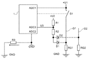
図1に模式的に示したグローシステムは、図1に抵抗RG1およびRG2として示されている複数のグロープラグを包含する。もちろん前記グローシステムにそれぞれ必要に応じてその他のグロープラグを付加することもできる。各グロープラグRG1、RG2は供給回線G1もしくはG2を介して供給電圧U1に印加できる電位接続部を有する。各供給回線G1、G2の中にスイッチS1が配置されており、その結果、グロープラグRG1、RG2の通電がパルス幅変調による出力制御のために必要に応じて遮断することができる。スイッチS1、好ましくはパワートランジスタは出力制御のために制御部1によって操作される。
The glow system schematically shown in FIG. 1 includes a plurality of glow plugs shown in FIG. 1 as resistors RG1 and RG2. Of course, other glow plugs may be added to the glow system as necessary. Each glow plug RG1, RG2 has a potential connection that can be applied to the supply voltage U1 via the supply line G1 or G2. A switch S1 is arranged in each of the supply lines G1 and G2. As a result, energization of the glow plugs RG1 and RG2 can be cut off as necessary for output control by pulse width modulation. The switch S1, preferably the power transistor, is operated by the
制御部1はアナログ・ディジタル変換器を備えるマイクロプロセッサを包含する。出力制御は制御部1によってグロープラグRG1への所望の電力を供給するために好適な時間間隔のパルス幅を発生するスイッチS1が開放もしくは閉鎖されるパルス幅変調方法によって実施される。パルス幅の持続時間は制御部1によって所望の電力を供給するために供給電圧U1の強さに応じて決定される。たとえば約11ボルトの供給電圧U1は自動車の車載電気系統から供給される。
The
供給電圧U1の測定のために制御部1は該制御部の内蔵型アナログ・ディジタル変換器の測定入力部ADC1を有する。前記測定入力部ADC1に図1に従ってグロープラグRG1、RG2の電位接続部と同様に供給電圧U1が供給される。供給電圧U1は制御部1によって制御部1のアース入力部ADC2に印加される基準電位GND’と相対的に測定される。基準電位GND’は、たとえば自動車技術において電子部品の接続によく使用される破損したプラグコネクタによって生じ得る粗悪なコンタクトのためにグロープラグRG1、RG2のアース接続部に印加されるアース電位GNDから変位し得る。そのため図1に基準電位GND’とアース電位GNDとの間にアース電位GNDへの制御部1のアース入力部ADC2の接続不良に基づく抵抗R3が示されている。
For the measurement of the supply voltage U1, the
妨害抵抗R3は基準電位GND’がアース電位GNDから変位し、その結果供給電圧U1用の制御部1によって検出される電圧値がグロープラグRG1、RG2で降下する電圧値から変位することを生ぜしめる。
The disturbing resistor R3 causes the reference potential GND ′ to be displaced from the ground potential GND, and as a result, the voltage value detected by the
アース電位GNDからの生じ得る基準電位GND’の変位を検出できるようにするため、制御部1は第1の固定抵抗R1を介して定試験電圧U2を供給する試験電圧源に接続された試験入力部ADC3を有する。試験入力部ADC3は、さらに第2の固定抵抗R2を介してグロープラグRG1、RG2の電位接続部へ接続されている。図示した実施例において固定抵抗R2はそれぞれ1つのグロープラグRG1、RG2と並列に接続されている。
In order to be able to detect a possible displacement of the reference potential GND ′ from the ground potential GND, the
アース入力部ADC2に印加される基準電位GND’がグロープラグRG1、RG2のアース接続部へ印加されるアース電位GNDから変位するかどうかを検査するために、供給電圧U1はグロープラグRG1、RG2の電位接続部から接続を外される。そのためにスイッチS1が制御部1によって開放される。
In order to check whether the reference potential GND ′ applied to the ground input ADC2 is displaced from the ground potential GND applied to the ground connection of the glow plugs RG1, RG2, the supply voltage U1 is applied to the glow plugs RG1, RG2. Disconnect from the potential connection. For this purpose, the switch S1 is opened by the
規定された抵抗R1およびR2が分圧器回路を構成し、その結果、試験入力部ADC3に、電圧値が第1の近似で試験電圧U2の値と固定抵抗R1およびR2にのみ依存するので、アース電位GNDに対する該電圧値が非常に正確に知られている電圧U3が印加される。前記電圧U3の正確な値は原理的にもちろんその他の要因、たとえばグロープラグRG1、RG2の電気抵抗によっても影響される。グロープラグの電気抵抗はリード線を含め室温で典型的に約0.5オームのみになるので、前記の影響は通常無視することができ、必要であればより正確な計算によって考慮に入れることができる。固定抵抗R1およびR2は典型的に数百オームの値、試験電圧U2は、好ましくは5ボルトの値を有する。試験電圧源は、好ましくは制御部が必要とする動作電圧も供給する。そのため試験電圧源として制御部1のマイクロプロセッサにいずれにせよ必要になる電源を使用してもよい。
The defined resistors R1 and R2 constitute a voltage divider circuit, so that the voltage value of the test input ADC3 depends only on the value of the test voltage U2 and the fixed resistors R1 and R2 in the first approximation, A voltage U3 is applied whose voltage value with respect to the potential GND is known very accurately. The exact value of the voltage U3 is in principle also influenced by other factors, for example the electrical resistance of the glow plugs RG1, RG2. Since the electrical resistance of the glow plug is typically only about 0.5 ohms at room temperature, including the lead, this effect is usually negligible and can be taken into account by more accurate calculations if necessary. it can. Fixed resistors R1 and R2 typically have a value of several hundred ohms, and test voltage U2 preferably has a value of 5 volts. The test voltage source preferably also supplies the operating voltage required by the controller. Therefore, any power source necessary for the microprocessor of the
第1の抵抗R1および第2の抵抗R2は、好ましくはグロープラグRG1、RG2の抵抗よりもそれぞれ少なくとも50倍、好ましくは少なくとも200倍、特に少なくとも1000倍大きい。この措置は、グロープラグRG1、RG2の電気抵抗が良好な近似で試験入力部ADC3に印加される電位U3に影響を及ぼさない長所を有する。 The first resistance R1 and the second resistance R2 are preferably at least 50 times, preferably at least 200 times, in particular at least 1000 times greater than the resistances of the glow plugs RG1, RG2, respectively. This measure has the advantage that the electrical resistance of the glow plugs RG1, RG2 is a good approximation and does not affect the potential U3 applied to the test input ADC3.
試験入力部ADC3に印加される電位U3の値が基準電位GND’と相対的に上述のように第1の近似で固定抵抗R1、R2および試験電圧U2の値にのみ依存する目標値から変位することを制御部1が検出するとき、これは基準電位GND’もアース電位GNDから変位することを意味する。場合により検出された変位は制御部1によってアース入力部に印加される基準電位GND’と相対的に測定された供給電圧U1の測定値の補正に使用される。この方法によって、出力制御のためにより大きい精度でグロープラグRG1、RG2に所望の電力を供給することができる。
As described above, the value of the potential U3 applied to the test input unit ADC3 is displaced from the target value depending only on the values of the fixed resistors R1, R2 and the test voltage U2 in the first approximation as described above. When the
試験電圧U2は、好ましくはたとえば11ボルトになる供給電圧U1よりも小さい。そのため第2の固定抵抗R2とグロープラグRG1、RG2の電位接続部との間に図示した実施例においてダイオードD1もしくはD2が配置されている。ダイオードD1、D2は、供給電圧U1が制御部1の試験入力部ADC3に印加される電位U3の値に影響を及ぼすことを阻止する。
The test voltage U2 is preferably smaller than the supply voltage U1, for example 11 volts. Therefore, the diode D1 or D2 is arranged in the illustrated embodiment between the second fixed resistor R2 and the potential connection portion of the glow plugs RG1 and RG2. The diodes D1 and D2 prevent the supply voltage U1 from affecting the value of the potential U3 applied to the test input ADC3 of the
RG1 グロープラグ
RG2 グロープラグ
G1 供給回線
G2 供給回線
U1 供給電圧
S1 スイッチ
1 制御部
ADC1 測定入力部
GND’ 基準電位
ADC2 アース入力部
GND アース電位
R3 妨害抵抗
R1 固定抵抗
U2 試験電圧
ADC3 試験入力部
R2 固定抵抗
U3 電圧
D1 ダイオード
D2 ダイオード
RG1 Glow plug RG2 Glow plug G1 Supply line G2 Supply line U1 Supply
Claims (10)
制御部(1)が運転中に第1の抵抗(R1)を介して試験電圧源へ、かつ第2の抵抗(R2)を介してグロープラグ(RG1、RG2)の電位接続部へ接続された試験入力部(ADC3)を有し、制御部(1)が運転中に試験入力部(ADC3)の電位とアース入力部(ADC2)の電位(GND’)との間の電位差を検出し、目標値からの電位差の変位を検出し、かつ該変位が零ではない場合、前記変位がアース入力部(ADC2)に印加される基準電位(GND’)と相対的に測定される供給電圧(U1)の測定値の補正のために使用され、かつ出力制御のために供給電圧(U1)の補正値を起点として導き出されることを特徴とするグローシステム。 A glow plug (RG1, RG2) having a potential connection for applying the supply voltage (U1) and a ground connection for connecting to the ground potential (GND), and a glow plug (RG1, RG2) during operation And a control unit (1) for controlling the power supplied to the sensor, and detects a measured value of the supply voltage U1 relative to a reference potential (GND ′) applied to the ground input unit (ADC2) during operation. A glow system for a diesel engine of an automobile in which the control unit (1) includes a measurement input unit (ADC1) and a ground input unit (ADC2),
The control unit (1) is connected to the test voltage source via the first resistor (R1) and to the potential connection of the glow plugs (RG1, RG2) via the second resistor (R2) during operation. It has a test input unit (ADC3), and the control unit (1) detects the potential difference between the potential of the test input unit (ADC3) and the potential of the ground input unit (ADC2) (GND ′) during operation. When the displacement of the potential difference from the value is detected and the displacement is not zero, the displacement is measured relative to the reference potential (GND ′) applied to the ground input part (ADC2) (U1) A glow system characterized in that it is used for correction of the measured value of the power supply and is derived from the correction value of the supply voltage (U1) as a starting point for output control.
制御部(1)が第1の抵抗(R1)を介して試験電圧源へ接続されており、かつ第2の抵抗(R2)を介して規定どおりに消費体(RG1、RG2)の電位接続部へ接続される試験入力部(ADC3)を有し、運転中に試験入力部(ADC3)の電位とアース入力部(ADC2)の電位との間の電位差を検出し、目標値からの電位差の変位を検出し、かつ該変位が零ではない場合、前記変位がアース入力部(ADC2)に印加される電位と相対的に測定される供給電圧(U1)の測定値の補正のために使用され、かつ出力制御のために供給電圧(U1)の補正値を起点として導き出されることを特徴とする制御部。 In the control unit (1) for controlling the output of the power consumer for the glow system, the supply voltage of the consumer (relative to the reference potential (GND ′) applied to the ground input unit (ADC2) during operation). The control unit (1) has a measurement input unit (ADC1) and a ground input unit (ADC2) to detect the measurement value of U1),
The control part (1) is connected to the test voltage source via the first resistor (R1), and the potential connection part of the consumer (RG1, RG2) as specified via the second resistor (R2) A test input unit (ADC3) connected to the terminal, detects a potential difference between the potential of the test input unit (ADC3) and the potential of the ground input unit (ADC2) during operation, and shifts the potential difference from the target value , And the displacement is not zero, the displacement is used to correct the measured value of the supply voltage (U1) measured relative to the potential applied to the ground input (ADC2); And a control unit derived from a correction value of the supply voltage (U1) as a starting point for output control.
前記供給電圧(U1)が電圧測定装置のアース入力部(ACD2)に印加される基準電位(GND’)と相対的に測定され、アース電位(GND)に一端が接続された前記グロープラグ(RG1、RG2)の他端側と測定用の電圧を供給する試験電圧源との間に直列に接続された、第1の抵抗(R1)と第2の抵抗(R2)との接続点の電位が、前記基準電位(GND’)に対して測定され、測定された前記接続点の電位と所定の目標値との偏差が特定されることによって、前記基準電位(GND’)がグロープラグ(RG1、RG2)に印加される前記アース電位(GND)から変位しているかどうかが検査されるとともに、前記アース電位からの変位の値が特定され、前記グロープラグ(RG1、RG2)へ所望の出力を取り込むために印加される供給電圧パルスの持続時間が、前記基準電位(GND’)と相対的に測定された前記供給電圧(U1)の値と、前記アース電位(GND)からの前記基準電位(GND’)の前記変位の値とから計算されることを特徴とする方法。 An output control method of glow plugs (RG1, RG2) by pulse width modulation of a supply voltage (U1),
The glow plug (RG1) having one end connected to the ground potential (GND), the supply voltage (U1) is measured relative to a reference potential (GND ') applied to the ground input (ACD2) of the voltage measuring device. , RG2) is connected in series between the other end of RG2) and a test voltage source for supplying a measurement voltage, and the potential at the connection point between the first resistor (R1) and the second resistor (R2) is The reference potential (GND ′) is measured with respect to the reference potential (GND ′), and a deviation between the measured potential of the connection point and a predetermined target value is specified, whereby the reference potential (GND ′) is changed to a glow plug (RG1, with whether the displacement is examined from the ground potential to be applied (GND) in RG2), the value of the displacement from the earth potential is specific, the desired output to the glow plug (RG1, RG2) Applied to capture The duration of the supply voltage pulses to the said reference potential (GND ') and the value of the measured relative the supply voltage (U1), the reference potential from the ground potential (GND) (GND') A method characterized in that it is calculated from a displacement value.
Applications Claiming Priority (2)
| Application Number | Priority Date | Filing Date | Title |
|---|---|---|---|
| DE102007029022.7 | 2007-06-23 | ||
| DE102007029022A DE102007029022B4 (en) | 2007-06-23 | 2007-06-23 | Annealing system, control device and method for controlling the power of a glow plug |
Publications (2)
| Publication Number | Publication Date |
|---|---|
| JP2009002347A JP2009002347A (en) | 2009-01-08 |
| JP5153473B2 true JP5153473B2 (en) | 2013-02-27 |
Family
ID=39769422
Family Applications (1)
| Application Number | Title | Priority Date | Filing Date |
|---|---|---|---|
| JP2008163586A Expired - Fee Related JP5153473B2 (en) | 2007-06-23 | 2008-06-23 | Glow system, control unit, and glow plug output control method |
Country Status (5)
| Country | Link |
|---|---|
| US (1) | US8017888B2 (en) |
| EP (1) | EP2006534B1 (en) |
| JP (1) | JP5153473B2 (en) |
| KR (1) | KR101501044B1 (en) |
| DE (1) | DE102007029022B4 (en) |
Families Citing this family (4)
| Publication number | Priority date | Publication date | Assignee | Title |
|---|---|---|---|---|
| DE102007029022B4 (en) * | 2007-06-23 | 2009-05-14 | Beru Ag | Annealing system, control device and method for controlling the power of a glow plug |
| DE102008054510A1 (en) * | 2008-12-11 | 2010-06-17 | Robert Bosch Gmbh | Control unit for a plurality of glow plugs and method thereof |
| JP2014025447A (en) * | 2012-07-30 | 2014-02-06 | Ngk Spark Plug Co Ltd | Energization control device for glow plug, and energization control method of glow plug |
| DE102015222722A1 (en) * | 2015-11-18 | 2017-05-18 | Robert Bosch Gmbh | A method of operating and apparatus for operating a number of n glow plugs |
Family Cites Families (15)
| Publication number | Priority date | Publication date | Assignee | Title |
|---|---|---|---|---|
| CA1132661A (en) * | 1979-02-14 | 1982-09-28 | Rodney Hayden | Resistive device sensor |
| EP0315934B1 (en) * | 1987-11-09 | 1994-01-19 | Siemens Aktiengesellschaft | Regulation method for the glow plug temperature in a diesel engine, and circuit therefor |
| US4939347A (en) * | 1987-12-17 | 1990-07-03 | Jidosha Kiki Co., Ltd. | Energization control apparatus for glow plug |
| JP2794295B2 (en) * | 1988-07-11 | 1998-09-03 | ヤマハ発動機株式会社 | Gas engine generator |
| DE4328719A1 (en) * | 1993-08-26 | 1995-03-02 | Bosch Gmbh Robert | Method for monitoring at least one electrical consumer |
| DE19708430A1 (en) * | 1996-05-21 | 1997-11-27 | Stribel Gmbh | Method and device for controlling the glow process of a glow plug of a diesel engine |
| ES2237782T3 (en) * | 1996-05-21 | 2005-08-01 | Alcoa Fujikura Gesellschaft Mit Beschrankter Haftung | PROCEDURE AND DEVICE FOR THE CONTROL OF THE INCANDESCENCE PROCESS OF A DIESEL ENGINE SPARK PLUG. |
| DE29620634U1 (en) | 1996-11-27 | 1997-02-06 | Hella Kg Hueck & Co, 59557 Lippstadt | Control device in a motor vehicle |
| JP4256517B2 (en) * | 1999-02-25 | 2009-04-22 | 日本特殊陶業株式会社 | Glow plug control device and glow plug control method |
| JP3616320B2 (en) * | 2000-09-21 | 2005-02-02 | 本田技研工業株式会社 | Ignition timing control device for internal combustion engine |
| JP3810744B2 (en) * | 2003-01-29 | 2006-08-16 | 日本特殊陶業株式会社 | Glow plug energization control device and glow plug energization control method |
| JP4391774B2 (en) * | 2003-07-17 | 2009-12-24 | トヨタ自動車株式会社 | Control device for internal combustion engine and control method for internal combustion engine |
| JP4422693B2 (en) * | 2006-03-20 | 2010-02-24 | トヨタ自動車株式会社 | Ignition timing control device for internal combustion engine |
| EP1933025A1 (en) | 2006-12-16 | 2008-06-18 | GM Global Technology Operations, Inc. | A system and method for controlling resistive loads with ground return connected to the engine ground |
| DE102007029022B4 (en) * | 2007-06-23 | 2009-05-14 | Beru Ag | Annealing system, control device and method for controlling the power of a glow plug |
-
2007
- 2007-06-23 DE DE102007029022A patent/DE102007029022B4/en not_active Expired - Fee Related
-
2008
- 2008-06-18 EP EP08011014A patent/EP2006534B1/en not_active Not-in-force
- 2008-06-20 US US12/214,657 patent/US8017888B2/en active Active
- 2008-06-23 JP JP2008163586A patent/JP5153473B2/en not_active Expired - Fee Related
- 2008-06-23 KR KR1020080058838A patent/KR101501044B1/en not_active Expired - Fee Related
Also Published As
| Publication number | Publication date |
|---|---|
| US20080314889A1 (en) | 2008-12-25 |
| KR20080113161A (en) | 2008-12-29 |
| US8017888B2 (en) | 2011-09-13 |
| EP2006534A3 (en) | 2010-03-24 |
| DE102007029022A1 (en) | 2008-12-24 |
| EP2006534A2 (en) | 2008-12-24 |
| DE102007029022B4 (en) | 2009-05-14 |
| KR101501044B1 (en) | 2015-03-10 |
| JP2009002347A (en) | 2009-01-08 |
| EP2006534B1 (en) | 2013-01-02 |
Similar Documents
| Publication | Publication Date | Title |
|---|---|---|
| US9170229B2 (en) | Method for diagnosing an electrical contact connection of an exhaust gas sensor | |
| US20110040457A1 (en) | Method and device for learning the neutral position of the accelerator pedal of a motor vehicle | |
| JP5153473B2 (en) | Glow system, control unit, and glow plug output control method | |
| JP6267866B2 (en) | Insulation state detector | |
| CN102844207B (en) | Circuit arrangement structure for electric seat heating device | |
| KR101717065B1 (en) | Lambda sensor preheating control method and lambda sensor driving control device | |
| CN113950867B (en) | Device for determining the temperature of a resistance heating device | |
| JP2017037835A (en) | Method to ensure the operation of the heating device | |
| KR20160073321A (en) | Method and device for diagnosis of an additional heating functionality of an air mass flow sensor | |
| US8225646B2 (en) | Throttle body sweep diagnostic system and method | |
| KR102209843B1 (en) | Method for detecting a Glow Plug Replacement | |
| EP2940288A1 (en) | Glow plug diagnosis method and device for controlling driving of vehicle glow plug | |
| US11209490B2 (en) | Method for operating a battery sensor, and battery sensor | |
| US7813885B2 (en) | Method and apparatus for measurement of AC voltages in an HVAC system | |
| JP2001193546A (en) | Method and apparatus for controlling a regulating element | |
| JPH11327666A (en) | Method of monitoring at least one current regulation stage and device for monitoring at least one current regulation stage | |
| JP2017129054A (en) | Thermocouple abnormality detection apparatus and thermocouple abnormality detection method | |
| US9341156B2 (en) | Glow plug, new glow plug determination method, and glow plug driving control device | |
| CN111147001B (en) | Power supply circuit and motor control device | |
| KR101766981B1 (en) | Intergrated sensor for detecting rotating object | |
| KR101816264B1 (en) | Apparatus and method for testing engine controller battery voltage | |
| KR101774664B1 (en) | Apparatus and method for detecting temperature | |
| KR102201455B1 (en) | Method for operating a sensor evaluation unit and sensor evaluation unit | |
| JP4173696B2 (en) | LOAD CONTROL METHOD AND CONTROL DEVICE | |
| KR20160098271A (en) | Method for controlling an output stage of an electrical consumer in a motor vehicle |
Legal Events
| Date | Code | Title | Description |
|---|---|---|---|
| RD02 | Notification of acceptance of power of attorney |
Free format text: JAPANESE INTERMEDIATE CODE: A7422 Effective date: 20100714 |
|
| A621 | Written request for application examination |
Free format text: JAPANESE INTERMEDIATE CODE: A621 Effective date: 20110506 |
|
| A131 | Notification of reasons for refusal |
Free format text: JAPANESE INTERMEDIATE CODE: A131 Effective date: 20120424 |
|
| A521 | Request for written amendment filed |
Free format text: JAPANESE INTERMEDIATE CODE: A523 Effective date: 20120702 |
|
| TRDD | Decision of grant or rejection written | ||
| A01 | Written decision to grant a patent or to grant a registration (utility model) |
Free format text: JAPANESE INTERMEDIATE CODE: A01 Effective date: 20121113 |
|
| A61 | First payment of annual fees (during grant procedure) |
Free format text: JAPANESE INTERMEDIATE CODE: A61 Effective date: 20121204 |
|
| FPAY | Renewal fee payment (event date is renewal date of database) |
Free format text: PAYMENT UNTIL: 20151214 Year of fee payment: 3 |
|
| R150 | Certificate of patent or registration of utility model |
Free format text: JAPANESE INTERMEDIATE CODE: R150 |
|
| R250 | Receipt of annual fees |
Free format text: JAPANESE INTERMEDIATE CODE: R250 |
|
| LAPS | Cancellation because of no payment of annual fees |