JP5155155B2 - Brake system for electric drive dump truck - Google Patents
Brake system for electric drive dump truck Download PDFInfo
- Publication number
- JP5155155B2 JP5155155B2 JP2008513851A JP2008513851A JP5155155B2 JP 5155155 B2 JP5155155 B2 JP 5155155B2 JP 2008513851 A JP2008513851 A JP 2008513851A JP 2008513851 A JP2008513851 A JP 2008513851A JP 5155155 B2 JP5155155 B2 JP 5155155B2
- Authority
- JP
- Japan
- Prior art keywords
- brake
- hydraulic
- dump truck
- brake pedal
- depression
- Prior art date
- Legal status (The legal status is an assumption and is not a legal conclusion. Google has not performed a legal analysis and makes no representation as to the accuracy of the status listed.)
- Active
Links
Images




Classifications
-
- B—PERFORMING OPERATIONS; TRANSPORTING
- B60—VEHICLES IN GENERAL
- B60W—CONJOINT CONTROL OF VEHICLE SUB-UNITS OF DIFFERENT TYPE OR DIFFERENT FUNCTION; CONTROL SYSTEMS SPECIALLY ADAPTED FOR HYBRID VEHICLES; ROAD VEHICLE DRIVE CONTROL SYSTEMS FOR PURPOSES NOT RELATED TO THE CONTROL OF A PARTICULAR SUB-UNIT
- B60W10/00—Conjoint control of vehicle sub-units of different type or different function
- B60W10/04—Conjoint control of vehicle sub-units of different type or different function including control of propulsion units
- B60W10/08—Conjoint control of vehicle sub-units of different type or different function including control of propulsion units including control of electric propulsion units, e.g. motors or generators
-
- B—PERFORMING OPERATIONS; TRANSPORTING
- B60—VEHICLES IN GENERAL
- B60K—ARRANGEMENT OR MOUNTING OF PROPULSION UNITS OR OF TRANSMISSIONS IN VEHICLES; ARRANGEMENT OR MOUNTING OF PLURAL DIVERSE PRIME-MOVERS IN VEHICLES; AUXILIARY DRIVES FOR VEHICLES; INSTRUMENTATION OR DASHBOARDS FOR VEHICLES; ARRANGEMENTS IN CONNECTION WITH COOLING, AIR INTAKE, GAS EXHAUST OR FUEL SUPPLY OF PROPULSION UNITS IN VEHICLES
- B60K6/00—Arrangement or mounting of plural diverse prime-movers for mutual or common propulsion, e.g. hybrid propulsion systems comprising electric motors and internal combustion engines
- B60K6/20—Arrangement or mounting of plural diverse prime-movers for mutual or common propulsion, e.g. hybrid propulsion systems comprising electric motors and internal combustion engines the prime-movers consisting of electric motors and internal combustion engines, e.g. HEVs
- B60K6/42—Arrangement or mounting of plural diverse prime-movers for mutual or common propulsion, e.g. hybrid propulsion systems comprising electric motors and internal combustion engines the prime-movers consisting of electric motors and internal combustion engines, e.g. HEVs characterised by the architecture of the hybrid electric vehicle
- B60K6/46—Series type
-
- B—PERFORMING OPERATIONS; TRANSPORTING
- B60—VEHICLES IN GENERAL
- B60L—PROPULSION OF ELECTRICALLY-PROPELLED VEHICLES; SUPPLYING ELECTRIC POWER FOR AUXILIARY EQUIPMENT OF ELECTRICALLY-PROPELLED VEHICLES; ELECTRODYNAMIC BRAKE SYSTEMS FOR VEHICLES IN GENERAL; MAGNETIC SUSPENSION OR LEVITATION FOR VEHICLES; MONITORING OPERATING VARIABLES OF ELECTRICALLY-PROPELLED VEHICLES; ELECTRIC SAFETY DEVICES FOR ELECTRICALLY-PROPELLED VEHICLES
- B60L3/00—Electric devices on electrically-propelled vehicles for safety purposes; Monitoring operating variables, e.g. speed, deceleration or energy consumption
- B60L3/0023—Detecting, eliminating, remedying or compensating for drive train abnormalities, e.g. failures within the drive train
- B60L3/0061—Detecting, eliminating, remedying or compensating for drive train abnormalities, e.g. failures within the drive train relating to electrical machines
-
- B—PERFORMING OPERATIONS; TRANSPORTING
- B60—VEHICLES IN GENERAL
- B60L—PROPULSION OF ELECTRICALLY-PROPELLED VEHICLES; SUPPLYING ELECTRIC POWER FOR AUXILIARY EQUIPMENT OF ELECTRICALLY-PROPELLED VEHICLES; ELECTRODYNAMIC BRAKE SYSTEMS FOR VEHICLES IN GENERAL; MAGNETIC SUSPENSION OR LEVITATION FOR VEHICLES; MONITORING OPERATING VARIABLES OF ELECTRICALLY-PROPELLED VEHICLES; ELECTRIC SAFETY DEVICES FOR ELECTRICALLY-PROPELLED VEHICLES
- B60L3/00—Electric devices on electrically-propelled vehicles for safety purposes; Monitoring operating variables, e.g. speed, deceleration or energy consumption
- B60L3/12—Recording operating variables ; Monitoring of operating variables
-
- B—PERFORMING OPERATIONS; TRANSPORTING
- B60—VEHICLES IN GENERAL
- B60L—PROPULSION OF ELECTRICALLY-PROPELLED VEHICLES; SUPPLYING ELECTRIC POWER FOR AUXILIARY EQUIPMENT OF ELECTRICALLY-PROPELLED VEHICLES; ELECTRODYNAMIC BRAKE SYSTEMS FOR VEHICLES IN GENERAL; MAGNETIC SUSPENSION OR LEVITATION FOR VEHICLES; MONITORING OPERATING VARIABLES OF ELECTRICALLY-PROPELLED VEHICLES; ELECTRIC SAFETY DEVICES FOR ELECTRICALLY-PROPELLED VEHICLES
- B60L50/00—Electric propulsion with power supplied within the vehicle
- B60L50/10—Electric propulsion with power supplied within the vehicle using propulsion power supplied by engine-driven generators, e.g. generators driven by combustion engines
- B60L50/13—Electric propulsion with power supplied within the vehicle using propulsion power supplied by engine-driven generators, e.g. generators driven by combustion engines using AC generators and AC motors
-
- B—PERFORMING OPERATIONS; TRANSPORTING
- B60—VEHICLES IN GENERAL
- B60L—PROPULSION OF ELECTRICALLY-PROPELLED VEHICLES; SUPPLYING ELECTRIC POWER FOR AUXILIARY EQUIPMENT OF ELECTRICALLY-PROPELLED VEHICLES; ELECTRODYNAMIC BRAKE SYSTEMS FOR VEHICLES IN GENERAL; MAGNETIC SUSPENSION OR LEVITATION FOR VEHICLES; MONITORING OPERATING VARIABLES OF ELECTRICALLY-PROPELLED VEHICLES; ELECTRIC SAFETY DEVICES FOR ELECTRICALLY-PROPELLED VEHICLES
- B60L7/00—Electrodynamic brake systems for vehicles in general
- B60L7/02—Dynamic electric resistor braking
- B60L7/06—Dynamic electric resistor braking for vehicles propelled by AC motors
-
- B—PERFORMING OPERATIONS; TRANSPORTING
- B60—VEHICLES IN GENERAL
- B60L—PROPULSION OF ELECTRICALLY-PROPELLED VEHICLES; SUPPLYING ELECTRIC POWER FOR AUXILIARY EQUIPMENT OF ELECTRICALLY-PROPELLED VEHICLES; ELECTRODYNAMIC BRAKE SYSTEMS FOR VEHICLES IN GENERAL; MAGNETIC SUSPENSION OR LEVITATION FOR VEHICLES; MONITORING OPERATING VARIABLES OF ELECTRICALLY-PROPELLED VEHICLES; ELECTRIC SAFETY DEVICES FOR ELECTRICALLY-PROPELLED VEHICLES
- B60L7/00—Electrodynamic brake systems for vehicles in general
- B60L7/10—Dynamic electric regenerative braking
- B60L7/14—Dynamic electric regenerative braking for vehicles propelled by AC motors
-
- B—PERFORMING OPERATIONS; TRANSPORTING
- B60—VEHICLES IN GENERAL
- B60L—PROPULSION OF ELECTRICALLY-PROPELLED VEHICLES; SUPPLYING ELECTRIC POWER FOR AUXILIARY EQUIPMENT OF ELECTRICALLY-PROPELLED VEHICLES; ELECTRODYNAMIC BRAKE SYSTEMS FOR VEHICLES IN GENERAL; MAGNETIC SUSPENSION OR LEVITATION FOR VEHICLES; MONITORING OPERATING VARIABLES OF ELECTRICALLY-PROPELLED VEHICLES; ELECTRIC SAFETY DEVICES FOR ELECTRICALLY-PROPELLED VEHICLES
- B60L7/00—Electrodynamic brake systems for vehicles in general
- B60L7/24—Electrodynamic brake systems for vehicles in general with additional mechanical or electromagnetic braking
- B60L7/26—Controlling the braking effect
-
- B—PERFORMING OPERATIONS; TRANSPORTING
- B60—VEHICLES IN GENERAL
- B60T—VEHICLE BRAKE CONTROL SYSTEMS OR PARTS THEREOF; BRAKE CONTROL SYSTEMS OR PARTS THEREOF, IN GENERAL; ARRANGEMENT OF BRAKING ELEMENTS ON VEHICLES IN GENERAL; PORTABLE DEVICES FOR PREVENTING UNWANTED MOVEMENT OF VEHICLES; VEHICLE MODIFICATIONS TO FACILITATE COOLING OF BRAKES
- B60T13/00—Transmitting braking action from initiating means to ultimate brake actuator with power assistance or drive; Brake systems incorporating such transmitting means, e.g. air-pressure brake systems
- B60T13/10—Transmitting braking action from initiating means to ultimate brake actuator with power assistance or drive; Brake systems incorporating such transmitting means, e.g. air-pressure brake systems with fluid assistance, drive, or release
- B60T13/58—Combined or convertible systems
- B60T13/585—Combined or convertible systems comprising friction brakes and retarders
- B60T13/586—Combined or convertible systems comprising friction brakes and retarders the retarders being of the electric type
-
- B—PERFORMING OPERATIONS; TRANSPORTING
- B60—VEHICLES IN GENERAL
- B60T—VEHICLE BRAKE CONTROL SYSTEMS OR PARTS THEREOF; BRAKE CONTROL SYSTEMS OR PARTS THEREOF, IN GENERAL; ARRANGEMENT OF BRAKING ELEMENTS ON VEHICLES IN GENERAL; PORTABLE DEVICES FOR PREVENTING UNWANTED MOVEMENT OF VEHICLES; VEHICLE MODIFICATIONS TO FACILITATE COOLING OF BRAKES
- B60T8/00—Arrangements for adjusting wheel-braking force to meet varying vehicular or ground-surface conditions, e.g. limiting or varying distribution of braking force
-
- B—PERFORMING OPERATIONS; TRANSPORTING
- B60—VEHICLES IN GENERAL
- B60W—CONJOINT CONTROL OF VEHICLE SUB-UNITS OF DIFFERENT TYPE OR DIFFERENT FUNCTION; CONTROL SYSTEMS SPECIALLY ADAPTED FOR HYBRID VEHICLES; ROAD VEHICLE DRIVE CONTROL SYSTEMS FOR PURPOSES NOT RELATED TO THE CONTROL OF A PARTICULAR SUB-UNIT
- B60W10/00—Conjoint control of vehicle sub-units of different type or different function
- B60W10/18—Conjoint control of vehicle sub-units of different type or different function including control of braking systems
- B60W10/184—Conjoint control of vehicle sub-units of different type or different function including control of braking systems with wheel brakes
-
- B—PERFORMING OPERATIONS; TRANSPORTING
- B60—VEHICLES IN GENERAL
- B60W—CONJOINT CONTROL OF VEHICLE SUB-UNITS OF DIFFERENT TYPE OR DIFFERENT FUNCTION; CONTROL SYSTEMS SPECIALLY ADAPTED FOR HYBRID VEHICLES; ROAD VEHICLE DRIVE CONTROL SYSTEMS FOR PURPOSES NOT RELATED TO THE CONTROL OF A PARTICULAR SUB-UNIT
- B60W30/00—Purposes of road vehicle drive control systems not related to the control of a particular sub-unit, e.g. of systems using conjoint control of vehicle sub-units
- B60W30/18—Propelling the vehicle
- B60W30/18009—Propelling the vehicle related to particular drive situations
- B60W30/18109—Braking
-
- B—PERFORMING OPERATIONS; TRANSPORTING
- B60—VEHICLES IN GENERAL
- B60L—PROPULSION OF ELECTRICALLY-PROPELLED VEHICLES; SUPPLYING ELECTRIC POWER FOR AUXILIARY EQUIPMENT OF ELECTRICALLY-PROPELLED VEHICLES; ELECTRODYNAMIC BRAKE SYSTEMS FOR VEHICLES IN GENERAL; MAGNETIC SUSPENSION OR LEVITATION FOR VEHICLES; MONITORING OPERATING VARIABLES OF ELECTRICALLY-PROPELLED VEHICLES; ELECTRIC SAFETY DEVICES FOR ELECTRICALLY-PROPELLED VEHICLES
- B60L2200/00—Type of vehicles
- B60L2200/36—Vehicles designed to transport cargo, e.g. trucks
-
- B—PERFORMING OPERATIONS; TRANSPORTING
- B60—VEHICLES IN GENERAL
- B60L—PROPULSION OF ELECTRICALLY-PROPELLED VEHICLES; SUPPLYING ELECTRIC POWER FOR AUXILIARY EQUIPMENT OF ELECTRICALLY-PROPELLED VEHICLES; ELECTRODYNAMIC BRAKE SYSTEMS FOR VEHICLES IN GENERAL; MAGNETIC SUSPENSION OR LEVITATION FOR VEHICLES; MONITORING OPERATING VARIABLES OF ELECTRICALLY-PROPELLED VEHICLES; ELECTRIC SAFETY DEVICES FOR ELECTRICALLY-PROPELLED VEHICLES
- B60L2210/00—Converter types
- B60L2210/30—AC to DC converters
-
- B—PERFORMING OPERATIONS; TRANSPORTING
- B60—VEHICLES IN GENERAL
- B60L—PROPULSION OF ELECTRICALLY-PROPELLED VEHICLES; SUPPLYING ELECTRIC POWER FOR AUXILIARY EQUIPMENT OF ELECTRICALLY-PROPELLED VEHICLES; ELECTRODYNAMIC BRAKE SYSTEMS FOR VEHICLES IN GENERAL; MAGNETIC SUSPENSION OR LEVITATION FOR VEHICLES; MONITORING OPERATING VARIABLES OF ELECTRICALLY-PROPELLED VEHICLES; ELECTRIC SAFETY DEVICES FOR ELECTRICALLY-PROPELLED VEHICLES
- B60L2210/00—Converter types
- B60L2210/40—DC to AC converters
-
- B—PERFORMING OPERATIONS; TRANSPORTING
- B60—VEHICLES IN GENERAL
- B60L—PROPULSION OF ELECTRICALLY-PROPELLED VEHICLES; SUPPLYING ELECTRIC POWER FOR AUXILIARY EQUIPMENT OF ELECTRICALLY-PROPELLED VEHICLES; ELECTRODYNAMIC BRAKE SYSTEMS FOR VEHICLES IN GENERAL; MAGNETIC SUSPENSION OR LEVITATION FOR VEHICLES; MONITORING OPERATING VARIABLES OF ELECTRICALLY-PROPELLED VEHICLES; ELECTRIC SAFETY DEVICES FOR ELECTRICALLY-PROPELLED VEHICLES
- B60L2220/00—Electrical machine types; Structures or applications thereof
- B60L2220/40—Electrical machine applications
- B60L2220/46—Wheel motors, i.e. motor connected to only one wheel
-
- B—PERFORMING OPERATIONS; TRANSPORTING
- B60—VEHICLES IN GENERAL
- B60L—PROPULSION OF ELECTRICALLY-PROPELLED VEHICLES; SUPPLYING ELECTRIC POWER FOR AUXILIARY EQUIPMENT OF ELECTRICALLY-PROPELLED VEHICLES; ELECTRODYNAMIC BRAKE SYSTEMS FOR VEHICLES IN GENERAL; MAGNETIC SUSPENSION OR LEVITATION FOR VEHICLES; MONITORING OPERATING VARIABLES OF ELECTRICALLY-PROPELLED VEHICLES; ELECTRIC SAFETY DEVICES FOR ELECTRICALLY-PROPELLED VEHICLES
- B60L2240/00—Control parameters of input or output; Target parameters
- B60L2240/10—Vehicle control parameters
- B60L2240/12—Speed
-
- B—PERFORMING OPERATIONS; TRANSPORTING
- B60—VEHICLES IN GENERAL
- B60L—PROPULSION OF ELECTRICALLY-PROPELLED VEHICLES; SUPPLYING ELECTRIC POWER FOR AUXILIARY EQUIPMENT OF ELECTRICALLY-PROPELLED VEHICLES; ELECTRODYNAMIC BRAKE SYSTEMS FOR VEHICLES IN GENERAL; MAGNETIC SUSPENSION OR LEVITATION FOR VEHICLES; MONITORING OPERATING VARIABLES OF ELECTRICALLY-PROPELLED VEHICLES; ELECTRIC SAFETY DEVICES FOR ELECTRICALLY-PROPELLED VEHICLES
- B60L2240/00—Control parameters of input or output; Target parameters
- B60L2240/10—Vehicle control parameters
- B60L2240/36—Temperature of vehicle components or parts
-
- B—PERFORMING OPERATIONS; TRANSPORTING
- B60—VEHICLES IN GENERAL
- B60L—PROPULSION OF ELECTRICALLY-PROPELLED VEHICLES; SUPPLYING ELECTRIC POWER FOR AUXILIARY EQUIPMENT OF ELECTRICALLY-PROPELLED VEHICLES; ELECTRODYNAMIC BRAKE SYSTEMS FOR VEHICLES IN GENERAL; MAGNETIC SUSPENSION OR LEVITATION FOR VEHICLES; MONITORING OPERATING VARIABLES OF ELECTRICALLY-PROPELLED VEHICLES; ELECTRIC SAFETY DEVICES FOR ELECTRICALLY-PROPELLED VEHICLES
- B60L2240/00—Control parameters of input or output; Target parameters
- B60L2240/40—Drive Train control parameters
- B60L2240/42—Drive Train control parameters related to electric machines
- B60L2240/421—Speed
-
- B—PERFORMING OPERATIONS; TRANSPORTING
- B60—VEHICLES IN GENERAL
- B60L—PROPULSION OF ELECTRICALLY-PROPELLED VEHICLES; SUPPLYING ELECTRIC POWER FOR AUXILIARY EQUIPMENT OF ELECTRICALLY-PROPELLED VEHICLES; ELECTRODYNAMIC BRAKE SYSTEMS FOR VEHICLES IN GENERAL; MAGNETIC SUSPENSION OR LEVITATION FOR VEHICLES; MONITORING OPERATING VARIABLES OF ELECTRICALLY-PROPELLED VEHICLES; ELECTRIC SAFETY DEVICES FOR ELECTRICALLY-PROPELLED VEHICLES
- B60L2240/00—Control parameters of input or output; Target parameters
- B60L2240/40—Drive Train control parameters
- B60L2240/42—Drive Train control parameters related to electric machines
- B60L2240/423—Torque
-
- B—PERFORMING OPERATIONS; TRANSPORTING
- B60—VEHICLES IN GENERAL
- B60L—PROPULSION OF ELECTRICALLY-PROPELLED VEHICLES; SUPPLYING ELECTRIC POWER FOR AUXILIARY EQUIPMENT OF ELECTRICALLY-PROPELLED VEHICLES; ELECTRODYNAMIC BRAKE SYSTEMS FOR VEHICLES IN GENERAL; MAGNETIC SUSPENSION OR LEVITATION FOR VEHICLES; MONITORING OPERATING VARIABLES OF ELECTRICALLY-PROPELLED VEHICLES; ELECTRIC SAFETY DEVICES FOR ELECTRICALLY-PROPELLED VEHICLES
- B60L2240/00—Control parameters of input or output; Target parameters
- B60L2240/40—Drive Train control parameters
- B60L2240/44—Drive Train control parameters related to combustion engines
- B60L2240/441—Speed
-
- B—PERFORMING OPERATIONS; TRANSPORTING
- B60—VEHICLES IN GENERAL
- B60L—PROPULSION OF ELECTRICALLY-PROPELLED VEHICLES; SUPPLYING ELECTRIC POWER FOR AUXILIARY EQUIPMENT OF ELECTRICALLY-PROPELLED VEHICLES; ELECTRODYNAMIC BRAKE SYSTEMS FOR VEHICLES IN GENERAL; MAGNETIC SUSPENSION OR LEVITATION FOR VEHICLES; MONITORING OPERATING VARIABLES OF ELECTRICALLY-PROPELLED VEHICLES; ELECTRIC SAFETY DEVICES FOR ELECTRICALLY-PROPELLED VEHICLES
- B60L2240/00—Control parameters of input or output; Target parameters
- B60L2240/40—Drive Train control parameters
- B60L2240/44—Drive Train control parameters related to combustion engines
- B60L2240/443—Torque
-
- B—PERFORMING OPERATIONS; TRANSPORTING
- B60—VEHICLES IN GENERAL
- B60L—PROPULSION OF ELECTRICALLY-PROPELLED VEHICLES; SUPPLYING ELECTRIC POWER FOR AUXILIARY EQUIPMENT OF ELECTRICALLY-PROPELLED VEHICLES; ELECTRODYNAMIC BRAKE SYSTEMS FOR VEHICLES IN GENERAL; MAGNETIC SUSPENSION OR LEVITATION FOR VEHICLES; MONITORING OPERATING VARIABLES OF ELECTRICALLY-PROPELLED VEHICLES; ELECTRIC SAFETY DEVICES FOR ELECTRICALLY-PROPELLED VEHICLES
- B60L2250/00—Driver interactions
- B60L2250/26—Driver interactions by pedal actuation
-
- B—PERFORMING OPERATIONS; TRANSPORTING
- B60—VEHICLES IN GENERAL
- B60L—PROPULSION OF ELECTRICALLY-PROPELLED VEHICLES; SUPPLYING ELECTRIC POWER FOR AUXILIARY EQUIPMENT OF ELECTRICALLY-PROPELLED VEHICLES; ELECTRODYNAMIC BRAKE SYSTEMS FOR VEHICLES IN GENERAL; MAGNETIC SUSPENSION OR LEVITATION FOR VEHICLES; MONITORING OPERATING VARIABLES OF ELECTRICALLY-PROPELLED VEHICLES; ELECTRIC SAFETY DEVICES FOR ELECTRICALLY-PROPELLED VEHICLES
- B60L2260/00—Operating Modes
- B60L2260/20—Drive modes; Transition between modes
- B60L2260/28—Four wheel or all wheel drive
-
- B—PERFORMING OPERATIONS; TRANSPORTING
- B60—VEHICLES IN GENERAL
- B60T—VEHICLE BRAKE CONTROL SYSTEMS OR PARTS THEREOF; BRAKE CONTROL SYSTEMS OR PARTS THEREOF, IN GENERAL; ARRANGEMENT OF BRAKING ELEMENTS ON VEHICLES IN GENERAL; PORTABLE DEVICES FOR PREVENTING UNWANTED MOVEMENT OF VEHICLES; VEHICLE MODIFICATIONS TO FACILITATE COOLING OF BRAKES
- B60T2270/00—Further aspects of brake control systems not otherwise provided for
- B60T2270/60—Regenerative braking
- B60T2270/604—Merging friction therewith; Adjusting their repartition
-
- B—PERFORMING OPERATIONS; TRANSPORTING
- B60—VEHICLES IN GENERAL
- B60W—CONJOINT CONTROL OF VEHICLE SUB-UNITS OF DIFFERENT TYPE OR DIFFERENT FUNCTION; CONTROL SYSTEMS SPECIALLY ADAPTED FOR HYBRID VEHICLES; ROAD VEHICLE DRIVE CONTROL SYSTEMS FOR PURPOSES NOT RELATED TO THE CONTROL OF A PARTICULAR SUB-UNIT
- B60W2300/00—Indexing codes relating to the type of vehicle
- B60W2300/12—Trucks; Load vehicles
- B60W2300/125—Heavy duty trucks
-
- B—PERFORMING OPERATIONS; TRANSPORTING
- B60—VEHICLES IN GENERAL
- B60W—CONJOINT CONTROL OF VEHICLE SUB-UNITS OF DIFFERENT TYPE OR DIFFERENT FUNCTION; CONTROL SYSTEMS SPECIALLY ADAPTED FOR HYBRID VEHICLES; ROAD VEHICLE DRIVE CONTROL SYSTEMS FOR PURPOSES NOT RELATED TO THE CONTROL OF A PARTICULAR SUB-UNIT
- B60W2510/00—Input parameters relating to a particular sub-units
- B60W2510/18—Braking system
- B60W2510/182—Brake pressure, e.g. of fluid or between pad and disc
-
- B—PERFORMING OPERATIONS; TRANSPORTING
- B60—VEHICLES IN GENERAL
- B60W—CONJOINT CONTROL OF VEHICLE SUB-UNITS OF DIFFERENT TYPE OR DIFFERENT FUNCTION; CONTROL SYSTEMS SPECIALLY ADAPTED FOR HYBRID VEHICLES; ROAD VEHICLE DRIVE CONTROL SYSTEMS FOR PURPOSES NOT RELATED TO THE CONTROL OF A PARTICULAR SUB-UNIT
- B60W2540/00—Input parameters relating to occupants
- B60W2540/12—Brake pedal position
-
- B—PERFORMING OPERATIONS; TRANSPORTING
- B60—VEHICLES IN GENERAL
- B60Y—INDEXING SCHEME RELATING TO ASPECTS CROSS-CUTTING VEHICLE TECHNOLOGY
- B60Y2200/00—Type of vehicle
- B60Y2200/10—Road Vehicles
- B60Y2200/14—Trucks; Load vehicles, Busses
-
- Y—GENERAL TAGGING OF NEW TECHNOLOGICAL DEVELOPMENTS; GENERAL TAGGING OF CROSS-SECTIONAL TECHNOLOGIES SPANNING OVER SEVERAL SECTIONS OF THE IPC; TECHNICAL SUBJECTS COVERED BY FORMER USPC CROSS-REFERENCE ART COLLECTIONS [XRACs] AND DIGESTS
- Y02—TECHNOLOGIES OR APPLICATIONS FOR MITIGATION OR ADAPTATION AGAINST CLIMATE CHANGE
- Y02T—CLIMATE CHANGE MITIGATION TECHNOLOGIES RELATED TO TRANSPORTATION
- Y02T10/00—Road transport of goods or passengers
- Y02T10/60—Other road transportation technologies with climate change mitigation effect
- Y02T10/62—Hybrid vehicles
-
- Y—GENERAL TAGGING OF NEW TECHNOLOGICAL DEVELOPMENTS; GENERAL TAGGING OF CROSS-SECTIONAL TECHNOLOGIES SPANNING OVER SEVERAL SECTIONS OF THE IPC; TECHNICAL SUBJECTS COVERED BY FORMER USPC CROSS-REFERENCE ART COLLECTIONS [XRACs] AND DIGESTS
- Y02—TECHNOLOGIES OR APPLICATIONS FOR MITIGATION OR ADAPTATION AGAINST CLIMATE CHANGE
- Y02T—CLIMATE CHANGE MITIGATION TECHNOLOGIES RELATED TO TRANSPORTATION
- Y02T10/00—Road transport of goods or passengers
- Y02T10/60—Other road transportation technologies with climate change mitigation effect
- Y02T10/64—Electric machine technologies in electromobility
-
- Y—GENERAL TAGGING OF NEW TECHNOLOGICAL DEVELOPMENTS; GENERAL TAGGING OF CROSS-SECTIONAL TECHNOLOGIES SPANNING OVER SEVERAL SECTIONS OF THE IPC; TECHNICAL SUBJECTS COVERED BY FORMER USPC CROSS-REFERENCE ART COLLECTIONS [XRACs] AND DIGESTS
- Y02—TECHNOLOGIES OR APPLICATIONS FOR MITIGATION OR ADAPTATION AGAINST CLIMATE CHANGE
- Y02T—CLIMATE CHANGE MITIGATION TECHNOLOGIES RELATED TO TRANSPORTATION
- Y02T10/00—Road transport of goods or passengers
- Y02T10/60—Other road transportation technologies with climate change mitigation effect
- Y02T10/70—Energy storage systems for electromobility, e.g. batteries
-
- Y—GENERAL TAGGING OF NEW TECHNOLOGICAL DEVELOPMENTS; GENERAL TAGGING OF CROSS-SECTIONAL TECHNOLOGIES SPANNING OVER SEVERAL SECTIONS OF THE IPC; TECHNICAL SUBJECTS COVERED BY FORMER USPC CROSS-REFERENCE ART COLLECTIONS [XRACs] AND DIGESTS
- Y02—TECHNOLOGIES OR APPLICATIONS FOR MITIGATION OR ADAPTATION AGAINST CLIMATE CHANGE
- Y02T—CLIMATE CHANGE MITIGATION TECHNOLOGIES RELATED TO TRANSPORTATION
- Y02T10/00—Road transport of goods or passengers
- Y02T10/60—Other road transportation technologies with climate change mitigation effect
- Y02T10/7072—Electromobility specific charging systems or methods for batteries, ultracapacitors, supercapacitors or double-layer capacitors
-
- Y—GENERAL TAGGING OF NEW TECHNOLOGICAL DEVELOPMENTS; GENERAL TAGGING OF CROSS-SECTIONAL TECHNOLOGIES SPANNING OVER SEVERAL SECTIONS OF THE IPC; TECHNICAL SUBJECTS COVERED BY FORMER USPC CROSS-REFERENCE ART COLLECTIONS [XRACs] AND DIGESTS
- Y02—TECHNOLOGIES OR APPLICATIONS FOR MITIGATION OR ADAPTATION AGAINST CLIMATE CHANGE
- Y02T—CLIMATE CHANGE MITIGATION TECHNOLOGIES RELATED TO TRANSPORTATION
- Y02T10/00—Road transport of goods or passengers
- Y02T10/60—Other road transportation technologies with climate change mitigation effect
- Y02T10/72—Electric energy management in electromobility
Landscapes
- Engineering & Computer Science (AREA)
- Mechanical Engineering (AREA)
- Transportation (AREA)
- Power Engineering (AREA)
- Chemical & Material Sciences (AREA)
- Combustion & Propulsion (AREA)
- Life Sciences & Earth Sciences (AREA)
- Sustainable Development (AREA)
- Sustainable Energy (AREA)
- Automation & Control Theory (AREA)
- Physics & Mathematics (AREA)
- Electromagnetism (AREA)
- Regulating Braking Force (AREA)
- Electric Propulsion And Braking For Vehicles (AREA)
- Arrangement Or Mounting Of Propulsion Units For Vehicles (AREA)
Description
本発明は、エンジンによって駆動する発電機及びこの発電機で発電した電力により駆動する走行用モータを備えた電気駆動ダンプトラックに係わり、詳しくは、走行用モータを発電機式リターダとして作動させる電気駆動ダンプトラックのブレーキシステムに関する。 The present invention relates to an electric drive dump truck having a generator driven by an engine and a traveling motor driven by the electric power generated by the generator, and more particularly, an electric drive for operating the traveling motor as a generator type retarder. The present invention relates to a dump truck brake system.
電気駆動車両は、動力源としてのエンジンと、このエンジンによって駆動する発電機と、この発電機で発電した電力により駆動する走行用モータとを備えており、走行用モータの動力を車輪に伝達して走行するようになっている。この電気駆動車両に備えられたブレーキシステムとしては、例えば、走行用モータを発電機式リターダとして作動させる(詳細には、走行用モータを発電機として運転させて運動エネルギーを電気エネルギーに変換してブレーキをかける)ものが開示されている(例えば、特許文献1参照)。 The electrically driven vehicle includes an engine as a power source, a generator driven by the engine, and a traveling motor driven by the electric power generated by the generator, and transmits the power of the traveling motor to the wheels. To drive. As a brake system provided in this electrically driven vehicle, for example, a traveling motor is operated as a generator type retarder (specifically, a traveling motor is operated as a generator to convert kinetic energy into electrical energy. (For example, see Patent Document 1).
一方、産業車両のブレーキシステムとして、例えば、ブレーキペダルの操作により作動するサービスブレーキと、エンジンの動力伝達系に補助ブレーキ用として設けた電磁式リターダと、ブレーキペダルの踏込み量を検出する検出器と、この検出器で検出したブレーキペダルの踏込み量に応じてリターダを作動させる制御部とを備えた構成が開示されている(例えば、特許文献2参照)。この従来技術では、ブレーキペダルの踏込み量が所定量より小のときは、リターダのみを作動させ、ブレーキペダルの踏込み量が所定量より大のときは、リターダ及びサービスブレーキを作動させて制動力を高めるようになっている。 On the other hand, as a brake system for industrial vehicles, for example, a service brake that operates by operating a brake pedal, an electromagnetic retarder that is provided as an auxiliary brake in the engine power transmission system, and a detector that detects the amount of depression of the brake pedal And the structure provided with the control part which operates a retarder according to the depression amount of the brake pedal detected with this detector is disclosed (for example, refer patent document 2). In this prior art, when the depression amount of the brake pedal is smaller than the predetermined amount, only the retarder is operated, and when the depression amount of the brake pedal is larger than the predetermined amount, the retarder and the service brake are operated to increase the braking force. It is designed to increase.
しかしながら、上記従来技術には以下のような課題が存在する。
すなわち、上記特許文献2に記載の従来技術では、ブレーキペダルの踏込み量が所定量より小のとき、電磁式リターダのみを作動させるようになっている。ところが、図8に示すように、ダンプトラックの電磁式リターダの制動力は、車両速度に依存し、低速領域では著しく低下するか若しくは得られないことが知られている。そのため、上記従来技術をダンプトラックに適用すると、例えばダンプトラックを所定位置(例えばローディングサイト等)に停止させることを意図して運転者がブレーキペダルを微操作した場合、車体速度の低下とともにリターダの制動力が著しく変動するか若しくは得られず、ダンプトラックを所定位置に停止させることが困難となっていた。However, there are the following problems in the above-described prior art.
That is, in the prior art described in
本発明の目的は、ブレーキの微操作性能を維持しつつ、ブレーキの制動力を高めることができる電気駆動ダンプトラックのブレーキシステムを提供することにある。 An object of the present invention is to provide a brake system for an electrically driven dump truck that can increase the braking force of the brake while maintaining the fine operation performance of the brake.
(1)上記目的を達成するために、本発明は、エンジン(10)と、前記エンジン(10)によって駆動する発電機(11)と、前記発電機(11)で発電した電力により駆動する走行用モータ(13L,13R)と、ブレーキペダル(18)の操作により、前記ブレーキペダル(18)の踏込み量が予め設定された所定値未満である場合も前記所定値以上である場合も作動するサービスブレーキ(20L,20R,21L,21R)とを備えた電気駆動ダンプトラックのブレーキシステムにおいて、前記プレーキペダル(18)の踏込み量を検出する検出手段(22)と、前記検出手段(22)で検出した前記ブレーキペダル(18)の踏込み量が前記所定値未満である場合に、前記走行用モータ(13L,13R)を発電機式リターダとして作動させず、前記検出手段(22)で検出した前記ブレーキペダル(18)の踏込み量が前記所定値以上である場合に、前記走行用モータ(13L,13R)を発電機式リターダとして作動させる制御手段(14)とを備える。 (1) In order to achieve the above object, the present invention provides an engine (10), a generator (11) driven by the engine (10), and traveling driven by electric power generated by the generator (11). A service that operates both when the amount of depression of the brake pedal (18) is less than a predetermined value or more than the predetermined value by operating the motors (13L, 13R) and the brake pedal (18). brake (20L, 20R, 21L, 21R) in the electrically driven dump truck braking system equipped with the a brake pedal (18) detecting means for detecting the depression amount of the (22), wherein the detection by the detection means (22) When the depressed amount of the brake pedal (18) is less than the predetermined value, the travel motors (13L, 13R) are connected to the generator type retarder. Without operating Te, when the amount of depression of the brake pedal detected by said detecting means (22) (18) is the predetermined value or more, actuates the traction motor (13L, 13R) as a generator type retarder of Control means (14).
本発明においては、制御手段は、検出手段で検出したブレーキペダルの踏込み量が所定値以上であるとき、走行用モータを発電機式リターダとして作動させる。すなわち、例えばブレーキペダルの踏込み量が所定値未満であるときは、油圧ブレーキ等のサービスブレーキのみが作動する。これにより、車体速度に拘わらず、ブレーキペダルの踏込み量に対応するサービスブレーキの制動力を得ることができ、ブレーキの微操作性能を維持することができる。一方、例えばブレーキペダルの踏込み量が所定値以上であるときは、サービスブレーキが作動するとともに、走行用モータが発電機式リターダとして作動するので、例えば緊急時における制動力を高めることができる。したがって、本発明においては、ブレーキの微操作性能を維持しつつ、ブレーキの制動力を高めることができる。 In the present invention, the control means operates the traveling motor as a generator type retarder when the amount of depression of the brake pedal detected by the detection means is equal to or greater than a predetermined value. That is, for example, when the amount of depression of the brake pedal is less than a predetermined value, only a service brake such as a hydraulic brake is operated. Thereby, regardless of the vehicle body speed, the braking force of the service brake corresponding to the depression amount of the brake pedal can be obtained, and the fine operation performance of the brake can be maintained. On the other hand, for example, when the amount of depression of the brake pedal is equal to or greater than a predetermined value, the service brake is operated and the traveling motor is operated as a generator type retarder, so that the braking force in an emergency can be increased, for example. Therefore, in the present invention, the braking force of the brake can be increased while maintaining the fine operation performance of the brake.
(2)上記(1)において、好ましくは、前記制御手段は、前記ブレーキペダルの踏込み量に応じて前記発電機式リターダの制動力を連続的に変化させる。 (2) In the above (1), preferably, the control means continuously changes the braking force of the generator type retarder according to the depression amount of the brake pedal.
(3)上記(1)において、好ましくは、前記サービスブレーキは油圧ブレーキであり、前記ブレーキペダルの踏込み量に応じた作動油圧を生成して前記油圧ブレーキに出力する油圧弁を備えており、前記検出手段は、前記油圧弁から前記油圧ブレーキに出力する作動油圧を検出する油圧検出器である。 (3) In the above (1), preferably, the service brake is a hydraulic brake, and includes a hydraulic valve that generates an operating hydraulic pressure corresponding to an amount of depression of the brake pedal and outputs the hydraulic pressure to the hydraulic brake, The detection means is a hydraulic pressure detector that detects an operating hydraulic pressure output from the hydraulic valve to the hydraulic brake.
本発明によれば、ブレーキの微操作性能を維持しつつ、ブレーキの制動力を高めることができる。 According to the present invention, the braking force of the brake can be increased while maintaining the fine operation performance of the brake.
10 エンジン
11 発電機
13L,13R 走行用モータ
14 制御装置(制御手段)
18 ブレーキペダル
19 ブレーキ弁(油圧弁)
20L,20R フロント油圧ブレーキ(サービスブレーキ)
21L,21R リア油圧ブレーキ(サービスブレーキ)
22 油圧センサ(検出手段、油圧検出器)DESCRIPTION OF
18 Brake pedal 19 Brake valve (hydraulic valve)
20L, 20R Front hydraulic brake (service brake)
21L, 21R Rear hydraulic brake (service brake)
22 Oil pressure sensor (detection means, oil pressure detector)
以下、本発明の一実施形態を、図面を参照しつつ説明する。 Hereinafter, an embodiment of the present invention will be described with reference to the drawings.
図1は、本発明の適用対象である電気駆動ダンプトラックの全体構造を一例として表す側面図である。 FIG. 1 is a side view showing, as an example, the entire structure of an electric drive dump truck to which the present invention is applied.
図1において、このダンプトラック1は、2軸リヤダンプトラックであり、車体(メインフレーム)2と、この車体2の下部に回転可能に設けた前輪3L,3R及び後輪4L,4Rと、車体2の前部に設けた運転室(キャブ)5と、車体2の後部に傾動可能に設けられ、土砂や石等を積載する荷台(ベッセル)6とを備えている。荷台6は、車体2の後方のブラケット7にヒンジピン8を介し上下方向に回動可能に設けられており、ダンプシリンダ9の伸縮駆動に応じて傾動するようになっている。
In FIG. 1, this
車体2には動力源としてのエンジン10が搭載されている。また、エンジン10の動力を電気エネルギーに変換し、この電気エネルギーを利用して例えば後輪4L,4Rを回転駆動させる駆動システムが備えられている。
The
図2は、上記駆動システムの要部構成とともに、本発明のブレーキシステムの一実施形態の構成を表す概略図である。 FIG. 2 is a schematic diagram showing a configuration of an embodiment of the brake system of the present invention, along with the configuration of the main part of the drive system.
この図2において、上記エンジン10と、このエンジン10によって駆動する発電機11と、例えば後輪4L,4Rの回転軸に減速機12L,12Rを介し連結され、発電機11で発電した電力により駆動する左右の走行用モータ13L,13Rと、これら走行用モータ13L,13Rの回転速度を指示するアクセルペダル(図示せず)と、走行用モータ13L,13Rの回転方向(言い換えれば、走行方向である前進、後進、又は中立)を指示するシフトレバーと、アクセルペダルの踏込み量(踏込み角度)に基づいた操作信号やシフトレバーの操作位置に基づいた操作信号等が入力される制御装置14とが備えられている。制御装置14は、まず第1の機能(走行制御機能)として、アクセルペダルやシフトレバーからの操作信号に応じてインバータ26L,26R(後述の図9参照)を制御し、発電機11から整流器25(後述の図9参照)及びインバータ26L,26Rを介し走行用モータ13L,13Rに供給する交流電流の周波数及び位相を制御するようになっている。その結果、走行用モータ13L,13Rが駆動し、減速機12L,12R等を介し後輪4L,4Rが回転するようになっている。なお、詳細は図示しないが、制御装置14は、必要な電力が得られるようにエンジン10の回転数を制御するようになっている。
In FIG. 2, the
また、エンジン10によって駆動され、作動油タンク15からの作動油を吐出する油圧ポンプ16と、この油圧ポンプ16から吐出された圧油を一次的に貯留するアキュームレータ17と、ブレーキペダル18を備えたブレーキ弁(油圧弁)19と、前輪3L,3Rの回転軸に配設されたフロント油圧ブレーキ20L,20R(サービスブレーキ)と、後輪4L,4Rの回転軸に配設されたリア油圧ブレーキ21L,21R(サービスブレーキ)とが備えられている。
The
ブレーキ弁19は、ブレーキペダル18の踏込み量(踏込み角度)に応じて、アキュームレータ17からの圧油を減圧して作動油圧を生成し、この生成した作動油圧を油圧ブレーキ20L,20R,21L,21Rに出力するようになっている。このとき、図3に示すように、ブレーキ弁19から油圧ブレーキ20L,20R,21L,21Rに出力する作動油圧Pは、ブレーキペダル18の踏込み領域のほぼ全域にわたってその踏込み量に応じて単調増加しており、例えばブレーキペダル18の踏込み量θ1において作動油圧P1となる。
The brake valve 19 reduces the pressure oil from the accumulator 17 in accordance with the depression amount (depression angle) of the
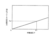
油圧ブレーキ20L,20R,21L,21Rは、例えばディスクブレーキであり、ディスクブレーキの両側面に押し付け可能なブレーキシューを駆動する油圧シリンダを備えている。そして、ブレーキ弁19から油圧ブレーキ20L,20R,21L,21Rの油圧シリンダに供給される作動油圧に応じてブレーキシューの押し付け力が変動することにより、油圧ブレーキ20L,20R,21L,21Rの制動力が変動するようになっている。このとき、図4に示すように、油圧ブレーキ20L,20R,21L,21Rの制動力は、作動油圧Pの増加(言い換えれば、ブレーキペダル18の踏込み量の増加)に応じて単調増加しており、例えばブレーキ弁19の作動油圧P1(言い換えれば、ブレーキペダル18の踏込み量θ1)において制動力Fa1が得られる。
The
ここで本実施形態の大きな特徴として、ブレーキ弁19から油圧ブレーキ20L,20R,21L,21Rに出力する作動油圧Pを検出する油圧センサ22が設けられており、制御装置14は、第2の機能(ブレーキ制御機能)として、油圧センサ22から入力した検出信号に対し所定の演算処理を行い、ブレーキ弁19の作動油圧Pが予め設定された所定値P1以上であるかどうか、すなわちブレーキペダル18の踏込み量が予め設定された所定値θ1以上であるかどうか判定するようになっている。そして、例えばブレーキ弁19の作動油圧Pが所定値P1以上である(すなわちブレーキペダル18の踏込み量が所定値θ1以上である)とき、インバータ26L,26Rを順変換器とし走行用モータ13L,13Rを発電機式リターダとして作動させ(詳細には、走行用モータ13L,13Rを発電機として運転させて運動エネルギーを電気エネルギーに変換してブレーキをかける)、その発電電力を放熱装置23に供給するようになっている。放熱装置23は、抵抗体に電流を流すことで走行用モータ13L,13Rの発電エネルギーを熱エネルギーに変換するとともに、抵抗体を冷却ファンによって冷却するようになっている。
Here, as a major feature of the present embodiment, a
図9は、上記制御装置14の機能構成を表すブロック図である。
FIG. 9 is a block diagram showing a functional configuration of the
この図9において、制御装置14は、油圧センサ22等からの入力信号に対し所定の演算処理を行うコントローラ24と、発電機11からの交流電流を直流電流に変換する整流器25と、逆変換器として動作した場合は整流器27からの直流電流を交流電流に変換して走行用モータ13L,13Rに供給する一方、順変換器として動作した場合は走行用モータ13L,13Rで発電した交流電流を直流電流に変換するインバータ26L,26Rと、インバータ25L,25Rと放熱装置23との接続状態又は遮断状態を切替えるチョッパ27(スイッチ回路)とを有している。
In FIG. 9, a
図5は、上記制御装置14のブレーキ制御機能に係わる制御処理内容を表すフローチャートである。
FIG. 5 is a flowchart showing the contents of control processing related to the brake control function of the
この図5において、制御装置14のコントローラ24は、まずステップ100において、油圧センサ22からの検出信号を読み込み、ステップ110に進んで、ブレーキ弁19から油圧ブレーキ20L,20R,21L,21Rに出力する作動油圧Pが所定値P1以上であるかどうか、すなわちブレーキペダル18の踏込み量が所定値θ1以上であるかどうかを判定する。例えば作動油圧Pが所定値P1未満である場合(言い換えれば、ブレーキペダル18の踏込み量が所定値θ1未満である場合)、ステップ110の判定が満たされず、ステップ100に戻って上記同様の手順を繰り返す。一方、例えば作動油圧Pが所定値P1以上である場合(言い換えれば、ブレーキペダル18の踏込み量が所定値θ1以上である場合)、ステップ110の判定が満たされ、ステップ120に移る。
In FIG. 5, the
ステップ120では、コントローラ24は、インバータ26L,26Rに順変換器として動作させる指令を出力し、ステップ130に進んで、チョッパ27に接続状態の切替え制御を行わせる指令を出力する。これにより、走行用モータ13L,13Rが発電機式リターダとして作動し、その発電した交流電流がインバータ26L,26Rを介し直流電流に変換されて、チョッパ27を介し放熱装置23に出力される。このとき、本実施形態では、図6に示すように、作動油圧PがP1以上の範囲では、発電機式リターダの制動力は最大値Fb_max(但し、実際には、最大値Fb_maxは車体速度に応じて変動する)が得られるようになっている。
In
以上のようにして本実施形態では、図7に示すように、ブレーキペダル18の踏込み量に応じて、油圧ブレーキ20L,20R,21L,21R及び発電機式リターダの総制動力が得られる。詳しくは、ブレーキペダル18の踏込み量がθ1未満の範囲では、その踏込み量に比例する油圧ブレーキ20L,20R,21L,21Rの制動力が得られ、踏込み量がθ1のときに総制動力がFa1となる。また、ブレーキペダル18の踏込み量がθ1以上の範囲では、踏込み量に比例する油圧ブレーキ20L,20R,21L,21Rの制動力と、発電機式リターダの制動力の最大値Fb_maxとの総和が得られるようになっている。
As described above, in the present embodiment, as shown in FIG. 7, the total braking force of the
次に、本実施形態の動作及び作用効果を説明する。 Next, the operation and effect of this embodiment will be described.
例えばダンプトラック1の減速又は停止を意図して、ブレーキペダル18の踏込み量が所定値θ1未満となるように運転者がブレーキペダル18を踏込んだ場合、ブレーキ弁19からブレーキペダル18の踏込み量に応じた作動油圧が出力され、油圧ブレーキ20L,20R,21L,21Rが作動する。これにより、車体速度に拘わらず、ブレーキペダル18の踏込み量に比例した油圧ブレーキ20L,20R,21L,21Rの制動力を得ることができる。その結果、例えばダンプトラック1を所定位置(例えばローディングサイト等)に停止させる場合に重要となるブレーキの微操作性能を維持することができる。
For example, when the driver depresses the
一方、例えばブレーキペダル18の踏込み量が所定値θ1以上となるように運転者がブレーキペダル18を踏込んだ場合は、油圧ブレーキ20L,20R,21L,21Rが作動するとともに、制御装置14は、前述した図5のステップ100を経てステップ110の判定が満たされ、ステップ120及び130において、走行用モータ13L,13Rを発電機式リターダとして作動させる。これにより、例えば油圧ブレーキ20L,20R,21L,21Rだけが作動する場合に比べ、制動力を高めることができる。
On the other hand, for example, when the driver depresses the
したがって、本実施形態においては、ブレーキの微操作性能を維持しつつ、ブレーキの制動力を高めることができる。 Therefore, in this embodiment, the braking force of the brake can be increased while maintaining the fine operation performance of the brake.
なお、上記一実施形態においては、ブレーキペダル18の踏込み量を検出する検出手段として、ブレーキ弁19から油圧ブレーキ20L,20R,21L,21Rに出力する作動油圧を検出する油圧センサ22を設けた場合を例にとって説明したが、これに限られない。すなわち、油圧センサ22に代えて、例えばブレーキペダル18の踏込み角度を検出する角度検出器等を設けてもよい。このような場合も、上記同様の効果を得ることができる。
In the above-described embodiment, when the
また、上記一実施形態においては、制御装置14は、作動油圧PがP1以上となるときに発電機式リターダの制動力は最大値Fb_maxが得られるように制御する場合を例にとって説明したが、これに限られない。すなわち、例えば作動油圧Pの増加に応じて発電機式リターダの制動力が連続的に増加するように制御してもよい(言い換えれば、ブレーキペダルの踏込み量に応じて発電機式リターダの制動力を連続的に変化させてもよい)。この場合も、上記同様の効果を得ることができる。
In the above embodiment, the
Claims (3)
前記エンジン(10)によって駆動する発電機(11)と、
前記発電機(11)で発電した電力により駆動する走行用モータ(13L,13R)と、
ブレーキペダル(18)の操作により、前記ブレーキペダル(18)の踏込み量が予め設定された所定値未満である場合も前記所定値以上である場合も作動するサービスブレーキ(20L,20R,21L,21R)とを備えた電気駆動ダンプトラックのブレーキシステムにおいて、
前記プレーキペダル(18)の踏込み量を検出する検出手段(22)と、
前記検出手段(22)で検出した前記ブレーキペダル(18)の踏込み量が前記所定値未満である場合に、前記走行用モータ(13L,13R)を発電機式リターダとして作動させず、前記検出手段(22)で検出した前記ブレーキペダル(18)の踏込み量が前記所定値以上である場合に、前記走行用モータ(13L,13R)を発電機式リターダとして作動させる制御手段(14)とを備えたことを特徴とする電気駆動ダンプトラックのブレーキシステム。An engine (10);
A generator (11) driven by the engine (10);
Traveling motors (13L, 13R) driven by the electric power generated by the generator (11);
Service brakes (20L, 20R, 21L, 21R) that operate both when the amount of depression of the brake pedal (18) is less than a predetermined value or greater than the predetermined value by operating the brake pedal (18). In an electrically driven dump truck brake system,
Detection means (22) for detecting the depression amount of the brake pedal (18);
When the depression amount of the brake pedal (18) detected by the detection means (22) is less than the predetermined value, the travel motors (13L, 13R) are not operated as a generator type retarder, and the detection means If the amount of depression of the brake is detected by (22) the pedal (18) is the predetermined value or more, and a said traction motor (13L, 13R) control means for operating as a generator type retarder (14) A brake system for an electrically driven dump truck.
Priority Applications (1)
| Application Number | Priority Date | Filing Date | Title |
|---|---|---|---|
| JP2008513851A JP5155155B2 (en) | 2006-09-05 | 2007-08-10 | Brake system for electric drive dump truck |
Applications Claiming Priority (4)
| Application Number | Priority Date | Filing Date | Title |
|---|---|---|---|
| JP2006240587 | 2006-09-05 | ||
| JP2006240587 | 2006-09-05 | ||
| PCT/JP2007/065765 WO2008029593A1 (en) | 2006-09-05 | 2007-08-10 | Brake system of electrically driven dump truck |
| JP2008513851A JP5155155B2 (en) | 2006-09-05 | 2007-08-10 | Brake system for electric drive dump truck |
Publications (2)
| Publication Number | Publication Date |
|---|---|
| JPWO2008029593A1 JPWO2008029593A1 (en) | 2010-01-21 |
| JP5155155B2 true JP5155155B2 (en) | 2013-02-27 |
Family
ID=39157035
Family Applications (1)
| Application Number | Title | Priority Date | Filing Date |
|---|---|---|---|
| JP2008513851A Active JP5155155B2 (en) | 2006-09-05 | 2007-08-10 | Brake system for electric drive dump truck |
Country Status (5)
| Country | Link |
|---|---|
| US (1) | US8376476B2 (en) |
| JP (1) | JP5155155B2 (en) |
| AU (1) | AU2007292710B2 (en) |
| DE (1) | DE112007000071B4 (en) |
| WO (1) | WO2008029593A1 (en) |
Families Citing this family (16)
| Publication number | Priority date | Publication date | Assignee | Title |
|---|---|---|---|---|
| JP5215956B2 (en) * | 2008-09-03 | 2013-06-19 | 日立建機株式会社 | Dump truck |
| JP2010183687A (en) * | 2009-02-04 | 2010-08-19 | Hitachi Constr Mach Co Ltd | Device and method for driving support of motor-driven truck |
| JP5951704B2 (en) * | 2009-04-02 | 2016-07-13 | 株式会社東芝 | Regenerative brake device and vehicle equipped with regenerative brake device |
| DE102010003076A1 (en) * | 2009-08-05 | 2011-08-18 | Continental Automotive GmbH, 30165 | Method for controlling a wheel brake slip and wheel brake slip control system for a vehicle with an electric drive |
| DE102010029386B4 (en) * | 2010-05-27 | 2025-12-04 | Zf Friedrichshafen Ag | Method for operating a drive train |
| JP5415619B2 (en) * | 2010-07-15 | 2014-02-12 | 日立建機株式会社 | Electric work vehicle |
| DE102011075968A1 (en) * | 2011-05-17 | 2012-11-22 | Robert Bosch Gmbh | Control device for a brake system of a vehicle and method for operating a brake system of a vehicle |
| US20130187353A1 (en) * | 2012-01-23 | 2013-07-25 | Erwin Mock | Multi-brake system having independent control |
| CN104955698B (en) * | 2013-03-29 | 2017-03-08 | 日立建机株式会社 | Engine Rotable Control System |
| JP7105526B2 (en) * | 2018-08-10 | 2022-07-25 | 日立建機株式会社 | work vehicle |
| US20220194232A1 (en) * | 2019-05-06 | 2022-06-23 | Aikar Technology Inc. | A vehicle braking method and system |
| US11951873B2 (en) | 2021-03-30 | 2024-04-09 | Toyota Motor Engineering & Manufacturing North America, Inc. | Continuously adaptable braking pedal map system |
| JP7280920B2 (en) * | 2021-06-02 | 2023-05-24 | 日立建機株式会社 | Dump truck |
| DE102021114497A1 (en) | 2021-06-07 | 2022-12-08 | Zf Cv Systems Global Gmbh | Brake system of a motor vehicle and method for controlling the same |
| SE544948C2 (en) * | 2021-06-17 | 2023-02-07 | Scania Cv Ab | System for braking an electrified vehicle |
| US12115904B2 (en) * | 2023-02-13 | 2024-10-15 | Ford Global Techologies, Llc | Redundant system for brake light operation |
Citations (11)
| Publication number | Priority date | Publication date | Assignee | Title |
|---|---|---|---|---|
| US4307300A (en) * | 1978-03-02 | 1981-12-22 | Kabushiki Kaisha Komatsu Seisakusho | Dump truck with safety circuit |
| JPS57930A (en) * | 1980-06-04 | 1982-01-06 | Komatsu Ltd | Automatic controller for retarder braking |
| JPS57931A (en) * | 1980-06-05 | 1982-01-06 | Komatsu Ltd | Automatic controller for retarder braking |
| JPH04355603A (en) * | 1991-06-03 | 1992-12-09 | Honda Motor Co Ltd | Brake controller for electric automobile and controlling method thereof |
| JPH05501687A (en) * | 1989-11-30 | 1993-04-02 | ルトールネオー・インコーポレーテッド | Method and apparatus for propelling and slowing off-road transport vehicles |
| JPH05111109A (en) * | 1991-10-08 | 1993-04-30 | Mitsubishi Heavy Ind Ltd | Control method for electric vehicle driven by internal combustion engine |
| JPH07228242A (en) * | 1993-12-20 | 1995-08-29 | Toyo Umpanki Co Ltd | Auxiliary brake device for industrial vehicle |
| JP2000224709A (en) * | 1999-01-29 | 2000-08-11 | Nissan Diesel Motor Co Ltd | Power supply |
| JP2003269205A (en) * | 2002-03-15 | 2003-09-25 | Hitachi Constr Mach Co Ltd | Operation control device of wheel construction machinery |
| DE10313519A1 (en) * | 2002-03-25 | 2003-10-23 | Ford Motor Co | Service brake system for a hybrid electric vehicle |
| JP2006166684A (en) * | 2004-12-10 | 2006-06-22 | Hitachi Ltd | Vehicle electric drive device, vehicle electric control device, and vehicle electric drive method |
Family Cites Families (8)
| Publication number | Priority date | Publication date | Assignee | Title |
|---|---|---|---|---|
| DE19810656A1 (en) | 1998-03-12 | 1999-09-16 | Itt Mfg Enterprises Inc | Braking control method for electric or hybrid vehicles |
| JP2004155390A (en) * | 2002-11-08 | 2004-06-03 | Nissan Motor Co Ltd | Vehicle braking system |
| EP1470979B1 (en) * | 2003-04-24 | 2006-12-27 | Nissan Motor Company Limited | Vehicle brake system |
| JP4355164B2 (en) * | 2003-04-24 | 2009-10-28 | 日産自動車株式会社 | Vehicle braking device |
| KR100534709B1 (en) * | 2003-12-30 | 2005-12-07 | 현대자동차주식회사 | Method and apparatus for controlling regenerative braking of electric vehicle |
| US7232192B2 (en) * | 2004-07-01 | 2007-06-19 | Ford Global Technologies, Llc | Deadband regenerative braking control for hydraulic hybrid vehicle powertrain |
| JP2007101256A (en) * | 2005-09-30 | 2007-04-19 | Fujifilm Corp | X-ray imaging apparatus and X-ray CT apparatus |
| WO2007060813A1 (en) * | 2005-11-22 | 2007-05-31 | Konica Minolta Medical & Graphic, Inc. | Scintillator plate |
-
2007
- 2007-08-10 US US12/090,940 patent/US8376476B2/en active Active
- 2007-08-10 DE DE112007000071.6T patent/DE112007000071B4/en active Active
- 2007-08-10 AU AU2007292710A patent/AU2007292710B2/en active Active
- 2007-08-10 WO PCT/JP2007/065765 patent/WO2008029593A1/en not_active Ceased
- 2007-08-10 JP JP2008513851A patent/JP5155155B2/en active Active
Patent Citations (12)
| Publication number | Priority date | Publication date | Assignee | Title |
|---|---|---|---|---|
| US4307300A (en) * | 1978-03-02 | 1981-12-22 | Kabushiki Kaisha Komatsu Seisakusho | Dump truck with safety circuit |
| JPS57930A (en) * | 1980-06-04 | 1982-01-06 | Komatsu Ltd | Automatic controller for retarder braking |
| JPS57931A (en) * | 1980-06-05 | 1982-01-06 | Komatsu Ltd | Automatic controller for retarder braking |
| JPH05501687A (en) * | 1989-11-30 | 1993-04-02 | ルトールネオー・インコーポレーテッド | Method and apparatus for propelling and slowing off-road transport vehicles |
| JPH04355603A (en) * | 1991-06-03 | 1992-12-09 | Honda Motor Co Ltd | Brake controller for electric automobile and controlling method thereof |
| US5322352A (en) * | 1991-06-03 | 1994-06-21 | Honda Giken Kogyo Kabushiki Kaisha | Electric vehicle regenerative and friction braking control system |
| JPH05111109A (en) * | 1991-10-08 | 1993-04-30 | Mitsubishi Heavy Ind Ltd | Control method for electric vehicle driven by internal combustion engine |
| JPH07228242A (en) * | 1993-12-20 | 1995-08-29 | Toyo Umpanki Co Ltd | Auxiliary brake device for industrial vehicle |
| JP2000224709A (en) * | 1999-01-29 | 2000-08-11 | Nissan Diesel Motor Co Ltd | Power supply |
| JP2003269205A (en) * | 2002-03-15 | 2003-09-25 | Hitachi Constr Mach Co Ltd | Operation control device of wheel construction machinery |
| DE10313519A1 (en) * | 2002-03-25 | 2003-10-23 | Ford Motor Co | Service brake system for a hybrid electric vehicle |
| JP2006166684A (en) * | 2004-12-10 | 2006-06-22 | Hitachi Ltd | Vehicle electric drive device, vehicle electric control device, and vehicle electric drive method |
Also Published As
| Publication number | Publication date |
|---|---|
| AU2007292710B2 (en) | 2010-05-13 |
| US8376476B2 (en) | 2013-02-19 |
| DE112007000071T5 (en) | 2008-08-28 |
| JPWO2008029593A1 (en) | 2010-01-21 |
| WO2008029593A1 (en) | 2008-03-13 |
| AU2007292710A1 (en) | 2008-03-13 |
| US20090179486A1 (en) | 2009-07-16 |
| DE112007000071B4 (en) | 2016-12-15 |
Similar Documents
| Publication | Publication Date | Title |
|---|---|---|
| JP5155155B2 (en) | Brake system for electric drive dump truck | |
| JP5222329B2 (en) | Braking device for vehicle | |
| JP5087358B2 (en) | Pedal lock control device for work vehicle | |
| WO2017002557A1 (en) | Acceleration and deceleration control device | |
| JP5560797B2 (en) | Work vehicle traveling device | |
| JP2019115226A (en) | Control device, control method and control system for electric vehicle | |
| WO1997028030A1 (en) | Apparatus for controlling brake of vehicle | |
| WO2015097911A1 (en) | Forklift and forklift control method | |
| CN103328283A (en) | Hydraulic drive of a wheel-type work machine | |
| JP2015112895A (en) | Hybrid electric work vehicle | |
| JP5807805B2 (en) | Vehicle regenerative brake control device | |
| CN102632960B (en) | Brake system for motorcycle | |
| US20150328992A1 (en) | System and method for braking of machine | |
| WO2007029486A1 (en) | Hydraulic drive device for dump truck | |
| JP7481275B2 (en) | Work vehicles | |
| JP4069795B2 (en) | Hydraulic travel drive device | |
| JP5087359B2 (en) | Pedal lock control device for work vehicle | |
| JP2023145161A (en) | work vehicle | |
| JP3407057B2 (en) | Regenerative brake control device for electric vehicles | |
| JPH10229608A (en) | Electric vehicle braking system | |
| JP2009038922A (en) | Electric vehicle regenerative braking force control device | |
| JP2004187445A (en) | Electric vehicle braking system | |
| WO2001066977A1 (en) | Drivingly traveling device for industrial vehicle and brake device of the drivingly traveling device | |
| WO2019176795A1 (en) | Reaction force application device | |
| JP7826151B2 (en) | Evacuation driving control device |
Legal Events
| Date | Code | Title | Description |
|---|---|---|---|
| A621 | Written request for application examination |
Free format text: JAPANESE INTERMEDIATE CODE: A621 Effective date: 20100216 |
|
| A131 | Notification of reasons for refusal |
Free format text: JAPANESE INTERMEDIATE CODE: A131 Effective date: 20120703 |
|
| A521 | Request for written amendment filed |
Free format text: JAPANESE INTERMEDIATE CODE: A523 Effective date: 20120807 |
|
| TRDD | Decision of grant or rejection written | ||
| A01 | Written decision to grant a patent or to grant a registration (utility model) |
Free format text: JAPANESE INTERMEDIATE CODE: A01 Effective date: 20121204 |
|
| A61 | First payment of annual fees (during grant procedure) |
Free format text: JAPANESE INTERMEDIATE CODE: A61 Effective date: 20121206 |
|
| FPAY | Renewal fee payment (event date is renewal date of database) |
Free format text: PAYMENT UNTIL: 20151214 Year of fee payment: 3 |
|
| R150 | Certificate of patent or registration of utility model |
Ref document number: 5155155 Country of ref document: JP Free format text: JAPANESE INTERMEDIATE CODE: R150 Free format text: JAPANESE INTERMEDIATE CODE: R150 |