JP5185162B2 - シフト装置 - Google Patents
シフト装置 Download PDFInfo
- Publication number
- JP5185162B2 JP5185162B2 JP2009051126A JP2009051126A JP5185162B2 JP 5185162 B2 JP5185162 B2 JP 5185162B2 JP 2009051126 A JP2009051126 A JP 2009051126A JP 2009051126 A JP2009051126 A JP 2009051126A JP 5185162 B2 JP5185162 B2 JP 5185162B2
- Authority
- JP
- Japan
- Prior art keywords
- lever
- block
- check
- shift
- gate
- Prior art date
- Legal status (The legal status is an assumption and is not a legal conclusion. Google has not performed a legal analysis and makes no representation as to the accuracy of the status listed.)
- Expired - Fee Related
Links
- 238000001514 detection method Methods 0.000 claims description 31
- 230000007246 mechanism Effects 0.000 claims description 27
- 230000003584 silencer Effects 0.000 claims description 12
- 229920000642 polymer Polymers 0.000 claims description 4
- 238000004581 coalescence Methods 0.000 claims 1
- 230000007935 neutral effect Effects 0.000 description 8
- 230000030279 gene silencing Effects 0.000 description 6
- 230000001105 regulatory effect Effects 0.000 description 5
- 230000000694 effects Effects 0.000 description 4
- 230000037431 insertion Effects 0.000 description 4
- 238000003780 insertion Methods 0.000 description 4
- 230000015572 biosynthetic process Effects 0.000 description 3
- 230000005540 biological transmission Effects 0.000 description 2
- 230000008859 change Effects 0.000 description 1
- 210000000078 claw Anatomy 0.000 description 1
- 230000009467 reduction Effects 0.000 description 1
- 239000011347 resin Substances 0.000 description 1
- 229920005989 resin Polymers 0.000 description 1
- 230000004044 response Effects 0.000 description 1
Images


Classifications
-
- F—MECHANICAL ENGINEERING; LIGHTING; HEATING; WEAPONS; BLASTING
- F16—ENGINEERING ELEMENTS AND UNITS; GENERAL MEASURES FOR PRODUCING AND MAINTAINING EFFECTIVE FUNCTIONING OF MACHINES OR INSTALLATIONS; THERMAL INSULATION IN GENERAL
- F16H—GEARING
- F16H59/00—Control inputs to control units of change-speed- or reversing-gearings for conveying rotary motion
- F16H59/02—Selector apparatus
- F16H59/08—Range selector apparatus
- F16H59/10—Range selector apparatus comprising levers
- F16H59/105—Range selector apparatus comprising levers consisting of electrical switches or sensors
-
- F—MECHANICAL ENGINEERING; LIGHTING; HEATING; WEAPONS; BLASTING
- F16—ENGINEERING ELEMENTS AND UNITS; GENERAL MEASURES FOR PRODUCING AND MAINTAINING EFFECTIVE FUNCTIONING OF MACHINES OR INSTALLATIONS; THERMAL INSULATION IN GENERAL
- F16H—GEARING
- F16H61/00—Control functions within control units of change-speed- or reversing-gearings for conveying rotary motion ; Control of exclusively fluid gearing, friction gearing, gearings with endless flexible members or other particular types of gearing
- F16H61/24—Providing feel, e.g. to enable selection
Landscapes
- Engineering & Computer Science (AREA)
- General Engineering & Computer Science (AREA)
- Mechanical Engineering (AREA)
- Arrangement Or Mounting Of Control Devices For Change-Speed Gearing (AREA)
Description
前記ゲートブロックと前記チェックブロックとを単一の合体ブロックとして一体成形し、当該合体ブロックを、前記シフトレバーを支持する前記筺体の側壁に形成された取付穴に取り付けたことを特徴とする。
また、ゲートピンとレバー位置出力部とチェック部とを、これらの順に一列に配置したので、ゲートピンとレバー位置出力部とチェック部との相対位置精度をさらに容易に高めることができる。
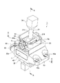
図1〜図5は本発明の第1の実施形態にかかるシフト装置を示し、図1はシフト装置の全体斜視図、図2はシフト装置の分解斜視図、図3は図1中A−A線に沿った断面図、図4は図1中B−B線に沿った断面図、図5はシフトレバーで操作されるポジション位置の配置を示す説明図である。
図6〜図8は本発明の第2の実施形態を示し、図6はチェックブロックを組み付けようとする状態の断面図、図7はチェックブロックをメインケースに組み付けた状態を示す断面斜視図、図8はチェックブロックをメインケースに組み付けた状態を示す断面図である。なお、第1の実施形態と同一構成部分には同一符号を付し、重複する説明は省略する。
3 レバー位置検出部
4 レバー規制部
5 チェック機構部
6 メインケース(筺体)
7 合体ブロック
21 シフトレバー
31 レバー位置出力部
32 ポジションセンサ(検出本体部)
41 ゲートピン
42 ゲートブロック
43 消音ダンパ(消音部材)
51 チェック部
52 チェックブロック
421 ゲート溝部
522 押さえ部
Claims (5)
- 2つの回転軸を介して筐体に支持され、シフト方向、およびセレクト方向に初期位置から操作位置へ回動可能なシフトレバーと、
前記シフトレバーの位置を検出するレバー位置検出部と、
前記シフトレバーの移動方向を規制するレバー規制部と、
前記シフトレバーを前記操作位置から前記初期位置に復帰させるチェック機構部と、
を備えたシフト装置において、
前記レバー位置検出部は、前記シフトレバーの前記回転軸の下方にほぼ扇形に形成される略扇形状部の下端中央に配置されて前記シフトレバーと一体に挙動するレバー位置出力部と、当該レバー位置出力部と係合し、当該レバー位置出力部の位置によってレバー選択位置を検出する検出本体部と、を備え、
前記レバー規制部は、前記シフトレバーと一体に挙動するゲートピンと、当該ゲートピンをガイドするゲート溝部を有するゲートブロックと、を備え、
前記チェック機構部は、前記シフトレバーと一体に挙動するチェック部と、当該チェック部をガイドするチェックブロックと、を備え、
前記シフトレバーの前記略扇形状部に、前記レバー位置出力部と、前記ゲートピンと、前記チェック部と、を一体に設けつつ、前記ゲートピンと前記レバー位置出力部と前記チェック部とを、これらの順に一列に配置したことを特徴とするシフト装置。 - 前記筐体は、前記レバー規制部と前記チェック機構部とが収納される収納部を備え、
前記検出本体部を、前記収納部の下面下方に配置するとともに、前記検出本体部に設けたセンサ作動ピンが前記筐体の下面に設けられた開口部を貫通して、前記レバー位置出力部に回転自在に嵌合したことを特徴とする請求項1に記載のシフト装置。 - 前記ゲートブロックと前記チェックブロックとを単一の合体ブロックとして一体成形し、当該合体ブロックを、前記シフトレバーを支持する前記筺体の側壁に形成された取付穴に取り付けたことを特徴とする請求項1または2に記載のシフト装置。
- 前記検出本体部を、前記合体ブロックに直接に取り付けたことを特徴とする請求項3に記載のシフト装置。
- 前記ゲートブロックを覆う消音部材を備え、
前記ゲートブロックと前記チェックブロックとを別体に形成するとともに、当該ゲートブロックを前記シフトレバーを支持する前記筺体と一体成形し、
前記チェックブロックに、当該チェックブロックを前記筺体に挿入して前記ゲートブロックに結合した際に、前記消音部材を押さえて前記ゲートブロックに固定する押さえ部を設けたことを特徴とする請求項1に記載のシフト装置。
Priority Applications (1)
| Application Number | Priority Date | Filing Date | Title |
|---|---|---|---|
| JP2009051126A JP5185162B2 (ja) | 2009-03-04 | 2009-03-04 | シフト装置 |
Applications Claiming Priority (1)
| Application Number | Priority Date | Filing Date | Title |
|---|---|---|---|
| JP2009051126A JP5185162B2 (ja) | 2009-03-04 | 2009-03-04 | シフト装置 |
Publications (2)
| Publication Number | Publication Date |
|---|---|
| JP2010202083A JP2010202083A (ja) | 2010-09-16 |
| JP5185162B2 true JP5185162B2 (ja) | 2013-04-17 |
Family
ID=42964002
Family Applications (1)
| Application Number | Title | Priority Date | Filing Date |
|---|---|---|---|
| JP2009051126A Expired - Fee Related JP5185162B2 (ja) | 2009-03-04 | 2009-03-04 | シフト装置 |
Country Status (1)
| Country | Link |
|---|---|
| JP (1) | JP5185162B2 (ja) |
Families Citing this family (2)
| Publication number | Priority date | Publication date | Assignee | Title |
|---|---|---|---|---|
| JP6129661B2 (ja) * | 2013-07-01 | 2017-05-17 | 株式会社東海理化電機製作所 | シフト装置 |
| JP6449200B2 (ja) | 2016-07-28 | 2019-01-09 | 株式会社東海理化電機製作所 | シフト装置 |
Family Cites Families (5)
| Publication number | Priority date | Publication date | Assignee | Title |
|---|---|---|---|---|
| JP2908955B2 (ja) * | 1993-02-25 | 1999-06-23 | 富士機工株式会社 | 車両用変速装置 |
| JP3126866B2 (ja) * | 1993-03-31 | 2001-01-22 | 富士機工株式会社 | 車両用変速装置 |
| JP3528344B2 (ja) * | 1995-06-21 | 2004-05-17 | アイシン・エィ・ダブリュ株式会社 | 車両用自動変速機のシフト装置 |
| SE517453C2 (sv) * | 1997-06-27 | 2002-06-11 | Kongsberg Automotive Ab | Manöveranordning |
| JP2006218940A (ja) * | 2005-02-09 | 2006-08-24 | Tokai Rika Co Ltd | シフトレバー装置 |
-
2009
- 2009-03-04 JP JP2009051126A patent/JP5185162B2/ja not_active Expired - Fee Related
Also Published As
| Publication number | Publication date |
|---|---|
| JP2010202083A (ja) | 2010-09-16 |
Similar Documents
| Publication | Publication Date | Title |
|---|---|---|
| US20190316673A1 (en) | Shifting device | |
| JP5815545B2 (ja) | 変速機用のシフトないしセレクトレバーのポジションを検知するための装置、並びに自動車の変速機用のシフト装置 | |
| JP4886606B2 (ja) | レバー装置 | |
| JP6683585B2 (ja) | シフト装置 | |
| JP6576748B2 (ja) | シフト装置 | |
| JP5797444B2 (ja) | ジョイスティック装置 | |
| JP5355256B2 (ja) | レバー位置検出装置 | |
| EP1589322B1 (en) | Device for detecting rotation in two directions and shift lever device | |
| JP6023011B2 (ja) | 位置検出装置 | |
| JP6420687B2 (ja) | 位置検出装置 | |
| JP5185162B2 (ja) | シフト装置 | |
| JP4943911B2 (ja) | シフトレバー装置 | |
| JP4813386B2 (ja) | シフトレバー装置 | |
| US7541550B2 (en) | Turn signal switch device | |
| KR101874700B1 (ko) | 레인지 로터리 센서 유니트 | |
| JP5303434B2 (ja) | シフト装置 | |
| WO2019054153A1 (ja) | シフト装置 | |
| JP2009063103A (ja) | 自動変速機のインヒビタスイッチ | |
| JP2010221972A (ja) | シフト装置 | |
| JP2006240425A (ja) | シフトレバー装置 | |
| JP2006290215A (ja) | レンジ検出装置 | |
| JP5117814B2 (ja) | シフトレバー装置 | |
| KR20080008081A (ko) | 변속기의 중립 감지용 디텐트 장치 | |
| JP6738186B2 (ja) | シフト装置 | |
| JP4733591B2 (ja) | シフト装置 |
Legal Events
| Date | Code | Title | Description |
|---|---|---|---|
| A621 | Written request for application examination |
Free format text: JAPANESE INTERMEDIATE CODE: A621 Effective date: 20111124 |
|
| A977 | Report on retrieval |
Free format text: JAPANESE INTERMEDIATE CODE: A971007 Effective date: 20120830 |
|
| A131 | Notification of reasons for refusal |
Free format text: JAPANESE INTERMEDIATE CODE: A131 Effective date: 20120911 |
|
| A521 | Request for written amendment filed |
Free format text: JAPANESE INTERMEDIATE CODE: A523 Effective date: 20121108 |
|
| TRDD | Decision of grant or rejection written | ||
| A01 | Written decision to grant a patent or to grant a registration (utility model) |
Free format text: JAPANESE INTERMEDIATE CODE: A01 Effective date: 20121219 |
|
| A61 | First payment of annual fees (during grant procedure) |
Free format text: JAPANESE INTERMEDIATE CODE: A61 Effective date: 20130117 |
|
| R150 | Certificate of patent or registration of utility model |
Ref document number: 5185162 Country of ref document: JP Free format text: JAPANESE INTERMEDIATE CODE: R150 Free format text: JAPANESE INTERMEDIATE CODE: R150 |
|
| FPAY | Renewal fee payment (event date is renewal date of database) |
Free format text: PAYMENT UNTIL: 20160125 Year of fee payment: 3 |
|
| R250 | Receipt of annual fees |
Free format text: JAPANESE INTERMEDIATE CODE: R250 |
|
| R250 | Receipt of annual fees |
Free format text: JAPANESE INTERMEDIATE CODE: R250 |
|
| R250 | Receipt of annual fees |
Free format text: JAPANESE INTERMEDIATE CODE: R250 |
|
| R250 | Receipt of annual fees |
Free format text: JAPANESE INTERMEDIATE CODE: R250 |
|
| R250 | Receipt of annual fees |
Free format text: JAPANESE INTERMEDIATE CODE: R250 |
|
| R250 | Receipt of annual fees |
Free format text: JAPANESE INTERMEDIATE CODE: R250 |
|
| LAPS | Cancellation because of no payment of annual fees |