JP5191994B2 - Neck lift procedure and instrument for performing it - Google Patents
Neck lift procedure and instrument for performing it Download PDFInfo
- Publication number
- JP5191994B2 JP5191994B2 JP2009540435A JP2009540435A JP5191994B2 JP 5191994 B2 JP5191994 B2 JP 5191994B2 JP 2009540435 A JP2009540435 A JP 2009540435A JP 2009540435 A JP2009540435 A JP 2009540435A JP 5191994 B2 JP5191994 B2 JP 5191994B2
- Authority
- JP
- Japan
- Prior art keywords
- threading device
- suture
- skin
- tube
- threading
- Prior art date
- Legal status (The legal status is an assumption and is not a legal conclusion. Google has not performed a legal analysis and makes no representation as to the accuracy of the status listed.)
- Active
Links
Images


Classifications
-
- A—HUMAN NECESSITIES
- A61—MEDICAL OR VETERINARY SCIENCE; HYGIENE
- A61B—DIAGNOSIS; SURGERY; IDENTIFICATION
- A61B17/00—Surgical instruments, devices or methods
- A61B17/04—Surgical instruments, devices or methods for suturing wounds; Holders or packages for needles or suture materials
- A61B17/0401—Suture anchors, buttons or pledgets, i.e. means for attaching sutures to bone, cartilage or soft tissue; Instruments for applying or removing suture anchors
-
- A—HUMAN NECESSITIES
- A61—MEDICAL OR VETERINARY SCIENCE; HYGIENE
- A61B—DIAGNOSIS; SURGERY; IDENTIFICATION
- A61B17/00—Surgical instruments, devices or methods
-
- A—HUMAN NECESSITIES
- A61—MEDICAL OR VETERINARY SCIENCE; HYGIENE
- A61B—DIAGNOSIS; SURGERY; IDENTIFICATION
- A61B17/00—Surgical instruments, devices or methods
- A61B17/04—Surgical instruments, devices or methods for suturing wounds; Holders or packages for needles or suture materials
- A61B17/0482—Needle or suture guides
-
- A—HUMAN NECESSITIES
- A61—MEDICAL OR VETERINARY SCIENCE; HYGIENE
- A61B—DIAGNOSIS; SURGERY; IDENTIFICATION
- A61B17/00—Surgical instruments, devices or methods
- A61B17/04—Surgical instruments, devices or methods for suturing wounds; Holders or packages for needles or suture materials
- A61B17/0483—Hand-held instruments for holding sutures
-
- A—HUMAN NECESSITIES
- A61—MEDICAL OR VETERINARY SCIENCE; HYGIENE
- A61B—DIAGNOSIS; SURGERY; IDENTIFICATION
- A61B17/00—Surgical instruments, devices or methods
- A61B17/04—Surgical instruments, devices or methods for suturing wounds; Holders or packages for needles or suture materials
- A61B17/06—Needles ; Sutures; Needle-suture combinations; Holders or packages for needles or suture materials
- A61B17/06066—Needles, e.g. needle tip configurations
-
- A—HUMAN NECESSITIES
- A61—MEDICAL OR VETERINARY SCIENCE; HYGIENE
- A61B—DIAGNOSIS; SURGERY; IDENTIFICATION
- A61B17/00—Surgical instruments, devices or methods
- A61B17/04—Surgical instruments, devices or methods for suturing wounds; Holders or packages for needles or suture materials
- A61B17/06—Needles ; Sutures; Needle-suture combinations; Holders or packages for needles or suture materials
- A61B17/06166—Sutures
-
- A—HUMAN NECESSITIES
- A61—MEDICAL OR VETERINARY SCIENCE; HYGIENE
- A61B—DIAGNOSIS; SURGERY; IDENTIFICATION
- A61B17/00—Surgical instruments, devices or methods
- A61B17/04—Surgical instruments, devices or methods for suturing wounds; Holders or packages for needles or suture materials
- A61B17/0485—Devices or means, e.g. loops, for capturing the suture thread and threading it through an opening of a suturing instrument or needle eyelet
-
- A—HUMAN NECESSITIES
- A61—MEDICAL OR VETERINARY SCIENCE; HYGIENE
- A61B—DIAGNOSIS; SURGERY; IDENTIFICATION
- A61B17/00—Surgical instruments, devices or methods
- A61B17/32—Surgical cutting instruments
- A61B17/3209—Incision instruments
- A61B17/32093—Incision instruments for skin incisions
-
- A—HUMAN NECESSITIES
- A61—MEDICAL OR VETERINARY SCIENCE; HYGIENE
- A61B—DIAGNOSIS; SURGERY; IDENTIFICATION
- A61B17/00—Surgical instruments, devices or methods
- A61B2017/00743—Type of operation; Specification of treatment sites
- A61B2017/00792—Plastic surgery
-
- A—HUMAN NECESSITIES
- A61—MEDICAL OR VETERINARY SCIENCE; HYGIENE
- A61B—DIAGNOSIS; SURGERY; IDENTIFICATION
- A61B17/00—Surgical instruments, devices or methods
- A61B17/04—Surgical instruments, devices or methods for suturing wounds; Holders or packages for needles or suture materials
- A61B17/0401—Suture anchors, buttons or pledgets, i.e. means for attaching sutures to bone, cartilage or soft tissue; Instruments for applying or removing suture anchors
- A61B2017/0403—Dowels
-
- A—HUMAN NECESSITIES
- A61—MEDICAL OR VETERINARY SCIENCE; HYGIENE
- A61B—DIAGNOSIS; SURGERY; IDENTIFICATION
- A61B17/00—Surgical instruments, devices or methods
- A61B17/04—Surgical instruments, devices or methods for suturing wounds; Holders or packages for needles or suture materials
- A61B17/0401—Suture anchors, buttons or pledgets, i.e. means for attaching sutures to bone, cartilage or soft tissue; Instruments for applying or removing suture anchors
- A61B2017/0406—Pledgets
-
- A—HUMAN NECESSITIES
- A61—MEDICAL OR VETERINARY SCIENCE; HYGIENE
- A61B—DIAGNOSIS; SURGERY; IDENTIFICATION
- A61B17/00—Surgical instruments, devices or methods
- A61B17/04—Surgical instruments, devices or methods for suturing wounds; Holders or packages for needles or suture materials
- A61B17/0401—Suture anchors, buttons or pledgets, i.e. means for attaching sutures to bone, cartilage or soft tissue; Instruments for applying or removing suture anchors
- A61B2017/0409—Instruments for applying suture anchors
-
- A—HUMAN NECESSITIES
- A61—MEDICAL OR VETERINARY SCIENCE; HYGIENE
- A61B—DIAGNOSIS; SURGERY; IDENTIFICATION
- A61B17/00—Surgical instruments, devices or methods
- A61B17/04—Surgical instruments, devices or methods for suturing wounds; Holders or packages for needles or suture materials
- A61B17/0401—Suture anchors, buttons or pledgets, i.e. means for attaching sutures to bone, cartilage or soft tissue; Instruments for applying or removing suture anchors
- A61B2017/0414—Suture anchors, buttons or pledgets, i.e. means for attaching sutures to bone, cartilage or soft tissue; Instruments for applying or removing suture anchors having a suture-receiving opening, e.g. lateral opening
-
- A—HUMAN NECESSITIES
- A61—MEDICAL OR VETERINARY SCIENCE; HYGIENE
- A61B—DIAGNOSIS; SURGERY; IDENTIFICATION
- A61B17/00—Surgical instruments, devices or methods
- A61B17/04—Surgical instruments, devices or methods for suturing wounds; Holders or packages for needles or suture materials
- A61B17/0401—Suture anchors, buttons or pledgets, i.e. means for attaching sutures to bone, cartilage or soft tissue; Instruments for applying or removing suture anchors
- A61B2017/042—Suture anchors, buttons or pledgets, i.e. means for attaching sutures to bone, cartilage or soft tissue; Instruments for applying or removing suture anchors plastically deformed during insertion
- A61B2017/0422—Suture anchors, buttons or pledgets, i.e. means for attaching sutures to bone, cartilage or soft tissue; Instruments for applying or removing suture anchors plastically deformed during insertion by insertion of a separate member into the body of the anchor
- A61B2017/0425—Suture anchors, buttons or pledgets, i.e. means for attaching sutures to bone, cartilage or soft tissue; Instruments for applying or removing suture anchors plastically deformed during insertion by insertion of a separate member into the body of the anchor the anchor or the separate member comprising threads, e.g. a set screw in the anchor
-
- A—HUMAN NECESSITIES
- A61—MEDICAL OR VETERINARY SCIENCE; HYGIENE
- A61B—DIAGNOSIS; SURGERY; IDENTIFICATION
- A61B17/00—Surgical instruments, devices or methods
- A61B17/04—Surgical instruments, devices or methods for suturing wounds; Holders or packages for needles or suture materials
- A61B17/0401—Suture anchors, buttons or pledgets, i.e. means for attaching sutures to bone, cartilage or soft tissue; Instruments for applying or removing suture anchors
- A61B2017/044—Suture anchors, buttons or pledgets, i.e. means for attaching sutures to bone, cartilage or soft tissue; Instruments for applying or removing suture anchors with a threaded shaft, e.g. screws
-
- A—HUMAN NECESSITIES
- A61—MEDICAL OR VETERINARY SCIENCE; HYGIENE
- A61B—DIAGNOSIS; SURGERY; IDENTIFICATION
- A61B17/00—Surgical instruments, devices or methods
- A61B17/04—Surgical instruments, devices or methods for suturing wounds; Holders or packages for needles or suture materials
- A61B2017/0496—Surgical instruments, devices or methods for suturing wounds; Holders or packages for needles or suture materials for tensioning sutures
-
- A—HUMAN NECESSITIES
- A61—MEDICAL OR VETERINARY SCIENCE; HYGIENE
- A61B—DIAGNOSIS; SURGERY; IDENTIFICATION
- A61B90/00—Instruments, implements or accessories specially adapted for surgery or diagnosis and not covered by any of the groups A61B1/00 - A61B50/00, e.g. for luxation treatment or for protecting wound edges
- A61B90/39—Markers, e.g. radio-opaque or breast lesions markers
- A61B2090/3904—Markers, e.g. radio-opaque or breast lesions markers specially adapted for marking specified tissue
-
- A—HUMAN NECESSITIES
- A61—MEDICAL OR VETERINARY SCIENCE; HYGIENE
- A61B—DIAGNOSIS; SURGERY; IDENTIFICATION
- A61B90/00—Instruments, implements or accessories specially adapted for surgery or diagnosis and not covered by any of the groups A61B1/00 - A61B50/00, e.g. for luxation treatment or for protecting wound edges
- A61B90/39—Markers, e.g. radio-opaque or breast lesions markers
- A61B2090/3937—Visible markers
- A61B2090/395—Visible markers with marking agent for marking skin or other tissue
-
- Y—GENERAL TAGGING OF NEW TECHNOLOGICAL DEVELOPMENTS; GENERAL TAGGING OF CROSS-SECTIONAL TECHNOLOGIES SPANNING OVER SEVERAL SECTIONS OF THE IPC; TECHNICAL SUBJECTS COVERED BY FORMER USPC CROSS-REFERENCE ART COLLECTIONS [XRACs] AND DIGESTS
- Y10—TECHNICAL SUBJECTS COVERED BY FORMER USPC
- Y10S—TECHNICAL SUBJECTS COVERED BY FORMER USPC CROSS-REFERENCE ART COLLECTIONS [XRACs] AND DIGESTS
- Y10S362/00—Illumination
- Y10S362/804—Surgical or dental spotlight
-
- Y—GENERAL TAGGING OF NEW TECHNOLOGICAL DEVELOPMENTS; GENERAL TAGGING OF CROSS-SECTIONAL TECHNOLOGIES SPANNING OVER SEVERAL SECTIONS OF THE IPC; TECHNICAL SUBJECTS COVERED BY FORMER USPC CROSS-REFERENCE ART COLLECTIONS [XRACs] AND DIGESTS
- Y10—TECHNICAL SUBJECTS COVERED BY FORMER USPC
- Y10T—TECHNICAL SUBJECTS COVERED BY FORMER US CLASSIFICATION
- Y10T428/00—Stock material or miscellaneous articles
- Y10T428/24—Structurally defined web or sheet [e.g., overall dimension, etc.]
- Y10T428/24273—Structurally defined web or sheet [e.g., overall dimension, etc.] including aperture
- Y10T428/24322—Composite web or sheet
Landscapes
- Health & Medical Sciences (AREA)
- Surgery (AREA)
- Life Sciences & Earth Sciences (AREA)
- Medical Informatics (AREA)
- Nuclear Medicine, Radiotherapy & Molecular Imaging (AREA)
- Engineering & Computer Science (AREA)
- Biomedical Technology (AREA)
- Heart & Thoracic Surgery (AREA)
- Molecular Biology (AREA)
- Animal Behavior & Ethology (AREA)
- General Health & Medical Sciences (AREA)
- Public Health (AREA)
- Veterinary Medicine (AREA)
- Rheumatology (AREA)
- Surgical Instruments (AREA)
- Blow-Moulding Or Thermoforming Of Plastics Or The Like (AREA)
Abstract
Description
本発明は、全体として、形成手術方法及びこれを実施するためのデバイスに関し、更に詳細には、侵襲性が小さいネックリフト手順及びこの手順を実施するための器具に関する。 The present invention relates generally to plastic surgery methods and devices for performing the same, and more particularly to a less invasive neck lift procedure and an instrument for performing the procedure.
従来の頚部若返り手術を行う外科医は、頚部の解剖学的構造を変えて比較的若々しい輪郭を取り戻す手順を主張している。これらの手順は、筋肉前転術及び/又は分割等の広頚筋の操作を必要とし、多くの場合、広頚筋下脂肪切除術が行われる。下顎下腺組織の部分切除もまた行われる。これらの技術は、複雑さが異なり、術後出血、神経損傷、筋肉の分割や脂肪の過度の切除による永久的に残る皮膚の歪み等の大きな合併症をもたらす場合がある。 Surgeons performing conventional cervical rejuvenation operations insist on a procedure that changes the anatomy of the cervix to restore a relatively youthful outline. These procedures require manipulation of the cervical muscle, such as anterior muscle rotation and / or segmentation, and in many cases, a subclavian lipectomy is performed. Partial excision of the submandibular gland tissue is also performed. These techniques vary in complexity and can result in significant complications such as postoperative bleeding, nerve damage, muscle partitioning and permanently distorted skin due to excessive excision of fat.
形成外科医及び再建外科医は、本来の張力及び支持を失った物理的構造の支持を補助する方法及びデバイスを開発することを長い間考えてきた。治療が行われる最も多くの領域は、顔面、関節領域、臀部、及び張力を失って垂れ下がったその他の領域である。現在のデバイスは、これらの構造でのこのような張力の喪失を回避するための自然に見える構造を提供する上で必ずしも適切ではない。 Plastic surgeons and reconstructive surgeons have long considered developing methods and devices that assist in supporting physical structures that have lost their original tension and support. The most areas where treatment is performed are the face, joint areas, buttocks, and other areas that hang out of tension. Current devices are not necessarily adequate to provide a natural-looking structure to avoid such loss of tension in these structures.
加齢プロセスは、顔の下側及び頚部の軟質組織層に徐々にしかも予測可能な変化をもたらす。その解剖学的な裏付けは文献に記載されてきた。弾性の喪失及びコラーゲンの破壊により皺が形成され、余分な皮膚が形成される。皮下脂肪が肥厚し、垂れ下がり、即ち垂下し、これが顕著になる。筋膜及び筋肉構造(masculature) の延伸により、おとがいの支持「スリング」を失い、多くの場合、下顎下腺下垂症をもたらす。緊張が更に失われ、筋肉が萎縮すると、内側広頚筋境界が帯環状になり、頚部−おとがい角度(cervicomental angle)が鈍角になり、横方向下顎境界が失われる。 The aging process results in gradual and predictable changes in the soft tissue layers of the lower face and neck. Its anatomical support has been described in the literature. Loss of elasticity and destruction of collagen form wrinkles and form extra skin. Subcutaneous fat thickens and hangs down, i.e., droops, which becomes noticeable. Stretching of the fascia and masculature loses the supportive “sling” of the man and often results in hypomandibular glandular ptosis. As tension is further lost and the muscles atrophy, the medial cervical muscle boundary becomes annulus, the neck-cervicomental angle becomes obtuse, and the lateral mandibular boundary is lost.
頚部の加齢変化に適切に対処する上での従来のネックリフトの問題点により、多くの様々な手順及び補助的な手順の開発が促された。これらの手順には、皮膚切除、様々な脂肪形成技術、前側又は後側からの広頚筋離断、切除、又は襞形成手順、SMAS−広頚筋フラップ、及び場合によっては縫合材懸架技術が含まれる。しかしながら、これらの手順には限界があった。 The problems with conventional neck lifts in properly dealing with aging changes in the neck have prompted the development of many different procedures and auxiliary procedures. These procedures include skin excision, various adipogenesis techniques, cervical severing from the anterior or posterior side, excision or heel formation procedures, SMAS-cruciform flap, and possibly suture suspension techniques . However, these procedures have limitations.
瘢痕拘縮及び肥厚性瘢痕に伴う問題は、Z形成術、W形成術、又はT形成術が続いて行われる中線皮膚切除をほぼ放棄する結果となる。加齢の頚部には、脂肪吸引又は直接的脂肪賦形術が重要な役割を果たす。 The problems associated with scar contracture and hypertrophic scars result in abandonment of midline skin resection followed by Z, W, or T plastic surgery. Liposuction or direct lipoplasty plays an important role in the aging neck.
本発明の第1の特徴によれば、縫合材を患者の身体に通すための方法が提供される。この方法は、縫合材を提供する構造と、縫合材結索位置及び第1及び第2の端部を持つ細長いロッドを含む通しデバイスを提供する工程と、縫合材を縫合材結索位置に結索する工程と、細長いロッドの第1端部を患者の皮膚の第1開口部を通して挿入する工程と、細長いロッドの第1端部を皮下で患者の皮膚の第2開口部まで通す工程と、細長いロッドの方向を変えずに細長いロッドの第1端部及び縫合材の一部を第2開口部を通して引っ張る工程と、細長いロッドの第2端部を皮下で患者の皮膚の開口部まで通す工程とを含む。この方法の実施中の少なくとも一つの時点で、細長いロッドの第1端部が第1開口部の外に延び、細長いロッドの第2端部が第2開口部を通って延びる。好ましい実施形態では通しデバイスの第1及び第2の端部は、方法中、所定の点で各々照光される。 According to a first aspect of the present invention, a method is provided for passing a suture through a patient's body. The method includes providing a structure for providing a suture, a threading device including an elongate rod having a suture tie location and first and second ends, and tying the suture to the suture tie location. Rigging; inserting a first end of the elongate rod through the first opening in the patient's skin; passing the first end of the elongate rod subcutaneously to the second opening in the patient's skin; Pulling the first end of the elongated rod and a portion of the suture through the second opening without changing the direction of the elongated rod, and passing the second end of the elongated rod subcutaneously to the opening in the patient's skin. Including. At least one point during the performance of the method, the first end of the elongated rod extends out of the first opening and the second end of the elongated rod extends through the second opening. In a preferred embodiment, the first and second ends of the threading device are each illuminated at a predetermined point during the method.
本発明の別の特徴によれば、手術を実施する方法が提供される。この方法は、テープテンプレートを患者の皮膚の一部に置く工程と、複数のアクセス箇所にマークを付ける工程と、中線アクセス箇所を形成するために開口部を形成する工程と、脂肪吸引を行う工程と、アクセス箇所のところで皮膚に複数の開口部を形成する工程と、縫合材が固定された通しデバイスを提供する工程と、通しデバイス及び縫合材を複数のアクセス箇所を通して挿入し、縫合材マトリックスを皮膚の下に形成する工程とを含む。 According to another aspect of the invention, a method for performing a surgery is provided. The method includes placing a tape template on a portion of a patient's skin, marking a plurality of access locations, forming an opening to form a midline access location, and liposuction Forming a plurality of openings in the skin at the access location, providing a threading device with a suture secured thereto, inserting the threading device and suture through the plurality of access sites, and a suture matrix Forming under the skin.
本発明の更に別の特徴によれば、手術用キットにおいて、少なくとも一つのテープ部材、ランセット、ハンドセット、クリアリングデバイス、ノーズコーン、通しデバイス、及び縫合材のうちの少なくとも二つを含む、手術用キットが提供される。好ましい実施形態では、ハンドセットは、第1及び第2の両端部を持つチューブ状部材と、このチューブ状部材の第1端部から延びる、ロッドを受け入れるための開口部を含む器具装着部と、そこからの光が器具装着部の開口部から外に差し向けられる光源とを含む。通しデバイスは、好ましくは、少なくともほぼ全周に亘って延びる溝が形成された、先が尖っていない端部を持つ細長いロッドを含む。通しデバイスは、更に、好ましくは、第1及び第2の開放端部及びこれらの第1及び第2の端部間のほぼ中間に配置された縫合材結索位置を持つ細長いチューブと、細長いチューブを通って延びる光ガイドとを含む。光ガイドは、チューブの第1及び第2の端部と実質的に面一の第1及び第2の端部を有する。テープ部材は、好ましくは、少なくとも二つの貫通穴が形成された第1層と、この第1層と重なった、少なくとも二つの貫通穴が形成された第2層とを含む。第2層の穴のうちの少なくとも一つが、第1層の穴のうちの少なくとも一つと少なくとも部分的に重なる。クリアリングデバイスは、好ましくは、ネックと、このネックから、ネックの長さ方向軸線に対してほぼ垂直な平面を形成する湾曲経路内を延びるクリアリング部分とを含む。 According to yet another aspect of the invention, the surgical kit includes a surgical kit comprising at least two of at least one tape member, lancet, handset, clearing device, nose cone, threading device, and suture. A kit is provided. In a preferred embodiment, the handset includes a tubular member having first and second ends, an instrument mounting including an opening for receiving a rod extending from the first end of the tubular member, and And a light source from which the light from the device is directed outward from the opening of the instrument mounting portion. The threading device preferably includes an elongated rod having a non-pointed end formed with a groove extending at least about the entire circumference. The threading device further preferably includes an elongate tube having first and second open ends and a suture tying location disposed approximately midway between the first and second ends, and an elongate tube And a light guide extending therethrough. The light guide has first and second ends that are substantially flush with the first and second ends of the tube. The tape member preferably includes a first layer in which at least two through holes are formed, and a second layer in which at least two through holes are formed so as to overlap the first layer. At least one of the holes in the second layer at least partially overlaps at least one of the holes in the first layer. The clearing device preferably includes a neck and a clearing portion extending from the neck in a curved path that forms a plane that is generally perpendicular to the longitudinal axis of the neck.
本発明は、添付図面を参照することにより更に容易にわかるであろう。 The present invention will be more readily understood with reference to the accompanying drawings.
添付図面のうち、幾つかの図に亘り同様の部分に同じ参照番号が付してある。 In the accompanying drawings, like reference numerals designate like parts throughout the several views.
本明細書中、縫合材を患者の身体に配置するための技術の好ましい実施形態を説明する。この技術は、好ましくは、形成手術の分野で使用され、幾つかの工程を含み、これらの工程の各々が特定の器具を必要とする。 Described herein are preferred embodiments of techniques for placing a suture on a patient's body. This technique is preferably used in the field of plastic surgery and involves several steps, each of which requires a specific instrument.
単に例示の目的で、以下に好ましい実施形態を説明する。これらの実施形態では、本発明の技術及び器具を使用し、下文において経皮的トランポリン広頚筋形成術と呼ぶネックリフトを行う。しかしながら、これは本発明を制限するものではなく、当業者はこれらの技術及び器具を所望のとおりに使用できるということは理解されよう。 For the purpose of illustration only, the preferred embodiments are described below. In these embodiments, the techniques and instruments of the present invention are used to perform a neck lift, referred to below as percutaneous trampoline broad neck myoplasty. However, this is not a limitation of the present invention and it will be appreciated by those skilled in the art that these techniques and instruments can be used as desired.
手順の脂肪吸引部分は、顎先の下に大きな切開部を形成することなく行われる。縫合材支持マトリックスは、顎の下の頚部領域の幾つかの小さなアクセス箇所を通して配置される。これにより、外科医が術野を見る上で必要な代表的な大きな切開部を顎先の下に形成することなく、支持システム全体を配置できるという利点が得られる。更に、この手術は侵襲性が低く、顎先の下の領域の皮膚を大きく剥離することを必要としない。 The liposuction part of the procedure is performed without making a large incision under the chin. The suture support matrix is placed through several small access points in the cervical region under the jaw. This provides the advantage that the entire support system can be placed without creating a typical large incision under the chin that is necessary for the surgeon to view the surgical field. In addition, this surgery is less invasive and does not require large skin peeling in the area under the chin.
支持縫合材(本明細書中、支持構造又は支持マトリックス200とも呼び、これは、図25及び図26に示してある)の正確な配置を、このような手順と関連して使用できる個々の器具又はデバイスの各々の説明とともに本明細書中以下に説明する。
Individual instruments that can be used in conjunction with such a procedure for the precise placement of support sutures (also referred to herein as support structure or
上文中に説明したように、本発明の特徴は、支持マトリックス200を配置することであって、実際の脂肪吸引技術ではない。従って、本明細書中での脂肪吸引についての言及は、単なる例示であるということを理解されたい。
As explained above, a feature of the present invention is the placement of the
本明細書中、「前方」、「後方」、「頂部」、「底部」、「側方」、「右方」、「左方」、「上方」、及び「下方」等の用語は、単に説明を容易にするために使用される用語であって、添付図面に示す構成要素の配向に関するということを理解されたい。本明細書中に説明した器具及び物品及びその構成要素の任意の配向は、本発明の範疇に含まれるということは理解されるべきである。 In this specification, terms such as “front”, “rear”, “top”, “bottom”, “side”, “right”, “left”, “upper”, and “lower” are simply It should be understood that the terminology used for ease of description relates to the orientation of the components shown in the attached drawings. It should be understood that any orientation of the devices and articles and components described herein are within the scope of the present invention.
図1及び図2を参照し、テンプレートテープ(即ちテープ部材)10を説明する。好ましい実施形態では、テープ10は、貫通穴12が設けられた透明なテープ片である。貫通穴12は、所定位置に間隔が隔てられている。テープ10には、患者の皮膚に固定できるように接着剤が設けられている。例示の実施形態では、テープ10は、2.54cm(1インチ)幅の透明なテープであり、約2mmの円形の穴12がテープの中心に沿って約5mmの間隔で設けられている。穴12は、好ましくは、テープ10の長さ方向中心に沿って位置決めされているが、本発明はこれに限定されない。別の実施形態では、テープ10は透明でない。好ましい実施形態では、テープ10はロール形態で提供される。しかしながら、本発明はこれに限定されない。
With reference to FIG.1 and FIG.2, the template tape (namely, tape member) 10 is demonstrated. In a preferred embodiment, the
テープ10は、アクセス箇所14の配置を決定するために手術直前の計画で使用される。これにより、支持マトリックス200の配置を決定する。テープ10は、各縫合材及びその対応する転向点(pivot point) (以下に説明する)の適正な配置を補助するためのガイドとして使用される。穴12は、手術を行うため、アクセス箇所14のマークを付けるのに使用される。
The
好ましい実施形態では、図2に示すように、下顎骨の下面を覆う皮膚の各側に第1及び第2のテープ部材10を配置する。好ましくはテープ10は、患者が上体を立たせて座った状態で使用される。これにより、自然の状態の頚部の輪郭を見ることができる。しかしながら、本発明はこれに限定されない。外科医は、所望の補正に応じてテープ10及び複数の穴12を使用し、各患者個々に調整した外科的アプローチを開発する。当業者に理解されるように、支持マトリックス200の配置は、患者によって異なり、患者の解剖学的構造で決まる。
In a preferred embodiment, as shown in FIG. 2, the first and
穴12間の例示の5mmのスパンにより、転向点を近接して配置できる。これにより、密な支持マトリックスが得られ、この支持マトリックスにより筋肉及び腺性組織を持ち上げることができる。例えば、最小の支持が必要とされる場合には、転向点は1−2cm離して配置されていてもよい。当業者は、アクセス箇所14を、患者の必要に基づいてどこに配置すべきかに関して決定を行うことができる。例えば、図2に示すように、外科医は、各側で四つのアクセス箇所14だけを選択した。
The exemplary 5 mm span between the
図2に示すように、テープ10を配置し、外科医は、支持マトリックス200の構造を決定した後、所望の穴12を通して露呈された皮膚に手術用マーキングペン等でマークを付ける。これらのマーク14は、頚部の軟組織を持ち上げるために縫合材を配置する必要がある領域を示す。好ましい実施形態では、図2及び図5に示すように、第1テープ部材10を使用して付けたマーク14は、第2テープ部材10を使用して付けたマーク14と対称である。
As shown in FIG. 2, after placing the
以下に説明するように、マーク14の各々は、穿刺により皮下アクセスを可能にする位置即ちアクセス箇所を決定する。簡単にするため、各アクセス箇所にマークを付けた後に穿刺を行うため、本明細書中、マーク及び穿刺には全て参照番号14が付してある。
As will be described below, each of the
当業者に理解されるように、顕著な広頚筋帯環(platysmal banding) 又は腺性下垂が明らかな領域では、大きな支持が必要とされる。これを行うためには、多数の縫糸が必要とされる。持ち上げられるべき各領域が認識されると、対応するテープ穴12にマーク14を付け、縫合材が正確に配置されるようにする。
As will be appreciated by those skilled in the art, greater support is required in areas where significant platysmal banding or glandular ptosis is evident. To do this, a large number of threads are required. As each region to be lifted is recognized, the corresponding
図26及び図27に示すように、別の好ましい実施形態では、積層構造のテープ310を使用してもよい。積層テープ310は、好ましくは、2つの層311及び313を含む。図26に示すように、上層313には一組の穴313aが設けられており、下層311には二組の穴311a及び311bが設けられている。異なる層311及び313の穴311a及び313aは、好ましくは、同心である。しかしながら、穴311aと313aとの間の任意の重なり量が本発明の範囲内にある。穴のこの構成は、患者にマークを付けるときに外科医を補助する。
As shown in FIGS. 26 and 27, in another preferred embodiment, a
以下に説明するように、支持マトリックス200は、靴に靴紐をジグザグに通すのと同様の方法で形成される。従って、アクセス箇所14について皮膚にマークを付ける上で、皮膚に二つの異なる色で、例えば赤と青(添付図面において、黒く塗りつぶした円及び斜線を付けた円で示す)でマークを付けるのが有利である。次いで、マトリックス200を形成するとき、即ち「靴に紐を通す」とき、外科医は青の印から青の印へ、及び赤の印から赤の印へ通す(これらのマークの各々には、以下に説明するように、アクセス箇所14が設けられている)。
As described below, the
使用に当たっては、外科医は、積層テープ310を所望の通りに位置決めし、穴(同心の穴即ち二重穴311a及び313a)に第1の色で印を付ける。次いで、外科医は第1層即ち上層313を剥がして外すことにより、第2組の穴311bを露呈する。外科医は、次いで、第2組の穴311bに異なる色のマーカーでマークを付ける。テープ310は、ロール形態に形成されていてもよい。別の好ましい実施形態では、身体の顎線又は他の位置全体に亘って延びる一枚のテープ片310を使用してもよい。これは、各側のマークを整合するのを補助する。
In use, the surgeon positions the
テープ10又は310は、好ましくは、脂肪吸引又は他の所望の手順を行う前に使用されるということは理解されよう。しかしながら、これは本発明に対する制限ではない。別の実施形態では、脂肪吸引を行った後にテープを使用してもよい。別の実施形態では、テープを省略し、外科医が所望の通りに皮膚にマークを付け、穿刺してもよい。
It will be appreciated that
テープ10又は310を顎先以外の身体の領域で使用してもよいということは当業者には理解されよう。例えば、テープ(及び以下に説明する残りの手順)を、フェースリフトで使用してもよく、MACSリフトで、又はネック形成縫合材を配置するとき(これらの両方を以下に説明する)に使用してもよい。
Those skilled in the art will appreciate that the
所望のマーク14を付けた後、患者は脂肪吸引の準備ができる。手術手順に脂肪吸引が含まれない場合には、マークは、実施される何らかの手順の実施前に付けられるということは理解されよう。患者の頭部及び頚部に下準備を施し、布で衛生的に覆い、顎先の下の領域に局所麻酔を注射する。この領域に小さな開口部(本明細書中、中線おとがい下アクセス箇所と呼ぶ)を形成する。頚部領域を含む顎先下の全領域に腫脹流体を注射する。領域全体に脂肪吸引を行う。完了時にこの領域を腫脹流体で再び浸潤する。この皮下注入により皮膚を広頚筋から持ち上げる。
After applying the desired
図3、図4、及び図5を参照すると、脂肪吸引の後、患者は支持マトリックス200を配置する準備ができる。テープ10又は310を使用してマークを付けた点でランセット40を使用して真皮を穿刺することによってアクセス箇所14を形成する。
With reference to FIGS. 3, 4, and 5, after liposuction, the patient is ready to place the
図3に示すように、ランセット40は、先の尖った二つの縁部即ち鋭縁部43を持つブレード42を含む。これらの縁部の下には切れない縁部即ち鈍縁部46が設けられている。好ましい実施形態では、ブレード42の長さは約8mmである。ブレード42の鈍縁部46は、ブレード42が皮膚内に所望以上に深く入らないようにするフランジ即ちストップ部材48から延びている。フランジ48は、ブレードの穿刺深さを一定にする。更に、ブレード42は、以下に説明するように、皮膚ポート80を配置できる大きさを備えている。
As shown in FIG. 3, the
ストップ部材48は、上面48a及び下面48bを有する。ブレード42は、ストップブレード48の上面48aから上方に延びている。図3に示すように、鋭縁部43は、各々、第1及び第2の端部43a及び43bを夫々有し、二つの鈍縁部46は、第1及び第2の端部46a及び46bを有する。
The
好ましい実施形態では、鋭縁部43の第1端部43aは尖端44のところで合一し、尖端から90°又はそれ以下の角度で下方に延びる。二つの鈍縁部46の第1端部46aは、二つの鋭縁部43の第2端部43bから下方に延びている。鋭縁部43及び鈍縁部46は鈍角をなして合一する。二つの鈍縁部46の第2端部46bはストップ部材48に連結されている。このストップ部材は、好ましい実施形態ではディスク形状である。しかしながら、本発明はこれに制限されない。変形例では、ブレード42はストップ部材48から直角以外の角度で(例えば鋭角をなして)延びている。
In a preferred embodiment, the first end 43a of the
好ましい実施形態では、ランセット40は、ストップ部材48の下面48bから下方に延びる取り付け部材50を含む。この取り付け部材により、ランセット40を標準的な外科用メスのハンドル52に固定できる。別の実施形態では、ランセット40に一体のハンドルが設けられていてもよい。
In the preferred embodiment, the
上文中に説明した皮下注入により皮膚を広頚筋から持ち上げる。浸潤後、テープ10を使用してマークを付けた場所で皮膚を経皮ランセット40で穿刺することによって、アクセス箇所14を形成する(図5参照)。頚部領域へのアクセスを形成するため、及び好ましくは各アクセス箇所14をできるだけ小さくするため、ランセット40で皮膚を穿刺し、支持システム200を配置できるようにする。
The skin is lifted from the cervical muscle by subcutaneous injection as described above. After infiltration, the
好ましい実施形態では、ランセット40は切開部でなく穿刺部を形成するということは理解されよう。これにより傷を小さくし、瘢痕が残る危険を小さくする。しかしながら、別の実施形態では切開部を使用してもよい。
It will be appreciated that in the preferred embodiment, the
図6及び図7を参照すると、手順で使用される次の器具はハンドセット即ちハンドル60である。ハンドセット60は、端部に器具装着部64を持つ再使用可能な挿入デバイスの形態で実施される。好ましい実施形態では、ハンドセット60は光ファイバ光ポート62を含む。好ましい実施形態では、ハンドセットは、掴んだときに外科医の手に馴染むように人間工学的に設計されている。しかしながら、本発明はこれに限定されない。好ましくは、ハンドセット60はステンレス鋼やチタニウム等の金属で形成されている。しかしながら、プラスチック等の他の材料で形成されていてもよい。以下に説明するように、機器ポート64は、本発明の手術手順で使用される多くの基部に適合できる。設計構造及び形態により、右用及び左用に容易に且つ正確に相互交換できる。
Referring to FIGS. 6 and 7, the next instrument used in the procedure is a handset or handle 60. The
好ましい実施形態では、機器装着部64は、内ねじ面即ち雌ねじコネクタ66、及び展開及び照明を可能にする皮膚ポート80と相互係止する(以下に説明する)大径雄コネクタ68を含む。機器装着部64は、以下に、更に詳細に説明するように所定の器具を装着するようになっている。ハンドセット60を、このハンドセットとともに使用される器具と関連して以下に更に詳細に説明する。
In a preferred embodiment, the instrument mount 64 includes an internal threaded surface or
光ファイバ光ポート62により、光ファイバコード(図示せず)を連結できる。ハンドセット60を通して光ファイバ光を伝送することにより、デバイスを機器装着部64の作用端に取り付けるとき、各デバイスを照明する。
An optical fiber cord (not shown) can be connected by the optical fiber
好ましい実施形態では、ハンドセット60は光ファイバコア70を含む。このコアは、少なくとも一つの、及び好ましくは複数の光ファイバストランドで形成されている。光ファイバ光コードを光ポート62に連結すると、光はファイバを通って伝送され、雌コネクタ66と同軸の開口部72を通って出る。
In the preferred embodiment,
別の実施形態では、この他の種類の照明装置を使用してもよい。例えば、LED、白熱灯、蛍光灯、及び他の光源を使用できる。しかしながら、光の伝送は、本発明を限定するものではないということは理解されよう。ハンドセット60(及び関連した器具)に光ファイバコアが設けられていなくてもよい。 In other embodiments, other types of lighting devices may be used. For example, LEDs, incandescent lamps, fluorescent lamps, and other light sources can be used. However, it will be understood that the transmission of light is not a limitation of the present invention. The handset 60 (and associated equipment) may not be provided with an optical fiber core.
図28乃至図34を参照すると、これらの図には、ハンドセット又は照明デバイス360の別の実施形態が示してある。好ましい実施形態では、ハンドセット360は電池式であり、使い捨てである。
Referring to FIGS. 28-34, there are shown another embodiment of a handset or
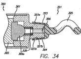
図29に示すように、ハンドセットは、主本体部分359と、ハウジング361と、電源363と、光源365と、機器装着部364と、オブトラトール即ちクリアリングデバイス321(以下に更に詳細に説明する)とを含む。好ましくは、光源365はLED光源365aであり、電源363は、ハウジング361内に直列に配置された複数の電池を含む。電力を光源に提供するための回路は当該技術分野で周知であり、及び従って、その説明は省略する。好ましい実施形態では、ハンドセット(詳細にはハウジング361)は、全体にチューブ状である。換言すると、必ずしも円形断面を備えていなくてもよく、正方形形状や楕円形形状等の他の形状であってもよい。
As shown in FIG. 29, the handset includes a
好ましい実施形態では、ハンドセット360内には電池363が設けられている。この実施形態では、使用前に電池が消耗しないように回路を開いておく構成が使用される。例えば、薄い紙片等(本明細書中、リップコード又は開路器369)を二つの電池363間に挿入して開路状態を保持する。次いで、適当な時期にこれを取り除き、電池間を電気的に連通し、回路を閉じ、光源365で照明を行う。図29に示すように、ハウジングには、好ましくは、リップコード369を通すスロット371が設けられている。
In the preferred embodiment, a
使用では、外科医がハンドセット360を使用する準備ができたとき、リップコードを引っ張ってLED365aに電力を提供する。その後、所定時間に亘って(例えば、電池がなくなるまで)作動する。ハンドセット360は、再使用可能であるように形成されていてもよいということは理解されよう。例えば、壁に設けられた代表的なコンセントにプラグを差し込んで交流電力で作動するように設計されていてもよいということは当業者には理解されよう。
In use, when the surgeon is ready to use
好ましい実施形態では電源及び光源は、ハンドセット360の外部からシールしてある。これは、作用領域の殺菌を助け、汚染が生じないようにする。
In the preferred embodiment, the power source and light source are sealed from the exterior of the
別の好ましい実施形態では、電池を賦活し、光源を点灯するため、リップコードを使用する代わりにラッチスイッチ機構を使用する。ラッチスイッチ機構のスイッチを入れるための全ての方法が本発明の範囲に含まれる。例えば、図46及び図47に示すように、ハンドセット360は、捩じったり押したりすることによってデバイスのスイッチを入れることができるテールコーン即ちボタン337を含んでいてもよい。又は、スイッチを雌レシーバ366の内部に配置してもよい。この実施形態ではクリアリングデバイス321、クリアリングデバイスアッセンブリ341、又は通しロッド300(以下に説明する)をレシーバ366に挿入したとき、スイッチが入り、電池及びLEDがエネルギー供給される。例えば、図46においてO−リング335と隣接して配置されたリングを磁気作動式スイッチに連結してもよい。
In another preferred embodiment, a latch switch mechanism is used instead of using a lip cord to activate the battery and turn on the light source. All methods for switching on the latch switch mechanism are within the scope of the present invention. For example, as shown in FIGS. 46 and 47, the
機器装着部364及びクリアリングデバイス321を以下に更に詳細に説明する。
The
図8乃至図11は、皮膚ポート80を示す。代表的な手順では、複数の皮膚ポート80を使用する。好ましい実施形態では、皮膚ポート80は使い捨ての透明プラスチックスリーブであり、ランセット40によって形成したアクセス箇所14に一つずつ挿入される。
8 through 11 show the
一般的には、皮膚ポート80はフランジ即ちカフ82を含み、ここからチューブ84が延びている。チューブ即ちスリーブ84の一端を、フランジ82が皮膚の外面に載るまで皮膚の穿刺穴14に挿入する。フランジ82及びチューブ84が協働し、皮膚の下の領域へのアクセスを提供するトンネル86を形成する。好ましくは、ポート80は、着色した透明プラスチックで形成される。しかしながら、ポート80はこの他の材料で形成されていてもよく、透明である必要はなく、着色してなくてもよい。
Generally,
好ましい実施形態では、ハンドセット60又は360を使用し、各ポート80を個々のアクセス箇所14を通して展開する。好ましくは、皮膚ポート80はキットで提供されるが、これは本発明を制限するものではない。ハンドセット60の設計により、皮膚ポート80と手早く相互係止し、キットから取り出すことができる。皮膚ポート80をアクセス箇所14内に展開できるようにハンドセット60と皮膚ポート80との相互係止を可能にする任意の設計が本発明の範囲内に含まれるということは理解されよう。
In the preferred embodiment, a
好ましい実施形態では、ポート80を雄コネクタ68にスナップ嵌めする。例えば、図8に示すように、雄コネクタ68には、全周に亘って延びる押縁68aが設けられている。この押縁は、フランジ82の窪み状リング82aと協働する。押縁68a及び窪み状リング82aは、ポート80をハンドセット60の雄コネクタ68と係合させるスナップ嵌めを提供する。他のスナップ嵌め構成が考えられる。
In the preferred embodiment,
次いで、チューブ84をアクセス箇所14に挿入する。図8乃至図11に示すように、好ましい実施形態では、皮膚ポート80は、チューブ84の外面に設けられたねじ山88及び折り畳み機構90を含むアンカーシステムを備えている。折り畳み機構90は、好ましくは、内ねじを備えたリング90bに取り付けられた一対の折り畳み部材90aを含むリング90bは、チューブ84上でねじ山88に従って上下に移動する。
The
図8に示すように、雄コネクタ68の端部には、ポート80の歯82bと相互係止するようになった複数の歯68bが設けられている。ポート80が機器装着部64と係合したとき、歯68bが歯82bと係合し噛み合う。チューブ84をアクセス箇所14に挿入した後、折り畳み機構90を展開するため、ハンドセット60を時計廻り方向に廻す(ポート80は、反時計廻り方向に展開するように設計されていてもよい)歯68bと82bとの係合により、チューブ84がハンドセット60とともにフランジ82内で回転し、これによって内ねじを備えたリング90bをねじ山88に沿って上方に移動する。図11でわかるように、折り畳み部材90aは、折り目90cを含む。ねじ山を備えたリング90bが上方に移動するとき、折り畳み部材90aが図10に示すように折り畳まれ、これによってアンカーを提供し、ポート80がアクセス箇所14から引き抜かれないようにする。折り畳み部材90aは、折り畳まれていない状態(図9参照)及び折り畳まれた状態(図10参照)で配置できる。
As shown in FIG. 8, a plurality of teeth 68 b adapted to interlock with the
好ましい実施形態では、フランジ82は、このフランジから下方に延びる複数のスパイク94を含む。これらのスパイクは、皮膚に食い込んでポート80を所定位置に固定するのを補助する。
In the preferred embodiment, the
ポート80の配置中、ハンドセット60に光ファイバコアが設けられており、皮膚ポート80が透明であるため、挿入時に、光を当てたプローブチップを皮膚を通して見ることにより、皮膚ポート80を安全に展開できる。アンカーシステムにより、ハンドセット60を引っ込めるとき、押縁68aが窪み状リング82aから引き出され、皮膚ポート80が所定位置に固定される。別の実施形態では、外科医は、機器装着部64からのポート80の分離を親指を使用して補助できる。
During placement of the
好ましくは、ポート80は使い捨てであり、一回の手術にしか使用されない。これらのポートは、術野へのアクセスを得るために使用されるに過ぎないということは理解されよう。従って、使用されるポートの種類は、本発明を限定するものではない。皮膚を通したアクセスを提供する任意の種類のポートが本発明の範囲に含まれる。皮膚を通して光が見えることにより、外科医に立体的フィードバックを提供する。
Preferably,
図12に示すように、変形例では、ポート96は、フランジ82に関して直角以外の角度で配向されたチューブ84を備えていてもよい。例えば、チューブ84は、フランジに関して45°の角度で配向されていてもよい。
As shown in FIG. 12, in a variation, the port 96 may include a
図13乃至図17は、通しデバイス100の好ましい実施形態を示す。好ましい実施形態では、通しデバイス100は、ステンレス鋼製の可鍛性のロッド又はチューブであり、アイレット102が形成されており、丸みのある尖っていないチップ(先端部材)104が設けられている。好ましくは、通しデバイス100は、チップ104を照明できる光ガイド(これは、光ファイバコアであってもよい)を含む。この実施形態では、チップ104は、好ましくは、プラスチック等の半透明材料で形成されており、通しデバイス100の主本体に取り付けられる。通しデバイス100の端部108は、ハンドセット60又は360の機器装着部64又は364に装着されるように設計されている。好ましい実施形態では、端部108は、雌コネクタ66と係合するためにねじ山が設けられているが、端部108は、多くの様々な方法で機器装着部64に装着できるということは理解されよう。例えば、機器装着部64は、通しデバイス100を所定の場所に保持する止めねじを含んでいてもよいし、何らかの種類のスナップ嵌め又はプレス嵌めを提供してもよい。別の実施形態では、ドリルに設けられているのと同様のクランプ又はチャックを使用してもよい。更に、端部108には内ねじが設けられていてもよく、外ねじを備えた器具装着部に装着してもよい。器具装着部64により、通しデバイス100の連結及び取り外しを手早く行うことができる。
13-17 illustrate a preferred embodiment of the
ハンドセット60が光ファイバ光ポート62を含む実施形態では、端部108(開口部108aを含む)を器具装着部64に装着することにより、光を通しデバイス100のチップ104まで透過させることができる。別の実施形態では、この他の種類の照明装置を使用してもよい。例えば、LED、白熱灯、蛍光灯、及び他の光源を使用してもよい。
In embodiments where the
アイレット102を使用して縫合材150を固定するということは理解されよう。アイレット102は、通しデバイス100に沿った任意の位置に配置できる。
It will be appreciated that the
使用では、通しデバイス100(及び縫合材150)を様々な皮膚ポート80に挿入し、支持マトリックス200を形成する。
In use, threading device 100 (and suture 150) is inserted into
図36乃至図45は、通しデバイス即ちロッド300の別の実施形態を示す。このデバイス300には、その端部間のほぼ中間の点にアイレット302又は溝303(本明細書中、縫合材結索位置と呼ぶ)が設けられている。図52に示すように、好ましい実施形態では、縫合材150を通しデバイス300の周囲に結び、溝303に入れる。溝303は、好ましくは、デバイス300の外側に全周に亘って形成されている。しかしながら、別の実施形態では、溝は、デバイス300の周囲の一部に亘ってしか設けられていない。デバイス300には、更に、結び目150cを受け入れる凹所305が設けられていてもよい。これにより、結び目150cの輪郭を小さくし、通しデバイス300を使用するときに結び目150cがどこか(人体、皮膚、縫合材、等)に捕まることがないようにするのを補助する。
FIGS. 36-45 show another embodiment of a threading device or
図38に示すように、好ましい実施形態では、通しデバイス300は両端部即ち両チップ(両先端部材)304と、チューブ307と、端キャップ304aと、光ガイド306とを含む。別の実施形態では、通しデバイス300は中実である。更に別の実施形態では、チップ及び光ガイドは一体であってもよく、又はチップを省略してもよい。通しデバイス300は、照明性能を持たない中実の金属であってもよく、又はデバイス全体が光るように、及び/又はデバイスが比較的可撓性であり、容易に且つ比較的安価に製造されるように、半透明材料又は透光性材料(プラスチック等)で形成された中実体(又は複数の構成要素)で形成されていてもよい。好ましい実施形態では、通しデバイス300の端部又はチップは、先が尖っていないということは理解されよう。本明細書中で使用されているように、先が尖っていないというのは、端部が、十分な力(以下に説明する手順で代表的に使用される以上の力)が加わっていない場合に、皮膚又は患者の解剖学的構造の任意の他の部分を穿刺しないということを意味する。当業者に理解されるように、代表的な縫合材ニードルは、これに非常に小さい圧力又は力を加えることによって皮膚を穿刺する。本発明の通しデバイス300の先が尖っていない(平らであるか或いは凸状の)端部は、以下に説明するように使用したとき、皮膚を穿刺しない。しかしながら、別の実施形態では、これらの端部が尖っていてもよい。
As shown in FIG. 38, in a preferred embodiment,
アイレットを備えた実施形態では、アイレット302は、このアイレットを通して結び目150cを結ぶとき、結び目が凹所部分(図示していないが、凹所305と同様である)に受け入れられるように形成されていてもよい。
In an embodiment with an eyelet, the
更に別の実施形態では、縫合材150及び通しデバイス300を一つのユニットとして形成してもよい。換言すると、縫合材150が通しデバイス300に永久的に取り付けられており、これらの二つを一つのユニットとして外科医に提供できる。
In yet another embodiment, the
好ましくは、通しデバイス300は可鍛性である。例えば、チューブ307は、ステンレス鋼、チタニウム、又は他の金属で形成されていてもよく、光ガイド306は、プラスチック(例えば、アクリル樹脂、スチレン、ポリカーボネート、等)又はガラスで形成されていてもよい。
Preferably,
別の好ましい実施形態では、通しデバイス300を更に曲がり易く形成する(アクセス箇所14への挿入を更に容易にする)ため、チューブ307は、両端部から溝303、アイレット302、又は縫合材結索位置まで傾斜(テーパ)していてもよい(又は、中実ロッドの場合には、デバイス300全体が傾斜していてもよい)(図37及び図39参照)。別の実施形態では、図41及び図49に最も良く示すように、ロッドは、溝303の左側の第1位置333aから第1端部に向かって傾斜しており、ロッドは溝303の右側の第2位置から第2端部に向かって傾斜している。従って、ロッドは第1及び第2の端部の直径が第1及び第2の位置よりも小さい。図41及び図42に示すように、第1及び第2の位置333aと333bとの間の領域は、溝303を除いて直径が一定である。これにより、応力がロッド300の中心に集中しないようにし、ロッドが使用中に破損しないようにする。第1及び第2の位置333a及び333bは、ロッド300の長さに沿ったどこに配置されていてもよいということは理解されよう。
In another preferred embodiment, to form the
図36に示すように、一つの好ましい実施形態では、通しデバイス300は円形ではない。例えば、六角形であってもよい。この実施形態では、ハンドセット60又は360の器具装着部364の雌レシーバ366は、対応する形状を有する。これによって、装着時に通しデバイス300が回転しないようにする。別の実施形態では、通しデバイス300の端部だけが多角形をなしている。通しデバイス300をキー止めし、回転しないようにする方法は、本発明の範囲に含まれるということは理解されよう。更に、通しデバイス300が雌レシーバ366から引き出されないようにするのを補助するため、器具装着部には、この装着部に挿入されたデバイスに対して摩擦嵌めを提供する弾性O−リング335が設けられていてもよい。
As shown in FIG. 36, in one preferred embodiment,
図38に示すように、チューブ307は中空であり、光ガイド306がこれに通してある。一つの好ましい実施形態では、チューブ307の端部304には、好ましくは、端キャップ304が装着してある。これらの端キャップ304aは、好ましくは中空であり、透明プラスチックで形成されており、好ましくは、チューブ307にプレス嵌めで受け入れられるフランジ304bを含む。キャップ304aは、更に、チューブ307の端部にねじ込んでもよいし、接着してもよい。好ましい実施形態では、端キャップ304aは弾丸形状であり、全反射を提供する。
As shown in FIG. 38, the
図41、図42、及び図43に示すように、別の好ましい実施形態では、チューブ307は円形であり、光ガイド306はチューブ307の端部304と面一であり、上文中に説明した凹所がなくしてある。この実施形態は、更に、上文中に説明した傾斜(テーパ)位置333a及び333bを含む。しかしながら、これらの位置333a及び333bをなくしてもよく、従って、溝303を除いて直径が一定のチューブ307を提供してもよい。この実施形態では、キャップ304aは省略される。光ガイド306をチューブ307に固定するため、光ガイド306とチューブ307の内径との間の空間を接着剤で充填し、光ガイド306を注封してもよい。光ガイド306全体又は端部だけを注封してもよいということは理解されよう。この実施形態では、ロッド300の端部304を研削し、研磨し、バフ仕上げを施して光の透過率を向上し、チューブ307の端部及び光ガイド306を図43に示すように面一にする。端部304は平らであってもよいし凸状であってもよい。
In another preferred embodiment, as shown in FIGS. 41, 42, and 43, the
当業者には理解されるように、好ましい実施形態では、光ガイド306での全反射を向上するため、光ガイド306にクラッド(被覆)が施してあってもよい。プラスチック製の光ガイドを使用する場合には、光ガイド306の外側にクラッドを施してもよい。ガラス製の光ガイドを使用する場合には、当該技術分野で既知のように、ガラス製光ガイドの延伸前にガラスビレットにクラッドを施す。クラッドを使用することは、本発明を限定するものではないが、これが使用された場合には、注封コンパウンドは光の透過率を減損し、効率を低下する。
As will be appreciated by those skilled in the art, in a preferred embodiment, the
通しデバイス300をハンドセット360に装着したとき、光は、ロッド300の一端304を透過し、光ガイド306を通過し、他端304から出る。好ましい実施形態では、雌レシーバ366の底部は端部304と相補的形状を有し、これによって光を効率的に透過する。
When the
好ましい実施形態では、高効率白色LEDを使用する。この実施形態では、照明デバイス360は、電圧を高効率白色LED用の所望レベルまでブーストするため、DC/DCコンバータを備えていてもよい。
In a preferred embodiment, a high efficiency white LED is used. In this embodiment, the
LEDが発した光を集中させ、狭い焦点角度で放射するのが望ましいということは当業者には理解されよう。好ましい実施形態では、光ガイド306の開口数(numerical aperture)を、LEDから発せられる光とできるだけ一致させる。これは、光の透過率の効率を最大にするのを補助する。
Those skilled in the art will appreciate that it is desirable to concentrate the light emitted by the LED and emit it at a narrow focal angle. In a preferred embodiment, the numerical aperture of the
図40に示すように、別の実施形態では、通しデバイス300は電源391及び光源393を内蔵している。例示の実施形態では、電源391及び光源393(例えばLED)は導線395によって接続されている。この実施形態では、ハンドセットは省略してある。例えば、通しデバイス300は、LED等を各端に備えていてもよい。
As shown in FIG. 40, in another embodiment, the
別の実施形態では、ハンドセットは通しデバイスを往復動させることにより、通しデバイスを皮下に通すのを補助する。往復動作用により、通しデバイスを容易に脂肪組織に通すことができ、かくして、血管、神経構造、及び他の皮下の靱帯に対する付随的損傷を少なくする。この実施形態は、モツッアリーに付与された米国特許第6,139,518号に記載のカニューレを往復動するためのデバイスと同様である。出典を明示することにより、この出願に開示された全ての内容は本明細書の開示の一部とされる。この実施形態では、ハンドセットには、通しデバイスを手術中に前後に往復動させるように動力が加えられる。通しデバイスは、往復動部材に取り付けられた、往復動部材と一体に形成された、又は往復動部材に選択的に接合できるコネクタによってハンドルに連結されていてもよい。別の実施形態では、ハンドセットは通しデバイスを超音波で往復動させ、又は振動させる。 In another embodiment, the handset assists in passing the threading device subcutaneously by reciprocating the threading device. Due to the reciprocating motion, the threading device can be easily passed through adipose tissue, thus reducing collateral damage to blood vessels, nerve structures, and other subcutaneous ligaments. This embodiment is similar to the device for reciprocating the cannula described in US Pat. No. 6,139,518 to Mozzarley. By specifying the source, all contents disclosed in this application are made part of the disclosure of this specification. In this embodiment, the handset is powered to reciprocate the threading device back and forth during surgery. The threading device may be connected to the handle by a connector attached to the reciprocating member, integrally formed with the reciprocating member, or selectively connectable to the reciprocating member. In another embodiment, the handset causes the threading device to reciprocate or vibrate with ultrasound.
図33乃至図35bは、クリアリングデバイス321の様々な実施形態を示す。クリアリングデバイス321は、穿刺箇所即ちアクセス箇所を探り、靱帯及び他の障害物を避けるための先が尖っていない器具である。一般的には、クリアリングデバイス321は、ネック(装着部分とも呼ぶ)323及びクリアリング部分325を含む。クリアリング部分325は、好ましくは、通しロッド300とほぼ同じ直径であり、これらは両方ともアクセス箇所に嵌着する。
FIGS. 33-35b show various embodiments of the
図33及び図34に示すように、一つの好ましい実施形態ではクリアリング部分325は螺旋形形状である。これにより、外科医はクリアリング部分325をアクセス箇所14に挿入し、デバイスを回転させることによってアクセス箇所の下の力を走査できる(クリアリングデバイス321の使用を示す図である図51を参照されたい)。
As shown in FIGS. 33 and 34, in one preferred embodiment, the
好ましい実施形態では、クリアリングデバイス321をハンドセット360にスナップ嵌めする。これを行うため、ネック323及び器具装着部364は、図34に最も良く示すように、対応する突出部327a及び窪み327bを含む。クリアリングデバイス321は、好ましくはプラスチック製であり、これによりスナップ嵌め構成のための可撓性を提供し、更に、クリアリングデバイス321を光透過性にできる。使用では、器具装着部364から光が発せられ、この光がクリアリングデバイス321を透過する。別の実施形態では、クリアリングデバイス321のチップだけが光を通し、残りの部分は不透明である。これは、光をチップに差し向けるのを補助する。別の実施形態では、クリアリングデバイス321は金属製であってもよい。
In the preferred embodiment, the
クリアリングデバイス321は、ハンドセット360に他の方法で取り外し自在に取り付けられていてもよい。例えば、ネック323の一部がハンドセット360のスロットに受け入れられ(又はこれとは逆の構成をなし)、次いでクリアリングデバイスを回転し、所定位置に係止することを使用してもよい。更に、図32に示すように、ねじ山を備えた構成329が本発明の範囲に含まれる。クリアリングデバイス321は、ハンドセット60に装着されるように設計されていてもよい。
The
図46及び図47を参照すると、これらの図にはクリアリングデバイス321の別の実施形態が示してある。この実施形態では、クリアリングデバイス321は、図46に示すように、雌レシーバ366に装着したロッドであってもよい。この実施形態では、クリアリングデバイス321は、ネック(又は装着部分)323及びクリアリング部分325を含む。ネック323は、雌レシーバ366に挿入したときに回転しないようにキー止め(以下に説明する通しデバイスと同様に)されていてもよい。
Referring to FIGS. 46 and 47, there are shown another embodiment of the
図35A及び図35Bは、湾曲クリアリング部分325a及び直線状クリアリング部分325bを持つクリアリングデバイスの別の実施形態を示す。これらのクリアリング部分は、雌レシーバ366に受け入れられたクリアリングデバイスにも含まれていてもよい。
35A and 35B show another embodiment of a clearing device having a curved clearing portion 325a and a
図46乃至図49を参照すると、これらの図には、ハンドセット360の別の実施形態が示してある。ハンドセット360は、上文中に説明したのとほぼ同じである。これらの図に示すように、器具装着部は、ねじ山329及び円形の雌レシーバ366を含む。ハンドセット360は、更に、上文中に説明したように、テールコーン337を備えていてもよい。テールコーン337は、クリアリングデバイスを回転するときに外科医が掴むことができるようにするものを提供するに過ぎず、又は上文中に説明したように光源をエネルギー供給するためのラッチスイッチを作動するように設計できる。
Referring to FIGS. 46-49, there are shown another embodiment of a
この実施形態では、デバイスは、更に、器具装着部364に螺着できるノーズコーン339を含む。ノーズコーン339は、好ましくは、グリップ窪み339aを含み、ノーズコーン339を器具装着部364に螺着したときに雌レシーバ366と軸線方向で整合する軸線方向開口部339cが形成されている。ノーズコーン339は、ハンドセット360を使用する場合に外科医に対してグリップを提供する。これにより、外科医は、ハンドセットを、ペンを持つのと同様に保持できる。
In this embodiment, the device further includes a
図46に示すように(一般的には上文中に説明したように)、クリアリングデバイス321は、雌レシーバ366に嵌着するネック323を含む。このネックからクリアリング部分325が延びている。図47に示すように、別の好ましい実施形態では、ノーズコーン及びクリアリングデバイスをユニットとして形成でき、これによってクリアリングデバイスアッセンブリ341を形成する。この実施形態では、ネック323を雌レシーバ366に挿入すると同時にノーズコーン339を器具装着部364に螺着する。O−リング335は、ネック323を雌レシーバ366内に固定するのを補助する。この実施形態では、クリアリング部分325は、ネックの長さ方向軸線に対してほぼ垂直な平面を形成する湾曲経路内を延びる。
As shown in FIG. 46 (generally as described above), the
図47に示すように、クリアリングデバイスアッセンブリ341は、チップを照光するためにこのアッセンブリを通って延びる光ガイド306を含んでいてもよい。しかしながら、本発明はこれに限定されない。
As shown in FIG. 47, the clearing device assembly 341 may include a
クリアリングデバイスアッセンブリ341を使用する手術手順では、好ましくは、図48に示すように、通しロッド300を固定するため、別体のノーズコーン339bを使用する。使用では、クリアリングデバイスアッセンブリ341を使用してアクセス箇所の周囲の領域をクリアした後、クリアリングデバイスアッセンブリ341を器具装着部364からねじって外し、次いでノーズコーン339bを螺着する。ノーズコーン339b内には、図48に示すように、通しロッド300を開口部339c及び雌レシーバ366に挿入するときに通しロッド300を固定するのを補助するためのO−リング335が設けられている。別の実施形態では、ノーズコーン339bを省略してもよい。更に別の実施形態では、ノーズコーン339bは、通しロッドを引き外すのが困難であるように通しロッドを締め付けるための手段を備えていてもよい。例えば、ノーズコーン339bは、止めねじ、チャック、内ねじ等を備えていてもよい。
In a surgical procedure using the clearing device assembly 341, a
図48及び図49に示すように、別の好ましい実施形態では通しロッド300には、固定チャンネル343が全周に亘って形成されていてもよい。ノーズコーン339b又は雌レシーバ366に挿入したとき、チャンネル343の一つがO−リング335を受け入れ、通しロッド300をその中に固定するのを補助する。これらのチャンネルは、以下に説明するように通しロッドが可逆的であるため、両端の近くに配置される。別の実施形態では、器具装着部364のノーズコーン339bは、O−リングの代わりに、チャンネル343に受け入れられる金属製リング345を備えていてもよい(図50参照)。この金属製リングは、O−リングよりも強いスナップ嵌め構成を提供する。
As shown in FIGS. 48 and 49, in another preferred embodiment, a fixed
通しロッド300の長さは、実行される手順の種類(及び患者の解剖学的構造の大きさ)に応じて変化するということは理解されよう。通しロッド300は、この通しロッド300が皮下を通過するとき、一端が出口アクセス箇所から出るときに他端が入口アクセス箇所14の外に延びているのに十分な長さを備えているということが重要である。例えば、経皮的トランポリン広頚筋形成術では、通しロッド300の長さは、約22.86cm(約9インチ)であってもよい。図53を参照すると、これにより通しロッド300の一端がアクセス箇所14bの外に延びている状態で、他端がアクセス箇所14cの外に延びている。MACSリフトでは、通しロッド300はこれ程長くなくてもよい。添付図面に示す通しデバイス100及び300は縮尺通りではないということは理解されるべきである。
It will be appreciated that the length of threading
図57及び図58を参照すると、他の実施形態では、通しロッドは湾曲していてもよいし曲がっていてもよい。例えば、図57に示すように、端部304は様々な方向に湾曲していてもよい。この種の通しロッド300は、中実であってもよいし、その内部に光ガイドが設けられていてもよい。端部は、尖っていてもよいし尖っていなくてもよい。端部が尖った実施形態では、端部304を通して光を伝達するのが困難であり、そのため、開口部347をチューブ307に形成し、端部304から間隔が隔てられた点から光を放射できるようにしてもよい。通しロッド300は、腹部の手術で有用であり、デバイスの強度を向上するため、上述の実施形態よりも太く且つ曲がり難くてもよい。図58に示すように、別の実施形態では通しロッド300bの端部は同じ方向に湾曲していてもよい。
Referring to FIGS. 57 and 58, in other embodiments, the threading rod may be curved or bent. For example, as shown in FIG. 57, the
次に、通しデバイス100を使用する支持マトリックス200の例示の構造を説明する。例えば、図15に示すように、縫合材150の第1端部をアイレット102に連結した後、外科医がハンドセット60を掴み、通しデバイスを第1皮膚ポート80aに挿入する。通しデバイス100の照光チップ104が術野を照らし、これが皮膚を通して見えることにより、外科医は支持マトリックス200の適正な配置及びチップ104の位置を確認する。上文中に説明したように、好ましい実施形態では、ポート80は、通しデバイス100の通過を補助するため、透明である。換言すると、通しデバイス100のチップ104がポート80に近づくとき、このポートが照らされるのである。
Next, an exemplary structure of the
通しデバイス100は、好ましくは、デバイスが挿入された側とは反対側で顎に設けられた第2皮膚ポート80bを通ってチップ104が出るように、顎線の一方の側から他方の側まで通すことができるのに十分に長い。この時点で、外科医はチップ104を掴み、縫合材150を頚の下の領域を通して引っ張る。次いで、通しデバイス100をハンドセット60から外し、これにより、図16に示すように、通しデバイス100及び縫合材150を第2皮膚ポート80bを通して引っ張ることができる。
The
次いで、通しデバイス100の方向を変え、ハンドセット60に再連結した後、第2皮膚ポート80bに再び挿入し、これを反対側まで皮下に通し、第3皮膚ポート80cを通して出す。通しデバイス100をハンドセット60から再び外し、通しデバイス100及び縫合材150を第3皮膚ポート80cを通して引っ張った後、再連結する。
The
次に、通しデバイス100の方向を変え、ハンドセット60に再連結した後、第3皮膚ポート80cに再び挿入し、これを反対側まで皮下に通し、第4皮膚ポート80dを通して出す。この時点で、通しデバイス100をハンドセット60から再び外し、通しデバイス100及び縫合材150を第4皮膚ポート80dを通して引っ張った後、再連結する。
Next, the
次いで、通しデバイス100の方向を変え、ハンドセット60に再連結した後、第4皮膚ポート80dに再び挿入し、これを反対側まで皮下に通し、第5皮膚ポート80eを通して出す。この時点で、通しデバイス100をハンドセット60から再び外し、通しデバイス100及び縫合材150を第5皮膚ポート80eを通して引っ張った後、再連結する。
The
次に、通しデバイス100の方向を変え、ハンドセット60に再連結した後、第5皮膚ポート80eに再び挿入し、これを中線おとがい下アクセス箇所まで皮下に通す。この箇所は、好ましくは、ねじ山を備えた皮膚ポート120を含む(以下に更に詳細に説明する)。通しデバイス100及び縫合材150の第1端部をねじ山を備えた皮膚ポート120を通して引っ張り、通しデバイスをハンドセット60から外す。次いで、通しデバイス100から縫合材150の第1端部150aを切断し、及び/又は通しデバイスに結索した状態を解く。
Next, after changing the direction of the
次に、第1皮膚ポート80aから延びる縫合材150の第2端部(即ち先端)150bを通しデバイス100のアイレット102に固定し、通しデバイス100をハンドセット60に連結する。外科医がハンドセット60を掴み、通しデバイスを第1皮膚ポート80aに挿入し、これを反対側まで皮下に通し、第6皮膚ポート80fを通して出す。この時点で、通しデバイス100をハンドセット60から再び外し、通しデバイス100及び縫合材150を第6皮膚ポート80fを通して引っ張った後、再連結する。
Next, the second end (or tip) 150b of the
次に、通しデバイス100の方向を変え、ハンドセット60に再連結した後、第6皮膚ポート80fに再び挿入し、これを反対側まで皮下に通し、第7皮膚ポート80gを通して出す。この時点で、通しデバイス100をハンドセット60から再び外し、通しデバイス100及び縫合材150を第7皮膚ポート80gを通して引っ張った後、再連結する。
Next, the
次いで、通しデバイス100の方向を変え、ハンドセット60に再連結した後、第7皮膚ポート80gに再び挿入し、これを反対側まで皮下に通し、第8皮膚ポート80hを通して出す。この時点で、通しデバイス100をハンドセット60から再び外し、通しデバイス100及び縫合材150を第8皮膚ポート80hを通して引っ張った後、再連結する。
The
次に、通しデバイス100の方向を変え、ハンドセット60に再連結した後、第8皮膚ポート80hに再び挿入し、これを中線おとがい下アクセス箇所にあるねじ山を備えた皮膚ポート120まで皮下に通す。ねじ山を備えた皮膚ポート120を通して通しデバイス100及び縫合材150の第2端部150bを引っ張り、通しデバイスをハンドセット60から外す。
Next, the
当業者に理解されるように、皮膚ポート80に設けられたチューブ84は、このチューブを通して通しデバイス100を挿入したとき、上文中に説明した手順中、顔面保持靱帯(facial retaining ligament) を取り囲むことにより縫合材150それ自体が固定されるのに十分に長い。好ましくは、通しデバイス100及び縫合材150をポート80に通す度毎に、縫合材は顔面保持靱帯に固定され、これによってアンカー即ち転向点を形成する。
As will be appreciated by those skilled in the art, the
上文中に説明したアクセス箇所14、ポート80、及び/又は通過等の数は単なる例示であって、ここに説明する手順では、特定の患者が必要とする任意の数を使用できるということは理解されよう。
It should be understood that the numbers of
通しデバイス100のチップ104から皮膚を通して光が透過することにより、支持マトリックス200をジグザグに通して形成するとき、外科医がチップ104の位置を確認できるようにするフィードバックを提供する。このフィードバックを提供することにより、個々のストランドの各々を、支持を必要とする領域に対して配置できる。これにより、縫合材ストランド150を筋肉と隣接して、皮膚層及び脂肪層よりも深く配置できる。
Transmission of light through the skin from the
好ましくは、各ポート80において、フランジ82と関連したチューブ84の端部には面取りを施した即ち傾斜(テーパ)した縁部84aが設けられており、これにより、通しデバイス100のチップ104が、挿入中にトンネル86の内側に捕捉されないようにする。
Preferably, at each
別の実施形態では、縫合材150の両端に各々連結された二つの通しデバイス100を使用できる。この実施形態では、縫合材150の第2端部を皮膚に通す前に第1通しデバイス100を縫合材150の端部から外す必要がない。更に別の実施形態では、縫合材150は、両端150a及び150bに二つの使い捨ての通しデバイス100が設けられたキットで提供できる。マトリックス200の形成後、通しデバイス100を縫合材150から切断し、次いで縫合材を結索する。
In another embodiment, two
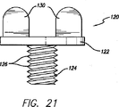
図19乃至図23は、中線おとがい下アクセス箇所に対して使用するためのねじ山を備えた皮膚ポート120を示す。ねじ山を備えた皮膚ポート120は、上文中に説明した皮膚ポート80と同時に挿入される。しかしながら、本発明は、これにより制限されるものではない。ポート120はフランジ122を含み、このフランジからチューブ124が延びている。チューブ124には、好ましくは、ねじ山126が設けられている。図22に示すように、チューブ124及びフランジ122が協働し、貫通トンネル128を形成する。好ましい実施形態では、フランジ122のトンネル128の部分には、面取りを施した即ち傾斜(テーパ)した縁部128aが設けられている。
FIGS. 19-23 show a
好ましい実施形態では、ポート120は、フランジ122から上方に延びる一対のハンドル部分130を含む。これらのハンドル部分は、外科医がポート120を中線おとがい下アクセス箇所に入れるのを補助する。しかしながら、ハンドル部分130は本発明を制限するものではなく、省略してもよい。皮膚を通したアクセスを提供する任意の皮膚ポートが本発明の範囲に含まれるということは理解されよう。例えば、中線おとがい下アクセス箇所で皮膚ポート80等を使用してもよい。別の実施形態では、ポート120をアクセス箇所14で使用してもよい。好ましい実施形態では、通しデバイス100の通過を補助するため、ポート120は透明である。換言すると、通しデバイス100のチップ104がポート120に近づくと光が透過する。
In the preferred embodiment, the
使用時に、チューブ124を中線おとがい下アクセス箇所に挿入する。ハンドル部分130を掴み、フランジ122の底面が皮膚の外面に載止するまでねじ山126が皮膚にねじ込まれるまでポート120を回す。
In use, the
別の実施形態では、上文中に説明した皮膚ポート80と同様であるが幾分変更したポートを中線アクセスに使用してもよい。この実施形態では、フランジの内側にはねじ山が設けられており、これがチューブの外側に設けられたねじ山と係合する。折り畳み部材の先端は、内ねじが設けられていないリングに連結されている。このリングにより、チューブを折り畳み部材の中で回転させることができるが、(内ねじが設けられていないため)リングがチューブのねじ山に従って上昇することがない。折り畳み部材の反対側の端部がフランジに連結される。
In another embodiment, a port similar to the
この形体では、チューブを回転させたとき(好ましくは、ハンドセット又は外科医の指との係合により)、チューブの外側とフランジの内側との螺合によりチューブを外方に(患者の身体の内部に関して)移動する。この作用により、折り畳み部材を折り目のところで折り畳む。患者に関する使用では、折り畳み位置において、チューブの基端が患者の身体の外側に配置され、先端が、折り畳まれていない位置にある場合よりもフランジに近づくように移動する。 In this configuration, when the tube is rotated (preferably by engagement with the handset or surgeon's finger), the tube is outwardly engaged (with respect to the interior of the patient's body) by screwing the outside of the tube with the inside of the flange. )Moving. By this action, the folding member is folded at the fold. For use with a patient, in the folded position, the proximal end of the tube is placed outside the patient's body and the distal end moves closer to the flange than in the unfolded position.
図18、図19、及び図20を参照し、結び目配置器具140を示し、説明する。図19に示すように、縫合材150の両端150a及び150bを通し、支持マトリックス200を形成した後、縫合材の二つの端部150a及び150bを中線おとがい下アクセス箇所を通して(ポート120を通して)出す。単投結び(single throw knot) 150cを配置し(結び目の種類は本発明を限定するものではないということは理解されよう)、結び目配置器具140を使用して結び目150cを固定する。
A
結び目配置器具140の一端142(ここには、好ましくはねじ山が設けられている)をハンドセット60に装着する。他端144はフォーク状になっている。フォーク状端部144を使用し、結び目150cを、ねじ山を備えた皮膚ポート120のトンネル128を通して皮膚の下に押し込む。好ましい実施形態では、結び目配置器具140は、光ファイバコア152と、結び目150cを配置するときに術野を照らすための光を伝達する開口部152aとを含む。
One end 142 (preferably provided with a thread) of the
結び目150cをねじ山を備えたポート120を通して押した後、ねじ山を備えたポート120をねじってアクセス箇所から外し、ハンドセット60を使用して他の皮膚ポート80を除去する。これを行うため、押縁68aが窪み状リング82aにスナップ嵌めし、歯68b及び82bが互いに係合するように雄コネクタ68をポート80に挿入する。次いで、ハンドセット60を捩じることによってチューブ84を回転し、内ねじが設けられたリング90bをねじ山88上で下方に移動して戻し、折り畳み部材90aを折り畳まれた状態から戻す。別の実施形態では、ポート80を手で取り外してもよい。
After pushing the
外傷を残すことなくポート80及び120を取り外した後、ステリストリップ(steristrip)を所望の通りに配置し、頚部圧迫ガーメントを患者に装着する。例示の支持マトリックス200の最終形体について、図25を参照されたい。
After removing
次に、支持マトリックス200の構造の別の例示の実施形態を説明する。図46乃至図51を参照されたい。この実施形態では、ハンドセット360及び通しデバイス300を使用する。この例では、図51乃至図56に示すように、アクセス箇所14の大部分が下顎下境界の上方にある。通しデバイス300が全体に直線状であり、顎の湾曲に亘って移動する必要があるため、通しロッドの方向を頚部の湾曲に沿って変化させることができるように、顎の下に中間アクセス箇所14を設ける必要がある(これを示す例示のアクセス箇所に参照番号14aが付してある)。外科医は、通しロッドの方向を変えることができるように、患者の顎の下の、又は他の位置の他のアクセス箇所を必要に応じて使用することを選択してもよい。
Next, another exemplary embodiment of the structure of the
図51に示すように、通しデバイスを使用する前に、外科医は、アクセス箇所14と隣接した領域の下の真皮取り付け部をクリアするため、クリアリングデバイス321(又はクリアリングデバイスアッセンブリ341)を使用する。図51乃至図56には示してないけれども、外科医は、通しロッド300の固定を補助し、手術中にハンドセット360の操作を補助するため、ノーズコーン339又は339bを使用してもよい。
As shown in FIG. 51, prior to using the threading device, the surgeon uses the clearing device 321 (or clearing device assembly 341) to clear the dermal attachment below the area adjacent to the
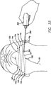
通しデバイス300及び第1縫合材150を最初に入れるため、外科医は、顎先の下にアクセス箇所14aを形成する。ハンドセット360を照明し(例えばリップコードを引っ張ることによって、テールコーン等を捩じったり押したりして光源のスイッチを入れることによって)、通しデバイス300をハンドセット360に挿入する。図52に示すように、アクセス箇所14aを通して通しデバイス300を挿入する。通しデバイス300の照明されたチップ304が術野を照らし、皮膚を通して光り、外科医が支持マトリックス200及びチップ304の位置の適正な配置を決定できるようにする。
To initially place the
次いで、通しロッドを第2アクセス箇所14bを通して出し、縫合材の一部を第2アクセス箇所14bを通して引っ張る。第2アクセス箇所14bを通して十分な縫合材を引っ張り、手順の終了時(以下に説明する)に縫合材を結索できるように丁度十分な縫合材を箇所14aに残す。縫合材の端部が第1アクセス箇所14aに引き込まれないようにするため、止血鉗子等で固定してもよい。縫合材が通しロッド300の中間に結索されているため、外科医は通しロッド全体をアクセス箇所から引き出さなくてもよいということは理解されよう。その代わり、通しロッドの半分を箇所を通して引き出した後、縫合材を引っ張り、外科医はロッドを所望方向に転向でき、次いでロッドをアクセス箇所を通して押し戻す。この動作により、縫合材をアクセス箇所の近くの皮膚の下の靱帯に固定できる。通しロッド300の中央近くに縫合材が取り付けられており、両端が相似であるため、患者の皮膚の下から出す度毎に方向を変える必要はないということは理解されよう。しかしながら、外科医は、通しロッドの方向を所望の通りに変えてもよい。
The threading rod is then extended through the
通しロッドを第2アクセス箇所14bに押し戻す前に、外科医は、図53に示すように通しロッドの端部にハンドセットを配置し、チップ304を照光する。
Prior to pushing the threading rod back to the
次いで、通しロッドを箇所14bから箇所14aに通し、方向を変え、皮下を第3アクセス箇所14cまで通過させる。患者によっては、外科医は、ロッドの方向を箇所14aのところで変えずに、箇所14bから箇所14cまで真っ直ぐに通してもよい。これを第4アクセス箇所14d、第5アクセス箇所14e、及び第6アクセス箇所14fについて繰り返し、最終的には、おとがい下アクセス箇所を通して通しロッドを出す(外科医は、必ずしも各場合に箇所14aに戻る必要はなく、次の箇所に「靴紐を結ぶように」直接延ばしてもよい)。ということは理解されよう。この手順中、一方のチップ304を所望の通りに照光するようにハンドセットを通しロッドに所望の通りに着脱する。次いで、縫合材150を通しロッドから切断する。好ましくは、通しデバイス及び縫合材150をアクセス箇所14に通す度毎に第1縫合材150を隣接した顔面保持靱帯の周囲に通し、これによってアンカー即ち転向点を形成する。
Next, the threading rod is passed from the
図54に示すように、次いで、第2縫合材151を通しロッド300に結索し、この通しロッドを第1アクセス箇所14aに挿入する。次いで、皮下を第7アクセス箇所14gまで通す。第1縫合材150について上文中に説明した手順と同様に、第2縫合材151を第8アクセス箇所14h、第9アクセス箇所14i、第10アクセス箇所14j、及び第11アクセス箇所14kに通し(図55参照)、最終的には中線おとがい下アクセス箇所から出す。次いで、箇所14aの外に出た縫合材150及び151の端部を結索し、これによってマトリックス200を完成する(図56参照)。次いで、結び目150cを箇所14aを通して皮膚の下に押す(例えば、クリアリングデバイス又は通しロッドを使用する)。この時点で、外科医はおとがい下アクセス箇所の外に延びる縫合材150及び151の端部を引っ張ってマトリックス200に所望の張力を加える。これが行われた後、縫合材150及び151の端部を互いに結索し、結び目150cを箇所を通して皮膚の下に押す。
As shown in FIG. 54, the
外科医は、これをハンドセットなしで行うことができるということは理解されよう。外科医によっては、チップを照明するためのハンドセットを使用せずに通しロッドだけを使用しようとする。この場合には、中実の通しデバイス又は電源及び光源を内蔵した通しデバイスを使用できる。更に、通しデバイス300は、他の種類の手術にも使用できるということは理解されよう。例えば、顔面や頚部の皮膚及び/又は身体の他の領域に開口部を形成したり持ち上げたりすることを予め必要とする形成手術で一般的に使用されている縫合材システムの配置に使用してもよい。この例には、本デバイス又はシステムを頚部形成縫合材を配置するのに使用することが含まれ、又はMACSリフト(最小アクセス頭部懸架)で使用できる。これは、2007年3月/4月に刊行された美容整形外科誌第7巻第2号の第188頁乃至第198頁に記載された、パトリックトンナード医学博士及びアレクシスメルパイル医学博士の「MACSリフト短瘢痕皺切除術」に記載されている。出典を明示することにより、この文献に開示された全ての内容は本明細書の開示の一部とされる。この手順では、「財布の紐」縫合材を使用する。縫合材を配置するため、外科医は、代表的に形成される切開部を形成する代わりに通しロッド300を使用してもよい。
It will be appreciated that the surgeon can do this without a handset. Some surgeons attempt to use only a threaded rod without using a handset to illuminate the tip. In this case, a solid threading device or a threading device incorporating a power source and a light source can be used. Further, it will be appreciated that the
頚部形成縫合材は、当該技術分野で既知のように、2005年に刊行された、審美的形成手術第29巻の第341頁乃至第350頁に記載された、ヴィンセントジャンパパ医学博士、イオアニスビツッオース医学博士、オスカーラミレス医学博士、及びマークグラニック医学博士の「頚部若返り再訪用縫合材懸架広頚筋形成術(優れた結果をもたらすための技術的に優れた点)」という文献に記載されている。出典を明示することにより、この文献に開示された全ての内容は本明細書の開示の一部とされる。しかしながら、頚部領域の下の皮膚に大きな切開部を形成し、持ち上げる代わりに、本手順は、耳の後ろに小さな切開部を形成した後、通しロッド300及び必要な転向点(アクセス箇所)を所望の通りに使用して縫合材を皮下で下顎骨の下に通すことによって行ってもよい。
The cervical plasty suture, as known in the art, has been published in 2005, aesthetic plastic surgery volume 29, pages 341-350, Dr. Vincent Jumpapa, MD, Ioannis. Described in the literature by Dr. Bittuose, Dr. Oscar Ramirez, and Dr. Mark Granic, "Suture Suspended Suspended Wide Neck Myoplasty (Technical Superiority to Bring Out Superior Results)" Has been. By specifying the source, all the contents disclosed in this document are made a part of the disclosure of this specification. However, instead of making a large incision in the skin under the cervical region and lifting it up, the procedure makes a small incision behind the ear and then the threading
好ましい実施形態では、手順で使用される縫合材は4.0編成ポリエステル縫合材である。更に好ましい実施形態では、図24に示すように、縫合材設計は、少なくとも一つの光ファイバストランド150dを含み、この光ファイバストランドは、光ファイバでないストランドと編み合わせてある。縫合材150は、当該技術分野で既知のように、所望に応じて、一本、二本、又は三本の光ファイバストランド及び一本又は二本の光ファイバでないストランドで編成される。これにより、縫合材150の配置後に皮下の配置を確認するため、皮膚を通して縫合材150を光らせるのが補助される。光ファイバストランド150dは、結び目配置器具140に光ファイバで光連結されたハンドセット60を結索中に縫合材に近付けるときに光を発する。縫合材に伝達された光により、外科医は、支持マトリックス200を固定したときにこの支持マトリックスの配置を見ることができる。光ファイバでないストランドは、ナイロン、ポリプロピレン、又は他の非吸収性材料等の当該技術分野で既知の任意の材料で形成できる。
In a preferred embodiment, the suture used in the procedure is a 4.0 knitted polyester suture. In a more preferred embodiment, as shown in FIG. 24, the suture design includes at least one
支持マトリックス200の形成中の任意の時点で、ハンドセット60又は360(又は任意の他の光源)を縫合材150の端部150a又は150bの一方に配置することによって縫合材の配置を確認できる。これによって、光ファイバストランド150dに光を通し、縫合材150の配置を確認する。
At any point during the formation of the
縫合材の経路を照らすことにより、外科医は縫合材の位置を確認できる。全体として、縫合材が光ることにより、各転向点の解剖学的移動に関するフィードバックを外科医に提供する。 By illuminating the suture path, the surgeon can determine the location of the suture. Overall, the suture material shines to provide feedback to the surgeon regarding the anatomical movement of each turning point.
光ファイバ縫合材は、本明細書中に説明した技術だけでなく、手術の全ての領域で、又は光結合材料を必要とする他の材料で使用できるということは当業者には理解されよう。別の実施形態では通しデバイスは、直線状の又は湾曲したニードルであってもよい。手術手順中に光エネルギを適用することにより、縫合材の配置及び正確性を確認する。術後に光を適用することにより、外科医は、時間及び老化に関する縫合材配置の変化(進化)を理解できる。 Those skilled in the art will appreciate that fiber optic sutures can be used not only in the techniques described herein, but in all areas of surgery, or other materials that require optical coupling materials. In another embodiment, the threading device may be a straight or curved needle. Applying light energy during the surgical procedure confirms the placement and accuracy of the suture. By applying light post-surgery, the surgeon can understand the changes (evolution) in suture placement with time and aging.
変形例では、上文中に論じた標準的手順で使用されるのと同様の切開部を介して、頚部の皮膚を広頚筋から持ち上げることができ、これにより、外科医は術野を見ることができ、次いで、ポート80及び/又はアクセス箇所14を通して縫合材マトリックスを配置できる。
In a variant, the cervical skin can be lifted from the cervical muscle through an incision similar to that used in the standard procedure discussed above, which allows the surgeon to see the operative field. The suture matrix can then be placed through
上文中に説明した器具は、キットで販売してもよいと考えられる。例えば、テープ10又は310、マーキングペン、ランセット40、ハンドセット60又は360、皮膚ポート80、通しデバイス100又は300、ねじ山を備えた皮膚ポート120、結び目配置器具140、縫合材150又は151、ノーズコーン339、クリアリングデバイス321、クリアリングデバイスアッセンブリ341、又は本明細書中に説明した任意の他の器具を含む器具の全ての組み合わせ又は任意の組み合わせを含むキットを販売できる。
The devices described above may be sold in kits. For example,
上文中に説明した実施形態は、本発明の例示の実施形態である。当業者は、本明細書中に開示した本発明の概念から逸脱することなく、上文中に説明した実施形態を様々に使用でき、発展できる。従って、本発明は、以下の特許請求の範囲のみによって定義されるべきである。
本発明の参考例を以下に記載する。
[例1]
手術を行う方法において、
a)皮膚に複数の開口部を形成する工程と、
b)前記開口部の各々に皮膚ポートを挿入する工程と、
c)前記皮膚ポートを通して縫合材を挿入し、皮膚の下に縫合材マトリックスを形成する工程と、を含む、方法。
[例2]
例1に記載の方法において、
前記手術はネックリフト手術である、方法。
[例3]
例1に記載の方法において、
前記複数の開口部は、第1群及び第2群を含み、前記縫合材マトリックスは、前記第1群の開口部と前記第2群の開口部との間で前記縫合材をジグザグに通すことによって形成される、方法。
[例4]
例3に記載の方法において、更に、
中線アクセス箇所を皮膚に形成する工程を含み、前記中線アクセス箇所は、ほぼ、前記第1群と前記第2群との間に配置される、方法。
[例5]
手術を行う方法において、
a)テープテンプレートを患者の皮膚の一部に置く工程と、
b)複数のアクセス箇所のマークを付ける工程と、
c)中線アクセス箇所を形成するために開口部を形成する工程と、
d)脂肪吸引を行う工程と、
e)前記アクセス箇所のところで皮膚に複数の開口部を形成する工程と、
f)前記開口部の各々に皮膚ポートを挿入する工程と、
g)前記中線アクセス箇所に皮膚ポートを挿入する工程と、
h)縫合材を結索した通しデバイスを提供する工程と、
i)前記通しデバイス及び前記縫合材を少なくとも一つの皮膚ポートを通して挿入し、皮膚の下に縫合材マトリックスを形成する工程と、
j)前記中線アクセス箇所の前記皮膚ポートを通して前記縫合材の端部を引っ張る工程と、
k)前記縫合材の前記端部を結んで結び目にする工程と、
l)前記結び目を前記中線アクセス箇所の前記皮膚ポートを通して皮膚の下に押す工程と、
m)前記アクセス箇所の前記開口部から前記皮膚ポートを取り除く工程と、を含む、方法。
[例6]
手術用キットにおいて、
a.少なくとも一つのテープ部材、
b.ランセット、
c.ハンドセット、
d.複数の皮膚ポート、
e.通しデバイス、
f.ねじ山を備えた皮膚ポート、
g.結び目配置器具、及び
h.縫合材
のうちの少なくとも二つを含む、手術用キット。
[例7]
例6に記載の手術用キットにおいて、前記ハンドセットは、
a.第1及び第2の両端部を持ち、長さ方向軸線を形成する全体にチューブ状の主本体部分と、
b.前記主本体部分の前記第1端部から延びる、全体にチューブ状形状の、ねじ山を備えた雌コネクタを含む器具装着部と、
c.前記主本体部分の前記第2端部から延びる光ポートと、を含む、手術用キット。
[例8]
例7に記載の手術用キットにおいて、前記通しデバイスは、
a.第1及び第2の両端部と、内部と、そこに形成されたアイレットとを含む細長いチューブであって、前記細長いチューブの前記第1端部には鈍チップが取り付けられており、前記第2端部はねじ山を備えたコネクタを含み、前記鈍チップは半透明である、細長いチューブと、
b.前記細長いチューブの前記内部を通って延びる少なくとも一つの光ファイバストランドを含み、前記少なくとも一つの光ファイバストランドがエネルギー供給されたとき、前記半透明チップが照らされる光ファイバコアと、を含む、手術用キット。
[例9]
例8に記載の手術用キットにおいて、前記結び目配置器具は、
a.内部と、各々に開口部が形成された第1及び第2の両端部とを含む細長いチューブであって、前記細長いチューブの前記第1端部はフォーク状であり、前記第2端部はねじ山を備えたコネクタを含む、細長いチューブと、
b.前記細長いチューブの前記内部を通って延びる少なくとも一つの光ファイバストランドを含み、前記少なくとも一つの光ファイバストランドがエネルギー供給されたとき、前記細長いチューブの前記第1端部の前記開口部を通して光が伝達される、光ファイバコアと、を含む、手術用キット。
[例10]
例9に記載の手術用キットにおいて、
前記縫合材は、少なくとも三つのストランドを含む編成縫合材を含み、前記ストランドのうちの少なくとも一つが光ファイバ材料で形成されている、手術用キット。
[例11]
例6に記載の手術用キットにおいて、前記少なくとも一つの皮膚ポートは、
a.長さ方向軸線を形成するフランジと、
b.前記フランジから下方に延びるチューブであって、前記チューブは前記チューブと軸線方向で整合しており、前記フランジ及び前記チューブが協働してそこを貫通するトンネルを形成し、前記チューブは前記フランジ内で回転自在であり、前記チューブは、折り畳み機構及びチューブ外面に形成されたねじ山を含む、手術用キット。
[例12]
手術前に皮膚にマークを付ける方法において、
a)各々に複数の穴が形成された第1及び第2のテープ部材を提供する工程と、
b)前記第1テープ部材を皮膚の一部に配置する工程と、
c)前記第2テープ部材を、前記第1テープ部材が前記第2テープ部材から間隔が隔てられるように、皮膚の一部に配置する工程と、
d)前記第1テープ部材の前記穴のうちの少なくとも一つの穴を通して皮膚にマークを付ける工程と、
e)前記第2テープ部材の前記穴のうちの少なくとも一つの穴を通して皮膚にマークを付ける工程と、
f)前記第1及び第2のテープ部材を皮膚から取り外す工程と、を含む、方法。
[例13]
例12に記載の方法において、
前記第1及び第2のテープ部材の穴は、互いから等間隔に間隔が隔てられている、方法。
[例14]
例13に記載の方法において、
前記第1及び第2のテープ部材の穴は、前記テープの前記長さ方向中心に沿って配置されている、方法。
[例15]
例12に記載の方法において、
前記第1及び第2のテープ部材は、透明材料から形成されている、方法。
[例16]
例12に記載の方法において、
前記第1テープ部材を用いて付けた前記マークは、前記第2テープ部材を用いて付けた前記マークに対して対称である、方法。
[例17]
製造物品において、
a.上面及び下面を持つストップ部材と、
b.前記ストップ部材の前記上面から上方に延びるブレードであって、第1及び第2の端部を各々有する先の尖った二つの鋭縁部と、第1及び第2の端部を各々有する先が尖っていない二つの鈍縁部とを含み、前記鋭縁部の前記第1端部は、尖端で合一し、この尖端から遠ざかる方向に90°又はこれよりも小さい角度で延びており、前記二つの鈍縁部の前記第1端部は、前記二つの鋭縁部の前記第2端部から下方に延びており、対応する鋭縁部と鈍縁部との間に形成される角度は鈍角であり、前記二つの鈍縁部の前記第2端部は前記ストップ部材に連結されている、ブレードと、
c.前記ストップ部材の前記下面から下方に延びるハンドル取り付け部材と、を含む、製造物品。
[例18]
例17に記載の製造物品において、
前記二つの鈍縁部の各々は、前記ストップ部材の前記上面に関してほぼ直角を形成する、製造物品。
[例19]
例17に記載の製造物品において、
前記ハンドル取り付け部材は、標準的外科用メスハンドルに取り付けられるようになっている、製造物品。
[例20]
例17に記載の製造物品において、
前記ストップ部材はディスク状である、製造物品。
[例21]
例17に記載の少なくとも一つのランセット及び標準的外科用メスハンドルを含むキット。
[例22]
製造物品において、
a.上面及び下面を持つストップ部材と、
b.前記ストップ部材の前記上面から上方に延びるブレードであって、第1及び第2の端部を各々有する先の尖った二つの鋭縁部と、第1及び第2の端部を各々有する先が尖っていない二つの鈍縁部とを含み、前記鋭縁部の前記第1端部は、尖端で合一し、この尖端から遠ざかる方向に90°又はこれよりも小さい角度で延びており、前記二つの鈍縁部の前記第1端部は、前記二つの鋭縁部の前記第2端部から下方に延びており、対応する鋭縁部と鈍縁部との間に形成される角度は鈍角であり、前記二つの鈍縁部の前記第2端部は前記ストップ部材に連結されている、ブレードと、
c.前記ストップ部材の前記下面から下方に延びるハンドルと、を含む、製造物品。
[例23]
例22に記載の製造物品において、
前記二つの鈍縁部の各々は、前記ストップ部材の前記上面に関してほぼ直角を形成する、製造物品。
[例24]
例22に記載の製造物品において、
前記ストップ部材はディスク状である、製造物品。
[例25]
皮膚ポートにおいて、
a.長さ方向軸線を形成するフランジと、
b.前記フランジから下方に延びるチューブであって、前記フランジは前記チューブと軸線方向に整合しており、前記フランジ及び前記チューブが協働してそこを貫通するトンネルを形成し、前記チューブは前記フランジ内で回転自在であり、前記チューブは、折り畳み機構及びチューブ外面に形成されたねじ山を含む、チューブと、を含む、皮膚ポート。
[例26]
例25に記載の皮膚ポートにおいて、
前記折り畳み機構は、各々に折り目が形成された一対の折り畳み部材を含み、前記折り畳み部材は、折り畳まれていない状態及び折り畳まれた状態で配置できる、皮膚ポート。
[例27]
例26に記載の皮膚ポートにおいて、
前記折り畳み部材は、前記チューブの両側に配置されている、皮膚ポート。
[例28]
例27に記載の皮膚ポートにおいて、
前記折り畳み部材は、前記チューブを少なくとも部分的に取り囲む、内ねじが設けられたリングに連結されている、皮膚ポート。
[例29]
例28に記載の皮膚ポートにおいて、
前記チューブは、その基端から突出した少なくとも一つの歯を含む、皮膚ポート。
[例30]
例25に記載の皮膚ポートにおいて、
前記フランジは、前記フランジから下方に延びる少なくとも一つのスパイクを含む、皮膚ポート。
[例31]
例25に記載の皮膚ポートにおいて、
前記トンネルは、フランジ部分及びチューブ部分を含み、前記フランジには、前記トンネルの前記フランジ部分と対応する位置に窪み状リングが設けられている、皮膚ポート。
[例32]
フランジを含み、このフランジから回転自在のチューブが延びる皮膚ポートを固定する方法において、
a.人の皮膚に開口部を形成する工程と、
b.前記フランジが皮膚の外面に当たるまで前記開口部を通して前記チューブを挿入する工程と、
c.前記チューブを回転することにより、折り畳み機構を折り畳まれていない状態から折り畳まれた状態にする、方法。
[例33]
例32に記載の方法において、更に、
前記工程(b)の前に、前記皮膚ポートをハンドセットに連結する工程を含む、方法。
[例34]
例33に記載の方法において、
前記ハンドセットは、このハンドセットから延びる複数の歯を含み、前記皮膚部分は、対応する歯の組を含み、前記歯は、前記皮膚ポートが前記ハンドセットに連結されるとき、互いに係合する、方法。
[例35]
例33に記載の方法において、
前記フランジには窪み状リングが形成されており、前記ハンドセットは対応する器具装着部を含む、方法。
[例36]
例34に記載の方法において、
前記ハンドセットを回転することによって前記チューブが回転され、前記ハンドセットの歯を前記皮膚ポートの歯に押し付ける、方法。
[例37]
皮膚ポートにおいて、
a.長さ方向軸線を形成するフランジであって、そこから延びる少なくとも一つのハンドル部分を有するフランジと、
b.前記フランジから下方に延びるチューブであって、前記チューブはチューブと軸線方向に整合しており、前記フランジ及び前記チューブが協働してそこを貫通するトンネルを形成し、前記チューブには外ねじが設けられている、チューブと、を含む、皮膚ポート。
[例38]
例37に記載の皮膚ポートにおいて、
前記フランジ内の前記トンネルの一部が、面取りを施した縁部を含む、皮膚ポート。
[例39]
例38に記載の皮膚ポートにおいて、
前記フランジは、このフランジから上方に延びる二つのハンドル部分を含み、これらのハンドル部分は、前記トンネルの両側に配置されている、皮膚ポート。
[例40]
例39に記載の皮膚ポートにおいて、
前記フランジはディスク状である、皮膚ポート。
[例41]
例40に記載の皮膚ポートにおいて、
前記ポートは透明プラスチックで形成されている、皮膚ポート。
[例42]
外ねじが設けられたチューブがそこから延びているフランジを含む皮膚ポートを固定する方法であって、前記フランジ及び前記チューブが協働してそこを貫通するトンネルを形成し、前記フランジ内の前記トンネルの一部に面取りを施した縁部が設けられ、前記フランジは、このフランジから延びる少なくとも一つのハンドル部分を含む、方法において、
a.人の皮膚に開口部を形成する工程と、
b.前記フランジが皮膚の外面に当たるまで皮膚の前記開口部に前記チューブを通す工程と、を含む、方法。
[例43]
例42に記載の方法において、
前記皮膚ポートは、前記フランジから上方に延びる二つのハンドル部分を含み、前記ハンドル部分は前記トンネルの両側に配置されており、前記チューブは前記ハンドル部分を回転することによって皮膚の開口部に通される、方法。
[例44]
例43に記載の方法において、
前記皮膚ポートは透明プラスチック製である、方法。
[例45]
人の皮膚の下に縫合材支持マトリックスを形成する方法において、
a.第1及び第2の両端部分を持つ細長い主本体部分を含む通しデバイスを縫合材の第1端部に連結する工程と、
b.皮膚の第1開口部を通して前記通しデバイスを挿入する工程と、
c.皮膚の第2開口部を通して前記通しデバイスを引っ張る工程と、
d.皮膚の前記第2開口部を通して前記通しデバイスを再挿入する工程と、
e.皮膚の第3開口部を通して前記通しデバイスを引っ張る工程と、
f.皮膚の前記第3開口部を通して前記通しデバイスを再挿入する工程と、
g.皮膚の第4開口部を通して前記通しデバイスを引っ張る工程と、
h.前記通しデバイスを前記縫合材の前記第1端部から外す工程と、
i.前記通しデバイスを前記縫合材の前記第2端部に連結する工程と、
j.皮膚の前記第1開口部を通して前記通しデバイスを挿入する工程と、
k.皮膚の第5開口部を通して前記通しデバイスを引っ張る工程と、
l.皮膚の前記第5開口部を通して前記通しデバイスを再挿入する工程と、
m.皮膚の前記第4開口部を通して前記通しデバイスを引っ張る工程と、
n.前記通しデバイスを前記縫合材の前記第2端部から外す工程と、
o.前記縫合材の前記第1及び第2の端部を結索し、結び目を形成する工程と、を含む、方法。
[例46]
例45に記載の方法において、
前記縫合材の前記第1及び第2の端部に連結された前記通しデバイスは、同じ通しデバイスである、方法。
[例47]
例45に記載の方法において、
前記縫合材の前記第1端部に連結された前記通しデバイスは、前記縫合材の前記第2端部に連結された前記通しデバイスと異なる、方法。
[例48]
例45に記載の方法において、
前記主本体部分には貫通したアイレットが形成されており、前記縫合材は、前記主本体部分に前記アイレットを介して連結される、方法。
[例49]
例48に記載の方法において、
前記主本体部分の前記第2端部は、ねじ山を備えた部分を含む、方法。
[例50]
例49に記載の方法において、
前記主本体部分の前記第1端部は、先が尖っていないチップを含む、方法。
[例51]
例48に記載の方法において、更に、
前記皮膚の第4開口部を通して前記縫合材を引っ張った後、前記縫合材の前記第1端部を前記アイレットから外す工程、及び前記縫合材の前記第2端部を前記アイレットに連結する工程を含む、方法。
[例52]
例45に記載の方法において、
前記第1開口部、前記第2開口部、前記第3開口部、前記第4開口部、及び前記第5開口部には皮膚ポートが挿入されており、これらの皮膚ポートを通して前記通しデバイスが挿入される、方法。
[例53]
例50に記載の方法において、
前記通しデバイスは照光チップを含む、方法。
[例54]
例53に記載の方法において、
前記通しデバイスは、前記チップを照らす光ガイドを含む、方法。
[例55]
例45に記載の方法において、
前記通しデバイスは、皮膚の前記第1開口部を通して挿入される前にハンドセットに連結され、前記通しデバイスは、前記通しデバイスの少なくとも一部が皮膚の前記第2開口部を通して引っ張られた後、前記ハンドセットから外される、方法。
[例56]
例55に記載の方法において、
前記通しデバイスは、皮膚の前記第1開口部を通して挿入される前にハンドセットに連結され、前記通しデバイスは、前記通しデバイスの少なくとも一部が皮膚の前記第2開口部を通して引っ張られた後、前記ハンドセットから外され、前記ハンドセットは光ファイバコアを含み、この光ファイバコアが、前記通しデバイスの光ファイバコアを照らす、方法。
[例57]
縫合材用通しデバイスにおいて、
a.第1及び第2の両端部と、内部と、そこに形成されたアイレットとを含む細長いチューブであって、前記細長いチューブの前記第1端部には先が尖っていないチップが取り付けられており、前記第2端部はねじ山を備えたコネクタを含み、前記先が尖っていないチップは半透明である、細長いチューブと、
b.前記細長いチューブの前記内部を通って延びる少なくとも一つの光ファイバストランドを含む光ファイバコアであって、この少なくとも一つの光ファイバストランドのエネルギー供給時に前記半透明チップが照明される、光ファイバコアと、を含む、通しデバイス。
[例58]
例57に記載の通しデバイスにおいて、
前記細長いチューブは可鍛性である、通しデバイス。
[例59]
例57に記載の通しデバイスにおいて、
前記ねじ山を備えたコネクタは、前記細長いチューブに設けられた外ねじを含む、通しデバイス。
[例60]
例57に記載の通しデバイスにおいて、
前記アイレットは前記細長いチューブの前記第2端部の近くに形成されている、通しデバイス。
[例61]
例58に記載の通しデバイスにおいて、
前記細長いチューブは金属製であり、前記先が尖っていないチップはプラスチック製である、通しデバイス。
[例62]
例57に記載の通しデバイスにおいて、
前記光ファイバコアは複数の光ファイバストランドを含む、通しデバイス。
[例63]
結び目配置器具において、
a.内側と、第1及び第2の両端部とを含む細長いチューブであって、これらの端部の各々には開口部が設けられており、前記細長いチューブの前記第1端部はフォーク状であり、前記第2端部はねじ山を備えたコネクタを含む、細長いチューブと、
b.前記細長いチューブの前記内部を通って延びる少なくとも一つの光ファイバストランドを含む光ファイバコアであって、前記少なくとも一つの光ファイバストランドのエネルギー供給時に前記細長いチューブの前記第1端部の前記開口部を通して光が伝達される、光ファイバコアと、を含む、結び目配置器具。
[例64]
例63に記載の結び目配置器具において、
前記ねじ山を備えたコネクタは、前記細長いチューブに設けられた外ねじを含む、結び目配置器具。
[例65]
例64に記載の結び目配置器具において、
前記細長いチューブは金属製である、結び目配置器具。
[例66]
例65に記載の結び目配置器具において、
前記光ファイバコアは複数の光ファイバストランドを含む、結び目配置器具。
[例67]
縫合材の結び目を人の皮膚の下に配置する方法において、
a.内部と第1及び第2の両端部を持ち、これらの端部の各々に開口部が形成された細長いチューブを含む結び目配置器具であって、前記細長いチューブの前記第1端部はフォーク状であり、これにより凹所を形成し、前記第2端部にねじ山を備えたコネクタが設けられている、結び目配置器具を提供する工程と、
b.縫合材の二つの端部を皮膚の開口部を通して引っ張る工程と、
c.前記縫合材の前記二つの端部を結索し、結び目にする工程と、
d.前記結び目を前記結び目配置器具の前記フォーク状端部の前記凹所に配置する工程と、
e.前記結び目を前記結び目配置器具を使用して皮膚の前記開口部を通して押す工程と、を含む、方法。
[例68]
例67に記載の方法において、
前記結び目配置器具は、前記細長いチューブの前記内部を通って延びる少なくとも一つの光ファイバストランドを含む光ファイバコアを含み、前記少なくとも一つの光ファイバストランドをエネルギー供給したとき、前記細長いチューブの前記第1端部の前記開口部を通して光を伝達する、方法。
[例69]
例68に記載の方法において、
皮膚の前記開口部には皮膚ポートが挿入されており、この皮膚ポートを通して前記結び目配置器具及び前記結び目を挿入する、方法。
[例70]
例67に記載の方法において、
前記結び目配置器具は、工程(d)の前にハンドセットに連結される、方法。
[例71]
例67に記載の方法において、
前記結び目配置器具は、工程(d)の前にハンドセットに連結され、前記ハンドセットは、前記結び目配置器具の前記光ファイバコアを照明する光ファイバコアを含む、方法。
[例72]
少なくとも三つのストランドを含み、これらのストランドのうちの少なくとも一つが光ファイバ材料で形成されている、編成縫合材。
[例73]
例72に記載の縫合材において、
前記ストランドのうちの少なくとも一つが光ファイバ材料以外の材料で形成されている、縫合材。
[例74]
例73に記載の縫合材において、
前記光ファイバ材料以外の材料はナイロンである、縫合材。
[例75]
例72に記載の縫合材において、
前記三つのストランドの全てが光ファイバ材料で形成されている、縫合材。
[例76]
例72に記載の縫合材において、
前記少なくとも三つのストランドのうちの少なくとも二つが光ファイバ材料で形成されている、縫合材。
[例77]
縫合方法において、
a.少なくとも三つのストランドを含み、これらのストランドのうちの少なくとも一つが光ファイバ材料で形成された編成縫合材を提供する工程と、
b.前記縫合材を通しデバイスに連結する工程と、
c.前記縫合材を患者の身体の所定の位置に配置する工程と、
d.光源を使用し、前記光ファイバストランドを照明する工程と、を含む、方法。
[例78]
縫合材を患者の身体に通すための方法において、
a)縫合材を提供する工程と、
b)縫合材結索位置及び第1及び第2の端部を持つ細長いロッドを含む通しデバイスを提供する工程と、
c)前記縫合材を前記縫合材結索位置に結索する工程と、
d)前記細長いロッドの前記第1端部を患者の皮膚の第1開口部を通して挿入する工程と、
e)前記細長いロッドの前記第1端部を、皮下で患者の皮膚の第2開口部まで通す工程と、
f)前記細長いロッドの前記第1端部及び前記縫合材の一部を前記第2開口部を通して引っ張る工程と、
g)前記細長いロッドの方向を変えずに、前記細長いロッドの前記第2端部を皮下で患者の皮膚の開口部まで通す工程と、を含み、
本方法の実施中の少なくとも一つの時点で、前記細長いロッドの前記第1端部が前記第1開口部の外に延び、前記細長いロッドの前記第2端部が前記第2開口部を通って延びる、方法。
[例79]
例78に記載の方法において、
前記縫合材結索位置は、前記ロッドのほぼ全周に亘って延びる、前記ロッドに形成された溝を含む、方法。
[例80]
例78に記載の方法において、
前記縫合材結索位置には、前記ロッドを通って延びるアイレットを含む、方法。
[例81]
例78に記載の方法において、
前記縫合材結索位置は、前記第1及び第2の端部から離れた位置に配置されている、方法。
[例82]
例78に記載の方法において、
前記縫合材結索位置は、前記第1及び第2の端部間のほぼ中間の位置に配置されている、方法。
[例83]
例78に記載の方法において、更に、
工程(e)の前に、前記細長いロッドの前記第1端部を照明する工程を含む、方法。
[例84]
例78に記載の方法において、
前記通しデバイスは第1及び第2の端部を有し、これらの端部の各々は、前記方法中の所定の時点で照明される、方法。
[例85]
手術を実施する方法において、
a)テープテンプレートを患者の皮膚の一部に置く工程と、
b)複数のアクセス箇所のマークを付ける工程と、
c)中線アクセス箇所を形成するために開口部を形成する工程と、
d)脂肪吸引を行う工程と、
e)前記アクセス箇所のところで皮膚に複数の開口部を形成する工程と、
f)縫合材が固定された通しデバイスを提供する工程と、
i)前記通しデバイス及び縫合材を複数のアクセス箇所を通して挿入し、縫合材マトリックスを皮膚の下に形成する工程と、を含む、方法。
[例86]
例85に記載の方法において、
前記通しデバイスは第1及び第2の端部を有し、これらの端部の各々は、手術中の所定の時点で照明される、方法。
[例87]
例85に記載の方法において、
前記通しデバイスには、その端部間のほぼ中間の所定の箇所に縫合材が固定されている、方法。
[例88]
手術用キットにおいて、
a.少なくとも一つのテープ部材、
b.ランセット、
c.ハンドセット、
d.クリアリングデバイス、
e.ノーズコーン、
f.通しデバイス、及び
g.縫合材
のうちの少なくとも二つを含む、手術用キット。
[例89]
例88に記載の手術用キットにおいて、前記ハンドセットは、
a.第1及び第2の両端部を持ち、長さ方向軸線を形成するチューブ状部材と、
b.前記チューブ状部材の前記第1端部から延びる、ロッドを受け入れるための開口部を含む器具装着部と、
c.光源であって、前記光源からの光が前記器具装着部の前記開口部から外に差し向けられる、光源、とを含む、手術用キット。
[例90]
例88に記載の手術用キットにおいて、
前記通しデバイスは細長いロッドを含み、このロッドには、その少なくともほぼ全周に亘って溝が形成されており、前記細長いロッドは、第1及び第2の両端部を持ち、これらの端部は先が尖っていない、手術用キット。
[例91]
例88に記載の手術用キットにおいて、前記通しデバイスは、
第1及び第2の開放端部と、これらの第1及び第2の端部間のほぼ中間に配置された縫合材結索位置とを持つ細長いチューブと、
前記細長いチューブを通って延びる光ガイドであって、前記チューブの前記第1及び第2の端部と実質的に面一の第1及び第2の端部を有する光ガイドと、を含む、手術用キット。
[例92]
例91に記載の手術用キットにおいて、
前記チューブの外径は、前記溝の左側の第1位置から第1端部に向かって傾斜しており、前記チューブの外径は、前記溝の右側の第2位置から第2端部に向かって傾斜しており、前記チューブの直径は、前記第1及び第2の位置よりも、前記第1及び第2の端部のところで小さい、手術用キット。
[例93]
例88に記載の手術用キットにおいて、前記テープ部材は、
少なくとも二つの貫通穴が形成された第1層と、
少なくとも二つの貫通穴が形成された、前記第1層に重ねられた第2層と、を含み、
前記第2層の前記穴の少なくとも一つが、前記第1層の前記穴の少なくとも一つと少なくとも部分的に重なっている、手術用キット。
[例94]
例88に記載の手術用キットにおいて、前記クリアリングデバイスは、
長さ方向軸線を形成するネックと、前記ネックから延びるクリアリング部分と、を含み、
前記クリアリング部分は、前記ネックの前記長さ方向軸線に対してほぼ垂直な平面を形成する湾曲した経路を延びる、手術用キット。
[例95]
手術前に患者の皮膚にマークを付ける方法において、
a)第1及び第2の層を含む第1テープ部材であって、前記第1層には複数の貫通穴が形成されており、前記第2層は前記第1層と重なっており且つ複数の貫通穴が形成されており、前記第2層の前記穴の少なくとも一つが、前記第1層の前記穴の少なくとも一つと少なくとも部分的に重なっており、これによって少なくとも一つの二重穴を形成する、第1テープ部材を提供する工程と、
b)前記第1テープ部材を患者の皮膚の一部に置く工程と、
c)少なくとも一つの二重穴を通して皮膚にマークを付ける工程と、
e)前記第2層を前記第1層から除去する工程と、
f)前にマークを付けなかった前記第1層の穴の少なくとも一つを通して皮膚にマークを付ける工程と、
g)前記第1層を患者の皮膚から除去する工程と、を含む、方法。
[例96]
例95に記載の方法において、
前記第1層の一つおきの穴が、前記第2層の穴とともに二重穴を形成する、方法。
[例97]
例96に記載の方法において、
前記第1及び第2の層の穴は、前記テープの長さ方向中心に沿って配置されている、方法。
[例98]
例95に記載の方法において、更に、
第1及び第2の層を含む第2テープ部材を提供する工程であって、前記第1層には複数の貫通穴が形成されており、前記第2層は前記第1層と重なっており且つ複数の貫通穴が形成されており、前記第2層の前記穴の少なくとも一つが、前記第1層の前記穴の少なくとも一つと少なくとも部分的に重なっており、これによって少なくとも一つの二重穴を形成する、工程と、
c)前記第2テープ部材の少なくとも一つの二重穴を通して皮膚にマークを付ける工程と、
e)前記第2テープ部材の前記第2層を前記第2テープ部材の前記第1層から除去する工程と、
f)前記第2テープ部材の前記第1層の少なくとも一つの穴を通して皮膚にマークを付ける工程と、
g)前記第2テープ部材の前記第1層を患者の皮膚から除去する工程と、を含む、方法。
[例99]
例98に記載の方法において、更に、
前記第1テープ部材を、右下顎下境界と隣接した皮膚の一部に配置し、前記第2テープ部材を、左下顎下境界と隣接した皮膚の一部に配置する、方法。
[例100]
例98に記載の方法において、
前記第1テープ部材を用いて付けたマークは、前記第2テープ部材を用いて付けたマークと対称である、方法。
[例101]
例95に記載の方法において、
前記第1層の前記穴は互いから等間隔に間隔が隔てられており、前記第2層の前記穴は互いから等間隔に間隔が隔てられている、方法。
[例102]
例101に記載の方法において、
前記第2層の穴は、前記第1層の穴の互いからの間隔の2倍大きく互いから間隔が隔てられている、方法。
[例103]
例95に記載の方法において、
前記第1層の一つおきの穴は、前記第2層の穴と同心である、方法。
[例104]
例95に記載の方法において、
前記第1及び第2の層の重なった穴は同心である、方法。
[例105]
例95に記載の方法において、
前記第1テープ部材を、右下顎下境界と隣接した皮膚の一部及び左下顎下境界と隣接した皮膚の一部に配置する、方法。
[例106]
手術用テープにおいて、
a)少なくとも二つの貫通穴が形成された第1層と、
b)少なくとも二つの貫通穴が形成され、前記第1層に重ねられた第2層と、を含み、前記第2層の前記穴の少なくとも一つが、前記第1層の前記穴の少なくとも一つと少なくとも部分的に重なっている、手術用テープ。
[例107]
例106に記載の手術用テープにおいて、
前記第1層の前記穴は互いから等間隔に間隔が隔てられており、
前記第2層の前記穴は互いから等間隔に間隔が隔てられている、手術用テープ。
[例108]
例107に記載の手術用テープにおいて、
前記第2層の穴は、前記第1層の穴の互いからの間隔の2倍大きく互いから間隔が隔てられている、手術用テープ。
[例109]
例108に記載の手術用テープにおいて、
前記第1及び第2の層の前記穴は前記テープの長さ方向中心に沿って配置されている、手術用テープ。
[例110]
例106に記載の手術用テープにおいて、
前記第1層の一つおきの穴は、前記第2層の穴と同心である、手術用テープ。
[例111]
例106に記載の手術用テープにおいて、
前記第2層は、この第2層を前記第1層から引き剥がすことができるように、前記第1層に取り外し自在に接着されている、手術用テープ。
[例112]
例111に記載の手術用テープにおいて、
前記第1層の底面には、患者の皮膚から引き剥がすことができる接着剤が設けられている、手術用テープ。
[例113]
製造物品において、
a.第1及び第2の両端部を持ち、長さ方向軸線を形成するチューブ状部材と、
b.前記チューブ状部材の前記第1端部から延びており、ロッドを受け入れるための開口部を備えた器具装着部と、
c.光源であって、前記光源からの光が前記器具装着部の前記開口部から外に差し向けられる、光源と、を含む、製造物品。
[例114]
例113に記載の製造物品において、更に、
前記主本体部分内に配置された電源を含み、前記光源及び前記電源は電気回路の一部である、製造物品。
[例115]
例113に記載の製造物品において、更に、
前記器具装着部に螺着されたノーズコーンを含み、前記ノーズコーンには、前記雌レシーバと軸線方向に整合した軸線方向に貫通して延びる開口部が設けられている、製造物品。
[例116]
例115に記載の製造物品において、
前記ノーズコーンは、前記軸線方向の開口部の一部の周囲に亘って延びるO−リングを含む、製造物品。
[例117]
例113に記載の製造物品において、更に、
前記チューブ状部材の前記第2端部から延びるテールコーンを含む、製造物品。
[例118]
例117に記載の製造物品において、
前記テールコーンが前記光源を作動させる、製造物品。
[例119]
例118に記載の製造物品において、
前記器具装着部にはO−リングが配置されており、このO−リングは、前記雌レシーバの一部を取り囲む、製造物品。
[例120]
例113に記載の製造物品において、
前記器具装着部の前記開口部は、その中に配置されたロッドが回転しないようにキー止めされている、製造物品。
[例121]
例113に記載の製造物品において、
前記器具装着部の前記開口部は、その中に配置されたロッドが回転しないように多角形をなしている、製造物品。
[例122]
例113に記載の製造物品において、更に、
前記器具装着部に取り外し自在に固定されたクリアリングデバイスを含む、製造物品。
[例123]
例122に記載の製造物品において、
前記クリアリングデバイスは、ネックと、このネックから延びるクリアリング部分とを含む、製造物品。
[例124]
例123に記載の製造物品において、
前記ネックは長さ方向軸線を形成し、前記クリアリング部分は、前記ネックの前記長さ方向軸線に対してほぼ垂直な平面を形成する湾曲経路内を延びる、製造物品。
[例125]
例113に記載の製造物品において、更に、
前記器具装着部の前記開口部に受け入れられたクリアリングデバイスを含む、製造物品。
[例126]
例113に記載の製造物品において、
前記光源は、前記器具装着部の前記開口部と隣接して位置決めされたLEDである、製造物品。
[例127]
例113に記載の製造物品において、更に、
前記器具装着部の前記開口部に受け入れられた通しロッドを含む、製造物品。
[例128]
例127に記載の製造物品において、
前記通しロッドは、チューブ状部材と、縫合材結索点と、前記チューブ状部材を通って延びる光ガイドと、を含む、製造物品。
[例129]
方法において、
a)器具を提供する工程であって、
i.第1及び第2の両端部を持つ全体にチューブ状の部材と、
ii.前記チューブ状部材の前記第1端部から延びる器具装着部であって、ロッドを受け入れるための開口部を備えた器具装着部と、
iii.光源であって、前記光源からの光が前記器具装着部の前記開口部から外に差し向けられる、光源と、を含む器具を提供する工程と、
b)第1及び第2の両端部を持つ通しロッドを提供する工程と、
c)前記通しロッドの前記第1端部を前記器具装着部の前記開口部に挿入する工程と、
d)前記光源からの光を、前記通しロッドを通して、前記通しロッドの前記第2端部の外に差し向ける工程と、を含む、方法。
[例130]
例129に記載の方法において、前記通しロッドは、
i.第1及び第2の端部を持つチューブ状部材と、
ii.前記チューブ状部材を通って延びる光ガイドであって、光を、前記第1及び第2の端部のうちの一方に、前記光ガイドを通して、前記第1及び第2の端部のうちの他方の外に差し向ける、光ガイドと、を含む、方法。
[例131]
例130に記載の方法において、
前記通しロッドは、更に、縫合材結索位置を含む、方法。
[例132]
例131に記載の方法において、
前記縫合材結索位置は、前記チューブ状部材の外側の少なくともほぼ全周に亘って延びる溝を含む、方法。
[例133]
例130に記載の方法において、
前記光源は、小さい焦点角度で光を放射する高効率白色LEDであり、前記光ガイドの開口数は、前記LEDから放射された光とほぼ適合する、方法。
[例134]
方法において、
a)ハンドセットを提供する工程であって、
i.第1及び第2の両端部を持つ全体にチューブ状の部材と、
ii.前記チューブ状部材の前記第1端部に配置され、ロッドを受け入れるための開口部が設けられた器具装着部と、
iii.光源であって、前記光源からの光が前記器具装着部の前記開口部の外に差し向けられる、光源と、を含む、ハンドセットを提供する工程と、
b)装着部分と、チップを持つクリアリング部分とを含むクリアリングデバイスアッセンブリを提供する工程と、
c)前記クリアリングデバイスの前記装着部分を前記器具装着部に装着する工程と、
d)前記光源からの光を前記クリアリング部分の前記チップに差し向ける工程と、を含む、方法。
[例135]
例134に記載の方法において、
前記クリアリングデバイスの前記装着部分は、前記器具装着部に螺着される螺着可能部分及び前記器具装着部の前記開口部に受け入れられるネックを含む、方法。
[例136]
例134に記載の方法において、
前記ネックは長さ方向軸線を形成し、前記クリアリング部分は、前記ネックの前記長さ方向軸線に対してほぼ垂直な平面を形成する湾曲経路内を延びる、方法。
[例137]
通しデバイスにおいて、
ほぼ全周に亘って延びる溝が形成された細長いロッドであって、第1及び第2の尖っていない両端部を持つ、細長いロッドと、
前記溝の周囲に結索状態で受け入れられる縫合材と、を含む、通しデバイス。
[例138]
例137に記載の通しデバイスにおいて、
前記溝は、前記第1及び第2の端部から離れた位置に配置される、通しデバイス。
[例139]
例138に記載の通しデバイスにおいて、
前記溝は、前記第1及び第2の端部間のほぼ中間の位置に配置される、通しデバイス。
[例140]
例139に記載の通しデバイスにおいて、
前記ロッドには、更に、前記ロッドの周囲に亘って延びる第1及び第2のチャンネルが形成されており、第1チャンネルは前記第1端部と前記溝との間に配置されており、第2チャンネルは前記第2端部と前記溝との間に配置されている、通しデバイス。
[例141]
例137に記載の通しデバイスにおいて、
前記ロッドの少なくとも一部が多角形である、通しデバイス。
[例142]
例139に記載の通しデバイスにおいて、
前記ロッドの外径は前記溝の左側の第1位置から第1端部に向かって傾斜しており、前記ロッドの外径は、前記溝の右側の第2位置から第2端部に向かって傾斜しており、前記ロッドの直径は、前記第1及び第2の位置よりも、前記第1及び第2の端部のところで小さい、通しデバイス。
[例143]
例137に記載の通しデバイスにおいて、
前記ロッドは、開放した第1及び第2の端部を持つチューブを含み、これによって、光を一端から他端まで伝達できる、通しデバイス。
[例144]
例143に記載の通しデバイスにおいて、
前記中空ロッドを通って延びる光ガイドを含む、通しデバイス。
[例145]
例144に記載の通しデバイスにおいて、
前記光ガイドは第1及び第2の端部を有し、前記光ガイドの前記第1及び第2の端部は、前記チューブの前記第1及び第2の端部と実質的に面一である、通しデバイス。
[例146]
例143に記載の通しデバイスにおいて、更に、
前記細長いチューブ内に配置された光源及び電源を含む、通しデバイス。
[例147]
例144に記載の通しデバイスにおいて、
前記光ガイドにはクラッディングが施してある、通しデバイス。
[例148]
例137に記載の通しデバイスにおいて、
前記ロッドの前記端部は湾曲している、通しデバイス。
[例149]
通しデバイスにおいて、
第1及び第2の開放端部と、これらの第1及び第2の端部間のほぼ中間に配置された縫合材結索位置とを持つ細長いチューブと、
前記細長いチューブを通って延びる光ガイドであって、前記チューブの前記第1及び第2の端部と実質的に面一の第1及び第2の端部を有する、光ガイドと、
前記縫合材結索位置の周囲に結索状態で受け入れられた縫合材と、を含む、通しデバイス。
[例150]
例149に記載の通しデバイスにおいて、
前記チューブの外径は前記溝の左側の第1位置から第1端部に向かって傾斜しており、前記チューブの外径は、前記溝の右側の第2位置から第2端部に向かって傾斜しており、前記チューブの直径は、前記第1及び第2の位置よりも、前記第1及び第2の端部のところで小さい、通しデバイス。
[例151]
例149に記載の通しデバイスにおいて、
前記縫合材結索位置は、前記チューブの外側の少なくともほぼ全周に亘って延びる溝を含む、通しデバイス。
[例152]
例149に記載の通しデバイスにおいて、
前記チューブには、更に、全周に亘って延びる第1及び第2のチャンネルが形成されており、第1チャンネルは前記第1端部と前記溝との間に配置されており、第2チャンネルは前記第2端部と前記溝との間に配置されている、通しデバイス。
[例153]
クリアリングデバイスにおいて、
長さ方向軸線を形成するネックと、このネックから延びるクリアリング部分とを含み、前記クリアリング部分は、前記ネックの前記長さ方向軸線に対してほぼ垂直な平面を形成する湾曲経路内を延びる、クリアリングデバイス。
[例154]
例153に記載のクリアリングデバイスにおいて、
前記ネック及びクリアリング部分は、その間を延びる光ガイドを含む、クリアリングデバイス。
[例155]
例153に記載のクリアリングデバイスにおいて、
前記ネックは、開口部に受け入れられるようになったロッドを含む、クリアリングデバイス。
[例156]
例153に記載のクリアリングデバイスにおいて、
前記ネックは、底部及び頂部を持つコーン形状部分を含み、前記ネックの一部が前記底部から下方に延びており、前記ネックの一部が前記頂部から上方に延びている、クリアリングデバイス。
[例157]
例153に記載のクリアリングデバイスにおいて、
前記コーン形状部分にはねじ山が設けられている、クリアリングデバイス。
[例158]
例154に記載のクリアリングデバイスにおいて、更に、
底部及び頂部を持つコーン形状部分を含み、前記ネックの一部が前記底部から下方に延びており、前記ネックの一部が前記頂部から上方に延びている、クリアリングデバイス。
[例159]
ハンドセットと組み合わせた例153に記載のクリアリングデバイスにおいて、
前記ネックは前記ハンドセットの前記端部の開口部に取り外し自在に受け入れられる、クリアリングデバイス。
[例160]
ハンドセットと組み合わせた例154に記載のクリアリングデバイスにおいて、
光源を含み、前記ネックは前記ハンドセットの端部の開口部に取り外し自在に受け入れられており、光が前記光源から前記クリアリング部分の前記チップまで伝達される、クリアリングデバイス。
[例161]
方法において、
a)ハンドセットを提供する工程であって、
i.第1及び第2の両端部を持つ全体にチューブ状の部材と、
ii.前記チューブ状部材の前記第1端部に配置され、ロッドを受け入れるための開口部が設けられた器具装着部と、
iii.光源であって、前記光源からの光が前記器具装着部の前記開口部から外に差し向けられる、光源と、を含む、ハンドセットを提供する工程と、
b)装着部分と、チップを持つクリアリング部分とを含むクリアリングデバイスを提供する工程と、
c)前記クリアリングデバイスの前記装着部分を前記器具装着部に装着する工程と、を含む、方法。
[例162]
例161に記載の方法において、
前記ネックは長さ方向軸線を形成し、前記クリアリング部分は、前記ネックの前記長さ方向軸線に対してほぼ垂直な平面を形成する湾曲経路内を延びる、方法。
[例163]
例161に記載の方法において、
前記クリアリング部分を患者の皮膚の穿刺部に挿入し、前記クリアリング部分で穿刺部の周囲を走査し、前記穿刺部の周囲の領域からどんな対象物をも除去する、方法。
[例164]
例161に記載の方法において、
前記クリアリングデバイスの前記装着部分は、前記器具装着部に螺着される内ねじと、前記器具装着部の前記開口部に受け入れられるネック部分を有する、方法。
The embodiments described above are exemplary embodiments of the present invention. Those skilled in the art can use and develop various embodiments described above without departing from the inventive concepts disclosed herein. Accordingly, the invention should be defined only by the following claims.
Reference examples of the present invention are described below.
[Example 1]
In the method of performing surgery,
a) forming a plurality of openings in the skin;
b) inserting a skin port into each of the openings;
c) inserting a suture through the skin port to form a suture matrix under the skin.
[Example 2]
In the method described in Example 1,
The method wherein the operation is a neck lift operation.
[Example 3]
In the method described in Example 1,
The plurality of openings includes a first group and a second group, and the suture material matrix zigzags the suture material between the first group openings and the second group openings. Formed by the method.
[Example 4]
In the method described in Example 3,
Forming a midline access location on the skin, wherein the midline access location is approximately disposed between the first group and the second group.
[Example 5]
In the method of performing surgery,
a) placing the tape template on a portion of the patient's skin;
b) marking a plurality of access points;
c) forming an opening to form a midline access location;
d) performing liposuction;
e) forming a plurality of openings in the skin at the access location;
f) inserting a skin port into each of the openings;
g) inserting a skin port into the midline access site;
h) providing a threading device tied with a suture;
i) inserting the threading device and the suture through at least one skin port to form a suture matrix under the skin;
j) pulling the end of the suture through the skin port at the midline access location;
k) tying the ends of the suture material and knotting;
l) pushing the knot under the skin through the skin port at the midline access site;
m) removing the skin port from the opening at the access site.
[Example 6]
In the surgical kit,
a. At least one tape member,
b. Lancet,
c. Handsets,
d. Multiple skin ports,
e. Threading device,
f. Skin port with threads,
g. Knot placement device, and
h. Suture material
A surgical kit comprising at least two of the above.
[Example 7]
The surgical kit of Example 6, wherein the handset is
a. A tubular main body portion having first and second ends and forming a longitudinal axis;
b. An instrument mounting portion that extends from the first end of the main body portion and includes a female connector that is generally tubular and has a thread;
c. A surgical kit comprising an optical port extending from the second end of the main body portion.
[Example 8]
The surgical kit of Example 7, wherein the threading device is
a. An elongate tube including first and second ends, an interior, and an eyelet formed therein, wherein a blunt tip is attached to the first end of the elongate tube; An elongate tube, wherein the end includes a threaded connector and the blunt tip is translucent;
b. A surgical core comprising at least one optical fiber strand extending through the interior of the elongate tube, wherein the translucent tip is illuminated when the at least one optical fiber strand is energized. kit.
[Example 9]
The surgical kit of Example 8, wherein the knot placement instrument is
a. An elongate tube comprising an interior and first and second ends each having an opening formed therein, wherein the first end of the elongate tube is fork-shaped and the second end is a screw An elongate tube containing a connector with ridges;
b. Including at least one optical fiber strand extending through the interior of the elongate tube, wherein light is transmitted through the opening at the first end of the elongate tube when the at least one optical fiber strand is energized. A surgical kit comprising an optical fiber core.
[Example 10]
In the surgical kit described in Example 9,
The surgical kit, wherein the suture material includes a knitted suture material including at least three strands, and at least one of the strands is formed of an optical fiber material.
[Example 11]
The surgical kit of Example 6, wherein the at least one skin port is
a. A flange forming a longitudinal axis;
b. A tube extending downwardly from the flange, the tube being axially aligned with the tube, the flange and the tube cooperating to form a tunnel therethrough, the tube being in the flange A surgical kit, wherein the tube includes a folding mechanism and a thread formed on an outer surface of the tube.
[Example 12]
In the method of marking the skin before surgery,
a) providing first and second tape members each having a plurality of holes formed therein;
b) placing the first tape member on a portion of the skin;
c) placing the second tape member on a portion of the skin such that the first tape member is spaced from the second tape member;
d) marking the skin through at least one of the holes of the first tape member;
e) marking the skin through at least one of the holes of the second tape member;
f) removing the first and second tape members from the skin.
[Example 13]
In the method described in Example 12,
The holes of the first and second tape members are spaced equidistant from each other.
[Example 14]
In the method described in Example 13,
The method wherein the holes of the first and second tape members are disposed along the longitudinal center of the tape.
[Example 15]
In the method described in Example 12,
The method wherein the first and second tape members are formed from a transparent material.
[Example 16]
In the method described in Example 12,
The method wherein the mark made using the first tape member is symmetric with respect to the mark made using the second tape member.
[Example 17]
In manufactured goods,
a. A stop member having an upper surface and a lower surface;
b. A blade extending upward from the upper surface of the stop member, wherein the blade has two pointed sharp edges each having first and second ends, and a tip having first and second ends, respectively. Two blunt edges that are not pointed, and the first end of the sharp edge is joined at the point and extends at an angle of 90 ° or less in a direction away from the point, The first end of two blunt edges extends downward from the second end of the two sharp edges, and the angle formed between the corresponding sharp edge and blunt edge is A blade having an obtuse angle and wherein the second end of the two blunt edges is connected to the stop member;
c. A handle attachment member extending downward from the lower surface of the stop member.
[Example 18]
In the article of manufacture described in Example 17,
The article of manufacture wherein each of the two blunt edges forms a substantially right angle with respect to the top surface of the stop member.
[Example 19]
In the article of manufacture described in Example 17,
An article of manufacture wherein the handle attachment member is adapted to be attached to a standard surgical scalpel handle.
[Example 20]
In the article of manufacture described in Example 17,
The manufactured article, wherein the stop member is disk-shaped.
[Example 21]
A kit comprising at least one lancet as described in Example 17 and a standard surgical scalpel handle.
[Example 22]
In manufactured goods,
a. A stop member having an upper surface and a lower surface;
b. A blade extending upward from the upper surface of the stop member, wherein the blade has two pointed sharp edges each having first and second ends, and a tip having first and second ends, respectively. Two blunt edges that are not pointed, and the first end of the sharp edge is joined at the point and extends at an angle of 90 ° or less in a direction away from the point, The first end of two blunt edges extends downward from the second end of the two sharp edges, and the angle formed between the corresponding sharp edge and blunt edge is A blade having an obtuse angle and wherein the second end of the two blunt edges is connected to the stop member;
c. And a handle extending downward from the lower surface of the stop member.
[Example 23]
In the article of manufacture described in Example 22,
The article of manufacture wherein each of the two blunt edges forms a substantially right angle with respect to the top surface of the stop member.
[Example 24]
In the article of manufacture described in Example 22,
The manufactured article, wherein the stop member is disk-shaped.
[Example 25]
At the skin port,
a. A flange forming a longitudinal axis;
b. A tube extending downwardly from the flange, the flange being axially aligned with the tube, the flange and the tube cooperating to form a tunnel therethrough, the tube being in the flange A skin port, the tube comprising: a tube including a folding mechanism and a thread formed on an outer surface of the tube.
[Example 26]
In the skin port described in Example 25,
The skin port, wherein the folding mechanism includes a pair of folding members each formed with a fold, and the folding members can be arranged in an unfolded state and a folded state.
[Example 27]
In the skin port described in Example 26,
The skin port, wherein the folding member is disposed on both sides of the tube.
[Example 28]
In the skin port described in Example 27,
A skin port, wherein the folding member is connected to an internally threaded ring that at least partially surrounds the tube.
[Example 29]
In the skin port described in Example 28,
The skin port, wherein the tube includes at least one tooth projecting from its proximal end.
[Example 30]
In the skin port described in Example 25,
The skin port, wherein the flange includes at least one spike extending downward from the flange.
[Example 31]
In the skin port described in Example 25,
The tunnel includes a flange portion and a tube portion, wherein the flange is provided with a recessed ring at a position corresponding to the flange portion of the tunnel.
[Example 32]
In a method of securing a skin port that includes a flange and from which a rotatable tube extends,
a. Forming an opening in a person's skin;
b. Inserting the tube through the opening until the flange hits the outer surface of the skin;
c. A method in which the folding mechanism is changed from an unfolded state to a folded state by rotating the tube.
[Example 33]
In the method of example 32, further
Connecting the skin port to a handset prior to step (b).
[Example 34]
In the method described in Example 33,
The handset includes a plurality of teeth extending from the handset, the skin portion includes a corresponding set of teeth, and the teeth engage each other when the skin port is coupled to the handset.
[Example 35]
In the method described in Example 33,
A method wherein the flange is formed with a recessed ring and the handset includes a corresponding instrument mounting.
[Example 36]
In the method described in Example 34,
A method wherein the tube is rotated by rotating the handset, pressing the teeth of the handset against the teeth of the skin port.
[Example 37]
At the skin port,
a. A flange defining a longitudinal axis, the flange having at least one handle portion extending therefrom;
b. A tube extending downward from the flange, the tube being axially aligned with the tube, the flange and the tube cooperating to form a tunnel therethrough, the tube having an external thread A skin port comprising a tube provided.
[Example 38]
In the skin port described in Example 37,
A skin port, wherein a portion of the tunnel in the flange includes a chamfered edge.
[Example 39]
In the skin port described in Example 38,
The flange includes two handle portions extending upward from the flange, the handle portions being disposed on opposite sides of the tunnel.
[Example 40]
In the skin port described in Example 39,
The skin port, wherein the flange is disc-shaped.
[Example 41]
In the skin port described in Example 40,
The port is a skin port made of transparent plastic.
[Example 42]
A method of securing a skin port including a flange from which a tube provided with an external thread extends, wherein the flange and the tube cooperate to form a tunnel therethrough, wherein the tunnel in the flange In the method, a portion of the tunnel is provided with a chamfered edge, and the flange includes at least one handle portion extending from the flange.
a. Forming an opening in a person's skin;
b. Passing the tube through the opening in the skin until the flange hits the outer surface of the skin.
[Example 43]
In the method described in example 42,
The skin port includes two handle portions extending upward from the flange, the handle portions being disposed on opposite sides of the tunnel, and the tube being passed through a skin opening by rotating the handle portion. The way.
[Example 44]
In the method described in Example 43,
The method, wherein the skin port is made of transparent plastic.
[Example 45]
In a method of forming a suture support matrix under human skin,
a. Coupling a threading device including an elongated main body portion having first and second end portions to a first end of the suture;
b. Inserting the threading device through a first opening in the skin;
c. Pulling the threading device through a second opening in the skin;
d. Reinserting the threading device through the second opening in the skin;
e. Pulling the threading device through a third opening in the skin;
f. Reinserting the threading device through the third opening in the skin;
g. Pulling the threading device through a fourth opening in the skin;
h. Removing the threading device from the first end of the suture;
i. Connecting the threading device to the second end of the suture;
j. Inserting the threading device through the first opening in the skin;
k. Pulling the threading device through a fifth opening in the skin;
l. Reinserting the threading device through the fifth opening in the skin;
m. Pulling the threading device through the fourth opening in the skin;
n. Removing the threading device from the second end of the suture;
o. Tying the first and second ends of the suture and forming a knot.
[Example 46]
In the method described in Example 45,
The method wherein the threading devices coupled to the first and second ends of the suture are the same threading device.
[Example 47]
In the method described in Example 45,
The method, wherein the threading device coupled to the first end of the suture is different from the threading device coupled to the second end of the suture.
[Example 48]
In the method described in Example 45,
A method wherein a penetrating eyelet is formed in the main body portion and the suture is connected to the main body portion via the eyelet.
[Example 49]
In the method described in Example 48:
The method wherein the second end of the main body portion includes a threaded portion.
[Example 50]
In the method of example 49,
The method wherein the first end of the main body portion includes a tip that is not pointed.
[Example 51]
In the method of example 48, further
After pulling the suture through the fourth opening in the skin, removing the first end of the suture from the eyelet; and connecting the second end of the suture to the eyelet. Including.
[Example 52]
In the method described in Example 45,
Skin ports are inserted into the first opening, the second opening, the third opening, the fourth opening, and the fifth opening, and the threading device is inserted through these skin ports. The way it is.
[Example 53]
In the method described in Example 50,
The method wherein the threading device includes an illumination chip.
[Example 54]
In the method described in Example 53:
The threading device includes a light guide that illuminates the chip.
[Example 55]
In the method described in Example 45,
The threading device is coupled to a handset prior to being inserted through the first opening in the skin, the threading device after the at least part of the threading device is pulled through the second opening in the skin The method, removed from the handset.
[Example 56]
In the method described in example 55:
The threading device is coupled to a handset prior to being inserted through the first opening in the skin, the threading device after the at least part of the threading device is pulled through the second opening in the skin Detached from the handset, the handset comprising a fiber optic core that illuminates the fiber optic core of the threading device.
[Example 57]
In a suture threading device,
a. An elongate tube including first and second ends, an interior, and an eyelet formed therein, and a tip that is not pointed is attached to the first end of the elongate tube The second end includes a threaded connector, and the tipless tip is translucent, and an elongated tube;
b. An optical fiber core comprising at least one optical fiber strand extending through the interior of the elongated tube, wherein the translucent tip is illuminated upon energy supply of the at least one optical fiber strand; Including, through devices.
[Example 58]
In the threading device described in Example 57,
A threading device, wherein the elongated tube is malleable.
[Example 59]
In the threading device described in Example 57,
A threading device wherein the threaded connector comprises an external thread provided on the elongated tube.
[Example 60]
In the threading device described in Example 57,
A threading device, wherein the eyelet is formed near the second end of the elongated tube.
[Example 61]
In the threading device described in Example 58,
A threading device, wherein the elongated tube is made of metal and the tipless tip is made of plastic.
[Example 62]
In the threading device described in Example 57,
The threading device, wherein the optical fiber core includes a plurality of optical fiber strands.
[Example 63]
In the knot placement device,
a. An elongate tube including an inner side and first and second ends, each of the ends being provided with an opening, the first end of the elongate tube being fork-shaped. The elongate tube, wherein the second end includes a threaded connector;
b. An optical fiber core including at least one optical fiber strand extending through the interior of the elongated tube, through the opening at the first end of the elongated tube upon energy supply of the at least one optical fiber strand. A knot placement instrument comprising an optical fiber core through which light is transmitted.
[Example 64]
In the knot placement device described in Example 63,
A knot placement instrument, wherein the threaded connector includes an external thread provided on the elongated tube.
[Example 65]
In the knot placement device described in Example 64,
A knot placement instrument, wherein the elongated tube is made of metal.
[Example 66]
In the knot placement device described in Example 65,
The knot placement instrument, wherein the optical fiber core includes a plurality of optical fiber strands.
[Example 67]
In a method of placing a suture knot under a person's skin,
a. A knot placement device comprising an elongated tube having an interior and first and second ends, each having an opening formed therein, the first end of the elongated tube having a fork shape. Providing a knot placement instrument, wherein a recess is formed thereby, and a connector with a thread on the second end is provided;
b. Pulling the two ends of the suture through the opening in the skin;
c. Tying the two ends of the suture and knotting;
d. Placing the knot in the recess of the fork-like end of the knot placement instrument;
e. Pushing the knot through the opening in the skin using the knot placement instrument.
[Example 68]
In the method described in example 67,
The knot placement instrument includes an optical fiber core including at least one optical fiber strand extending through the interior of the elongated tube, and when energized with the at least one optical fiber strand, the first of the elongated tube. Transmitting light through the opening at the end.
[Example 69]
In the method described in example 68:
A method wherein a skin port is inserted into the opening of the skin and the knot placement device and the knot are inserted through the skin port.
[Example 70]
In the method described in example 67,
The knot placement instrument is coupled to a handset prior to step (d).
[Example 71]
In the method described in example 67,
The knot placement instrument is coupled to a handset prior to step (d), the handset including a fiber optic core that illuminates the fiber optic core of the knot placement instrument.
[Example 72]
A knitted suture comprising at least three strands, at least one of these strands being formed of a fiber optic material.
[Example 73]
In the suture of example 72,
A suture material, wherein at least one of the strands is formed of a material other than an optical fiber material.
[Example 74]
In the suture of Example 73,
A material other than the optical fiber material is nylon.
[Example 75]
In the suture of example 72,
A suture material, wherein all of the three strands are made of an optical fiber material.
[Example 76]
In the suture of example 72,
A suture, wherein at least two of the at least three strands are formed of an optical fiber material.
[Example 77]
In the suturing method,
a. Providing a knitted suture comprising at least three strands, at least one of these strands being formed of a fiber optic material;
b. Connecting the suture through the device;
c. Placing the suture in place on a patient's body;
d. Illuminating the fiber optic strand using a light source.
[Example 78]
In a method for passing a suture through a patient's body,
a) providing a suture;
b) providing a threading device comprising an elongate rod having a suture tying location and first and second ends;
c) tying the suture material to the suture material ligation position;
d) inserting the first end of the elongate rod through a first opening in a patient's skin;
e) threading the first end of the elongate rod subcutaneously to a second opening in the patient's skin;
f) pulling the first end of the elongated rod and a portion of the suture through the second opening;
g) passing the second end of the elongate rod subcutaneously to an opening in the patient's skin without changing the direction of the elongate rod;
At least one point in the implementation of the method, the first end of the elongate rod extends out of the first opening, and the second end of the elongate rod passes through the second opening. Extends the way.
[Example 79]
In the method described in example 78:
The method wherein the suture tying location includes a groove formed in the rod that extends substantially the entire circumference of the rod.
[Example 80]
In the method described in example 78:
The suture tying location includes an eyelet extending through the rod.
[Example 81]
In the method described in example 78:
The suturing material tying position is disposed at a position away from the first and second ends.
[Example 82]
In the method described in example 78:
The method, wherein the suture tying location is located approximately midway between the first and second ends.
[Example 83]
In the method of example 78, further
Illuminating the first end of the elongate rod prior to step (e).
[Example 84]
In the method described in example 78:
The threading device has first and second ends, each of which is illuminated at a predetermined time during the method.
[Example 85]
In a method of performing surgery,
a) placing the tape template on a portion of the patient's skin;
b) marking a plurality of access points;
c) forming an opening to form a midline access location;
d) performing liposuction;
e) forming a plurality of openings in the skin at the access location;
f) providing a threading device with a suture secured thereto;
i) inserting the threading device and suture through a plurality of access sites to form a suture matrix under the skin.
[Example 86]
In the method of example 85,
The threading device has first and second ends, each of which is illuminated at a predetermined time during surgery.
[Example 87]
In the method of example 85,
A method wherein a suture is secured to the threading device at a predetermined location approximately midway between its ends.
[Example 88]
In the surgical kit,
a. At least one tape member,
b. Lancet,
c. Handsets,
d. Clearing device,
e. Nose cone,
f. Threading device, and
g. Suture material
A surgical kit comprising at least two of the above.
[Example 89]
The surgical kit of Example 88, wherein the handset is
a. A tubular member having first and second ends and forming a longitudinal axis;
b. An instrument mounting including an opening for receiving a rod extending from the first end of the tubular member;
c. A surgical kit, comprising: a light source, wherein the light from the light source is directed outward from the opening of the instrument mounting portion.
[Example 90]
In the surgical kit described in Example 88,
The threading device includes an elongated rod having a groove formed at least about the entire circumference thereof, the elongated rod having first and second ends, the ends of which are Surgical kit with no sharp edges.
[Example 91]
The surgical kit of
An elongate tube having first and second open ends and a suture tie position disposed approximately midway between the first and second ends;
A light guide extending through the elongated tube, the light guide having first and second ends that are substantially flush with the first and second ends of the tube. For kit.
[Example 92]
In the surgical kit described in Example 91,
The outer diameter of the tube is inclined from the first position on the left side of the groove toward the first end, and the outer diameter of the tube is directed from the second position on the right side of the groove to the second end. A surgical kit, wherein the tube has a smaller diameter at the first and second ends than at the first and second positions.
[Example 93]
The surgical kit of Example 88, wherein the tape member is
A first layer having at least two through holes formed therein;
A second layer overlaid on the first layer, wherein at least two through-holes are formed,
The surgical kit, wherein at least one of the holes in the second layer at least partially overlaps at least one of the holes in the first layer.
[Example 94]
The surgical kit of Example 88, wherein the clearing device is
A neck forming a longitudinal axis, and a clearing portion extending from the neck,
The surgical kit, wherein the clearing portion extends a curved path that forms a plane that is substantially perpendicular to the longitudinal axis of the neck.
[Example 95]
In the method of marking the patient's skin before surgery,
a) A first tape member including a first layer and a second layer, wherein the first layer has a plurality of through holes, the second layer overlaps the first layer, and a plurality of through holes are formed. Through-holes, and at least one of the holes in the second layer at least partially overlaps at least one of the holes in the first layer, thereby forming at least one double hole. Providing a first tape member;
b) placing the first tape member on a portion of the patient's skin;
c) marking the skin through at least one double hole;
e) removing the second layer from the first layer;
f) marking the skin through at least one of the holes in the first layer that was not previously marked;
g) removing the first layer from the patient's skin.
[Example 96]
In the method described in example 95:
The method wherein every other hole in the first layer forms a double hole with the hole in the second layer.
[Example 97]
In the method described in example 96:
The method wherein the holes of the first and second layers are disposed along the longitudinal center of the tape.
[Example 98]
In the method of example 95, further
A step of providing a second tape member including a first layer and a second layer, wherein the first layer has a plurality of through holes, and the second layer overlaps the first layer. And a plurality of through holes are formed, at least one of the holes in the second layer at least partially overlaps at least one of the holes in the first layer, whereby at least one double hole Forming a process; and
c) marking the skin through at least one double hole of the second tape member;
e) removing the second layer of the second tape member from the first layer of the second tape member;
f) marking the skin through at least one hole in the first layer of the second tape member;
g) removing the first layer of the second tape member from the patient's skin.
[Example 99]
In the method of example 98, further
The first tape member is disposed on a part of the skin adjacent to the right lower jaw lower boundary, and the second tape member is disposed on a part of the skin adjacent to the left lower lower boundary.
[Example 100]
In the method described in example 98:
The mark made using the first tape member is symmetric with the mark made using the second tape member.
[Example 101]
In the method described in example 95:
The method wherein the holes in the first layer are equally spaced from each other and the holes in the second layer are equally spaced from each other.
[Example 102]
In the method described in example 101,
The method wherein the second layer holes are spaced apart from each other by twice as large as the first layer holes from each other.
[Example 103]
In the method described in example 95:
The method, wherein every other hole in the first layer is concentric with the hole in the second layer.
[Example 104]
In the method described in example 95:
The method wherein the overlapping holes in the first and second layers are concentric.
[Example 105]
In the method described in example 95:
Placing the first tape member on a portion of the skin adjacent to the right submandibular boundary and a portion of the skin adjacent to the left submandibular boundary;
[Example 106]
In surgical tape,
a) a first layer having at least two through holes formed therein;
b) a second layer formed with at least two through holes and overlaid on the first layer, wherein at least one of the holes in the second layer is at least one of the holes in the first layer; Surgical tape, at least partially overlapping.
[Example 107]
In the surgical tape described in Example 106,
The holes in the first layer are spaced equidistant from each other;
The surgical tape, wherein the holes of the second layer are spaced equidistant from each other.
[Example 108]
In the surgical tape described in Example 107,
The surgical tape, wherein the holes in the second layer are spaced apart from each other by twice as large as the distance from the holes in the first layer.
[Example 109]
In the surgical tape described in Example 108,
The surgical tape, wherein the holes of the first and second layers are disposed along the longitudinal center of the tape.
[Example 110]
In the surgical tape described in Example 106,
The surgical tape, wherein every other hole in the first layer is concentric with the hole in the second layer.
[Example 111]
In the surgical tape described in Example 106,
The surgical tape, wherein the second layer is detachably bonded to the first layer so that the second layer can be peeled off from the first layer.
[Example 112]
In the surgical tape described in Example 111,
A surgical tape, wherein an adhesive that can be peeled off from a patient's skin is provided on a bottom surface of the first layer.
[Example 113]
In manufactured goods,
a. A tubular member having first and second ends and forming a longitudinal axis;
b. An instrument mounting portion extending from the first end of the tubular member and having an opening for receiving a rod;
c. An article of manufacture comprising: a light source, wherein light from the light source is directed outward from the opening of the instrument mounting portion.
[Example 114]
In the article of manufacture described in Example 113,
An article of manufacture comprising a power source disposed within the main body portion, wherein the light source and the power source are part of an electrical circuit.
[Example 115]
In the article of manufacture described in Example 113,
An article of manufacture comprising a nose cone threadedly attached to the instrument mounting portion, wherein the nose cone is provided with an opening extending in an axial direction aligned with the female receiver in the axial direction.
[Example 116]
In the article of manufacture described in Example 115,
The article of manufacture wherein the nose cone includes an O-ring extending around a portion of the axial opening.
[Example 117]
In the article of manufacture described in Example 113,
An article of manufacture comprising a tail cone extending from the second end of the tubular member.
[Example 118]
In the article of manufacture described in Example 117,
An article of manufacture in which the tail cone activates the light source.
[Example 119]
In the article of manufacture described in Example 118,
An O-ring is disposed in the instrument mounting portion, and the O-ring surrounds a part of the female receiver.
[Example 120]
In the article of manufacture described in Example 113,
The article of manufacture, wherein the opening of the instrument mounting portion is keyed to prevent rotation of a rod disposed therein.
[Example 121]
In the article of manufacture described in Example 113,
The article of manufacture, wherein the opening of the appliance mounting portion is polygonal so that a rod disposed therein does not rotate.
[Example 122]
In the article of manufacture described in Example 113,
An article of manufacture comprising a clearing device removably secured to the instrument mounting portion.
[Example 123]
In the article of manufacture described in Example 122,
The clearing device includes a neck and a clearing portion extending from the neck.
[Example 124]
In the article of manufacture described in Example 123,
The article of manufacture wherein the neck forms a longitudinal axis and the clearing portion extends in a curved path that forms a plane substantially perpendicular to the longitudinal axis of the neck.
[Example 125]
In the article of manufacture described in Example 113,
An article of manufacture comprising a clearing device received in the opening of the instrument mounting.
[Example 126]
In the article of manufacture described in Example 113,
The article of manufacture, wherein the light source is an LED positioned adjacent to the opening of the instrument mounting portion.
[Example 127]
In the article of manufacture described in Example 113,
An article of manufacture comprising a through rod received in the opening of the instrument mounting portion.
[Example 128]
In the article of manufacture described in Example 127,
The threading rod is an article of manufacture comprising a tubular member, a suture tie point, and a light guide extending through the tubular member.
[Example 129]
In the method
a) providing a device comprising the steps of:
i. An overall tubular member having first and second ends,
ii. An instrument mounting section extending from the first end of the tubular member, the instrument mounting section having an opening for receiving a rod;
iii. Providing an instrument comprising: a light source, wherein the light from the light source is directed out of the opening of the instrument mounting portion;
b) providing a through rod having first and second ends;
c) inserting the first end of the threading rod into the opening of the instrument mounting portion;
d) directing light from the light source through the threading rod and out of the second end of the threading rod.
[Example 130]
The method of Example 129, wherein the threading rod is
i. A tubular member having first and second ends;
ii. A light guide extending through the tubular member, the light passing through one of the first and second ends and the other of the first and second ends through the light guide. A light guide that is directed out of the light.
[Example 131]
In the method described in example 130:
The threading rod further includes a suture tying location.
[Example 132]
In the method described in example 131,
The method wherein the suture tying location includes a groove extending at least about the entire circumference outside the tubular member.
[Example 133]
In the method described in example 130:
The method wherein the light source is a high efficiency white LED that emits light at a small focal angle, and the numerical aperture of the light guide is approximately compatible with the light emitted from the LED.
[Example 134]
In the method
a) providing a handset comprising:
i. An overall tubular member having first and second ends,
ii. An instrument mounting portion disposed at the first end of the tubular member and provided with an opening for receiving a rod;
iii. Providing a handset, comprising: a light source, wherein the light from the light source is directed out of the opening of the instrument mounting portion;
b) providing a clearing device assembly including a mounting portion and a clearing portion having a tip;
c) mounting the mounting portion of the clearing device on the instrument mounting portion;
d) directing light from the light source to the tip of the clearing portion.
[Example 135]
In the method of example 134,
The method wherein the mounting portion of the clearing device includes a threadable portion that is screwed to the instrument mounting portion and a neck that is received in the opening of the instrument mounting portion.
[Example 136]
In the method of example 134,
The neck forms a longitudinal axis and the clearing portion extends in a curved path that forms a plane that is substantially perpendicular to the longitudinal axis of the neck.
[Example 137]
In the threading device,
An elongate rod having a groove extending substantially all around the circumference, the elongate rod having first and second non-pointed ends;
A threading device comprising a suture material received in a knotted condition around the groove.
[Example 138]
In the threading device described in Example 137,
The threading device, wherein the groove is disposed at a position away from the first and second ends.
[Example 139]
In the threading device described in Example 138,
The threading device, wherein the groove is disposed at a substantially intermediate position between the first and second ends.
[Example 140]
In the threading device described in Example 139,
The rod further includes first and second channels extending around the rod, the first channel being disposed between the first end and the groove, A threading device, wherein two channels are disposed between the second end and the groove.
[Example 141]
In the threading device described in Example 137,
A threading device, wherein at least a portion of the rod is polygonal.
[Example 142]
In the threading device described in Example 139,
The outer diameter of the rod is inclined from the first position on the left side of the groove toward the first end, and the outer diameter of the rod is from the second position on the right side of the groove toward the second end. A threading device that is inclined and has a diameter of the rod that is smaller at the first and second ends than at the first and second positions.
[Example 143]
In the threading device described in Example 137,
The rod includes a tube having open first and second ends, thereby transmitting light from one end to the other.
[Example 144]
In the threading device described in Example 143,
A threading device comprising a light guide extending through the hollow rod.
[Example 145]
In the threading device described in Example 144,
The light guide has first and second ends, and the first and second ends of the light guide are substantially flush with the first and second ends of the tube. There is a threading device.
[Example 146]
In the threading device described in Example 143, further:
A threading device comprising a light source and a power source disposed within the elongated tube.
[Example 147]
In the threading device described in Example 144,
A threading device in which the light guide is clad.
[Example 148]
In the threading device described in Example 137,
A threading device, wherein the end of the rod is curved.
[Example 149]
In the threading device,
An elongate tube having first and second open ends and a suture tie position disposed approximately midway between the first and second ends;
A light guide extending through the elongated tube, the light guide having first and second ends substantially flush with the first and second ends of the tube;
A suture device received in a knotted condition around the suture knot location.
[Example 150]
In the threading device described in Example 149,
The outer diameter of the tube is inclined from the first position on the left side of the groove toward the first end, and the outer diameter of the tube is from the second position on the right side of the groove toward the second end. A threading device that is inclined and has a diameter of the tube that is smaller at the first and second ends than at the first and second positions.
[Example 151]
In the threading device described in Example 149,
The threading device, wherein the suture tying location includes a groove extending at least about the entire circumference of the tube.
[Example 152]
In the threading device described in Example 149,
The tube further includes first and second channels extending over the entire circumference. The first channel is disposed between the first end and the groove, and the second channel. Is a threading device disposed between the second end and the groove.
[Example 153]
In the clearing device,
A neck that defines a longitudinal axis and a clearing portion extending from the neck, the clearing portion extending in a curved path that forms a plane substantially perpendicular to the longitudinal axis of the neck. , Clearing device.
[Example 154]
In the clearing device described in Example 153,
The clearing device, wherein the neck and clearing portion include a light guide extending therebetween.
[Example 155]
In the clearing device described in Example 153,
A clearing device, wherein the neck includes a rod adapted to be received in an opening.
[Example 156]
In the clearing device described in Example 153,
The clearing device, wherein the neck includes a cone-shaped portion having a bottom and a top, wherein a portion of the neck extends downward from the bottom and a portion of the neck extends upward from the top.
[Example 157]
In the clearing device described in Example 153,
A clearing device, wherein the cone-shaped part is provided with a thread.
[Example 158]
In the clearing device of example 154, further
A clearing device comprising a cone-shaped portion having a bottom and a top, wherein a portion of the neck extends downward from the bottom and a portion of the neck extends upward from the top.
[Example 159]
In the clearing device of Example 153 in combination with a handset,
A clearing device wherein the neck is removably received in an opening at the end of the handset.
[Example 160]
In the clearing device of Example 154 in combination with a handset,
A clearing device comprising a light source, wherein the neck is removably received in an opening at the end of the handset, and light is transmitted from the light source to the tip of the clearing portion.
[Example 161]
In the method
a) providing a handset comprising:
i. An overall tubular member having first and second ends,
ii. An instrument mounting portion disposed at the first end of the tubular member and provided with an opening for receiving a rod;
iii. Providing a handset, comprising: a light source, wherein the light from the light source is directed out of the opening of the instrument mounting portion;
b) providing a clearing device including a mounting portion and a clearing portion having a chip;
c) mounting the mounting portion of the clearing device to the instrument mounting portion.
[Example 162]
In the method of example 161,
The neck forms a longitudinal axis and the clearing portion extends in a curved path that forms a plane that is substantially perpendicular to the longitudinal axis of the neck.
[Example 163]
In the method of example 161,
A method wherein the clearing portion is inserted into a puncture portion of a patient's skin, and the clearing portion is scanned around the puncture portion to remove any object from the region surrounding the puncture portion.
[Example 164]
In the method of example 161,
The mounting portion of the clearing device has an internal thread that is screwed to the instrument mounting portion and a neck portion that is received in the opening of the instrument mounting portion.
Claims (12)
a.第1及び第2の両端部と、内部と、縫合材固定位置と、を持つ細長いチューブであって、前記細長いチューブの前記第1及び第2の両端部の少なくとも1つは、先が尖っていないチップを含み、前記先が尖っていないチップは半透明である、細長いチューブと、
b.前記細長いチューブの前記内部を通って延びる光ガイドと、を備え、
前記第1の端部又はその近くでの前記細長いチューブの直径は、前記第2の端部又はその近くでの前記細長いチューブの直径と略同じであり、
当該通しデバイスは、前記チップを含む端部に対向する端部において当該通しデバイスとは別体のエネルギー源に接続及び取外し可能であり、これにより、当該通しデバイスが前記エネルギー源に接続されて前記エネルギー源から前記光ガイドにエネルギー供給されたときに前記半透明のチップが照らされる、通しデバイス。In a suture threading device,
a. An elongate tube having first and second ends, an interior, and a suture fixing position, wherein at least one of the first and second ends of the elongate tube is pointed An elongated tube that includes no tip and the tip that is not pointed is translucent;
b. A light guide extending through the interior of the elongate tube,
A diameter of the elongated tube at or near the first end is substantially the same as a diameter of the elongated tube at or near the second end;
The threading device can be connected to and detached from an energy source separate from the threading device at an end opposite to the end including the chip, whereby the threading device is connected to the energy source and the A threading device wherein the translucent chip is illuminated when energized to the light guide from an energy source .
Applications Claiming Priority (20)
| Application Number | Priority Date | Filing Date | Title |
|---|---|---|---|
| US11/566,530 US20080132917A1 (en) | 2006-12-04 | 2006-12-04 | Surgical instrument docking device |
| US11/566,530 | 2006-12-04 | ||
| US11/566,386 | 2006-12-04 | ||
| US11/566,625 US20080132920A1 (en) | 2006-12-04 | 2006-12-04 | Surgical instruments for positioning suture knots |
| US11/566,618 US7566340B2 (en) | 2006-12-04 | 2006-12-04 | Surgical threading device and method for using same |
| US11/566,499 | 2006-12-04 | ||
| US11/566,622 | 2006-12-04 | ||
| US11/566,613 | 2006-12-04 | ||
| US11/566,432 | 2006-12-04 | ||
| US11/566,618 | 2006-12-04 | ||
| US11/566,622 US20080132942A1 (en) | 2006-12-04 | 2006-12-04 | Suture and method for using same |
| US11/566,432 US8826914B2 (en) | 2006-12-04 | 2006-12-04 | Surgical tape and method for using same |
| US11/566,625 | 2006-12-04 | ||
| US11/566,499 US20080132931A1 (en) | 2006-12-04 | 2006-12-04 | Skin puncturing device |
| US11/566,386 US7740647B2 (en) | 2006-12-04 | 2006-12-04 | Necklift procedure and instruments for performing same |
| US11/566,613 US20080132946A1 (en) | 2006-12-04 | 2006-12-04 | Skin port |
| US11/950,378 US7842052B2 (en) | 2006-12-04 | 2007-12-04 | Necklift procedure and instruments for performing same |
| US11/950,404 US20080132905A1 (en) | 2006-12-04 | 2007-12-04 | Surgical clearing device and method for using same |
| PCT/US2007/086429 WO2008070691A2 (en) | 2006-12-04 | 2007-12-04 | Necklift procedure and instruments for performing same |
| US11/950,387 US20080131659A1 (en) | 2006-12-04 | 2007-12-04 | Laminated surgical tape and method for using same |
Publications (3)
| Publication Number | Publication Date |
|---|---|
| JP2011502549A JP2011502549A (en) | 2011-01-27 |
| JP2011502549A5 JP2011502549A5 (en) | 2011-03-10 |
| JP5191994B2 true JP5191994B2 (en) | 2013-05-08 |
Family
ID=65728966
Family Applications (1)
| Application Number | Title | Priority Date | Filing Date |
|---|---|---|---|
| JP2009540435A Active JP5191994B2 (en) | 2006-12-04 | 2007-12-04 | Neck lift procedure and instrument for performing it |
Country Status (10)
| Country | Link |
|---|---|
| US (8) | US20080132920A1 (en) |
| EP (1) | EP2091443B1 (en) |
| JP (1) | JP5191994B2 (en) |
| KR (1) | KR20090098858A (en) |
| CN (1) | CN101917910A (en) |
| AT (1) | ATE554818T1 (en) |
| AU (1) | AU2007329394A1 (en) |
| CA (1) | CA2672724C (en) |
| MX (1) | MX2009005922A (en) |
| WO (1) | WO2008070691A2 (en) |
Families Citing this family (27)
| Publication number | Priority date | Publication date | Assignee | Title |
|---|---|---|---|---|
| US8025671B2 (en) * | 2006-12-04 | 2011-09-27 | Implicitcare, Llc | Surgical threading device and method for using same |
| US8951271B2 (en) | 2006-12-04 | 2015-02-10 | Implicitcare, Llc | Surgical threading device and method for using same |
| US9033999B2 (en) | 2006-12-04 | 2015-05-19 | Implicitcare, Llc | Surgical threading device with removable suture |
| US20080262524A1 (en) * | 2007-04-19 | 2008-10-23 | Searete Llc, A Limited Liability Corporation Of The State Of Delaware | Systems and methods for closing of fascia |
| DE112008000931T5 (en) * | 2007-04-19 | 2010-05-20 | Searete LLC, Bellevue | Markings for the arrangement of tissue closures |
| US20080262390A1 (en) * | 2007-04-19 | 2008-10-23 | Searete Llc, A Limited Liability Corporation Of The State Of Delaware | Fiducials for placement of tissue closures |
| JP5725538B2 (en) * | 2007-04-20 | 2015-05-27 | ウッドウェルディング・アクチェンゲゼルシャフト | Implant system and kit including the implant system |
| WO2009045248A1 (en) | 2007-07-26 | 2009-04-09 | Alpha Scientific Corporation | Surgical suturing device, method and tools used therewith |
| US9226748B2 (en) * | 2007-07-26 | 2016-01-05 | Alpha Scientific Corporation | Surgical suturing device, method and tools used therewith |
| US8255192B2 (en) * | 2008-06-27 | 2012-08-28 | Microsoft Corporation | Analytical map models |
| BRPI1015420A2 (en) * | 2009-06-21 | 2019-07-02 | Aesthetics Point Ltd | implanted medical device useful for plastic surgery. |
| WO2011130536A2 (en) * | 2010-04-14 | 2011-10-20 | Northwestern University | Triple balloon occlusion and infusion catheter |
| US8905033B2 (en) * | 2011-09-28 | 2014-12-09 | Ethicon, Inc. | Modular tissue securement systems |
| US10470760B2 (en) | 2011-12-08 | 2019-11-12 | Ethicon, Inc. | Modified tissue securement fibers |
| US10143531B2 (en) | 2012-09-28 | 2018-12-04 | Beekley Corporation | Skin marking porous grid and related method of use |
| US9636110B2 (en) | 2013-03-13 | 2017-05-02 | Alpha Scientific Corporation | Structural support incorporating multiple strands |
| JP6346659B2 (en) | 2013-03-15 | 2018-06-20 | アルファ サイエンティフィック コーポレイションAlpha Scientific Corporation | Surgical suturing device with lateral engagement |
| US9597105B2 (en) | 2014-04-17 | 2017-03-21 | Covidien Lp | Vibrating surgical instruments for blunt dissection |
| US9603616B2 (en) | 2014-04-17 | 2017-03-28 | Covidien Lp | Vibrating surgical instruments for blunt dissection and methods for use thereof |
| US10064642B2 (en) | 2015-03-04 | 2018-09-04 | Covidien Lp | Surgical instrument for dissecting tissue |
| CN106473785A (en) * | 2015-08-27 | 2017-03-08 | 李胜文 | A kind of nail bin of biological absorbable suturing assembly |
| CN107897029A (en) * | 2018-01-08 | 2018-04-13 | 上海犊瑞乳品设备有限公司 | Calf feeding device |
| US12521106B2 (en) | 2019-10-04 | 2026-01-13 | Arthrex, Inc. | Surgical constructs for tissue fixation and methods of tissue repairs |
| US11576666B2 (en) | 2019-10-04 | 2023-02-14 | Arthrex, Inc | Surgical constructs for tissue fixation and methods of tissue repairs |
| US11297285B2 (en) | 2020-03-27 | 2022-04-05 | Sean Solon Pierce | Dental and medical loupe system for lighting control, streaming, and augmented reality assisted procedures |
| US20210338236A1 (en) * | 2020-04-29 | 2021-11-04 | Greene Technologies, LLC | Thread lift cannula and method of performing a thread lift |
| WO2025072056A1 (en) * | 2023-09-27 | 2025-04-03 | Providence Medical Technology, Inc. | Spinal portal and visualization |
Family Cites Families (95)
| Publication number | Priority date | Publication date | Assignee | Title |
|---|---|---|---|---|
| US1353587A (en) * | 1917-02-20 | 1920-09-21 | White S Dental Mfg Co | Saliva-ejector |
| US1358753A (en) * | 1920-05-24 | 1920-11-16 | Benjamin F Killam | Elastic shoe-lace |
| US1901737A (en) * | 1932-05-18 | 1933-03-14 | Sonoco Products Co | Spool |
| US1965651A (en) * | 1933-03-24 | 1934-07-10 | Patrick T Kelley | Spool |
| US2121234A (en) * | 1936-06-27 | 1938-06-21 | Hubbard Spool Company | Spool |
| US2399545A (en) * | 1942-11-18 | 1946-04-30 | Bernard E Davis | Adhesive tape |
| US2837297A (en) * | 1954-04-26 | 1958-06-03 | Clarence B Moss | Spool with threadably mounted end members |
| US3432116A (en) * | 1967-07-24 | 1969-03-11 | Marguerite M Lauen | Spool construction having a snap-off end portion |
| CH478693A (en) * | 1967-08-14 | 1969-09-30 | Weber Alwin | Spout sleeve for pierceable bags and containers for liquids made of thin-walled paper, cardboard or plastics |
| US3694291A (en) * | 1968-03-27 | 1972-09-26 | Tektronix Inc | Apparatus for making light pipes |
| US3544406A (en) * | 1968-03-27 | 1970-12-01 | Tektronix Inc | Method and apparatus for making light pipes |
| US3983878A (en) * | 1973-12-10 | 1976-10-05 | Claude Edward Kawchitch | Surgical appliance |
| US4351333A (en) * | 1975-10-28 | 1982-09-28 | Harrison Lazarus | Peritoneal fluid treatment apparatus, package and method |
| GB2031316B (en) * | 1978-10-16 | 1982-11-24 | Arrowlite Tools | Illuminated hand tools |
| US5435805A (en) * | 1992-08-12 | 1995-07-25 | Vidamed, Inc. | Medical probe device with optical viewing capability |
| US4690138A (en) * | 1984-11-01 | 1987-09-01 | Heyden Eugene L | Marking system for tube placement |
| US4736743A (en) * | 1986-05-12 | 1988-04-12 | Surgical Laser Technology, Inc. | Vaporization contact laser probe |
| US4957124A (en) * | 1988-02-10 | 1990-09-18 | Mooney Lillian A | Template |
| US4886079A (en) * | 1988-02-10 | 1989-12-12 | Mooney Lillian A | Cosmetic template |
| US5044755A (en) * | 1989-03-03 | 1991-09-03 | Lt Industries | Probe for transmitting and receiving light from a sample |
| US5077901A (en) | 1990-05-18 | 1992-01-07 | Warner Joseph A | Ceramic blades and production methodology therefor |
| US5653725A (en) * | 1990-07-12 | 1997-08-05 | University Of Miami | Instrument for initiating an intralamellar channel |
| CA2704219C (en) * | 1990-12-13 | 2011-01-04 | United States Surgical Corporation | Method and apparatus for tipping sutures |
| US5217451A (en) * | 1991-05-24 | 1993-06-08 | Dexide, Inc. | Gear activated trocar assembly |
| US5391175A (en) | 1991-11-29 | 1995-02-21 | Sharpe Endosurgical Corporation | Method of using an endoknot pusher surgical instrument |
| GR930100244A (en) * | 1992-06-30 | 1994-02-28 | Ethicon Inc | Flexible endoscopic surgical port |
| US6010515A (en) * | 1993-09-03 | 2000-01-04 | University College London | Device for use in tying knots |
| US5772597A (en) * | 1992-09-14 | 1998-06-30 | Sextant Medical Corporation | Surgical tool end effector |
| US5222508A (en) * | 1992-10-09 | 1993-06-29 | Osvaldo Contarini | Method for suturing punctures of the human body |
| US5337735A (en) * | 1992-12-28 | 1994-08-16 | Albert Salerno | Fiber-lighted stylet |
| US5540718A (en) * | 1993-09-20 | 1996-07-30 | Bartlett; Edwin C. | Apparatus and method for anchoring sutures |
| EP0673627B1 (en) | 1994-03-23 | 2000-01-05 | Yasuo Hashimoto | Catheter with optical fiber |
| WO1995032669A1 (en) | 1994-06-01 | 1995-12-07 | Perclose, Inc. | Apparatus and method for advancing surgical knots |
| JP3798838B2 (en) * | 1995-01-20 | 2006-07-19 | オリンパス株式会社 | Ligation device |
| US6185356B1 (en) * | 1995-06-27 | 2001-02-06 | Lumitex, Inc. | Protective cover for a lighting device |
| JPH09201362A (en) * | 1996-01-25 | 1997-08-05 | Manabu Maeda | Suture needle for surgical operation |
| US5697950A (en) * | 1996-02-07 | 1997-12-16 | Linvatec Corporation | Pre-loaded suture anchor |
| US5971960A (en) * | 1996-03-12 | 1999-10-26 | Heartport, Inc. | Trocar with expandable members for retaining the trocar |
| US5879306A (en) * | 1996-06-13 | 1999-03-09 | Stryker Corporation | Infrared system for visualizing body members |
| US5728103A (en) * | 1996-08-23 | 1998-03-17 | Applied Medical Technology, Inc. | Implantable subcutaneous access device and method of using same |
| US5836909A (en) * | 1996-09-13 | 1998-11-17 | Cosmescu; Ioan | Automatic fluid control system for use in open and laparoscopic laser surgery and electrosurgery and method therefor |
| US6050990A (en) * | 1996-12-05 | 2000-04-18 | Thermolase Corporation | Methods and devices for inhibiting hair growth and related skin treatments |
| US5868665A (en) * | 1996-12-30 | 1999-02-09 | Biggs; Robert C. | Endocoupler system |
| US20020019670A1 (en) * | 1997-02-28 | 2002-02-14 | Jerald M. Crawley | Implantable tissue augmentation device |
| DE19726141A1 (en) * | 1997-06-19 | 1999-01-28 | Daum Gmbh | Device for inserting medical instrument into neuronal part of head |
| US5951543A (en) * | 1997-06-30 | 1999-09-14 | Clinicon Corporation | Delivery system and method for surgical laser |
| US7306559B2 (en) * | 1997-07-02 | 2007-12-11 | Lumitex, Inc. | Illuminated surgical retractor |
| US5941855A (en) | 1997-10-03 | 1999-08-24 | Applied Medical Technology, Inc. | Gastrostomy device package and method of assembly |
| US5921673A (en) * | 1997-11-13 | 1999-07-13 | Habel; David M. | Illuminated threading tool |
| US6432970B2 (en) * | 1998-04-09 | 2002-08-13 | Johns Hopkins University School Of Medicine | Inhibitors of hedgehog signaling pathways, compositions and uses related thereto |
| US7494488B2 (en) * | 1998-05-28 | 2009-02-24 | Pearl Technology Holdings, Llc | Facial tissue strengthening and tightening device and methods |
| US6974450B2 (en) * | 1999-12-30 | 2005-12-13 | Pearl Technology Holdings, Llc | Face-lifting device |
| US6432101B1 (en) * | 1998-05-28 | 2002-08-13 | Pearl Technology Holdings, Llc | Surgical device for performing face-lifting using electromagnetic radiation |
| US6391023B1 (en) * | 1998-05-28 | 2002-05-21 | Pearl Technology Holdings, Llc | Thermal radiation facelift device |
| US6029323A (en) * | 1998-06-15 | 2000-02-29 | Dickie; Robert G. | Positive lace zone isolation lock system and method |
| US6062785A (en) * | 1998-08-17 | 2000-05-16 | Mcdermott; Troy | Anchoring fastener |
| SE517169C2 (en) * | 1998-10-23 | 2002-04-23 | Prisell Ab P | Template and punch to indicate as well as remove a piece of skin |
| US6245091B1 (en) * | 1999-02-19 | 2001-06-12 | Frank Hoffman | Vibrating suction surgical needle |
| US6270491B1 (en) * | 1999-04-06 | 2001-08-07 | Duke University | Intensity controllable hand-held surgical light |
| US6273894B1 (en) * | 1999-07-22 | 2001-08-14 | Staar Surgical Company, Inc. | Vacuum cannula apparatus and method for positioning an intraocular lens in the eye |
| US6325522B1 (en) * | 1999-09-20 | 2001-12-04 | Harald Walian | Hand held device providing effective site illumination |
| DE60022540T2 (en) * | 1999-11-15 | 2006-06-14 | Velcro Ind | FASTENING ELEMENT FOR THE SKIN |
| US20020064302A1 (en) * | 2000-04-10 | 2002-05-30 | Massengill R. Kemp | Virtual cosmetic autosurgery via telemedicine |
| BR0110651A (en) * | 2000-05-10 | 2003-03-25 | Canica Design Inc | System and method for moving and stretching plastic fabric |
| US20020029011A1 (en) * | 2000-09-05 | 2002-03-07 | Dyer Wallace K. | Methods and devices for surgery |
| US20020147382A1 (en) | 2001-01-23 | 2002-10-10 | Neisz Johann J. | Surgical articles and methods |
| US6500184B1 (en) | 2001-01-31 | 2002-12-31 | Yung C. Chan | Suturing apparatus and method of suturing |
| US6478442B2 (en) * | 2001-04-04 | 2002-11-12 | Sheng Ho Chen | Screwdriver having a light emitting device |
| US20020198544A1 (en) * | 2001-06-22 | 2002-12-26 | Renan Uflacker | Percutaneous facelift device |
| ES2376660T3 (en) * | 2002-05-17 | 2012-03-15 | Tyco Healthcare Group Lp | ENDOSCOPIC SYSTEM OF ORGAN REMOVAL AND METHOD OF USE OF THE SAME. |
| WO2003103733A1 (en) | 2002-06-07 | 2003-12-18 | Marlen Andreevich Sulamanidze | Surgical thread "aptos" for cosmetic surgery |
| ITGE20020056A1 (en) * | 2002-06-26 | 2003-12-29 | Sergio Capurro | TWO-POINT ATRAUMATIC NEEDLE FOR SURGERY. |
| US6932834B2 (en) | 2002-06-27 | 2005-08-23 | Ethicon, Inc. | Suture anchor |
| US7021808B2 (en) * | 2002-10-08 | 2006-04-04 | Currie Robert M | Illuminated rope |
| US20040122451A1 (en) * | 2002-12-23 | 2004-06-24 | Wood Timothy J. | Method and device for closing and fusing suture loops |
| US7060079B2 (en) * | 2003-01-03 | 2006-06-13 | Eye Plastic Surgery, Ltd. | Surgical instrument for endoscopic suturing of deep subcutaneous tissue |
| US7344554B2 (en) * | 2003-02-26 | 2008-03-18 | Ams Research Corporation | Keith needle for furlow insertion tool |
| WO2004080291A2 (en) * | 2003-03-12 | 2004-09-23 | Color Kinetics Incorporated | Methods and systems for medical lighting |
| US7144412B2 (en) * | 2003-06-25 | 2006-12-05 | Wolf Medical Enterprises, Inc. | Gold suture and method of use in wound closure |
| US20040267315A1 (en) * | 2003-06-25 | 2004-12-30 | Wolf Bradley R. | Braided gold suture and method of use |
| US6945777B2 (en) | 2003-09-09 | 2005-09-20 | Oralum, Llc | Floss for light treatment of oral structures |
| US7613523B2 (en) | 2003-12-11 | 2009-11-03 | Apsara Medical Corporation | Aesthetic thermal sculpting of skin |
| US20070219586A1 (en) * | 2004-01-23 | 2007-09-20 | Chalam Mahadevan | Suture Needle and Suture Assembly |
| US20050203562A1 (en) * | 2004-03-09 | 2005-09-15 | Palmer Joetta R. | Lighted dissector and method for use |
| WO2005096955A1 (en) * | 2004-04-07 | 2005-10-20 | Tze Liang Woffles Wu | Surgical thread |
| US8236027B2 (en) * | 2004-04-07 | 2012-08-07 | Tze Liang Woffles Wu | Surgical thread |
| US20050248933A1 (en) * | 2004-05-07 | 2005-11-10 | Chen Chang H | Light emitting device capable of being combined to a tool |
| WO2005112787A2 (en) * | 2004-05-14 | 2005-12-01 | Quill Medical, Inc. | Suture methods and devices |
| US7468068B2 (en) | 2004-06-30 | 2008-12-23 | Alwin Kolster | Suture for wound closure, tissue approximation, tissue support, suspension and/or fixation |
| JP2006088584A (en) * | 2004-09-24 | 2006-04-06 | Brother Ind Ltd | Printing device |
| US7082690B1 (en) * | 2005-01-13 | 2006-08-01 | Bahram Khoshnood | Ambient light collecting sight pin for a bow sight |
| EP1723907B1 (en) * | 2005-05-20 | 2008-05-14 | F. Hoffmann-La Roche Ag | Lancet device with sterile protection |
| US7270439B2 (en) * | 2005-06-13 | 2007-09-18 | Horrell Robin S | Compact lighting system attachable to a surgical tool and method of use thereof |
| CA2550752C (en) | 2005-06-28 | 2014-09-09 | Sherwood Services Ag | Illuminated ivs tunneling device |
| US8721666B2 (en) * | 2007-09-26 | 2014-05-13 | Ethicon, Inc. | Method of facial reconstructive surgery using a self-anchoring tissue lifting device |
-
2006
- 2006-12-04 US US11/566,625 patent/US20080132920A1/en not_active Abandoned
- 2006-12-04 US US11/566,618 patent/US7566340B2/en not_active Expired - Fee Related
-
2007
- 2007-12-04 US US11/950,378 patent/US7842052B2/en active Active
- 2007-12-04 WO PCT/US2007/086429 patent/WO2008070691A2/en not_active Ceased
- 2007-12-04 US US11/950,396 patent/US7914191B2/en active Active
- 2007-12-04 US US11/950,404 patent/US20080132905A1/en not_active Abandoned
- 2007-12-04 KR KR1020097013992A patent/KR20090098858A/en not_active Ceased
- 2007-12-04 EP EP07865199A patent/EP2091443B1/en active Active
- 2007-12-04 US US11/950,401 patent/US7833233B2/en active Active
- 2007-12-04 AU AU2007329394A patent/AU2007329394A1/en not_active Abandoned
- 2007-12-04 CA CA2672724A patent/CA2672724C/en active Active
- 2007-12-04 JP JP2009540435A patent/JP5191994B2/en active Active
- 2007-12-04 US US11/950,387 patent/US20080131659A1/en not_active Abandoned
- 2007-12-04 AT AT07865199T patent/ATE554818T1/en active
- 2007-12-04 MX MX2009005922A patent/MX2009005922A/en active IP Right Grant
- 2007-12-04 CN CN2007800507086A patent/CN101917910A/en active Pending
-
2009
- 2009-06-01 US US12/476,113 patent/US20090248072A1/en not_active Abandoned
Also Published As
| Publication number | Publication date |
|---|---|
| US20080132916A1 (en) | 2008-06-05 |
| WO2008070691A2 (en) | 2008-06-12 |
| MX2009005922A (en) | 2009-08-24 |
| US7833233B2 (en) | 2010-11-16 |
| AU2007329394A1 (en) | 2008-06-12 |
| EP2091443A4 (en) | 2011-05-11 |
| CN101917910A (en) | 2010-12-15 |
| WO2008070691A3 (en) | 2010-06-17 |
| US20080131659A1 (en) | 2008-06-05 |
| EP2091443A2 (en) | 2009-08-26 |
| CA2672724A1 (en) | 2008-06-12 |
| US7566340B2 (en) | 2009-07-28 |
| US7914191B2 (en) | 2011-03-29 |
| US7842052B2 (en) | 2010-11-30 |
| US20080132947A1 (en) | 2008-06-05 |
| ATE554818T1 (en) | 2012-05-15 |
| EP2091443B1 (en) | 2012-04-25 |
| US20080132921A1 (en) | 2008-06-05 |
| US20080132920A1 (en) | 2008-06-05 |
| JP2011502549A (en) | 2011-01-27 |
| US20080132905A1 (en) | 2008-06-05 |
| CA2672724C (en) | 2014-02-04 |
| US20080132918A1 (en) | 2008-06-05 |
| US20090248072A1 (en) | 2009-10-01 |
| KR20090098858A (en) | 2009-09-17 |
Similar Documents
| Publication | Publication Date | Title |
|---|---|---|
| JP5191994B2 (en) | Neck lift procedure and instrument for performing it | |
| US8025671B2 (en) | Surgical threading device and method for using same | |
| JP5242129B2 (en) | Suture management system | |
| US20080051833A1 (en) | Suture passer and method of passing suture material | |
| EP2662030A1 (en) | Systems, devices, and methods for securing tissue using snare assemblies and soft anchors | |
| US9033999B2 (en) | Surgical threading device with removable suture | |
| US8951271B2 (en) | Surgical threading device and method for using same | |
| US20200069306A1 (en) | Suturing device and methods of use thereof | |
| US7740647B2 (en) | Necklift procedure and instruments for performing same | |
| US20080132931A1 (en) | Skin puncturing device | |
| US20080132946A1 (en) | Skin port | |
| JP2003235799A (en) | Anoscope | |
| TW200924693A (en) | Necklift procedure and instruments for performing same | |
| CN209713020U (en) | Surgical Anchorage Needle Absorbable Suture | |
| BRPI0720186A2 (en) | NECK LIFTING PROCEDURE AND INSTRUMENTS FOR RUNNING THERE | |
| CN205672086U (en) | Laparoscopic surgery liver suspention sheet |
Legal Events
| Date | Code | Title | Description |
|---|---|---|---|
| A521 | Request for written amendment filed |
Free format text: JAPANESE INTERMEDIATE CODE: A523 Effective date: 20101206 |
|
| A621 | Written request for application examination |
Free format text: JAPANESE INTERMEDIATE CODE: A621 Effective date: 20101206 |
|
| A131 | Notification of reasons for refusal |
Free format text: JAPANESE INTERMEDIATE CODE: A131 Effective date: 20120731 |
|
| A601 | Written request for extension of time |
Free format text: JAPANESE INTERMEDIATE CODE: A601 Effective date: 20121031 |
|
| A602 | Written permission of extension of time |
Free format text: JAPANESE INTERMEDIATE CODE: A602 Effective date: 20121107 |
|
| A521 | Request for written amendment filed |
Free format text: JAPANESE INTERMEDIATE CODE: A523 Effective date: 20121130 |
|
| TRDD | Decision of grant or rejection written | ||
| A01 | Written decision to grant a patent or to grant a registration (utility model) |
Free format text: JAPANESE INTERMEDIATE CODE: A01 Effective date: 20130104 |
|
| A61 | First payment of annual fees (during grant procedure) |
Free format text: JAPANESE INTERMEDIATE CODE: A61 Effective date: 20130130 |
|
| R150 | Certificate of patent or registration of utility model |
Free format text: JAPANESE INTERMEDIATE CODE: R150 Ref document number: 5191994 Country of ref document: JP Free format text: JAPANESE INTERMEDIATE CODE: R150 |
|
| FPAY | Renewal fee payment (event date is renewal date of database) |
Free format text: PAYMENT UNTIL: 20160208 Year of fee payment: 3 |
|
| R250 | Receipt of annual fees |
Free format text: JAPANESE INTERMEDIATE CODE: R250 |
|
| R250 | Receipt of annual fees |
Free format text: JAPANESE INTERMEDIATE CODE: R250 |
|
| R250 | Receipt of annual fees |
Free format text: JAPANESE INTERMEDIATE CODE: R250 |
|
| R250 | Receipt of annual fees |
Free format text: JAPANESE INTERMEDIATE CODE: R250 |
|
| R250 | Receipt of annual fees |
Free format text: JAPANESE INTERMEDIATE CODE: R250 |
|
| R250 | Receipt of annual fees |
Free format text: JAPANESE INTERMEDIATE CODE: R250 |
|
| R250 | Receipt of annual fees |
Free format text: JAPANESE INTERMEDIATE CODE: R250 |
|
| R250 | Receipt of annual fees |
Free format text: JAPANESE INTERMEDIATE CODE: R250 |
|
| R250 | Receipt of annual fees |
Free format text: JAPANESE INTERMEDIATE CODE: R250 |
|
| R250 | Receipt of annual fees |
Free format text: JAPANESE INTERMEDIATE CODE: R250 |