JP5225770B2 - Incorrect wiring detection device - Google Patents
Incorrect wiring detection device Download PDFInfo
- Publication number
- JP5225770B2 JP5225770B2 JP2008177807A JP2008177807A JP5225770B2 JP 5225770 B2 JP5225770 B2 JP 5225770B2 JP 2008177807 A JP2008177807 A JP 2008177807A JP 2008177807 A JP2008177807 A JP 2008177807A JP 5225770 B2 JP5225770 B2 JP 5225770B2
- Authority
- JP
- Japan
- Prior art keywords
- connection terminal
- terminal portion
- power
- heater
- detection
- Prior art date
- Legal status (The legal status is an assumption and is not a legal conclusion. Google has not performed a legal analysis and makes no representation as to the accuracy of the status listed.)
- Active
Links
Images
Landscapes
- Testing Of Short-Circuits, Discontinuities, Leakage, Or Incorrect Line Connections (AREA)
- Control Of Resistance Heating (AREA)
- Central Heating Systems (AREA)
Description
本発明は、電源と該電源からの電力供給によって動作する制御対象機器との間に設けられる制御装置に対する誤配線を検出する誤配線検出装置に関する。 The present invention relates to a miswiring detection device that detects miswiring with respect to a control device provided between a power supply and a control target device that operates by supplying power from the power supply.
従来、電気ヒータを内蔵した床暖房パネルを専用のコントローラに配線ケーブルを介して接続し、当該コントローラで電源からヒータへの通電を制御することによって床暖房パネルの表面温度を制御するようにした床暖房装置が知られている。コントローラには、ヒータを接続するヒータ線とヒータ及びコントローラへ電力を供給するための電源線とを構成する少なくとも2種類のケーブルが接続される。 Conventionally, a floor heating panel incorporating an electric heater is connected to a dedicated controller via a wiring cable, and the controller controls the energization from the power source to the heater to control the surface temperature of the floor heating panel. Heating devices are known. The controller is connected to at least two types of cables that constitute a heater wire for connecting the heater and a power supply wire for supplying power to the heater and the controller.
また、下記特許文献1に示されるように、ヒータと床温センサとを内蔵した複数の床暖房パネルの電源線とセンサ線とが、床暖房パネルごとに設けられた複数のコントローラに個別に配線接続され、床温センサにより温度を検出して床暖房パネルごとの床表面温度を制御できるようにした床暖房装置が知られている。この種の床暖房装置において、複数のコントローラが壁などに併設されているときは、工事段階でセンサ線の誤配線が発生しやすくなる。例えば、2つの床温センサを2つの床暖房パネル内にそれぞれ入れる際に入れ間違い、或いはセンサ線の配線間違いをする可能性がある。このような誤配線のままで運転すると、温度制御ができなくなる。
Further, as shown in
そこで、特許文献1に開示された発明(先行技術)では、床暖房パネルにアース電極線を設けると共に、コントローラにセンサ線を介して床暖房パネルのアース電位変動を検知する検知手段を設け、電源投入時点から所定時間内に電源投入された床暖房パネルのアース電位変動が検知されないときには、センサ線の誤配線と判断してエラー表示をすることにより、工事段階でコントローラへのセンサ線の誤配線を容易に検知できるようにしている。
しかしながら、コントローラには、センサ線のほかに上記のヒータ線と電源線とが配線接続されるのであり、工事段階或いはメンテナンス時に、これらの配線を構成する少なくとも2種類のケーブルを接続する作業がなされる。ところが、ヒータ線と電源線には、それぞれ2本ずつ、いずれも同径(又は同形)のケーブルが用いられており、これらを接続するコントローラ側の端子部に結線する際には、誤配線(結線ミス)が発生しやすく、そのような誤配線が生じると床暖房装置が正常に作動しないだけでなく、電源を入れてからでないと結線ミスに気づかないため、短絡による事故を引き起こす恐れがある。 However, in addition to the sensor wires, the heater wires and the power wires are wired to the controller, and at the construction stage or maintenance, an operation of connecting at least two types of cables constituting these wires is performed. The However, two cables each having the same diameter (or the same shape) are used for the heater wire and the power supply wire. When connecting these to the terminal portion on the controller side to which they are connected, incorrect wiring ( (Wiring mistakes) are likely to occur, and if such incorrect wiring occurs, the floor heating device will not operate properly, and it will not notice the wiring mistake until the power is turned on, which may cause an accident due to a short circuit. .
このような事故の予防措置としては、誤配線が生じないようにすることが最善であるが、現状の配線用ケーブルの仕様では、コントローラの端子への結線ミスを完全になくすことは困難である。特に、1台のコントローラで2つの床暖房パネルの温度(ヒータ)を制御する構成の床暖房装置においては、当該コントローラへの電源線とヒータ線は間違いなく結線されるが、他の床暖房パネル用の電源線とヒータ線については、各ケーブルが同径(又は同形)であることやコントローラの電源側端子とヒータ側端子も同様な形状であること等の理由により、電源線とヒータ線をコントローラ側の端子に逆に接続してしまいがちである。特に問題となるのは、本来ヒータを接続すべき端子に電源を接続してしまうことであり、これに気づかないと電源間で短絡が生ずる恐れがある。 The best way to prevent such an accident is to prevent incorrect wiring, but with the current wiring cable specifications, it is difficult to completely eliminate connection errors to the controller terminals. . In particular, in a floor heating device configured to control the temperature (heater) of two floor heating panels with one controller, the power line and heater wire to the controller are definitely connected, but other floor heating panels As for the power line and heater line for power supply, the power line and heater line should be connected for the reason that each cable has the same diameter (or the same shape) and that the power supply side terminal and heater side terminal of the controller have the same shape. It tends to be connected in reverse to the terminal on the controller side. Particularly problematic is that a power source is connected to a terminal to which a heater is originally connected. If this is not noticed, a short circuit may occur between the power sources.
このような誤配線は、上記特許文献1に示された先行技術では検知することができない。なぜなら、先行技術では、電源投入後に生じる床暖房パネルのアース電位変動がセンサ線を介して検知されないことに基づいてコントローラへのセンサ線の誤配線を判断しており、このようなセンサ線を介しての暖房パネルのアース電位変動による検知方法を、センサ線とは機能が異なる電源線とヒータ線の誤配線の検出に用いることはできないからである。
Such miswiring cannot be detected by the prior art disclosed in
本発明は、上記の問題点に鑑み、電源からの電力供給によって動作する床暖房用ヒータのような制御対象機器との間に設けられるコントローラに対する誤配線を、迅速且つ容易に検知できる装置を提供することを目的とする。 In view of the above-described problems, the present invention provides an apparatus that can quickly and easily detect miswiring of a controller provided between a control target device such as a heater for floor heating that operates by supplying power from a power source. The purpose is to do.
本発明は、電源と該電源からの電力供給によって動作する制御対象機器との間に設けられる制御装置に対する誤配線を検出する誤配線検出装置であって、
前記制御装置の電源接続端子部と前記制御対象機器に接続される機器接続端子部との間にそれぞれ接続され、前記制御装置からの制御信号によって開閉される2つの接点部と、
前記2つの接点部と並列に接続され、前記機器接続端子部に前記電源が電気的に接続されたときに誤配線状態を検知する検出信号を出力する検出回路とを備え、
前記2つの接点部が共に開状態にあるときに、前記検出回路が前記機器接続端子部から前記電源接続端子部に至る経路に流れる電流を検出して前記検出信号を出力することにより、前記機器接続端子部に対する電源の誤結線を検知することを特徴とする。
The present invention is a miswiring detection device for detecting miswiring for a control device provided between a power supply and a control target device that operates by supplying power from the power supply,
Two contact portions connected between a power connection terminal portion of the control device and a device connection terminal portion connected to the control target device, and opened and closed by a control signal from the control device;
A detection circuit that is connected in parallel with the two contact portions and outputs a detection signal that detects a miswiring state when the power source is electrically connected to the device connection terminal portion;
When the two contact portions are both in an open state, the detection circuit detects a current flowing in a path from the device connection terminal portion to the power connection terminal portion, and outputs the detection signal , whereby the device It is characterized by detecting an erroneous connection of the power supply to the connection terminal portion .
本発明によれば、例えば床暖房システムの工事段階或いはメンテナンス時に上記のような誤配線が生じた場合には、検出回路からの出力により誤配線を簡単且つ迅速に検知することができるので、従来のように誤配線が床暖房運転まで気づかれないまま放置されて、電源短絡などによる事故が発生し得るという問題が生じない。 According to the present invention, for example, when an incorrect wiring as described above occurs during the construction stage or maintenance of the floor heating system, the erroneous wiring can be detected easily and quickly by the output from the detection circuit. Thus, there is no problem that the miswiring is left without being noticed until the floor heating operation, and an accident due to a power supply short circuit or the like may occur.
本発明において、検出回路は、前記2つの接点部より電源接続端子部側で前記電源接続端子部と機器接続端子部とを結ぶ2本の接続線の間に互いに逆向きに直列接続された2つのダイオードと、前記2つの接点部より機器接続端子部側で前記2本の接続線の間に直列接続された2つの抵抗と、前記2つのダイオードの接続点と2つの抵抗の接続点との間に接続された通電検出手段とで構成され、前記機器接続端子部から電流が流れるとき該通電検出手段が検出信号を出力することができる。該通電検知手段としては、フォトカプラを用いることが好ましい。この場合、給電回路から絶縁した状態で、誤配線を的確に検出することができる。
In the present invention, the detection circuit is connected in series in two opposite directions between two connection lines connecting the power connection terminal portion and the device connection terminal portion closer to the power connection terminal portion than the two contact portions. Two diodes, two resistors connected in series between the two connection lines on the device connection terminal side of the two contact points, and a connection point of the two diodes and a connection point of the two resistors It is comprised with the electricity supply detection means connected between, When the electric current flows from the said apparatus connection terminal part, this electricity supply detection means can output a detection signal . As the current detection means, it is preferable to use a photo-coupler. In this case, miswiring can be accurately detected while being insulated from the power feeding circuit.
以下、添付図面を参照して本発明の実施形態について説明する。 Hereinafter, embodiments of the present invention will be described with reference to the accompanying drawings.
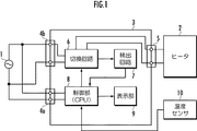
本実施形態の誤配線検知装置は、図1に示す電気床暖房システムにおいて、電源(例えば、商用交流電源)1とこの電源1からの電力供給によって動作する制御対象機器(この場合、床暖房パネルのヒータ)2との間に設けられる制御装置(コントローラ)3に対する電源及びヒータとの誤配線を検知するために、当該コントローラ3内に設けられる下記の切換回路と検出回路とからなる。 In the electric floor heating system shown in FIG. 1, the erroneous wiring detection device according to the present embodiment includes a power source (for example, commercial AC power source) 1 and a control target device that operates by supplying power from the power source 1 (in this case, a floor heating panel). In order to detect an incorrect wiring between the power supply and the heater for the control device (controller) 3 provided between the heater 2 and the heater 2, the following switching circuit and detection circuit provided in the controller 3 are included.
コントローラ3は、図示しないケーブルを介して電源1に接続される2つの電源接続端子部4a,4bと、同様にケーブルを介してヒータ2に接続される機器接続端子部5とを備え、これらの端子部の間に接続された切換回路6、検出回路7、制御部8及び表示部9で構成されている。なお、一の電源接続端子部4aは、電源1から制御部8その他の回路部に給電するための端子、もう一つの電源接続端子部4bは、コントローラ3からヒータ線を介してヒータ2に給電するための端子として設けられている。
The controller 3 includes two power
制御部8は、後述のように構成された切換回路6及び表示部9の動作を制御するCPUと、各回路との接続インタフェースとを含んでいる。また、制御部8には、ヒータ2で加熱される床暖房パネル表面の温度を検出する温度センサ10が接続されている。
The control unit 8 includes a CPU that controls the operation of the switching circuit 6 and the
表示部9は、制御部8からの表示信号に応じて、床暖房の温度制御などに必要な設定データ等の表示を行う表示素子(例えば、液晶画面)と、これを駆動するための表示駆動回路とを含んでいる。
The
切換回路6及び検出回路7は、次のように構成されている。 The switching circuit 6 and the detection circuit 7 are configured as follows.
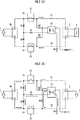
図2(A)に示すように、ヒータ2への通電のための電源接続端子部4bと機器接続端子部5とを結ぶ2本の接続線11,12の途中に、上記コントローラ3からの制御信号CSによって駆動される2つのリレーの接点部13,14が設けられ、これらの接点部が開閉されることで、電源接続端子部4bから機器接続端子部5への通電、従ってヒータへの給電が制御される。このように両端子部の間を結ぶ2本の接続線11,12に設けられた2つの接点部13,14により、切換回路6が構成されている。
As shown in FIG. 2A, control from the controller 3 is provided in the middle of two
また、2つの接点部13,14より電源接続端子部4b側で、2本の接続線11,12の間には、2つのダイオードD1,D2が互いに逆向きに直列接続される一方、2つの接点部13,14より機器接続端子部5側で、2本の接続線11,12の間には、2つの抵抗R2,R3が直列接続されている。そして、ダイオードD1,D2の接続点と抵抗R2,R3の接続点との間に、抵抗R1と、通電検出手段としてのフォトカプラ15の発光部(ダイオード)とが直列接続され、フォトカプラ15の受光部(トランジスタ)は、その一端(この場合、エミッタ側)が抵抗R4を介してアースに接続され、他端(この場合、コレクタ側)は制御部8に接続されている。
In addition, two diodes D1 and D2 are connected in series in opposite directions between the two
ここで、コントローラ3に対する電源1とヒータ2の結線が正しい場合、すなわち、電源接続端子部4bに電源1が接続され且つ機器接続端子部5にヒータ2が接続された場合には、2つのリレーの接点部13,14が閉じると、電源接続端子部4bと機器接続端子部5とを結ぶ2本の接続線11,12のみを経由して電源1からヒータ2へ給電される。従って、2つのリレーの接点部13,14が開閉されることでヒータ2への給電が制御される。
Here, when the connection between the
しかしながら、結線が正しくない誤配線として、図2(B)に示すように、電源1が、電源接続端子部4bに接続されるだけでなく、本来ヒータを接続すべき機器接続端子部5にも接続されることが生じ得る。
However, as shown in FIG. 2 (B), the
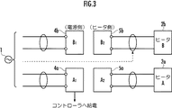
特に、このような接続ミス(誤配線)は、図3に示すように、コントローラ3が2枚の床暖房パネルのヒータ2a,2bに電力を供給する2系統に給電可能な端子部5a,5bを有する場合に起こりやすい。すなわち、1台のコントローラで2つの床暖房パネルの温度(ヒータ)を制御する構成の床暖房装置においては、当該コントローラへの電源線とヒータ線はそれぞれ端子部4aと5aに間違いなく結線されるが、他の床暖房パネル用の電源線とヒータ線については、図3に破線で示すように、電源線をヒータ側の端子5bに接続してしまうことがあり得る。
In particular, such a connection error (miswiring) is caused by
上記のような誤配線の場合、図2(B)の回路では、2つのリレーの接点部13,14が開いていても、電源接続端子部4bと、電源1が誤って接続された機器接続端子部5との間で、機器接続端子部5側の電源1から接続線11及び抵抗R2を通って、或いは接続線12及び抵抗R3を通って、フォトカプラ15の発光部→抵抗R1→ダイオードD1及びD2を経由して電源接続端子部4bに至る経路に電流が流れるので、フォトカプラ15の受光部に所定の電圧が発生して検出信号が制御部8に送られる。これにより、誤配線を検知することができる。このフォトカプラ15と、上記2本の接続線11,12の間に接続されたダイオードD1,D2、抵抗R1,R2,R3とにより、検出回路7が構成されている。
In the case of incorrect wiring as described above, in the circuit of FIG. 2 (B), even if the
また、図2(B)の回路において、第1の接点13と第2の接点14のいずれか一方又は両方が閉じると、両側の電源1が短絡された状態になるので、これを防止するために、上記のように電源1が誤って機器接続端子部5に接続されたときに誤配線を検知することが重要である。
Further, in the circuit of FIG. 2B, when one or both of the
本実施形態では、通電検出手段としてフォトカプラ15を用いることで、ヒータへの給電回路から電気的に絶縁した状態で、誤配線を検出するようにしている。
In the present embodiment, the
なお、図3に示すようなコントローラの端子部においては、本来ヒータを接続する側に電源を、本来電源を接続する側にヒータを夫々接続する誤配線(逆差し)も想定される。この誤配線の場合、図において上側の端子4b,5b(コントローラへの給電を行わない側の端子)に電源とヒータを逆に接続しても、電源からヒータに正常に通電するので、誤配線の検出を行う必要は乏しい。しかしながら、下側の端子4a,5a(コントローラへの給電を行う側の端子)に電源とヒータを逆に接続したときには、コントローラへの給電が行われず、コントローラが動作しないので、誤配線に気づいて修正作業を行うことが可能である。
In addition, in the terminal portion of the controller as shown in FIG. 3, erroneous wiring (reverse insertion) in which the power source is originally connected to the heater and the heater is originally connected to the power source is assumed. In the case of this incorrect wiring, even if the power supply and the heater are connected reversely to the
図1の床暖房システムは、以上のように構成されているので、コントローラ3の制御下で、次のように動作する。 The floor heating system of FIG. 1 is configured as described above, and thus operates as follows under the control of the controller 3.
まず、コントローラ3の端子部に電源1及びヒータ2が正しく接続された状態では、床暖房運転時に、温度センサ10による検出温度が設定温度より低いとコントローラ3が判断したときには、2つのリレーのコイル部を駆動して、対応する接点部13,14を閉じてヒータ2へ通電する。このヒータ2への通電により温度が上昇し、温度センサ10の検出温度が設定温度より高くなったと判断すると、いずれかのリレーへの通電を停止し、対応する接点部13又は14を開いてヒータ2への通電を停止する。以上のような接点部13,14の開閉の繰り返しにより、コントローラ3は、床暖房パネルが予め設定した温度になるように制御している。
First, in a state where the
これに対し、コントローラ3の端子部に電源1が間違って接続された誤配線の状態では、上記のようにフォトカプラ15からの検出信号により制御部8が誤配線を検知し、それに応じた表示信号を表示部9に送って誤配線を知らせる表示をすることができる。
On the other hand, when the
以上のように、本実施形態の誤配線検出回路によれば、床暖房システムの工事段階或いはメンテナンス時に上記のような誤配線が生じた場合には、通電検出手段としてのフォトカプラ15からの出力信号により誤配線を簡単且つ迅速に検知することができるので、従来のように誤配線が床暖房運転まで気づかれないまま放置されて、短絡などによる事故が発生し得るという問題がなくなる。また、検出回路はダイオードや抵抗など簡易な回路素子だけで構成されるので、コントローラ3に加えられる構成も簡単で安価なものである。
As described above, according to the erroneous wiring detection circuit of the present embodiment, when the above-described erroneous wiring occurs during the construction stage or maintenance of the floor heating system, the output from the
以上、実施形態について説明したが、本発明はこれに限らない。例えば、上記のように誤配線を検出するための回路は、フォトカプラに限らず、任意の通電検出手段を備えていればよい。 As mentioned above, although embodiment was described, this invention is not restricted to this. For example, the circuit for detecting miswiring as described above is not limited to a photocoupler, and may include any energization detection means.
1・・・電源、2・・・ヒータ、3・・・コントローラ、4・・・電源接続端子部、5・・・機器接続端子部、6・・・切換回路、7・・・検出回路、8・・・制御部、9・・・表示部、10・・・温度センサ、11,12・・・接続線、13,14・・・接点部、15・・・フォトカプラ。
DESCRIPTION OF
Claims (3)
前記制御装置の電源接続端子部と前記制御対象機器に接続される機器接続端子部との間にそれぞれ接続され、前記制御装置からの制御信号によって開閉される2つの接点部と、
前記2つの接点部と並列に接続され、前記機器接続端子部に前記電源が電気的に接続されたときに誤配線状態を検知する検出信号を出力する検出回路とを備え、
前記2つの接点部が共に開状態にあるときに、前記検出回路が前記機器接続端子部から前記電源接続端子部に至る経路に流れる電流を検出して前記検出信号を出力することにより、前記機器接続端子部に対する電源の誤結線を検知することを特徴とする誤配線検出装置。 A miswiring detection device that detects miswiring for a control device provided between a power source and a control target device that operates by power supply from the power source,
Two contact portions connected between a power connection terminal portion of the control device and a device connection terminal portion connected to the control target device, and opened and closed by a control signal from the control device;
A detection circuit that is connected in parallel with the two contact portions and outputs a detection signal that detects a miswiring state when the power source is electrically connected to the device connection terminal portion;
When the two contact portions are both in an open state, the detection circuit detects a current flowing in a path from the device connection terminal portion to the power connection terminal portion, and outputs the detection signal , whereby the device An erroneous wiring detection device for detecting an erroneous connection of a power source to a connection terminal portion .
Priority Applications (1)
| Application Number | Priority Date | Filing Date | Title |
|---|---|---|---|
| JP2008177807A JP5225770B2 (en) | 2008-07-08 | 2008-07-08 | Incorrect wiring detection device |
Applications Claiming Priority (1)
| Application Number | Priority Date | Filing Date | Title |
|---|---|---|---|
| JP2008177807A JP5225770B2 (en) | 2008-07-08 | 2008-07-08 | Incorrect wiring detection device |
Publications (2)
| Publication Number | Publication Date |
|---|---|
| JP2010019576A JP2010019576A (en) | 2010-01-28 |
| JP5225770B2 true JP5225770B2 (en) | 2013-07-03 |
Family
ID=41704654
Family Applications (1)
| Application Number | Title | Priority Date | Filing Date |
|---|---|---|---|
| JP2008177807A Active JP5225770B2 (en) | 2008-07-08 | 2008-07-08 | Incorrect wiring detection device |
Country Status (1)
| Country | Link |
|---|---|
| JP (1) | JP5225770B2 (en) |
Families Citing this family (2)
| Publication number | Priority date | Publication date | Assignee | Title |
|---|---|---|---|---|
| JP7723384B2 (en) * | 2021-09-24 | 2025-08-14 | Necプラットフォームズ株式会社 | Misconnection prevention device and misconnection prevention method |
| CN115047372A (en) * | 2022-03-03 | 2022-09-13 | 南京华易泰电子科技有限公司 | Short circuit monitoring system based on short circuit monitoring controller |
Family Cites Families (4)
| Publication number | Priority date | Publication date | Assignee | Title |
|---|---|---|---|---|
| JPH0769072B2 (en) * | 1984-10-11 | 1995-07-26 | 株式会社日立製作所 | Wrong connection protection circuit for air conditioner |
| JPH0323807Y2 (en) * | 1985-04-30 | 1991-05-23 | ||
| JPH0236770A (en) * | 1988-07-27 | 1990-02-06 | Mitsubishi Electric Corp | inverter device |
| JP3565054B2 (en) * | 1998-11-02 | 2004-09-15 | 松下電器産業株式会社 | Inverter device protection method |
-
2008
- 2008-07-08 JP JP2008177807A patent/JP5225770B2/en active Active
Also Published As
| Publication number | Publication date |
|---|---|
| JP2010019576A (en) | 2010-01-28 |
Similar Documents
| Publication | Publication Date | Title |
|---|---|---|
| JP5233018B2 (en) | Control device for floor heating | |
| US7755311B2 (en) | Fan abnormality detection device | |
| JP5099039B2 (en) | Robot controller | |
| JP5134145B2 (en) | Distributed power generation system | |
| US8483987B2 (en) | Circuit with control function and test method thereof | |
| EP1744339B1 (en) | Contact welding detecting device for relay | |
| JP6580249B2 (en) | Relay board and sensor device | |
| JP5225770B2 (en) | Incorrect wiring detection device | |
| EP0235393A1 (en) | Method for detection component connection errors in a multicoponent hot melt heating system | |
| JP2015230784A (en) | Contactor failure judgment device | |
| JP5436881B2 (en) | Air conditioner | |
| JP3922461B2 (en) | Terminal control system | |
| US7814869B2 (en) | Hot water supply system | |
| JP6831052B2 (en) | Leakage current detector and heating device | |
| CN104237724B (en) | Detection card and detection system for fan card | |
| JPH07133950A (en) | Air conditioner signal transmission circuit | |
| KR101228546B1 (en) | Three-Phase Input Switching Contol Apparatus Inaccordance With Input Power | |
| KR101046204B1 (en) | Drive control circuit of electric mat | |
| JP5184246B2 (en) | Output circuit and detection switch using the same | |
| JP5796445B2 (en) | Vehicle power supply device | |
| JP2003295702A (en) | Image forming device | |
| JP2007316245A (en) | Image forming apparatus | |
| KR20100122591A (en) | Circuit for controlling electric mat | |
| JP4036181B2 (en) | Gas shut-off device | |
| JP6237219B2 (en) | Heater drive circuit with abnormality detection function |
Legal Events
| Date | Code | Title | Description |
|---|---|---|---|
| A621 | Written request for application examination |
Free format text: JAPANESE INTERMEDIATE CODE: A621 Effective date: 20110307 |
|
| A131 | Notification of reasons for refusal |
Free format text: JAPANESE INTERMEDIATE CODE: A131 Effective date: 20121023 |
|
| A977 | Report on retrieval |
Free format text: JAPANESE INTERMEDIATE CODE: A971007 Effective date: 20121024 |
|
| A521 | Request for written amendment filed |
Free format text: JAPANESE INTERMEDIATE CODE: A523 Effective date: 20121218 |
|
| TRDD | Decision of grant or rejection written | ||
| A01 | Written decision to grant a patent or to grant a registration (utility model) |
Free format text: JAPANESE INTERMEDIATE CODE: A01 Effective date: 20130305 |
|
| A61 | First payment of annual fees (during grant procedure) |
Free format text: JAPANESE INTERMEDIATE CODE: A61 Effective date: 20130313 |
|
| R150 | Certificate of patent or registration of utility model |
Ref document number: 5225770 Country of ref document: JP Free format text: JAPANESE INTERMEDIATE CODE: R150 |
|
| FPAY | Renewal fee payment (event date is renewal date of database) |
Free format text: PAYMENT UNTIL: 20160322 Year of fee payment: 3 |
|
| R250 | Receipt of annual fees |
Free format text: JAPANESE INTERMEDIATE CODE: R250 |
|
| R250 | Receipt of annual fees |
Free format text: JAPANESE INTERMEDIATE CODE: R250 |