JP5226251B2 - Communication method in home automation equipment - Google Patents
Communication method in home automation equipment Download PDFInfo
- Publication number
- JP5226251B2 JP5226251B2 JP2007166764A JP2007166764A JP5226251B2 JP 5226251 B2 JP5226251 B2 JP 5226251B2 JP 2007166764 A JP2007166764 A JP 2007166764A JP 2007166764 A JP2007166764 A JP 2007166764A JP 5226251 B2 JP5226251 B2 JP 5226251B2
- Authority
- JP
- Japan
- Prior art keywords
- receiving element
- receiving
- communication method
- elements
- substitute
- Prior art date
- Legal status (The legal status is an assumption and is not a legal conclusion. Google has not performed a legal analysis and makes no representation as to the accuracy of the status listed.)
- Expired - Fee Related
Links
- 238000000034 method Methods 0.000 title claims description 51
- 238000004891 communication Methods 0.000 title claims description 42
- 230000005540 biological transmission Effects 0.000 claims description 17
- 230000009471 action Effects 0.000 claims description 8
- 230000035945 sensitivity Effects 0.000 claims description 2
- 238000006467 substitution reaction Methods 0.000 claims 2
- 102100031102 C-C motif chemokine 4 Human genes 0.000 description 7
- 101000777470 Mus musculus C-C motif chemokine 4 Proteins 0.000 description 6
- 230000004044 response Effects 0.000 description 6
- 101000908384 Bos taurus Dipeptidyl peptidase 4 Proteins 0.000 description 5
- 102100026620 E3 ubiquitin ligase TRAF3IP2 Human genes 0.000 description 5
- 238000012790 confirmation Methods 0.000 description 5
- 230000000694 effects Effects 0.000 description 5
- 238000012360 testing method Methods 0.000 description 5
- 101710140859 E3 ubiquitin ligase TRAF3IP2 Proteins 0.000 description 4
- 230000002457 bidirectional effect Effects 0.000 description 3
- 238000003860 storage Methods 0.000 description 3
- HEFNNWSXXWATRW-UHFFFAOYSA-N Ibuprofen Chemical compound CC(C)CC1=CC=C(C(C)C(O)=O)C=C1 HEFNNWSXXWATRW-UHFFFAOYSA-N 0.000 description 2
- 230000004913 activation Effects 0.000 description 2
- 238000012986 modification Methods 0.000 description 2
- 230000004048 modification Effects 0.000 description 2
- 238000003825 pressing Methods 0.000 description 2
- 238000012549 training Methods 0.000 description 2
- 238000013459 approach Methods 0.000 description 1
- 239000003990 capacitor Substances 0.000 description 1
- 230000001413 cellular effect Effects 0.000 description 1
- 238000006243 chemical reaction Methods 0.000 description 1
- 238000001514 detection method Methods 0.000 description 1
- 230000005611 electricity Effects 0.000 description 1
- 238000005265 energy consumption Methods 0.000 description 1
- 238000004146 energy storage Methods 0.000 description 1
- 239000000446 fuel Substances 0.000 description 1
- 230000006870 function Effects 0.000 description 1
- 238000004519 manufacturing process Methods 0.000 description 1
- 230000002085 persistent effect Effects 0.000 description 1
- 230000008054 signal transmission Effects 0.000 description 1
- 230000037072 sun protection Effects 0.000 description 1
- 238000012546 transfer Methods 0.000 description 1
- 230000007704 transition Effects 0.000 description 1
- 230000001960 triggered effect Effects 0.000 description 1
Images



Classifications
-
- H—ELECTRICITY
- H04—ELECTRIC COMMUNICATION TECHNIQUE
- H04L—TRANSMISSION OF DIGITAL INFORMATION, e.g. TELEGRAPHIC COMMUNICATION
- H04L12/00—Data switching networks
- H04L12/28—Data switching networks characterised by path configuration, e.g. LAN [Local Area Networks] or WAN [Wide Area Networks]
-
- H—ELECTRICITY
- H04—ELECTRIC COMMUNICATION TECHNIQUE
- H04L—TRANSMISSION OF DIGITAL INFORMATION, e.g. TELEGRAPHIC COMMUNICATION
- H04L12/00—Data switching networks
- H04L12/02—Details
- H04L12/12—Arrangements for remote connection or disconnection of substations or of equipment thereof
-
- H—ELECTRICITY
- H04—ELECTRIC COMMUNICATION TECHNIQUE
- H04L—TRANSMISSION OF DIGITAL INFORMATION, e.g. TELEGRAPHIC COMMUNICATION
- H04L12/00—Data switching networks
- H04L12/02—Details
- H04L12/16—Arrangements for providing special services to substations
-
- H—ELECTRICITY
- H04—ELECTRIC COMMUNICATION TECHNIQUE
- H04L—TRANSMISSION OF DIGITAL INFORMATION, e.g. TELEGRAPHIC COMMUNICATION
- H04L12/00—Data switching networks
- H04L12/28—Data switching networks characterised by path configuration, e.g. LAN [Local Area Networks] or WAN [Wide Area Networks]
- H04L12/2803—Home automation networks
- H04L12/283—Processing of data at an internetworking point of a home automation network
- H04L12/2832—Interconnection of the control functionalities between home networks
-
- H—ELECTRICITY
- H04—ELECTRIC COMMUNICATION TECHNIQUE
- H04L—TRANSMISSION OF DIGITAL INFORMATION, e.g. TELEGRAPHIC COMMUNICATION
- H04L12/00—Data switching networks
- H04L12/28—Data switching networks characterised by path configuration, e.g. LAN [Local Area Networks] or WAN [Wide Area Networks]
- H04L12/2803—Home automation networks
- H04L2012/284—Home automation networks characterised by the type of medium used
- H04L2012/2841—Wireless
-
- H—ELECTRICITY
- H04—ELECTRIC COMMUNICATION TECHNIQUE
- H04L—TRANSMISSION OF DIGITAL INFORMATION, e.g. TELEGRAPHIC COMMUNICATION
- H04L12/00—Data switching networks
- H04L12/28—Data switching networks characterised by path configuration, e.g. LAN [Local Area Networks] or WAN [Wide Area Networks]
- H04L12/2803—Home automation networks
- H04L2012/2847—Home automation networks characterised by the type of home appliance used
- H04L2012/285—Generic home appliances, e.g. refrigerators
-
- Y—GENERAL TAGGING OF NEW TECHNOLOGICAL DEVELOPMENTS; GENERAL TAGGING OF CROSS-SECTIONAL TECHNOLOGIES SPANNING OVER SEVERAL SECTIONS OF THE IPC; TECHNICAL SUBJECTS COVERED BY FORMER USPC CROSS-REFERENCE ART COLLECTIONS [XRACs] AND DIGESTS
- Y02—TECHNOLOGIES OR APPLICATIONS FOR MITIGATION OR ADAPTATION AGAINST CLIMATE CHANGE
- Y02D—CLIMATE CHANGE MITIGATION TECHNOLOGIES IN INFORMATION AND COMMUNICATION TECHNOLOGIES [ICT], I.E. INFORMATION AND COMMUNICATION TECHNOLOGIES AIMING AT THE REDUCTION OF THEIR OWN ENERGY USE
- Y02D30/00—Reducing energy consumption in communication networks
- Y02D30/50—Reducing energy consumption in communication networks in wire-line communication networks, e.g. low power modes or reduced link rate
Landscapes
- Engineering & Computer Science (AREA)
- Computer Networks & Wireless Communication (AREA)
- Signal Processing (AREA)
- Mobile Radio Communication Systems (AREA)
- Selective Calling Equipment (AREA)
- Small-Scale Networks (AREA)
Description
本発明は、電源内蔵型エレメントにあてたホーム・オートメーション装置のエレメント間のコマンド又はデータの転送に関する。そのエレメントは、例えば、無線周波数で互いに通信する。それらは、特に、アクチュエータ、センサ、及びコントロールポイントを有する。 The present invention relates to the transfer of commands or data between elements of a home automation device addressed to a power supply built-in element. The elements communicate with each other on a radio frequency, for example. They have in particular actuators, sensors and control points.
アクチュエータは、一般に、商用電力供給網により給電され、しかし一方、センサ及びコントロールパネルは、一般に、例えば、乾電池又は充電池により給電される。 Actuators are typically powered by a commercial power supply network, while sensors and control panels are typically powered by, for example, dry batteries or rechargeable batteries.
そのような装置において、電源内蔵型エレメントが双方向性タイプになるとすぐに、無線周波数受信器により永続的なリスニングをいかに回避するかという1つの問題が生じる。その永続的なリスニングは、消費を増加させる結果となり、それゆえ自律性を失うことになる。
この問題は、多数の発明を生じさせる。
In such a device, as soon as the self-powered element becomes a bidirectional type, one problem arises as to how to avoid permanent listening by the radio frequency receiver. That persistent listening results in increased consumption and therefore loses autonomy.
This problem gives rise to a number of inventions.
第1の発明グループにおいて、国際出願WO00/28776は、固定時間で起動する受信器を開示する。それゆえ、それらは永続的に給電される少なくとも1つのクロックデバイスを含む必要がある。類似のやり方は、特許出願EP1404043に記載される。 In the first invention group, the international application WO 00/28776 discloses a receiver which starts at a fixed time. Therefore, they need to include at least one clock device that is permanently powered. A similar approach is described in patent application EP1404043.
第2の発明グループは、ルータを使うために、例えば、それらは商用電源網で給電され、又は、大きなエネルギー蓄積により給電しなくてはならないので、電源供給という問題が生じる。特許出願EP1545076は、セルラーネットワークにおける携帯機器の中継としての自動車の使用を記述する。類似の使用が、特許出願JP59092133及びJP11276343に見られる。ホーム・オートメーションに関連する分野では、米国特許6,525,645が、自動車の中に配置され且つその蓄電池によって給電される。識別コードが有効であり、運転手によって携帯される携帯機器により送られる信号は、完全に同じように繰り返されるが、その繰り返しによってさらに電力を有する信号となる。 In order for the second invention group to use routers, for example, they must be powered by a commercial power network, or they must be powered by a large energy storage, resulting in a problem of power supply. Patent application EP 1545076 describes the use of a motor vehicle as a relay for portable devices in a cellular network. Similar uses are found in patent applications JP59092133 and JP11276343. In the field related to home automation, US Pat. No. 6,525,645 is placed in a car and powered by its storage battery. The signal sent by the portable device with valid identification code and carried by the driver is repeated in exactly the same way, but the repetition results in a signal with more power.
米国特許7,027,416もまた、ホーム・オートメーションタイプの装置を記述し、それは、電源内蔵型デバイスの各々が、低電力手段によって、範囲及び消費の両方を減らすことを可能にするように通信する。そのルータは、高電力で、互いに通信し、及び異なる周波数帯にしたがって、低レベル通信に使用される異なるプロトコルで互いに通信する。2つのエレメント間の通信は、少なくとも1つ、一般には、幾つかの使用を要求する。電源内蔵型エレメントは、周期的に、又は、ランダムに予め決められた負荷比率にしたがって動作停止する。そのようなエレメントと通信しなければならないルータは、この操作様式を通知され、通信時を規定することに注意する。エレメントは直接的に互いに通信することは提供されない。このことは、階層化されたノットワークの性質によって説明され、且つ、ローカル及び/又は例えば電話網を介したリモートコントローラによって判断がとられるという事実によって説明される。コントローラは、ローカルルーティングテーブルの知識に基づいて、メインルーティングテーブルも管理する。 US Pat. No. 7,027,416 also describes a home automation type device, which communicates to allow each of the self-powered devices to reduce both range and consumption by low power means. To do. The routers communicate with each other at high power and with different protocols used for low level communication according to different frequency bands. Communication between two elements requires at least one, generally several uses. The built-in power supply type element stops operation according to a predetermined load ratio periodically or randomly. Note that routers that must communicate with such elements are informed of this mode of operation and specify when to communicate. Elements are not provided to communicate directly with each other. This is explained by the nature of the layered network and by the fact that decisions are taken locally and / or by a remote controller, for example via a telephone network. The controller also manages the main routing table based on knowledge of the local routing table.
発明の第3のグループは、「メールボックス」タイプのリピータの使用を記述する。
米国特許4,803,487は、リモートディスプレイ手段と共にポケベルのケースを取り扱っている。例えば、主受信機又は第1の受信機が、メッセージを受信しそれをメモリに記憶する。高容量のバッテリーで給電されるにもかかわらず、エコノマイザーデバイスがそのポケベルがメッセージの宛先で無い場合、所与の時間間隔でスリープ状態になることを試みる。この主受信機は、リモートディスプレイを有する恐らくは双方向手段により通信する。ディスプレイと第1の受信機との間のリンクは、各ポケベルへメッセージを送信するために使用される通信プロトコルから、異なるプロトコルと共に実行される。ユーザ制御の起動と共に、リモートディスプレイの送信機は、第1の受信機に問合せ、そして第1の受信機は、メモリに格納された情報を、リモートディスプレイの受信機に送信する。
A third group of inventions describes the use of "mailbox" type repeaters.
U.S. Pat. No. 4,803,487 deals with a pager case with remote display means. For example, the main receiver or the first receiver receives the message and stores it in memory. Despite being powered by a high-capacity battery, the economizer device attempts to sleep at a given time interval if the pager is not the message destination. This main receiver communicates with a remote display, possibly by bidirectional means. The link between the display and the first receiver is performed with a different protocol from the communication protocol used to send the message to each pager. Upon activation of user control, the remote display transmitter queries the first receiver, and the first receiver transmits the information stored in the memory to the remote display receiver.
それゆえ、従来技術は、幾つかの通信手段又はプロトコルを支持する複雑な構造を求め、又は、携帯リモート制御用の制限された性能でも単一の通信手段を提供し、そのとき、受信ではなく送信において消費を削減するという観点から問題を処理する。特に、問題は、携帯リモート制御を容易にアクセスできない(および、そのためにセルを取り替えるのが困難な)センサに置き替える場合に生じ、インテリジェントリレーが、それ自身電源内蔵型であり又は形態可能であるときなおいっそう生じる。 Therefore, the prior art seeks a complex structure that supports several communication means or protocols, or provides a single communication means with limited performance for portable remote control, when not receiving Address the problem in terms of reducing consumption in transmission. In particular, the problem arises when the portable remote control is replaced with a sensor that is not easily accessible (and thus it is difficult to replace the cell), and the intelligent relay is itself self-powered or configurable Sometimes even more.
さらに、公開番号US2006/0025181は、ネットワーク上を通信するエレメントセットを有する装置を開示する。エレメントの1つは、ネットワークの部分を形成しない電源内蔵型の端末とさらに通信する。この電源内蔵型の端末は、その自律性を最適化するために、起動状態及びスリープ状態を交代するサイクルにしたがって動作する。したがって、ネットワークのエレメントが端末にデータの送信を望む一方で端末がスリープ状態のケースでは、このネットワークエレメントは、メモリにデータを格納し、それが実際にデータを送信する前に、電源内蔵型端末の起動情報を待つ。この装置では、送信及び受信の両方において、単一のエレメントと通信することができるだけであり、ネットワークのエレメントと端末の通信の可能性は、非常に制限されている。 Further, publication number US 2006/0025181 discloses a device having an element set communicating over a network. One of the elements further communicates with a self-powered terminal that does not form part of the network. This power supply built-in terminal operates according to a cycle that switches between a start state and a sleep state in order to optimize its autonomy. Thus, in the case where the network element wants to transmit data to the terminal while the terminal is in the sleep state, this network element stores the data in memory and before it actually transmits the data, the self-powered terminal Wait for startup information. This device can only communicate with a single element in both transmission and reception, and the possibility of communication between the elements of the network and the terminal is very limited.
本発明の目的は、前述の欠点を未然に防ぎ、且つ、従来技術で知られた通信方法を改良することを可能にする通信方法を提供することである。特に、本発明に係る通信方法は、ホームオートメーション・エレメントのネットワークとして組織化されるホームオートメーション装置の電源内蔵型のエレメントの通信のためのエネルギー消費を最小化し、特に、信号送信フェーズの他に消費されるエネルギーを最小化する可能にする。 The object of the present invention is to provide a communication method which obviates the above-mentioned drawbacks and makes it possible to improve the communication method known in the prior art. In particular, the communication method according to the present invention minimizes energy consumption for communication of power-integrated elements of a home automation device organized as a network of home automation elements, in particular in addition to the signal transmission phase. Allows to minimize the energy being played.
上記通信方法は、少なくとも1つの送信エレメント、電源内蔵型の受信エレメント、及び、受信エレメントを代替するための代替エレメントを有するホームオートメーション装置に適用される。送信エレメント、受信エレメント、置換用エレメントは同一のネットワーク(RFN)に属する。受信エレメントがスリープモードにある場合、代替エレメントは、送信エレメントにより送信される受信エレメント宛の情報を受信及び記憶し、受信エレメントが、もはやスリープモードでない場合、代替エレメントは、受信エレメント宛の情報を送信する。 The above communication method is applied to a home automation apparatus having at least one transmission element, a power receiving type reception element, and an alternative element for replacing the reception element. The transmission element, the reception element, and the replacement element belong to the same network (RFN). If the receiving element is in sleep mode, the alternate element receives and stores information destined for the receiving element transmitted by the transmitting element, and if the receiving element is no longer in sleep mode, the alternate element stores information destined for the receiving element. Send.
受信エレメントがスリープモードでない場合、情報は、送信エレメント及び受信エレメント間で直接送信される。 If the receiving element is not in sleep mode, information is transmitted directly between the transmitting element and the receiving element.
受信エレメントがスリープモードであり且つ情報の受信が生じる場合、代替エレメントは、代替エレメントの識別子を受信エレメントの識別子に置換することによって情報が適切に受信されたことを送信エレメントに対して確認することができる。 If the receiving element is in sleep mode and reception of information occurs, the replacement element confirms to the transmitting element that the information has been properly received by replacing the identifier of the replacement element with the identifier of the receiving element Can do.
代替エレメントは受信エレメントがスリープモードに入ることに関するメッセージを受信エレメントから受信した後でのみ、代替エレメントは送信エレメントにより送信された受信エレメント宛の情報を受信及び記録することができる。 Only after the substitute element receives a message from the receiving element about the receiving element entering sleep mode, the substitute element can receive and record the information destined for the receiving element sent by the sending element.
代替エレメントは代替エレメントにより受信され且つ受信エレメントにより送信された最後のメッセージの受信の後の所定の時間を計測した後でのみ、代替エレメントは送信エレメントにより送信された受信エレメント宛の情報を受信及び記録することができる。 Only after a predetermined time has elapsed since the reception of the last message received by the replacement element and transmitted by the reception element, the replacement element receives and sends information destined for the reception element transmitted by the transmission element. Can be recorded.
代替エレメントは幾つかの受信エレメントのために代替エレメント自身を代替可能である。 An alternative element can replace the alternative element itself for some receiving elements.
代替エレメントは、事前の指定手続の過程で装置のエレメントの中から指定されることができる。 Alternative elements can be specified from among the elements of the device during the pre-specified procedure.
代替エレメントは、受信エレメントにより送信される信号の受信レベルが、代替エレメントになる能力がある様々なエレメントにおいて測定される事前の習得手続の過程で決定されることができる。 The replacement element can be determined in the course of a prior learning procedure in which the reception level of the signal transmitted by the receiving element is measured at various elements capable of becoming the replacement element.
信号は、受信エレメントにより減少された電力において送信されることができる。 The signal can be transmitted at reduced power by the receiving element.
信号受信感度は、代替エレメントになる能力を有する装置の各エレメントにおいて減少されることができる。 The signal reception sensitivity can be reduced at each element of the device that has the ability to be a substitute element.
本発明に係るホームオートメーション装置は、少なくとも1つの送信エレメント、電源内蔵型受信エレメントを有する。それは、ハードウェア及び上述の通信方法を実行することを特徴とする。 The home automation apparatus according to the present invention includes at least one transmission element and a power supply type reception element. It is characterized by executing the hardware and the communication method described above.
添付の図面は、例証として、本発明に係るホームオートメーション装置の実施例、及び、本発明に係る通信方法の実施形態を説明する。 The accompanying drawings illustrate, by way of example, an example of a home automation device according to the present invention and an embodiment of a communication method according to the present invention.
図1に表されるホームオートメーションの装置INSTでは、様々なエレメントSRU、MMI、SBU、ACT1、ACT2、ACT3が、二重線で表される同一の無線周波数ネットワークRFN上を通信する。エレメント間の通信は、各エレメントのアドレス又は識別子によって区別され、双方向の送信機RX/TXによって実行される。その装置は、電気ネットワークEPNによって電力を供給されるエレメントACT1、ACT3を有し、一方、他のエレメントSRU、MMI、ACT2は、電源内蔵型である。ネットワークのエレメント間の通信は、特に赤外線通信手段のような他の手段によって確実にされ得る。様々なエレメントが、同一の通信プロトコルを使用する。 In the home automation device INST represented in FIG. 1, various elements SRU, MMI, SBU, ACT1, ACT2, ACT3 communicate over the same radio frequency network RFN represented by a double line. Communication between elements is distinguished by the address or identifier of each element and is performed by the bidirectional transmitter RX / TX. The device has elements ACT1, ACT3 powered by the electrical network EPN, while the other elements SRU, MMI, ACT2 are of built-in power supply type. Communication between the elements of the network can be ensured by other means, in particular infrared communication means. Various elements use the same communication protocol.
電源内蔵型センサ又はセンサユニットSRUのアドレスは、@SRUで示され、電源内蔵型センサ又はセンサユニットSRUは、気候又は快適さのパラメータ値を、デジタル数量及び/又は比較閾値に基づいて設定された制御コマンドに変換する。 The address of the self-powered sensor or sensor unit SRU is indicated by @SRU, and the self-powered sensor or sensor unit SRU has a climate or comfort parameter value set based on a digital quantity and / or a comparison threshold. Convert to control command.
マンマシンインタフェースMMIハウジングのアドレスは、@MMIで示され、マンマシンインタフェースMMIハウジングは、エレメントにユーザコマンドを送信することを可能にし、又は、状態メッセージを表示することを可能にする。これらの2つのエレメントは、電源内蔵型である。マンマシンインタフェースは、例えば、キーパッド及びスクリーンを有する携帯リモートコントロールである。 The address of the man-machine interface MMI housing is indicated by @MMI, which allows a user command to be sent to the element or to display a status message. These two elements are of a built-in power source type. The man machine interface is, for example, a portable remote control having a keypad and a screen.
第1のアクチュエータACT1のアドレスは、@ACT1で示され、第1のアクチュエータACT1は、巻き上げ式ブラインド、ドア、又は門の操縦を動作させる。この第1のアクチュエータは、電気ネットワークEPN上で給電される。 The address of the first actuator ACT1 is indicated by @ ACT1, and the first actuator ACT1 operates a roll-up blind, a door, or a gate maneuver. This first actuator is powered on the electrical network EPN.
第2のアクチュエータACT2のアドレスは、@ACT2で示され、第2のアクチュエータACT2は、内部太陽光保護の操縦を作動させる。この第2のアクチュエータは、電源内蔵型である。 The address of the second actuator ACT2 is indicated by @ ACT2, and the second actuator ACT2 activates the internal sun protection maneuver. The second actuator is a built-in power source type.
第3のアクチュエータACT3のアドレスは、@ACT3で示され、第3のアクチュエータACT3は、発光手段を動作させる。例えば、それは、調光器、及び、蛍光灯ランプである。それは、電気ネットワークEPNから給電される。 The address of the third actuator ACT3 is indicated by @ ACT3, and the third actuator ACT3 operates the light emitting means. For example, it is a dimmer and a fluorescent lamp. It is powered from the electrical network EPN.
ネットワークのエレメントの各々のアドレス又は識別子は、それらが通信しそうなネットワークの他のエレメントの全てに知られている。そのアドレス又は識別子の記録は、当業者のよく知る構成又はペアリング手順のステップ間に生じる。このようにして、アクチュエータは、それらが制御コマンドをどっちのコントロールユニットから受信したかを知る。 The address or identifier of each element of the network is known to all other elements of the network with which they are likely to communicate. The recording of that address or identifier occurs during the steps of the configuration or pairing procedure familiar to those skilled in the art. In this way, the actuators know which control unit they received the control command from.
ホームオートメーションネットワークRFNの全てのエレメントは、特に、エネルギー電源内蔵型エレメントは、ハウス・キーと呼ばれる同じ認証鍵を使用して、ホームオートメーションネットワークのメンバーシップを認識することを可能にする。 All elements of the home automation network RFN, in particular, the self-powered element, make it possible to recognize the membership of the home automation network using the same authentication key called the house key.
エネルギー電源内蔵型エレメントは、例えば太陽電池センサのような非電気エネルギーを電気エネルギーに変換可能な手段と共に、乾電池、あるいは、蓄電池、スーパーコンデンサ、燃料電池によって給電される。 The element with built-in energy power supply is powered by a dry battery, a storage battery, a super capacitor, or a fuel cell together with a means capable of converting non-electric energy into electric energy such as a solar cell sensor.
その装置の特定のエレメントSBUは、「代替エレメント」と称される。このエレメントは、好ましくは、破線で表されるような電気ネットワークEPN上で給電される。変形例として、その代替エレメントは、エネルギー電源内蔵型であるが、本発明にかかる通信方法を実行する他の電源内蔵型エレメントよりずっと大きな自律性を有する。代替エレメントのアドレスは、@SBUで示される。代替エレメントは、情報を記憶することができるメモリMEMを含む。代替エレメントは、それ自身、電気ネットワークで給電されるアクチュエータの中に含まれるのが好ましいが、本発明に係る通信方法の実行を可能にするただ1つの機能を有する分割したエレメントであっても良い。 The particular element SBU of the device is referred to as an “alternative element”. This element is preferably powered on the electrical network EPN as represented by the dashed line. As a variant, the alternative element is self-powered, but has a much greater autonomy than other power-powered elements that implement the communication method according to the invention. The address of the alternative element is indicated by @SBU. The alternative element includes a memory MEM that can store information. The alternative element is itself preferably included in the actuator fed by the electrical network, but it may also be a separate element having only one function that enables the communication method according to the invention to be carried out. .
上記方法の利点は、とても小さな値の負荷比率(動作状態期間及びスリープ状態期間の間の比率)であると共に、電源内蔵型のエレメントが、スリープ状態に入るための情報の宛先であることを許可することである。反対に、代替エレメントは、永久的にリッスンし、又は、いかなる無線メッセージの受領も保障するために十分な負荷比率で動作する。 The advantages of the above method are a very small value of the load ratio (ratio between the active state period and the sleep state period) and allow the self-powered element to be the destination of information for entering the sleep state It is to be. Conversely, the alternate element listens permanently or operates at a load ratio sufficient to ensure receipt of any wireless message.
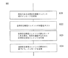
上記方法の動作のモードは、図2に概略的に表され、そこでは、そのモードは、代替エレメントSBUによって実行される。 The mode of operation of the method is schematically represented in FIG. 2, where the mode is executed by the alternative element SBU.
第1のステップE21では、代替エレメントは、代替エレメントが宛先となっていないが、代替エレメントに知られている電源内蔵型の受信エレメントに向けられている情報を送信エレメントから受信する。代替エレメントが電源内蔵型の受信エレメントを突き止めることを可能にする指定又は習得方法は、後述される。 In the first step E21, the substitute element receives information from the transmitting element that is not destined for the substitute element, but that is directed to the self-powered receiving element known to the substitute element. A specification or learning method that allows an alternative element to locate a self-powered receiving element is described below.
第2のステップE22では、代替エレメントが、電源内蔵型受信エレメントがスリープモードにあることを確認する。電源内蔵型受信エレメントが、スリープモードで無い場合、上記方法は、最初の無線リスニングフェーズに戻る。他方、代替エレメントは、電源内蔵型受信エレメントがスリープモードであると判断すると、次に、第3のステップE23に入り、そのステップで、代替エレメントが、そのメモリMEMに情報を記憶し、そして、送信エレメント宛の受信確認メッセージを送信することで、情報の適切な受信を知らせる。代替エレメントは、この受信確認メッセージの中で、代替エレメント自身のアドレスを受信する電源内蔵型エレメントのアドレスに置き換える。したがって、この瞬間に、送信エレメントのために、その情報は効果的に受信エレメントに送信される。 In the second step E22, the alternative element confirms that the power receiving type receiving element is in the sleep mode. If the self-powered receiving element is not in sleep mode, the method returns to the initial wireless listening phase. On the other hand, if the alternative element determines that the self-powered receiving element is in sleep mode, it then enters a third step E23, where the alternative element stores information in its memory MEM, and Sending a receipt confirmation message addressed to the sending element informs the proper reception of information. In this reception confirmation message, the substitute element replaces the address of the substitute element itself with the address of the power built-in element that receives the substitute element. Therefore, at this moment, for the transmitting element, the information is effectively transmitted to the receiving element.
第4のステップE24では、電源内蔵型受信エレメントによる問合せで、代替エレメントは、メモリに記憶した情報を電源内蔵型受信エレメントに送信する。その問合せは、電源内蔵型受信エレメントによって特に指定されるメッセージを有し、あるいは、その問合せは、電源内蔵型受信エレメント起動時はどんなときでも電源内蔵型受信エレメントによる特に指定を有さないブロードキャストメッセージを有する。 In a fourth step E24, the substitute element transmits the information stored in the memory to the power supply type reception element in response to the inquiry by the power supply type reception element. The query has a message that is specifically designated by the self-powered receiving element, or the query is a broadcast message that has no special designation by the power-powered receiving element at any time when the power-powered receiving element is activated. Have
図3は、タイムチャート形式で上から下への時間推移におけるエレメント間の変換の第1の実施例による方法の適用を表す。 FIG. 3 represents the application of the method according to the first embodiment of the conversion between elements in a time transition from top to bottom in the form of a time chart.
左縦線は、センサSRU、マンマシンインタフェースMMI又は第2のアクチュエータACT2の装置の電源内蔵型エレメントを1例として構成する電源内蔵型受信エレメントSAUを指定する。右縦線は、代替エレメントSBUから構成される。代替エレメントは、既に電源内蔵型受信エレメントを突き止めていること等などを仮定する。 The left vertical line designates a power-supplied receiving element SAU that constitutes an example of the power-supplied element of the device of the sensor SRU, the man-machine interface MMI or the second actuator ACT2. The right vertical line is composed of alternative elements SBU. It is assumed that the alternative element has already found the power receiving type receiving element.
最初の状態では、電源内蔵型受信エレメントSAUは、例えば、その内部クロックより作動し、又は、他の理由のために、その活動を完了する。それから、第1のステップE31に入り、そのステップでは、受信エレメントは、受信エレメントがスリープモードに入ることを通知し、これが、メッセージ「SLP」によって表される。このメッセージを受信すると、代替エレメントは受信を確認し(確認は図示せず)、第2のステップE32では、電源内蔵型受信エレメントのスリープ状態を記録するために、代替エレメントは、内部指示器SLPを高い状態に切り替える。 In the initial state, the self-powered receiving element SAU operates for example from its internal clock or completes its activity for other reasons. Then, a first step E31 is entered, in which the receiving element notifies the receiving element to enter sleep mode, which is represented by the message “SLP”. Upon receipt of this message, the substitute element confirms receipt (confirmation is not shown), and in a second step E32, the substitute element contains an internal indicator SLP to record the sleep state of the self-powered receive element. Switch to a higher state.
その一例として、電源内蔵型受信エレメントは、スリープモードに入り、そしてそのスリープモードは、二重線で示される。 As an example, the self-powered receiving element enters a sleep mode, and the sleep mode is indicated by a double line.
第3のステップE33では、メッセージMSGは、電源内蔵型受信エレメントに宛てられ、送信エレメントと称され且つXXXと表示されるその装置の別のエレメントから発せられる。この送信エレメントは、任意である。例えば、操作コマンドが確かに実行される電源内蔵型受信エレメント(マンマシンインタフェースMMIを有する携帯リモート制御)に信号を出したい第3のアクチュエータACT3である。あるいは、送信エレメントXXXは、その新しい応答閾値の値を、センサSRUに示したい携帯リモート制御である。 In a third step E33, the message MSG is addressed to the self-powered receiving element and originates from another element of the device, referred to as the transmitting element and labeled XXX. This transmission element is optional. For example, the third actuator ACT3 that wants to output a signal to a power supply built-in receiving element (mobile remote control having a man-machine interface MMI) in which an operation command is surely executed. Alternatively, the transmitting element XXX is a portable remote control that wants to indicate its new response threshold value to the sensor SRU.
このメッセージは、スリープモードにある電源内蔵型受信エレメントによって読み取られないが、代替エレメントによって取得される。 This message is not read by the self-powered receiving element in sleep mode, but is acquired by the alternative element.
第4のステップE34では、代替エレメントSBUは、内部指示器SLPの状態をテストする。内部指示器SLPが高い状態であるので、メッセージMSGは、代替エレメントで記録され、受信確認の第5ステップE35がトリガーされる。このステップの過程では、代替エレメントは受信エレメントの識別を取得し、即ち、受信確認メッセージの中で、代替エレメント自身のアドレスの代わりに電源内蔵型受信エレメントの識別子又はアドレスを示す。それから、送信エレメントは、適切な受信があることに気付き、それゆえ、ネットワークを不必要に充填する多数の送信に着手しないように、現状の送信セッションを完了する。 In a fourth step E34, the substitute element SBU tests the state of the internal indicator SLP. Since the internal indicator SLP is in a high state, the message MSG is recorded with the alternative element and the fifth step E35 of reception confirmation is triggered. In the course of this step, the substitute element obtains the identity of the receiving element, i.e. indicates the identifier or address of the self-powered receiving element instead of the address of the substitute element itself in the acknowledgment message. The transmitting element then notices that there is proper reception and therefore completes the current transmission session so as not to undertake multiple transmissions that unnecessarily fill the network.
受信エレメントSAUが起動した(二重縦線の終わりで)後で、第6のステップE36に入り、そこでは、受信エレメントが、代替エレメントに受信エレメントが再びアクティブであることを通知し、これはメッセージ「AWK」によって表される。これは、第7のステップE37で、内部指示器SLPを低い状態に切り替える効果を有し、第8のステップE38に入り、代替エレメントに格納されるメッセージMSGが、受信エレメント宛にして送信されるという効果を有する。このステップE38は、代替エレメントが、それ自身の識別子を送信エレメントの識別子に置換することができる。したがって、通信方法は、受信エレメントに関して透過的である、即ちそれに関する限り、受信エレメントが送信エレメントから直接メッセージMSGを受信したかのように全てが生じる。 After the receiving element SAU has been activated (at the end of the double vertical line), a sixth step E36 is entered, where the receiving element notifies the alternate element that the receiving element is active again, which is It is represented by the message “AWK”. This has the effect of switching the internal indicator SLP to the low state in the seventh step E37, and enters the eighth step E38, where the message MSG stored in the alternative element is transmitted to the receiving element. It has the effect. This step E38 allows the alternative element to replace its own identifier with the identifier of the transmitting element. Thus, the communication method is transparent with respect to the receiving element, ie as far as it is concerned, everything happens as if the receiving element received the message MSG directly from the transmitting element.
この第1の例において、通信方法の第2のステップE22は、それゆえ、受信エレメントそれ自身によって通信されるスリープ状態の性質に関するテストによって実行される。 In this first example, the second step E22 of the communication method is therefore performed by a test on the nature of the sleep state communicated by the receiving element itself.
図4は、第2の例を構成し、そこで通信方法のステップE22が異なって実行される。この第2の実施例は、電源内蔵型受信エレメントに宛てられるメッセージへの応答が無い場合の検出に基づいている。この応答の欠如は、電源内蔵型エレメントのスリープモードに関連することが仮定される。 FIG. 4 constitutes a second example in which step E22 of the communication method is performed differently. This second embodiment is based on detection when there is no response to a message addressed to the power receiving element. This lack of response is assumed to be related to the sleep mode of the self-powered element.
第1のステップE41では、メッセージMSGは、電源内蔵型受信エレメントSAUにその宛先が宛てられ、送信エレメントと呼ばれ且つXXXと称されるその装置の別なエレメントから生じる。この瞬間では、受信エレメントは、スリープモードであり、2重線で表される。このメッセージは、受信エレメントによって理解されないが、代替エレメントによって取得され、それから、代替エレメントは、タイムアウトを開始する第2ステップE42をトリガーする。このタイムアウトの間に、代替エレメントは、例えば受信確認の形式で、電源内蔵型受信エレメントから応答が無いかどうかをテストする。さらに一般的な様式では、代替エレメントは、電源内蔵型受信エレメント側に送信アクティビティがあるかどうかをテストする。このテストは、無線アクティビティがタイムアウト期間中に電源内蔵型受信エレメント側で検出されないならば、代替エレメントによってメッセージMSGの記憶と共に終了するという第3のステップE43の課題を形成し、そして、代替エレメントは受信エレメントがスリープモード状態になっていることを結論付ける。この場合、受信確認第4のステップE44に入る。このステップの過程では、代替エレメントは、受信エレメントの識別を取得し、即ち、代替エレメントは、受信確認内でその代替エレメント自身のアドレスの代わりに電源内蔵型受信エレメントの識別子又はアドレスを示す。 In a first step E41, the message MSG is addressed to the self-powered receiving element SAU and originates from another element of the device called the transmitting element and called XXX. At this moment, the receiving element is in sleep mode and is represented by a double line. This message is not understood by the receiving element, but is obtained by the alternative element, which then triggers a second step E42 that initiates a timeout. During this timeout, the alternative element tests whether there is no response from the self-powered receiving element, for example in the form of an acknowledgment. In a more general manner, the alternative element tests for transmission activity on the self-powered receiving element side. This test forms the challenge of the third step E43 that if the wireless activity is not detected on the side of the self-powered receiving element during the timeout period, it ends with the storage of the message MSG by the replacement element, and the replacement element is Conclude that the receiving element is in sleep mode. In this case, the reception confirmation fourth step E44 is entered. In the course of this step, the substitute element obtains the identity of the receiving element, ie the substitute element indicates the identifier or address of the self-powered receiving element instead of its own address in the acknowledgment.
それから、送信エレメントは、適切な受信があることに気付き、それゆえ、現状の送信セッションを、ネットワークに不必要に充填する多数の送信を生じないように完了する。 The transmitting element then notices that there is proper reception and therefore completes the current transmission session so as not to cause a large number of transmissions that unnecessarily fill the network.
受信エレメントSAUが起動又はもっと一般的には作動モード(二重線の末端)に戻った後で、第5のステップE45に入り、そのステップで、メッセージ「AWK」で示される受信エレメントが再びアクティブであることを通知する。これは、第6のステップE46が入ることをもたらし、そのステップでは、代替エレメントに格納されるメッセージMSGが、受信エレメント宛に送信される。このステップE46では、代替エレメントは、代替エレメント自身の識別子を送信エレメントの識別子に置換する。したがって、通信方法は、受信エレメントに関して透過的である、即ち、それに関する限り、受信エレメントが送信エレメントから直接メッセージMSGを受信したかのように全てが生じる。 After the receiving element SAU is activated or more generally returned to operating mode (end of double line), a fifth step E45 is entered, at which the receiving element indicated by the message “AWK” is active again. Notify that. This results in the entry of a sixth step E46, in which the message MSG stored in the alternative element is sent to the receiving element. In this step E46, the substitute element replaces the identifier of the substitute element itself with the identifier of the transmission element. The communication method is therefore transparent with respect to the receiving element, ie as far as it is concerned everything happens as if the receiving element received the message MSG directly from the transmitting element.
変形例において、受信エレメントのスリープ又は起動状態を含むメッセージは、メッセージの送信者を示すが、宛先を特定しないブロードキャストモードにしたがって送信される。そのとき、関連する代替エレメントのみがそのメッセージを使用する。 In a variant, the message including the sleep or activation state of the receiving element is transmitted according to a broadcast mode that indicates the sender of the message but does not specify a destination. Only the relevant alternative element then uses the message.
同一の代替エレメントは、幾つかの電源内蔵型受信エレメントをそれ自身に置換し、即ち、個々の知識を有するという条件で、幾つかの電源内蔵型エレメントに宛てられたメッセージを記憶する。 The same replacement element replaces several self-powered receiving elements with itself, i.e. stores messages addressed to several self-powered elements, provided that it has individual knowledge.
図5は、代替エレメントを指定する方法を記述する。第1のステップE51では、習得モードに入るためのコマンドが、代替エレメントに関するデバイスのアクションによって、選択された代替エレメントSBUに送信される。例えば、そのアクションは、代替エレメントSBUを電気供給網に繋がる電子ソケットに差し込むという事実であっても良い。代替エレメントが、アクチュエータの1つの中に含まれる場合、そのアクションは、そのアクチュエータと既にペアになるリモートコントロールからの特定のプログラミング信号を送信することであっても良い。 FIG. 5 describes a method for specifying an alternative element. In a first step E51, a command for entering the learning mode is sent to the selected substitute element SBU by the action of the device regarding the substitute element. For example, the action may be the fact that the alternative element SBU is plugged into an electronic socket that connects to the electricity supply network. If an alternative element is included in one of the actuators, the action may be to send a specific programming signal from a remote control that is already paired with the actuator.
第2のステップE52では、受信エレメントのアドレスを含む無線信号を送信するために、電源内蔵型受信エレメントSAU(SRU、MMI、ACT2)上にアクションがある。このアクションは、例えば、電源内蔵型受信エレメントの中に接触を作動させるキーの押下である。 In a second step E52, there is an action on the self-powered receiving element SAU (SRU, MMI, ACT2) to transmit a radio signal containing the address of the receiving element. This action is, for example, the pressing of a key that activates a contact in the power receiving element.
第3のステップE53では、電源内蔵型エレメント@SAUのアドレスは、代替エレメントによって記録され、そして代替エレメントは、その自身のアドレス@SBUを示すメッセージを、電源内蔵型受信エレメントに送信する。この第3のステップの完了で、代替エレメントは、代替エレメントが置換等するための電源内蔵型受信エレメントを突き止める。しかしながら、代替エレメントが電源内蔵型エレメントに知られる必要は無い。 In a third step E53, the address of the self-powered element @SAU is recorded by the replacement element, and the replacement element sends a message indicating its own address @SBU to the power-powered reception element. Upon completion of this third step, the substitute element locates the self-powered receiving element for the substitute element to replace. However, there is no need for the alternative element to be known to the power supply built-in element.
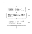
図6は、代替エレメントを構成する方法を記述する。第1のステップE61では、電源内蔵型受信エレメントのアドレスを含む特定の無線信号を送信するために、電源内蔵型受信エレメント上でアクションが生じる。このアクションは、例えば、電源内蔵型受信エレメントにおいて接触を作動させる特定のキーの押下である。 FIG. 6 describes a method for configuring alternative elements. In a first step E61, an action is generated on the power supply receiving element to transmit a specific radio signal including the address of the power supply receiving element. This action is, for example, the pressing of a specific key that activates a contact in the power receiving element.
この特定の無線信号は、例えば、養成モードに入るための特定のコマンドを含む。好ましくは、特定の無線信号が、減少された電力状態で送信される。 This specific radio signal includes, for example, a specific command for entering a training mode. Preferably, certain radio signals are transmitted with a reduced power state.
第2のステップE62では、信号は、リスニングしている装置の全エレメントによって受信され、受信された信号の電力にしたがって、代替エレメントになるための必要な手段も有する非電源内蔵型エレメント又は高容量電力供給を有する非電源内蔵型エレメントは、受信した信号の電力にしたがってランク付けされる。そのランク付けは、次のような様式で実行される。信号の受信後のランダムな期間と共に、エレメントの1つは、その識別子及びその受信したレベル値を含むメッセージを無線ネットワーク上にトークし、又は、ブロードキャストする。この第1のブロードキャストの後に、この値より大きなレベルを受信したエレメントのみが、受信したレベル値の第2のブロードキャスト間にトークすることが承認される。とても素早く、装置の複雑性に依存して、最高の状態下にある信号を受信したエレメントのみが、まだ残る。この方法にしたがって、このエレメントはそれから代替エレメントになる。 In a second step E62, the signal is received by all the elements of the listening device and the non-powered element or high capacity also has the necessary means to become an alternative element according to the power of the received signal Non-powered elements with power supply are ranked according to the power of the received signal. The ranking is performed in the following manner. Along with a random period after receipt of the signal, one of the elements talks or broadcasts a message on the wireless network that includes its identifier and its received level value. Only elements that receive a level greater than this value after this first broadcast are allowed to talk during the second broadcast of the received level value. Only the element that received the signal under the best conditions still remains very quickly, depending on the complexity of the device. According to this method, this element then becomes an alternative element.
第3ステップE63では、代替エレメントのアドレスを含むメッセージは、受信エレメントに送信され、一方では、代替エレメントは、それが置換するための受信エレメントのアドレスを記録する。或いは、第1のステップE61の送信後にスリープモードに入る受信エレメントは、所定のタイムアウト後に起動し、それが起動したことを信号で送るための信号をブロードキャストする。(第2のステップE62間に決定された)最高の状態下の信号を受信したエレメントのみが、そのアドレスと通信することによって応答する。 In a third step E63, a message containing the address of the alternative element is sent to the receiving element, while the alternative element records the address of the receiving element that it replaces. Alternatively, the receiving element that enters the sleep mode after transmission of the first step E61 is activated after a predetermined timeout and broadcasts a signal to signal that it has been activated. Only the element that received the signal under the highest condition (determined during the second step E62) responds by communicating with its address.
記述した実施例から現れることは、代替エレメントが、絶対的に、それが置換する受信エレメントの識別子を突き止めることである。他方では、逆は不要である。特に、受信エレメントによって代替エレメントに信号を送信する図3のステップE36及び図4のステップE45は、この信号が行き先となるエレメントを記述することなく、受信エレメントによってブロードキャストするステップに好適にも置換しても良い。このケースでは、第2のステップE53及びE63の最後のフェーズは、削除される。さらに、第3のステップE38及びE46の記述において先に表されたように、受信エレメントは、送信エレメントから生じるように代替エレメントを考慮する一方で、代替エレメントからメッセージを受信することができる。 What emerges from the described embodiment is that an alternative element absolutely locates the identifier of the receiving element it replaces. On the other hand, the reverse is not necessary. In particular, step E36 in FIG. 3 and step E45 in FIG. 4 in which a signal is sent by a receiving element to an alternative element preferably replaces the step broadcast by the receiving element without describing the element to which the signal is destined. May be. In this case, the last phase of the second steps E53 and E63 is deleted. Further, as previously expressed in the description of the third steps E38 and E46, the receiving element can receive the message from the alternative element while considering the alternative element to arise from the transmitting element.
本特許出願では、表現「送信エレメント」は、情報のタイプ(制御コマンド、データ項目、受信の受領確認等)を送信するエレメントを意味するとして理解される。そのエレメントは、たとえ受信の受領確認から生じる制御コマンドの宛先だとしても、(例えば受信の受領確認)情報に関する限りにおいて「送信エレメント」と呼ばれる。 In this patent application, the expression “transmit element” is understood to mean an element that transmits the type of information (control command, data item, receipt acknowledgment, etc.). That element is referred to as a “sending element” as far as information is concerned (eg, receipt acknowledgment), even if it is the destination of a control command resulting from receipt acknowledgment.
本特許出願では、表現「受信エレメント」は、情報のタイプ(制御コマンド、データ項目、受信の受領確認等)を受信するエレメントを意味するとして理解される。そのエレメントは、たとえこの制御コマンドに応答して受領の受信確認の送り手だとしても、(例えば制御コマンド)情報に関する限りにおいて「受信エレメント」と呼ばれる。 In this patent application, the expression “receiving element” is understood to mean an element that receives the type of information (control command, data item, receipt acknowledgment, etc.). The element is referred to as a “receiving element” as far as information (eg, control command) is concerned, even if it is the sender of acknowledgment of receipt in response to this control command.
本発明は、特に装置が幾つかの電源内蔵型センサを有するケースで特に有利であり、装置全体が、実際に電源内蔵型エレメントによって駆動される場合、更に有利である。 The invention is particularly advantageous, especially in the case where the device has several self-powered sensors, and is even more advantageous when the entire device is actually driven by a power-powered element.
通信方法の動作を許可するプログラムは、電気ネットワーク上で給電されるデバイスの中に、製造中に一体化されるのが好ましい。或いは、一旦装置が完成したなら、そのようなプログラムは、その装置の一つ以上のエレメント上にダウンロード可能であることが好ましい。 The program permitting the operation of the communication method is preferably integrated during manufacture into a device powered on the electrical network. Alternatively, once the device is complete, such a program is preferably downloadable on one or more elements of the device.
本発明においては、様々なエレメント(送信エレメント、受信エレメント、及び代替エレメント)が、同一のネットワークに属し、したがって、同じプロトコル及び手段を用いた互いに通信可能である。したがって、受信エレメントは、直接的に、アクティブであるときネットワークの他のエレメントに通信可能であり、それによって、ネットワーク上のトラフィックを制限する。さらに、受信エレメントは、代替エレメントを有しない単純なネットワーク上で使用可能である。この場合、受信エレメントにより送信されるメッセージは、永久的にアクティブである他のエレメントによって受信される。他方では、受信エレメントへのメッセージの送信は、それが起動するまで繰り返されなければならないだろう。結果的に生じるトラフィックの増加は、単純なネットワークに含まれる事実によって支持されている。 In the present invention, the various elements (transmitting element, receiving element, and alternative element) belong to the same network and can therefore communicate with each other using the same protocol and means. Thus, the receiving element can communicate directly with other elements of the network when active, thereby limiting traffic on the network. Furthermore, the receiving element can be used on a simple network that does not have an alternative element. In this case, messages sent by the receiving element are received by other elements that are permanently active. On the other hand, sending a message to the receiving element will have to be repeated until it is activated. The resulting increase in traffic is supported by the facts involved in simple networks.
Claims (14)
少なくとも1つの送信エレメント(XXX)、電源内蔵型の受信エレメント(SAU)、及び、該受信エレメントを代替するための代替エレメント(SBU)を有し、該送信エレメント、受信エレメント、代替エレメントは同一のネットワーク(RFN)に属することによって、前記受信エレメントはアクティブであるとき前記ネットワークの他の多様なエレメントと直接通信することができ、
前記受信エレメントがスリープモードにある場合、前記代替エレメントは、前記送信エレメントにより送信される前記受信エレメント宛の情報を受信及び記憶し、前記代替エレメントの識別子を前記受信エレメントの識別子に置換することによって前記情報が適切に受信されたことを前記送信エレメントに対して確認し、
前記受信エレメントが、もはやスリープモードでない場合、前記代替エレメントは、前記代替エレメントの識別子を前記送信エレメントの識別子に置換することにより前記受信エレメント宛の情報を送信することを特徴とする通信方法。 A communication method in a home automation device (INST),
At least one transmission element (XXX), a power-receiving type reception element (SAU), and a substitution element (SBU) for substituting the reception element, and the transmission element, the reception element, and the substitution element are the same by that belong to the network (RFN), the receiving element can communicate directly with a variety of other elements of the network when it is active,
When the receiving element is in sleep mode, the alternative element receives and stores information addressed to the receiving element transmitted by the transmitting element, and replaces the identifier of the alternative element with the identifier of the receiving element Confirming to the transmitting element that the information was properly received;
When the receiving element is no longer in a sleep mode, the substitute element transmits information destined for the receiving element by replacing the identifier of the substitute element with the identifier of the transmitting element .
前記電源内蔵型の受信エレメントが、前記電源内蔵型の受信エレメント上のアクションによって前記電源内蔵型の受信エレメントのアドレスを有する無線信号を送信することと、The built-in power receiving element transmits a radio signal having an address of the power built-in receiving element by an action on the power built-in receiving element;
前記代替エレメントが、前記電源内蔵型の受信エレメントのアドレスを記憶することと、を有する、請求項6に記載の通信方法。The communication method according to claim 6, wherein the alternative element includes storing an address of the power receiving type receiving element.
前記ネットワークに属する複数のエレメントが、前記電源内蔵型の受信エレメントのアドレスを有する無線信号を受信することと、A plurality of elements belonging to the network receive a radio signal having an address of the power receiving type receiving element;
前記複数のエレメントが、前記複数のエレメントが受信した前記無線信号の電力レベルに従って、前記複数のエレメントをランク付けすることと、The plurality of elements ranking the plurality of elements according to a power level of the wireless signal received by the plurality of elements;
前記ランク付けすることにおいて前記受信した無線信号の電力レベルが最大であり前記代替エレメントとして選択されたエレメントが、前記電源内蔵型の受信エレメントのアドレスを記憶することと、The power level of the received radio signal is maximum in the ranking, and the element selected as the substitute element stores the address of the power receiving type receiving element;
前記代替エレメントが、前記代替エレメントのアドレスを有する無線信号を送信することと、をさらに有する、請求項7に記載の通信方法。The communication method according to claim 7, further comprising: transmitting the wireless signal having the address of the substitute element.
代替エレメントになる能力を有する多様なエレメントが、前記測定された受信レベルに従って、前記代替エレメントになる能力を有する多様なエレメントをランク付けすることと、Various elements having the ability to become substitute elements rank the various elements having the ability to become substitute elements according to the measured reception level;
前記ランク付けすることにおいて受信した信号の前記測定された受信レベルが最大であり前記代替エレメントとして選択されたエレメントが、前記電源内蔵型の受信エレメントのアドレスを記憶することと、An element selected as the alternative element with the measured reception level of the received signals in the ranking being maximum stores an address of the power supply type reception element;
前記代替エレメントが、前記代替エレメントのアドレスを有する無線信号を前記受信エレメントに送信することと、をさらに有する、請求項9に記載の通信方法。The communication method according to claim 9, further comprising transmitting the wireless signal having the address of the alternative element to the receiving element.
ハードウェア(MEM、RX/TX@SBU)及び請求項1〜13のいずれか一項に記載の通信方法を実行するソフトウェア手段を有することを特徴とするホームオートメーション装置。 A home automation device (INST) having at least one transmitting element (XXX) and a power-receiving type receiving element (SAU),
A home automation device comprising hardware (MEM, RX / TX @ SBU) and software means for executing the communication method according to any one of claims 1 to 13 .
Applications Claiming Priority (4)
| Application Number | Priority Date | Filing Date | Title |
|---|---|---|---|
| FR0605705A FR2902916B1 (en) | 2006-06-26 | 2006-06-26 | COMMUNICATION METHOD IN DOMOTIC INSTALLATION. |
| FR0605705 | 2006-06-26 | ||
| FR0605929 | 2006-06-30 | ||
| FR0605929 | 2006-06-30 |
Publications (2)
| Publication Number | Publication Date |
|---|---|
| JP2008011533A JP2008011533A (en) | 2008-01-17 |
| JP5226251B2 true JP5226251B2 (en) | 2013-07-03 |
Family
ID=38556397
Family Applications (1)
| Application Number | Title | Priority Date | Filing Date |
|---|---|---|---|
| JP2007166764A Expired - Fee Related JP5226251B2 (en) | 2006-06-26 | 2007-06-25 | Communication method in home automation equipment |
Country Status (5)
| Country | Link |
|---|---|
| US (1) | US8532132B2 (en) |
| EP (1) | EP1873972B1 (en) |
| JP (1) | JP5226251B2 (en) |
| KR (1) | KR101489485B1 (en) |
| AU (1) | AU2007202879B2 (en) |
Families Citing this family (7)
| Publication number | Priority date | Publication date | Assignee | Title |
|---|---|---|---|---|
| US9105179B2 (en) * | 2006-06-26 | 2015-08-11 | Somfy Sas | Communication method in a home-automation installation |
| FR2903213B1 (en) * | 2006-07-03 | 2008-10-03 | Somfy Sas | METHOD FOR RADIO FREQUENCY COMMUNICATION IN A DOMOTIC FACILITY |
| FR2928479B1 (en) * | 2008-03-05 | 2011-07-01 | Somfy Sas | METHOD OF COMMUNICATING BETWEEN A FIRST NODE AND A SECOND NODE OF A DOMOTIC INSTALLATION |
| KR20110000479A (en) * | 2009-06-26 | 2011-01-03 | 엘지전자 주식회사 | Sleep mode operation method and device |
| FR2966627B1 (en) * | 2010-10-26 | 2012-12-21 | Somfy Sas | METHOD FOR OPERATING A MOBILE CONTROL UNIT OF A DOMOTIC INSTALLATION |
| US10985937B2 (en) | 2015-02-05 | 2021-04-20 | Apple Inc. | Delegation or revocation of trigger execution in an automated environment |
| WO2017023625A1 (en) | 2015-07-31 | 2017-02-09 | Apple Inc. | Delegation of trigger execution in an automated environment |
Family Cites Families (23)
| Publication number | Priority date | Publication date | Assignee | Title |
|---|---|---|---|---|
| JPS60236335A (en) | 1984-05-09 | 1985-11-25 | Nec Corp | Portable radio communication method |
| US4803487A (en) * | 1987-04-30 | 1989-02-07 | Motorola, Inc. | Portable communications receiver with separate information presentation means |
| JPH1186038A (en) * | 1997-03-03 | 1999-03-30 | Sega Enterp Ltd | Image processing apparatus, image processing method and medium, and game machine |
| US7027416B1 (en) * | 1997-10-01 | 2006-04-11 | Honeywell, Inc. | Multi tier wireless communication system |
| US6525645B2 (en) * | 1998-08-26 | 2003-02-25 | Lear Corporation | Integrated remote keyless entry and garage door opener using a universal repeater |
| DE19851959B4 (en) | 1998-11-11 | 2004-09-30 | Honeywell Ag | Method for operating transmitting and receiving devices in a control system for one or more rooms in a building |
| US7181014B1 (en) * | 1999-09-10 | 2007-02-20 | Cisco Technology, Inc. | Processing method for key exchange among broadcast or multicast groups that provides a more efficient substitute for Diffie-Hellman key exchange |
| AU7905700A (en) * | 1999-09-20 | 2001-04-24 | Thomson Licensing S.A. | Method for device registration in a wireless home network |
| JP2001102981A (en) | 1999-09-29 | 2001-04-13 | Matsushita Electric Works Ltd | Radio repeating system |
| JP4126859B2 (en) | 2000-08-24 | 2008-07-30 | コニカミノルタビジネステクノロジーズ株式会社 | Response method, network system, and terminal device |
| US7039532B2 (en) * | 2001-06-28 | 2006-05-02 | Hunter Robert R | Method and apparatus for reading and controlling utility consumption |
| US7231521B2 (en) * | 2001-07-05 | 2007-06-12 | Lucent Technologies Inc. | Scheme for authentication and dynamic key exchange |
| JP3873730B2 (en) * | 2001-12-07 | 2007-01-24 | オムロン株式会社 | COMMUNICATION DEVICE, COMMUNICATION SYSTEM, AND COMMUNICATION RELAY DEVICE |
| US7512423B2 (en) * | 2002-08-12 | 2009-03-31 | Broadcom Corporation | Power management of radio transceiver elements |
| ATE376727T1 (en) | 2002-09-26 | 2007-11-15 | Vkr Holding As | METHOD FOR CONTROLLING AT LEAST ONE TRANSMITTER AND/OR ONE RECEIVER, AN INFORMATION PROVISION SYSTEM, AND THE USE OF THE METHOD AND SYSTEM |
| JP4018972B2 (en) * | 2002-11-18 | 2007-12-05 | Necインフロンティア株式会社 | Wireless communication system |
| JP4481079B2 (en) | 2003-06-12 | 2010-06-16 | パナソニック株式会社 | Bluetooth master selection method, Bluetooth master selection program, and Bluetooth device |
| JP2005072937A (en) | 2003-08-25 | 2005-03-17 | Matsushita Electric Ind Co Ltd | Radio communication terminal, radio communication method, recording medium with radio communication program recorded thereon and information aggregate |
| US7356305B2 (en) | 2003-12-19 | 2008-04-08 | Palo Alto Research Center Incorporated | Vehicle enabled networks |
| JP4355267B2 (en) | 2004-07-21 | 2009-10-28 | 大阪瓦斯株式会社 | Communications system |
| US7764981B2 (en) * | 2004-07-30 | 2010-07-27 | Nokia Corporation | System and method for managing a wireless connection to reduce power consumption of a mobile terminal |
| KR100668487B1 (en) * | 2004-11-12 | 2007-01-12 | 주식회사 애트랩 | Human interface device and wireless communication method thereof |
| US7761072B2 (en) * | 2005-12-14 | 2010-07-20 | Sige Semiconductor (Europe) Limited | GPS receiver with improved immunity to burst transmissions |
-
2007
- 2007-06-19 EP EP07011937.5A patent/EP1873972B1/en active Active
- 2007-06-21 AU AU2007202879A patent/AU2007202879B2/en not_active Ceased
- 2007-06-22 KR KR20070061656A patent/KR101489485B1/en not_active Expired - Fee Related
- 2007-06-22 US US11/821,491 patent/US8532132B2/en active Active
- 2007-06-25 JP JP2007166764A patent/JP5226251B2/en not_active Expired - Fee Related
Also Published As
| Publication number | Publication date |
|---|---|
| US20070296547A1 (en) | 2007-12-27 |
| JP2008011533A (en) | 2008-01-17 |
| AU2007202879A1 (en) | 2008-01-17 |
| AU2007202879B2 (en) | 2011-08-04 |
| KR20070122387A (en) | 2007-12-31 |
| US8532132B2 (en) | 2013-09-10 |
| KR101489485B1 (en) | 2015-02-11 |
| EP1873972A1 (en) | 2008-01-02 |
| EP1873972B1 (en) | 2018-07-04 |
Similar Documents
| Publication | Publication Date | Title |
|---|---|---|
| JP5226251B2 (en) | Communication method in home automation equipment | |
| JP5600218B2 (en) | Multiple network connection method and communication device therefor | |
| CN103996281B (en) | One kind is learning-oriented wirelessly to turn infrared universal retransmission unit and its method of work | |
| JP5676570B2 (en) | Method and batteryless device for controlling transmission from a resource limited device | |
| US20080267159A1 (en) | Method and System for Providing Communication Between Several Nodes and a Master | |
| CA2661915A1 (en) | Method and device for binding an automation component within a building automation system | |
| JP7323031B2 (en) | Wireless sensor system and communication control method | |
| CN104581883B (en) | A kind of intelligent appliance radio data communication method | |
| US12477253B2 (en) | Automated collection of metering index of smart fluid meters | |
| CN110045629A (en) | A kind of intelligent security guard house control system | |
| CN105867150A (en) | Smart home system pairing method and equipment and system | |
| CN101098275B (en) | Communication method in a home automation system | |
| CN101939920B (en) | Control the Apparatus and method for of the power consumption of receiving element | |
| US9105179B2 (en) | Communication method in a home-automation installation | |
| CN107493394B (en) | System and method for controlling Bluetooth equipment by mobile phone through Wi-Fi | |
| JP2012253668A (en) | Data management system | |
| JP2005115901A (en) | Communication device and communication system | |
| CN116546599B (en) | An extended-range relay wireless communication method and system | |
| KR101310890B1 (en) | Traffice adaptive asynchronism transter system and method for low-power | |
| JP3735962B2 (en) | Wireless communication system for residential equipment | |
| CN103220664B (en) | For the enhancing of power-down sequence | |
| JP4793003B2 (en) | Information storage device | |
| CN208297966U (en) | Bed body power control and bed body safety control system | |
| CN112147905B (en) | Information transmission method, device and household appliance | |
| KR102263529B1 (en) | Alarm devices and information processing systems |
Legal Events
| Date | Code | Title | Description |
|---|---|---|---|
| A621 | Written request for application examination |
Free format text: JAPANESE INTERMEDIATE CODE: A621 Effective date: 20100616 |
|
| A977 | Report on retrieval |
Free format text: JAPANESE INTERMEDIATE CODE: A971007 Effective date: 20120518 |
|
| A131 | Notification of reasons for refusal |
Free format text: JAPANESE INTERMEDIATE CODE: A131 Effective date: 20120529 |
|
| A601 | Written request for extension of time |
Free format text: JAPANESE INTERMEDIATE CODE: A601 Effective date: 20120806 |
|
| A602 | Written permission of extension of time |
Free format text: JAPANESE INTERMEDIATE CODE: A602 Effective date: 20120809 |
|
| A521 | Request for written amendment filed |
Free format text: JAPANESE INTERMEDIATE CODE: A523 Effective date: 20121129 |
|
| TRDD | Decision of grant or rejection written | ||
| A01 | Written decision to grant a patent or to grant a registration (utility model) |
Free format text: JAPANESE INTERMEDIATE CODE: A01 Effective date: 20130212 |
|
| A61 | First payment of annual fees (during grant procedure) |
Free format text: JAPANESE INTERMEDIATE CODE: A61 Effective date: 20130314 |
|
| R150 | Certificate of patent or registration of utility model |
Free format text: JAPANESE INTERMEDIATE CODE: R150 Ref document number: 5226251 Country of ref document: JP Free format text: JAPANESE INTERMEDIATE CODE: R150 |
|
| FPAY | Renewal fee payment (event date is renewal date of database) |
Free format text: PAYMENT UNTIL: 20160322 Year of fee payment: 3 |
|
| R250 | Receipt of annual fees |
Free format text: JAPANESE INTERMEDIATE CODE: R250 |
|
| R250 | Receipt of annual fees |
Free format text: JAPANESE INTERMEDIATE CODE: R250 |
|
| R250 | Receipt of annual fees |
Free format text: JAPANESE INTERMEDIATE CODE: R250 |
|
| R250 | Receipt of annual fees |
Free format text: JAPANESE INTERMEDIATE CODE: R250 |
|
| R250 | Receipt of annual fees |
Free format text: JAPANESE INTERMEDIATE CODE: R250 |
|
| R250 | Receipt of annual fees |
Free format text: JAPANESE INTERMEDIATE CODE: R250 |
|
| R250 | Receipt of annual fees |
Free format text: JAPANESE INTERMEDIATE CODE: R250 |
|
| LAPS | Cancellation because of no payment of annual fees |