JP5247227B2 - Printing device - Google Patents
Printing device Download PDFInfo
- Publication number
- JP5247227B2 JP5247227B2 JP2008124614A JP2008124614A JP5247227B2 JP 5247227 B2 JP5247227 B2 JP 5247227B2 JP 2008124614 A JP2008124614 A JP 2008124614A JP 2008124614 A JP2008124614 A JP 2008124614A JP 5247227 B2 JP5247227 B2 JP 5247227B2
- Authority
- JP
- Japan
- Prior art keywords
- printing
- paper
- leading edge
- roll paper
- start position
- Prior art date
- Legal status (The legal status is an assumption and is not a legal conclusion. Google has not performed a legal analysis and makes no representation as to the accuracy of the status listed.)
- Expired - Fee Related
Links
Images



Landscapes
- Handling Of Sheets (AREA)
- Controlling Sheets Or Webs (AREA)
Description
本件発明は、ロール紙を用いた印刷装置に関する。 The present invention relates to a printing apparatus using roll paper.
ロール状に巻かれた印刷用紙を用いて印刷を行う印刷装置においては、印刷を終了した時点では、印刷物は印刷用紙から切断されていない状態にある。印刷用紙から印刷物の切断を行うには、印刷物の端部(印刷終了位置部分)を印刷用紙の搬送経路上に配置された切断装置まで搬送して、印刷用紙から切断を行う必要がある。印刷用紙の切断及び送りローラからの取り出し交換に付いては、特許文献1に開示する提案がなされている。
しかしながら、ロール状の印刷用紙を用いた印刷装置の場合、印刷用紙端面から実際に印刷が開始される位置、印刷の終了する位置及び、切断装置までの距離を予め測定し、調整しておかなければ印刷した領域を正確に切り出すことができない。そして、この位置を調整しておかなければ、切断された印刷物に不要な余白が紙搬送方向に不均一に挿入されてしまう不具合が発生する。 However, in the case of a printing apparatus using roll-shaped printing paper, the position where printing is actually started from the end face of the printing paper, the position where printing is finished, and the distance to the cutting device must be measured and adjusted in advance. Therefore, the printed area cannot be cut out accurately. If this position is not adjusted, a problem occurs that unnecessary blanks are inserted non-uniformly in the paper transport direction in the cut printed matter.
本発明の目的は、印刷開始位置、印刷終了位置、及び切断装置の位置関係を正確に把握して、印刷物の切断位置を補正することで、印刷ヘッド、切断装置の組み立て設置時のばらつきを吸収して良好な印刷物を得ることができる印刷装置を提供することにある。 The object of the present invention is to accurately grasp the positional relationship between the print start position, the print end position, and the cutting device, and correct the cutting position of the printed matter, thereby absorbing variations in assembly and installation of the print head and the cutting device. An object of the present invention is to provide a printing apparatus capable of obtaining a good printed matter.
上記目的を達成するために、本発明の印刷装置は、ロール紙に画像を印刷する印刷装置であって、ロール紙に画像を印刷するための印刷ヘッドと、前記ロール紙を切断するための切断手段と、前記ロール紙を搬送させるための搬送手段と、前記ロール紙の搬送経路中の所定位置において前記ロール紙の先端を検出する検出手段と、前記切断手段によりロール紙を切断した後に前記検出手段の方向に前記ロール紙を搬送させて前記ロール紙の先端を前記検出手段で検出することにより、前記検出手段から前記切断手段までの搬送量を計測し、前記検出手段から前記切断手段までの搬送量に関する情報を記録すると共に、前記印刷装置の初期化時に前記検出手段から前記切断手段までの搬送量に関する情報を記録する第1の記録手段と、前記第1の記録手段により記録された前記検出手段から前記切断手段までの搬送量に関する情報に基づいて、前記切断手段までのロール紙の搬送量を補正して前記搬送手段を駆動させる搬送制御手段と、前記検出手段が前記ロール紙の先端を検出した位置に基づいて印刷開始位置を決定し、印刷開始位置から印刷するために前記印刷ヘッドを駆動制御する駆動制御手段と、前記印刷手段によりロール紙に印刷されたマーカーを前記検出手段が検出することにより前記ロール紙の先端から印刷開始位置までの搬送距離を計測し、前記ロール紙の先端から印刷開始位置までの搬送量に関する情報を記録する第2の記録手段とを有し、前記搬送制御手段は、前記第2の記録手段により記録された前記ロール紙の先端から印刷開始位置までの搬送量に関する情報に基づいて、前記ロール紙を切断する際の前記ロール紙の搬送量を補正して前記搬送手段を駆動させることを特徴とする。 In order to achieve the above object, a printing apparatus according to the present invention is a printing apparatus that prints an image on roll paper, and a print head for printing an image on roll paper, and cutting for cutting the roll paper. Means for transporting the roll paper, detection means for detecting the leading edge of the roll paper at a predetermined position in the transport path of the roll paper, and detection after the roll paper is cut by the cutting means By conveying the roll paper in the direction of the means and detecting the leading edge of the roll paper by the detection means, the amount of conveyance from the detection means to the cutting means is measured, and from the detection means to the cutting means It records the information about the conveyance amount, a first recording means for recording information about the conveyance amount from the detection means to the cutting means at the time of initialization of the printing device, the first Based from recorded by the recording means and the detecting means to the information about the conveyance amount of up to the cutting means, and conveyance control means for driving the conveyor means to correct the transport amount of the roll paper to the cutting means, said detecting A printing start position based on a position where the means detects the leading edge of the roll paper, and a drive control means for driving and controlling the print head for printing from the printing start position; and printing on the roll paper by the printing means. A second recording that records information relating to a conveyance amount from the leading end of the roll paper to the printing start position by measuring a conveyance distance from the leading end of the roll paper to the printing start position by detecting the detected marker. The conveyance control means includes information relating to a conveyance amount from the leading edge of the roll paper recorded by the second recording means to a printing start position. Based on, characterized in that to drive the conveying means to correct the transport amount of the paper roll when cutting the roll paper.
本発明の印刷装置によれば、印刷開始位置、印刷終了位置、及び切断装置の位置関係を正確に把握して、印刷物の切断位置を補正することで、印刷ヘッド、切断装置の組み立て設置時のばらつきを吸収して良好な印刷物を得ることができる。 According to the printing apparatus of the present invention, it is possible to accurately grasp the positional relationship between the printing start position, the printing end position, and the cutting apparatus, and to correct the cutting position of the printed matter, so that the print head and the cutting apparatus can be assembled and installed. Good prints can be obtained by absorbing the variation.
以下、本発明の実施の形態を図面を参照しながら詳細に説明する。 Hereinafter, embodiments of the present invention will be described in detail with reference to the drawings.
以下、印刷装置として熱昇華型プリンタを例に説明を行う。 Hereinafter, a thermal sublimation type printer will be described as an example of the printing apparatus.
図1は、本発明の熱昇華型プリンタの基本構成を示す図である。 FIG. 1 is a diagram showing a basic configuration of a thermal sublimation printer of the present invention.
以下、ロール状に巻かれた印刷用紙を搬送経路に搬送して印刷を行い、切断装置により印刷画像の先端と後端を切断することで印刷物を形成する熱昇華型プリンタの構成を動作と併せて説明する。 Hereinafter, the configuration of a thermal sublimation printer that performs printing by transporting printing paper wound in a roll shape to a transport path and forming a printed matter by cutting the leading edge and the trailing edge of the printed image with a cutting device is combined with the operation. I will explain.
図1において、ロール状に巻かれた印刷用紙(ロール紙)101は、給紙ローラ対102によって搬送経路109へと搬送される。搬送経路109中で印刷用紙101は、インクリボン105(供給側105a、巻き取側105b)と、サーマルヘッド106、プラテンローラ103で挟まれる。また、プラテンローラ103を上下に移動させることで、圧着、非圧着の状態が作られる。
In FIG. 1, printing paper (roll paper) 101 wound in a roll shape is transported to a
搬送経路109を更に紙搬送して行くと、印刷用紙101は、グリップローラ対104でグリップされる。グリップローラ対104には、印刷用紙101がスリップしない様にローラ上に突起物が形成されている。グリップローラ対104は、不図示のステッピングモータにより駆動されるため、ステップ駆動量を印刷用紙101の移動量として換算することができる。
When the paper is further transported along the
紙先端検出センサ108は、グリップローラ対104でグリップされ搬送される印刷用紙101の先端検出用のセンサである。この実施の形態においては、紙先端検出センサ108は、搬送経路中に設置され、センサ端面が印刷用紙101により押されると印刷用紙101の先端を検出する。
The paper leading
印刷経路109の最後段には、印刷用紙101から印刷物を切断する切断装置110が配置される。給紙ローラ対102、プラテンローラ103、グリップローラ対104、サーマルヘッド106は、不図示のMPUがROM中に格納されたプログラムを実行し、RAMに展開されたデータを利用することにより制御される。
A
また同様に、搬送経路109中に配置された、紙先端検出センサ108も同様に、不図示のMPUによって検出状態が監視される。
Similarly, the detection state of the paper leading
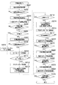
図2は、図1の熱昇華型プリンタによって実行される印刷処理の手順を示すフローチャートである。 FIG. 2 is a flowchart showing the procedure of the printing process executed by the thermal sublimation printer of FIG.
図1、図2に基づいて一連の印刷動作について説明する。尚、非印刷時は、プラテンローラ303は非圧着状態にある。 A series of printing operations will be described with reference to FIGS. Note that the platen roller 303 is in a non-compression state during non-printing.
ステップS201では、印刷用紙101を搬送経路109に送り出し、紙搬送を開始する。この状態を図1(a)に示す。(a)において、(a)−1は正面図、(a)−2は側面図である(以下の符号、及び図5、図7でも同様)。
In step S201, the
ステップS202では、印刷用紙101が紙先端検出センサ108で検出状態になるのを待つ。ステップS203では、紙先端検出センサ108が紙先端検出状態になり印刷用紙搬送を停止する(図1(b))。この紙先端検出位置を基準として以後の印刷用紙搬送が行われる。
In step S202, the process waits for the
ステップS204では、印刷用紙101の逆搬送を開始する。これはグリップローラ対104でグリップされる位置ができるだけ印刷用紙101の紙先端に近い方が最後に切断する印刷用紙の量が少なくて済むためである。
In step S204, reverse conveyance of the
逆搬送量は、紙先端検出センサ108とグリップローラ対104の位置関係及び検出精度からの設計値で決定されるものであり、印刷用紙101がグリップローラ対104から外れないと言う制約を持つ。
The reverse conveyance amount is determined by a design value based on the positional relationship between the paper leading
ステップS205では、印刷用紙101の逆搬送完了を待つ。以降、印刷操作を実行するが、ここで昇華型プリンタの原理について説明する。
In step S205, completion of reverse conveyance of the
熱昇華型プリンタでは、副走査方向に、不図示のステッピングモータによりグリップローラ対104を駆動する。そして、印刷用紙101を搬送しながら、主走査方向に並べられたサーマルヘッド106の1ピクセル中の加熱回数によりインクリボン105のインクを印刷用紙101上に昇華させ諧調表現を行う。
In the thermal sublimation printer, the
インクリボン105は、不図示のリボンフィードモータにより印刷用紙101の搬送と同時に巻き上げられる。搬送経路109方向に紙搬送が行われ、印刷が行われるとするとインクリボン105の供給側105aからインクリボン105が供給され、サーマルヘッド106により昇華されて巻き取り側105bにインクリボン105が巻き上げられる。
The
図3は、図1の熱昇華型プリンタにおける印刷用紙の搬送方向(副走査方向)とサーマルヘッド(主走査方向)との関係を示す図である。 FIG. 3 is a diagram showing the relationship between the printing paper conveyance direction (sub-scanning direction) and the thermal head (main scanning direction) in the thermal sublimation printer of FIG.
印刷に先立ち、インクリボン105の先頭検出が行われる。インクリボン105はイエロー、マゼンタ、シアン、オーバーコートの順に配置され、イエローだけが多色と異なったマーカーが付加されている。
Prior to printing, the leading edge of the
そのため、印刷に当たっては最初にイエローのマーカーサーチを行い、先頭色を確定する必要がある。イエロー以外の色は同じマーカーを有しているので順次サーチを繰り返せば良い。 Therefore, when printing, it is necessary to first perform a yellow marker search to determine the leading color. Since colors other than yellow have the same marker, the search may be repeated sequentially.
副走査方向への走査が終了すると、印刷用紙101を副走査開始位置まで戻し、次色の走査を始める。副走査方向への走査をイエロー、マゼンタ、シアンの3色繰り返し、最後にオーバーコートを行い、印刷を完了する。
When scanning in the sub-scanning direction is completed, the
ステップS206では、イエロー印刷であるかどうかの判定を行う(図1(c))。印刷色がイエローであった場合、ステップS209で、イエロー用のリボンマーカーサーチが実行される。 In step S206, it is determined whether or not yellow printing is performed (FIG. 1C). If the print color is yellow, a ribbon marker search for yellow is executed in step S209.
印刷色がイエローでない場合は、少なくとも1色印刷が終了しているので、印刷用に印刷用紙101を搬送したステップ分、印刷用紙101を逆搬送し、イエロー印刷開始と同じ位置に戻す動作が発生する。ステップS207で、印刷用紙101の逆搬送を開始する。
If the print color is not yellow, printing of at least one color has been completed. Therefore, an operation occurs in which the
ステップS208では、印刷用紙逆搬送の完了を待つ。印刷用紙101が印刷開始位置に戻った時点で、ステップS210で、次色のマーカーサーチを開始する。ステップS211では、イエローマーカー及びイエロー以外の色のマーカーサーチの完了を待つ。
In step S208, the process waits for completion of reverse printing paper conveyance. When the
リボンマーカーの検出が完了すると、ステップS212で、プラテンローラ103を上方に押し上げ、サーマルヘッド103、インクリボン105、印刷用紙101、プラテンローラ103を圧着させる(図1(d))。
When the detection of the ribbon marker is completed, in step S212, the
ステップS213では、印刷に当たりインクリボン105を巻き上げ、印刷用紙101の搬送、サーマルヘッド106の通電を開始して印刷を開始する。ステップS214では印刷用紙101の副操作方向への印刷搬送の完了(1色印刷の完了)を待つ。
In step S213, the
ステップS215では、1色印刷の完了に伴い、サーマルヘッド106への通電、印刷用紙101の搬送、インクリボン105の巻き上げを停止する。ステップS216では、プラテンローラ103を圧着状態から下方へ移動させて圧着状態の解除を行う(図1(e))。
In step S215, along with the completion of one-color printing, energization of the
ステップS217では、オーバーコート(OC)印刷の完了かどうかを判定する。オーバーコートで無かった場合は、次色の印刷があるためステップS206へ戻る。オーバーコートであった場合は、印刷処理を終了し、印刷用紙101から印刷した印刷物の切断処理を行う。
In step S217, it is determined whether overcoat (OC) printing is completed. If there is no overcoat, the process returns to step S206 because the next color is printed. If it is overcoat, the printing process is terminated, and the printed material printed from the
ステップS218では、印刷用紙101の先端部の切断を行うために、印刷用紙101の搬送を開始する。ステップS219では、印刷完了時の紙先端位置と切断装置110の位置までの設計値に基づき、印刷用紙101を切断位置まで搬送し、印刷用紙搬送の終了を待つ。ステップS220では、印刷用紙101の先端部切断を実行する(図1(f))。
In step S218, the conveyance of the
ステップS221では、印刷用紙101の後端部の切断を行うために、印刷物の終端まで印刷用紙101の搬送を開始する。ステップS222では、印刷用紙搬送の終了を待つ。ステップS223では、印刷用紙101から印刷物後端部の切断を実行する(図1(g))。
In step S221, in order to cut the trailing edge of the
最後に、切断装置110まで搬送された印刷用紙101をステップS224、ステップS225で、逆搬送して給紙位置まで印刷用紙101の紙先端部を戻して一連の印刷動作を終了する(図1(a))。
Finally, in steps S224 and S225, the
以上説明した様に、本発明では、印刷用紙101の先端を検出した時点からの紙搬送距離をステッピングモータのステップ数として距離を管理している。そのため、サーマルヘッド106の書き出し位置と印刷用紙101の先端までの距離、印刷用紙101の先端と切断装置110との距離が、組み立て精度等でばらつきが大きいと印刷物に欠けが生じてしまう。
As described above, in the present invention, the distance is managed using the paper transport distance from the time when the leading edge of the
図4は、図1の熱昇華型プリンタで得られる印刷物を示す図である。 FIG. 4 is a view showing a printed matter obtained by the thermal sublimation printer of FIG.
理想的な印刷物(画像)を(a)−1、(a)−2に示す。縁有り画像、縁無し画像とも画像重心と印刷用紙101の中心が一致している。サーマルヘッド106の書き出し位置と印刷用紙101の紙先端との距離が大きい場合の印刷物を(b)−1、(b)−2に示す。画像重心が下端にずれ、縁有り画像では縁の太さが不均一になる。縁有り画像では画像下端が印刷領域からはみ出してしまっている。
Ideal prints (images) are shown in (a) -1 and (a) -2. The center of gravity of the image and the center of the
(b)−1、(b)−2の逆で、サーマルヘッド106の書き出し位置と印刷用紙101の先端の距離が短い場合は、(c)−1、(c)−2に示す様な画像出力となる。これを校正するには機器毎の調整作業が発生する。
In the opposite of (b) -1 and (b) -2, when the distance between the writing position of the
よって、本発明では、搬送経路の調整動作について着目し、その調整方法について開示する。
(第1の実施の形態)
図5は、本発明の第1の実施の形態に係る熱昇華型プリンタの構成を示す図である。
Therefore, in the present invention, attention is paid to the adjustment operation of the conveyance path, and the adjustment method is disclosed.
(First embodiment)
FIG. 5 is a diagram showing the configuration of the thermal sublimation printer according to the first embodiment of the present invention.
具体的には、図1に示した構成において、印刷開始位置検出センサ107を搬送経路109上に設置したものである。この印刷開始位置検出センサ107も前述した様に、不図示のMPUにより監視されている。
Specifically, in the configuration shown in FIG. 1, the print start
図6は、図5の熱昇華型プリンタ及び後述する図7の熱昇華型プリンタによって実行される搬送量補正処理の手順を示すフローチャートである。 FIG. 6 is a flowchart showing a procedure of a conveyance amount correction process executed by the heat sublimation printer of FIG. 5 and the heat sublimation printer of FIG. 7 described later.
図5、図6に基づいて一連の印刷動作について説明する。 A series of printing operations will be described with reference to FIGS.
図6において、ステップS601では、給紙ローラ対102により印刷用紙101の給紙が開始される(図5(a))。ステップS602では、所定位置において、印刷用紙101の先端を紙先端検出センサ108が検出するのを待つ。紙先端検出センサ108が印刷用紙101の先端を検出すると、ステップS603で、印刷用紙101搬送を停止する(図5(b))。
In FIG. 6, in step S601, feeding of the
ステップS604で、印刷用紙101を逆方向に搬送開始する。逆搬送量は紙先端検出センサ108とグリップローラ対104の位置関係及び検出精度からの設計値で決定される固定値であり、印刷用紙101がグリップローラ対104から外れないと言う制約を持つ。ここで、グリップローラ対104は、印刷用紙101の搬送方向の最下流側に位置する。
In step S604, the
図5(b)には、逆搬送量をSB、紙先端検出センサ108の検出した紙先端と印刷開始位置検出センサ107の検出位置までのステップ数をSLとして示す。ステップS605で逆搬送の終了を待ち、終了すると、ステップS606で、不図示のMPUはRAM上に配置された計測用カウンタ1をリセットし、ステップS607で、リボンマーカーのサーチを行う。
FIG. 5B shows the reverse transport amount as SB, and the number of steps from the paper leading edge detected by the paper leading
ステップS608で、リボンマーカーサーチの完了を待ち、リボンマーカーサーチが完了すると、ステップS609で、プラテンローラ103を押し上げて圧着状態を作り、ステップS610で、印刷開始位置の検出を開始する。
In step S608, the completion of the ribbon marker search is awaited. When the ribbon marker search is completed, in step S609, the
ステップS611では、インクリボン105の巻き上げ、印刷用紙101の搬送、サーマルヘッド106の通電を開始して印刷動作を開始する(図5(c))。ここで、印刷を開始するのは、ヘッド書き出し位置計測用の印刷先端マーカー120を印刷するためである。
In step S611, winding of the
図5(d)の印刷先端マーカー120に示す様に、印刷開始位置に印刷を行い、搬送経路109の後段に位置する印刷開始位置検出センサ107でこの印刷先端マーカー120の書き出し位置を検出する(ステップS612)。図5(d)中の紙先端と印刷開始位置までのステップ数をSSとして示す。
As shown in the print leading
印刷開始位置検出センサ107は、フォトリフレクタ等のフォトセンサでセンサ側の光源で発光してその反射光を電気信号に変換して対象物の有無を検出する。
The print start
印刷先端マーカー120を印刷した印刷用紙101を前方に印刷搬送していくと、印刷開始位置検出センサ107に印刷用紙101が達していない場合は、印刷用紙101による反射が発生しないのでセンサ出力は発生しない。印刷用紙101が印刷位置検出センサ107に達すると、印刷用紙101による反射が発生し、センサ出力が発生する。
When the
更に、印刷用紙101を前方に搬送すると、やがて印刷先端マーカー120が印刷開始位置検出センサ107に達する。印刷先端マーカー120は、黒色とすると反射光がなくなりセンサ出力が発生しなくなる。この様に、印刷開始位置検出センサ107の出力を監視して印刷開始位置を特定することができる。
When the
また、図5(c)の位置からグリップローラ対104を駆動するステッピングモータのステップ数を印刷開始位置検出までカウントしておくことで、印刷用紙101の先端から印刷開始位置までの距離に換算することができる。不図示のMPUはこのステップ数カウントを記憶しておくことが可能である。
Further, by counting the number of steps of the stepping motor that drives the
ステップS613では、これを計測カウンタ1の計測値として記憶する。以下の演算により、計測カウンタ1に記憶されているステップ数から、紙先端から印刷開始位置のステップ数を算出することができる。
SB:紙先端検出からの逆搬送ステップ数
SL:紙先端検出位置から印刷開始位置検出センサ位置までのステップ数
SS:紙先端から印刷開始位置までのステップ数
計測カウンタ1(のカウント数)=SB+SL+SS
SS=計測カウンタ1−(SB+SL)
ステップS614では、印刷領域の印刷終了を待つ。印刷が終了すると、ステップS615で、プラテンローラ103を下方に移動させ圧着状態を解除する。ステップS617では、印刷完了後、印刷先端マーカー120が切断装置110を確実に越える位置まで紙搬送を行う。この搬送量は、印刷完了時の紙先端位置と印刷開始位置及び、切断装置位置までの設計値、組み立て精度に基づいて設定される固定値である。
In step S613, this is stored as a measurement value of the
SB: Number of reverse transport steps from paper leading edge detection SL: Number of steps from paper leading edge detection position to print start position detection sensor position SS: Step
SS =
In step S614, the process waits for the printing area to be printed. When printing is completed, in step S615, the
ステップS618で、印刷用紙101の印刷先端マーカー120が切断装置110を超えた位置で切断処理が行われる(図5(e))。ステップS619で、不図示のMPUはRAM上に配置された計測カウンタ2をリセットする。これは、切断装置110から紙先端検出位置までの距離を計測するためである。
In step S618, a cutting process is performed at a position where the printing leading
印刷用紙101に対し、切断処理を実行したことにより、印刷用紙101の紙先端は、切断装置110上となる。ステップS620では、印刷用紙101を、グリップローラ対104を駆動するステッピングモータのステップ数をカウントアップしながら逆搬送して、紙先端検出センサ108が紙先端検出しなくなる状態になったところで逆搬送を停止する。
By executing the cutting process on the
ステップS621では、紙搬送を開始して、再び、紙先端検出センサ108が紙先端検出を行う状態にする。このとき、グリップローラ対104は反対に駆動されるため、計測カウンタ2はカウントダウンする。
In step S621, paper conveyance is started, and the paper leading
ステップS622では、紙先端検出センサ108が再び印刷用紙101の紙先端を検出するのを待つ。紙先端を検出すると、ステップS623で、計測カウンタ2の内容を計測値として記憶する。先に説明した計測カウンタ1は紙先端から印刷開始位置までのステップ数、計測カウンタ2は紙先端(紙先端検出センサ108)から切断装置110までのステップ数となる。
SC:切断装置から紙先端検出センサ108までのステップ数
SC=計測カウンタ2(のカウント数)
ステップS623では、S622で計測した紙先端検出センサ108から切断装置110までのステップ数を記録する。
In step S622, it waits for the paper leading
SC: number of steps from the cutting device to the paper leading edge detection sensor SC = measurement counter 2 (count number)
In step S623, the number of steps from the paper leading
ステップS624では、S613で記憶した紙先端から印刷開始位置のステップ数に基づいて印刷用紙101先端と印刷開始位置とが設計値となる様に、以下の処理を行う。即ち、印刷処理時のS204(図1(c))における紙検出位置から印刷用紙101を逆搬送するステップ数に補正を加え、次回以降の印刷実行時から補正を有効にする。
In step S624, the following processing is performed so that the leading edge of the
この補正により、紙先端検出センサ108とサーマルヘッドの組み立て設置時のばらつきを吸収することができ、印刷用紙先端と印刷開始位置が一定量に設定される。
By this correction, it is possible to absorb variations in the assembly and installation of the paper leading
ステップS625では、印刷処理のS218、S221における搬送ステップ数を、紙S623で記録した紙先端検出センサ108から切断装置110までのステップ数に基づいて補正し、次回の印刷実行時から補正を有効にする。
In step S625, the number of transport steps in S218 and S221 of the printing process is corrected based on the number of steps from the paper leading
図2、図6のフローチャートは、請求項に記載した、第1の記録手段、搬送制御手段、駆動制御手段、第2の記録手段として機能する。 The flowcharts of FIGS. 2 and 6 function as the first recording unit, the conveyance control unit, the drive control unit, and the second recording unit described in the claims.
以上の操作により、切断装置110までの搬送量が補正され、切断装置の組み立て設置時のばらつきを吸収し、印刷用紙の切断位置が適正に設定される。
With the above operation, the conveyance amount to the
以上の動作を不図示のROMにプログラムとして格納しておけば、特別な装置が無くても必要な時に切断位置の補正を実行することができる。 If the above operation is stored as a program in a ROM (not shown), the cutting position can be corrected when necessary without a special device.
このような搬送量補正処理は、印刷装置の工場出荷時や印刷装置の初期化時、また、切断装置の取り替え時に行うと効果的である。印刷装置の工場出荷時や印刷装置の初期化時、また、切断装置の取り替え時に、印刷用紙先端から印刷開始位置までの搬送距離の情報や、紙先端検出センサ108から切断位置までの搬送量を記録しておき、印刷時に記録した情報に基づいて補正してもよい。
Such a conveyance amount correction process is effective when it is performed at the time of factory shipment of the printing apparatus, when the printing apparatus is initialized, or when the cutting apparatus is replaced. When the printing device is shipped from the factory, when the printing device is initialized, or when the cutting device is replaced, information on the transport distance from the front end of the printing paper to the print start position, and the transport amount from the paper front
本実施の形態では、S613において算出した紙先端から印刷開始位置のステップ数に基づいて印刷処理時のS204における逆搬送ステップ数を補正することで、紙先端検出センサ108とサーマルヘッドの組み立て設置時のばらつきを吸収した。しかし、S204に置ける逆補正ステップ数は補正せずに、印刷処理のS218、S221における搬送ステップ数を、S623で記録したステップ数とS613において記録したステップ数に基づいて補正してもよい。これにより、印刷処理のS218、S221における搬送ステップ数を補正するだけで、紙先端検出センサ、サーマルヘッド、切断装置の組み立て設置時のばらつきを吸収し印刷用紙の切断位置が適正に設定される。
(第2実施の形態)
図7は、本発明の第2の実施の形態に係る熱昇華型プリンタの構成を示す図である。
In the present embodiment, the number of reverse transport steps in S204 at the time of printing processing is corrected based on the number of steps from the paper leading edge calculated in S613 to the time of assembly and installation of the paper leading
(Second Embodiment)
FIG. 7 is a diagram showing a configuration of a thermal sublimation printer according to the second embodiment of the present invention.
第1の実施の形態との違いは、図5における、紙先端検出センサと印刷開始位置検出センサを1つのセンサで兼用したことである。即ち、第1の実施の形態で、紙先端検出に用いていたスイッチ形式のセンサをフォトリフレクタタイプのものとして印刷開始位置検出センサと兼用したものである。以下に図5と対比して説明する。 The difference from the first embodiment is that the paper leading edge detection sensor and the print start position detection sensor in FIG. 5 are combined into one sensor. That is, in the first embodiment, the switch type sensor used for detecting the leading edge of the paper is used as a photo reflector type and also serves as a print start position detection sensor. This will be described below in comparison with FIG.
図7における紙先端/印刷開始位置検出センサ115は、図5における印刷開始位置検出センサ107と紙先端検出センサ108を同一のセンサで兼用したものである。センサを兼用したことにより、図5で示した紙先端検出センサ108と印刷開始位置検出センサ107との設置距離を意識することなく計測動作を行うことができる。
The paper leading / printing start
以下に、図6のフローチャートを用いて図7の熱昇華型プリンタの動作を説明する。 The operation of the thermal sublimation printer of FIG. 7 will be described below using the flowchart of FIG.
ステップS601では、給紙ローラ対102により印刷用紙101の給紙が開始される(図7(a))。ステップS602では、紙先端/印刷開始位置検出センサ115が印刷用紙101の先端検出状態になるのを待つ。
In step S601, the feeding of the
紙先端/印刷開始位置検出センサ115が印刷用紙101の先端を検出すると、ステップS603で、印刷用紙搬送を停止する(図7(b))。ステップS604で、印刷用紙101を逆方向に搬送開始する。
When the leading edge / printing start
逆搬送量は、紙先端/印刷開始位置検出センサ115とグリップローラ対104の位置関係及び検出精度からの設計値で決定される固定値であり、印刷用紙101がグリップローラ対104から外れないと言う制約を持つ。図7(b)には逆搬送量SBとして示す。
The reverse transport amount is a fixed value determined by a design value based on the positional relationship between the paper leading edge / print start
ステップS605で、逆搬送の終了を待ち、終了すると、ステップS606で、不図示のMPUはRAM上に配置された計測用カウンタ1をリセットし、ステップS607で、リボンマーカーのサーチを行う。
In step S605, the process waits for the end of reverse conveyance. When the MPU is not completed, the MPU (not shown) resets the
ステップS608で、リボンマーカーサーチの完了を待ち、リボンマーカーサーチが完了すると、ステップS609で、プラテンローラ103を押し上げて圧着状態を作り、ステップS610で、印刷開始位置の検出を開始する。
In step S608, the completion of the ribbon marker search is awaited. When the ribbon marker search is completed, in step S609, the
ステップS611では、インクリボン105の巻き上げ、印刷用紙101の搬送、サーマルヘッド106の通電を開始して印刷動作を開始する(図7(c))。ここで印刷を開始するのは、ヘッド書き出し位置計測用の印刷先端マーカー120を印刷するためである。
In step S611, winding of the
図7(d)の印刷先端マーカー120に示す様に、印刷開始位置に印刷を行い紙先端/印刷開始位置検出センサ115で、この印刷先端マーカー120の書き出し位置を検出する。紙先端/印刷開始位置検出センサ115は、フォトリフレクタ等のフォトセンサで、センサ側の光源で発光してその反射光を電気信号に変換して対象物の有無を検出する。
7D, printing is performed at the printing start position, and the paper leading / printing start
印刷先端マーカー120を印刷した印刷用紙101を前方に印刷搬送していくと、紙先端/印刷開始位置検出センサ115に印刷用紙101が達していない場合は、印刷用紙101による反射が発生しないのでセンサ出力は発生しない。
When the
印刷用紙101が紙先端/印刷位置検出センサ115に達すると、印刷用紙101による反射が発生し、センサ出力が発生する。更に、印刷用紙101を前方に搬送すると、やがて印刷先端マーカー120が紙先端/印刷開始位置検出センサ115に達する。印刷先端マーカー120は、黒色とすると反射光がなくなりセンサ出力が発生しなくなる。
When the
この様に、紙先端/印刷開始位置検出センサ115の出力を監視して紙先端位置、印刷開始位置を特定することができる。また、図7(c)の位置からグリップローラ対104を駆動するステッピングモータのステップ数を印刷開始位置検出までカウントしておくことで、印刷用紙101の先端から印刷開始位置までの距離に換算することができる。不図示のMPUはこのステップ数カウントを記憶しておくことが可能である。
In this manner, the output of the paper leading edge / printing start
ステップS613では、これを計測カウンタ1の計測値として記憶する。本実施の形態においては、紙先端/印刷開始位置検出センサ115が、紙先端検出センサ108と印刷開始位置検出センサ107を兼用しているため、紙先端検出センサ108と印刷開始位置検出センサ107の位置関係の補正の必要がない。
In step S613, this is stored as a measurement value of the
以下の演算により、計測カウンタ1に記憶されているステップ数から紙先端/印刷開始位置検出センサ115から印刷開始位置のステップ数を算出することができる。
SB:紙先端検出(紙先端/印刷開始位置検出センサ115)からの逆搬送ステップ数
SS:紙先端/印刷開始位置検出センサ115から印刷開始位置までのステップ数
計測カウンタ1=SB+SS
SS=計測カウンタ1−SB
ステップS614では、印刷領域の印刷終了を待つ。印刷が終了すると、ステップS615で、プラテンローラ103を下方に移動させ圧着状態を解除する。ステップS617では、印刷完了後、印刷先端マーカー120が切断装置110を確実に越える位置まで紙搬送を行う。この搬送量は、印刷完了時の紙先端位置と印刷開始位置及び、切断装置110の位置までの設計値、組み立て精度に基づいて設定される固定値である。
From the number of steps stored in the
SB: Number of reverse transport steps from the paper leading edge detection (paper leading edge / printing start position detection sensor 115) SS: Step
SS = Measurement counter 1-SB
In step S614, the process waits for the printing area to be printed. When printing is completed, in step S615, the
ステップS618で、印刷用紙101の印刷先端マーカー120が切断装置110を超えた位置で切断処理が行われる(図7(e))。ステップS619で、不図示のMPUはRAM上に配置された計測カウンタ2をリセットする。これは、切断装置110から紙先端/印刷開始位置検出センサ115までの距離を計測するためである。
In step S618, a cutting process is performed at a position where the printing leading
印刷用紙101に対し切断処理を実行したことにより、印刷用紙101の紙先端は切断装置110上となる。ステップS620では、印刷用紙101を、グリップローラ対104を駆動するステッピングモータのステップ数をカウントアップしながら逆搬送して紙先端/印刷開始位置検出センサ115が紙先端検出しなくなる状態になったところで逆搬送を停止する。
By executing the cutting process on the
ステップS621では、紙搬送を開始して、再び、紙先端/印刷開始位置検出センサ115を紙先端検出状態にする。ステップS622では、紙先端/印刷開始位置検出センサ115が再び印刷用紙101の紙先端を検出するのを待つ。このとき、グリップローラ対104は反対に駆動されるため、計測カウンタ2はカウントダウンする。
In step S621, paper conveyance is started and the paper leading / printing start
紙先端を検出すると、ステップS623、計測カウンタ2の内容を計測値として記憶する。先に説明した計測カウンタ1は、紙先端から印刷開始位置までのステップ数、計測カウンタ2は、紙先端(紙先端/印刷開始位置検出センサ115)から切断装置110までのステップ数となる。
SC:切断装置110から紙先端検出位置(紙先端/印刷開始位置検出センサ115)までのステップ数
SC=計測カウンタ2
ステップS623では、S622で計測した紙先端検出位置(紙先端/印刷開始位置検出センサ115)から切断装置110までのステップ数を記録する。
When the leading edge of the paper is detected, the content of the
SC: number of steps from the
In step S623, the number of steps from the paper leading edge detection position (paper leading edge / printing start position detection sensor 115) measured in S622 to the
ステップS624では、S613で記憶した紙先端から印刷開始位置のステップ数に基づいて印刷用紙101先端と印刷開始位置とが設計値となる様に、印刷処理時のS204(図1(c))における紙検出位置から印刷用紙101を逆搬送するステップ数に補正を加え、次回以降の印刷実行時から補正を有効にする。
In step S624, based on the number of steps from the paper leading edge stored in S613 to the printing start position, the leading edge of the
この補正により、紙先端/印刷開始位置検出センサ115とサーマルヘッドの組み立て設置時のばらつきを吸収することができ、印刷用紙先端と印刷開始位置が一定量に設定される。
By this correction, it is possible to absorb variations at the time of assembling and installing the paper leading edge / printing start
ステップS625では、印刷処理のS218、S221における搬送ステップ数を、紙S623で記録した紙先端/印刷開始位置検出センサ115から切断装置110までのステップ数に基づいてに補正し、次回の印刷実行時から補正を有効にする。
In step S625, the number of transport steps in S218 and S221 of the printing process is corrected based on the number of steps from the paper leading edge / print start
以上の操作により、切断装置110までの搬送量が補正され、切断装置の組み立て設置時のばらつきを吸収し、印刷用紙の切断位置が適正に設定される。
With the above operation, the conveyance amount to the
このような搬送量補正処理は、印刷装置の工場出荷時や印刷装置の初期化時、また、切断装置の取り替え時に行うと効果的である。印刷装置の工場出荷時や印刷装置の初期化時、切断装置の取り替え時に、印刷用紙先端から印刷開始位置までの搬送距離の情報や紙先端/印刷開始位置検出センサ115から切断位置までの搬送量を記録しておき、印刷時に記録した情報に基づいて補正してもよい。
Such a conveyance amount correction process is effective when it is performed at the time of factory shipment of the printing apparatus, when the printing apparatus is initialized, or when the cutting apparatus is replaced. When the printer is shipped from the factory, when the printer is initialized, or when the cutting device is replaced, information on the transport distance from the front end of the print paper to the print start position and the transport amount from the paper front end / print start
本実施の形態では、S613において算出した紙先端から印刷開始位置のステップ数に基づいて印刷処理時のS204における逆搬送ステップ数を補正することで、紙先端/印刷開始位置検出センサ115とサーマルヘッドの組み立て設置時のばらつきを吸収した。
In the present embodiment, the paper leading edge / printing start
しかし、S204に置ける逆補正ステップ数は補正せずに、印刷処理のS218、S221における搬送ステップ数を、S623で記録したステップ数とS613において記録したステップ数に基づいて補正してもよい。これにより、印刷処理のS218、S221における搬送ステップ数を補正するだけで、紙先端/印刷開始位置検出センサ、サーマルヘッド、切断装置の組み立て設置時のばらつきを吸収することができる。 However, the reverse correction step number that can be placed in S204 may be corrected, and the transport step number in S218 and S221 of the printing process may be corrected based on the step number recorded in S623 and the step number recorded in S613. As a result, it is possible to absorb variations in the assembly and installation of the paper leading edge / print start position detection sensor, the thermal head, and the cutting device only by correcting the number of transport steps in S218 and S221 of the printing process.
Claims (2)
ロール紙に画像を印刷するための印刷ヘッドと、
前記ロール紙を切断するための切断手段と、
前記ロール紙を搬送させるための搬送手段と、
前記ロール紙の搬送経路中の所定位置において前記ロール紙の先端を検出する検出手段と、
前記切断手段によりロール紙を切断した後に前記検出手段の方向に前記ロール紙を搬送させて前記ロール紙の先端を前記検出手段で検出することにより、前記検出手段から前記切断手段までの搬送量を計測し、前記検出手段から前記切断手段までの搬送量に関する情報を記録すると共に、前記印刷装置の初期化時に前記検出手段から前記切断手段までの搬送量に関する情報を記録する第1の記録手段と、
前記第1の記録手段により記録された前記検出手段から前記切断手段までの搬送量に関する情報に基づいて、前記切断手段までのロール紙の搬送量を補正して前記搬送手段を駆動させる搬送制御手段と、
前記検出手段が前記ロール紙の先端を検出した位置に基づいて印刷開始位置を決定し、印刷開始位置から印刷するために前記印刷ヘッドを駆動制御する駆動制御手段と、
前記印刷ヘッドによりロール紙に印刷されたマーカーを前記検出手段が検出することにより前記ロール紙の先端から印刷開始位置までの搬送距離を計測し、前記ロール紙の先端から印刷開始位置までの搬送量に関する情報を記録する第2の記録手段とを有し、
前記搬送制御手段は、前記第2の記録手段により記録された前記ロール紙の先端から印刷開始位置までの搬送量に関する情報に基づいて、前記ロール紙を切断する際の前記ロール紙の搬送量を補正して前記搬送手段を駆動させることを特徴とする印刷装置。 A printing device for printing an image on roll paper,
A print head for printing an image on roll paper;
Cutting means for cutting the roll paper;
Conveying means for conveying the roll paper;
Detecting means for detecting the leading edge of the roll paper at a predetermined position in the transport path of the roll paper;
After the roll paper is cut by the cutting means, the roll paper is conveyed in the direction of the detection means, and the leading end of the roll paper is detected by the detection means, thereby reducing the conveyance amount from the detection means to the cutting means. A first recording means for measuring and recording information relating to the conveyance amount from the detection means to the cutting means, and recording information relating to the conveyance amount from the detection means to the cutting means at the time of initialization of the printing apparatus ; ,
A conveyance control unit that corrects the conveyance amount of the roll paper to the cutting unit and drives the conveyance unit based on information on the conveyance amount from the detection unit to the cutting unit recorded by the first recording unit. When,
A drive control unit that determines a print start position based on a position at which the detection unit detects the leading edge of the roll paper, and drives and controls the print head to print from the print start position;
The detection unit detects the marker printed on the roll paper by the print head, thereby measuring the transport distance from the leading edge of the roll paper to the printing start position, and the transport amount from the leading edge of the roll paper to the printing start position. A second recording means for recording information on
The conveyance control unit is configured to determine a conveyance amount of the roll paper when cutting the roll paper based on information on a conveyance amount recorded from the leading end of the roll paper to a printing start position recorded by the second recording unit. A printing apparatus that corrects and drives the conveying means .
Priority Applications (1)
| Application Number | Priority Date | Filing Date | Title |
|---|---|---|---|
| JP2008124614A JP5247227B2 (en) | 2008-05-12 | 2008-05-12 | Printing device |
Applications Claiming Priority (1)
| Application Number | Priority Date | Filing Date | Title |
|---|---|---|---|
| JP2008124614A JP5247227B2 (en) | 2008-05-12 | 2008-05-12 | Printing device |
Publications (2)
| Publication Number | Publication Date |
|---|---|
| JP2009274218A JP2009274218A (en) | 2009-11-26 |
| JP5247227B2 true JP5247227B2 (en) | 2013-07-24 |
Family
ID=41440097
Family Applications (1)
| Application Number | Title | Priority Date | Filing Date |
|---|---|---|---|
| JP2008124614A Expired - Fee Related JP5247227B2 (en) | 2008-05-12 | 2008-05-12 | Printing device |
Country Status (1)
| Country | Link |
|---|---|
| JP (1) | JP5247227B2 (en) |
Families Citing this family (4)
| Publication number | Priority date | Publication date | Assignee | Title |
|---|---|---|---|---|
| JP2013028004A (en) * | 2011-07-27 | 2013-02-07 | Canon Inc | Recorder and method for controlling conveyance of recording medium |
| JP5991829B2 (en) * | 2012-03-16 | 2016-09-14 | 三菱電機株式会社 | Thermal printer device |
| JP7031390B2 (en) * | 2018-03-13 | 2022-03-08 | 株式会社リコー | Image processing equipment, printable range detection method and program |
| JP7396803B2 (en) | 2019-03-01 | 2023-12-12 | 株式会社きもと | Lens spacer, laminated light shielding member, light shielding ring, lens unit and camera module using the same |
Family Cites Families (1)
| Publication number | Priority date | Publication date | Assignee | Title |
|---|---|---|---|---|
| JP2004249476A (en) * | 2003-02-18 | 2004-09-09 | Seiko Epson Corp | Recording device, liquid ejecting device |
-
2008
- 2008-05-12 JP JP2008124614A patent/JP5247227B2/en not_active Expired - Fee Related
Also Published As
| Publication number | Publication date |
|---|---|
| JP2009274218A (en) | 2009-11-26 |
Similar Documents
| Publication | Publication Date | Title |
|---|---|---|
| US6624876B2 (en) | Method of printing calibration pattern and printer | |
| JP5082755B2 (en) | Recording medium detection method and label printer | |
| KR20050069458A (en) | Image aligning method of duplex image forming printer | |
| JP2004059192A (en) | Printer | |
| CN100430231C (en) | Thermal printer and printing method | |
| US7830564B2 (en) | Method of obtaining correction value of optical sensor and recording apparatus | |
| JP5247227B2 (en) | Printing device | |
| WO2011064907A1 (en) | Validation device | |
| KR20050114884A (en) | Method of distinguishing thermal media | |
| JP5181909B2 (en) | Printer reprint control method and printer | |
| JP2005219311A (en) | Image forming apparatus and density unevenness correction method | |
| US20080025781A1 (en) | Printer and method for controlling the printer | |
| CN100364777C (en) | Method of printing heat-sensitive media by registering images | |
| JP2006130857A (en) | Recording device | |
| JP3207344B2 (en) | Serial dot printer and its operation control method | |
| JP2010023387A (en) | Method for cutting recording paper in printer and printer | |
| JP2010023386A (en) | Method for cutting recording paper in printer and printer | |
| CN100379570C (en) | Method of printing thermal sensitive media by registering images | |
| CN1706656A (en) | Method of printing on thermal media | |
| KR20050110488A (en) | Method of measuring slip of thermal printer | |
| JP5609999B2 (en) | Printer reprint control method and printer | |
| US20060012665A1 (en) | Print media and photo printer | |
| JP3886462B2 (en) | Printer transport control method and printer transport control method | |
| JP7669649B2 (en) | Printing device, method for determining width of printed medium, and program | |
| JP4473682B2 (en) | Printing device |
Legal Events
| Date | Code | Title | Description |
|---|---|---|---|
| A621 | Written request for application examination |
Free format text: JAPANESE INTERMEDIATE CODE: A621 Effective date: 20110502 |
|
| A977 | Report on retrieval |
Free format text: JAPANESE INTERMEDIATE CODE: A971007 Effective date: 20121129 |
|
| A131 | Notification of reasons for refusal |
Free format text: JAPANESE INTERMEDIATE CODE: A131 Effective date: 20121211 |
|
| A521 | Written amendment |
Free format text: JAPANESE INTERMEDIATE CODE: A523 Effective date: 20130129 |
|
| TRDD | Decision of grant or rejection written | ||
| A01 | Written decision to grant a patent or to grant a registration (utility model) |
Free format text: JAPANESE INTERMEDIATE CODE: A01 Effective date: 20130312 |
|
| A61 | First payment of annual fees (during grant procedure) |
Free format text: JAPANESE INTERMEDIATE CODE: A61 Effective date: 20130409 |
|
| FPAY | Renewal fee payment (event date is renewal date of database) |
Free format text: PAYMENT UNTIL: 20160419 Year of fee payment: 3 |
|
| LAPS | Cancellation because of no payment of annual fees |