JP5249860B2 - Heat dissipation fan - Google Patents
Heat dissipation fan Download PDFInfo
- Publication number
- JP5249860B2 JP5249860B2 JP2009134109A JP2009134109A JP5249860B2 JP 5249860 B2 JP5249860 B2 JP 5249860B2 JP 2009134109 A JP2009134109 A JP 2009134109A JP 2009134109 A JP2009134109 A JP 2009134109A JP 5249860 B2 JP5249860 B2 JP 5249860B2
- Authority
- JP
- Japan
- Prior art keywords
- fan
- electrical connection
- frame
- connection port
- substrate
- Prior art date
- Legal status (The legal status is an assumption and is not a legal conclusion. Google has not performed a legal analysis and makes no representation as to the accuracy of the status listed.)
- Expired - Fee Related
Links
Images




Landscapes
- Structures Of Non-Positive Displacement Pumps (AREA)
- Motor Or Generator Frames (AREA)
- Connection Of Motors, Electrical Generators, Mechanical Devices, And The Like (AREA)
Description
本発明は、放熱ファンに関するもので、特に電源接続線の組立作業がさらに簡単になる放熱ファンに係るものである。 The present invention relates to a heat dissipating fan, and more particularly to a heat dissipating fan that further facilitates assembly work of a power connection line.
従来の放熱ファンの構造として、通常としては電源接続線を有することにより、電源と外接して放熱ファンの作動に提供することができる。一般として、電源接続線の固定位置を妥当に処理して配置しなければならない。それによって、放熱ファンが実際の運転過程において電源接続線が緩んで脱落したり、放熱ファンに巻き込まれたりするのを有効に避けることにより、放熱ファンの正常な運転を維持することができる。また、現在市場でよく見られている各種の放熱ファンにとって言えば、その電源接続線は大体として全て相当な複雑な巻き付けによる固定方式を使用しなければならないため、組立作業において大変不便になる。 As a structure of a conventional heat radiating fan, usually, by having a power supply connection line, it can be provided for the operation of the heat radiating fan by circumscribing the power source. In general, the fixed position of the power connection line must be properly processed and arranged. As a result, it is possible to maintain normal operation of the heat dissipation fan by effectively avoiding the power supply connection line from loosening and dropping off or being caught in the heat dissipation fan in the actual operation process. In addition, for various types of heat dissipating fans that are often seen in the market today, the power supply connection lines generally have to use a considerably complicated winding fixing method, which is very inconvenient in assembly work.
例えば中華民国新型公告番号第502821号「ファンの線整理構造」(特許文献1)において、図11を参照すると、従来の放熱ファン70には線整理構造71が含まれ、線整理構造71には底部711、二個の側面支持部712、712と二個の止め板部713、713が含まれる。これにより、線整理構造71により線材(電源接続線)72を迂回の方式で底部711、側面支持部712および止め板部713の間に設置することができるようにしたものがある。
For example, in the new model number 502821 of the Republic of China “Fan Line Arrangement Structure” (Patent Document 1), referring to FIG. 11, the conventional
また、従来の放熱ファンの構造として、例えば中華民国公告番号第449682号「超薄型冷却ファンの構造」(特許文献2)では、図12、13に示すように、従来の放熱ファン80には框体81、ステータ座82、ファンホイール83と蓋板84が含まれる。框体81には収容室811および収容室811と連通する溝道812が形成される。ステータ座82は収容室811の内に設けられ、ステータ座82には電気的接続ポート821が設けられ、電気的接続ポート821は電源接続線822と接続するように形成される。ファンホイール83は回転自在にステータ座82に結合され、ファンホイール83には永久磁石831が形成される。蓋板84には凸板841が設けられ、蓋板84が框体81と結合した時、凸板841は対応するように溝道812に伸び入れるように形成される。これにより、電源接続線822の組立作業を行う時、電源接続線822の一端は溝道812の位置まで巻き付けられることができ、そして溝道812を経由して框体81の外部まで貫穿して伸び入れることができるため、電源と外接するのに便利になり、それから凸板841を利用して電源接続線822を押圧して固定するようにとしたものがある。
Further, as a structure of a conventional heat radiating fan, for example, in the public notice No. 449682 “Structure of an ultra-thin cooling fan” (Patent Document 2), as shown in FIGS. A
さらに、従来の放熱ファンの構造として、例えば中華民国新型公告番号第443435号「送風ファンの電線係止部材の構造改良」(特許文献3)では、図14に示すように、従来の放熱ファン90にはファン基座91が形成され、ファン基座91には側壁の間に隣接するコーナーにおいて導線溝911が設けられ、導線溝911は充填体92を組み立てるのに用いられる。これにより、放熱ファン90に形成される電線(すなわち電源接続線)93は導線溝911の位置まで巻く付けられ、それから導線溝911を経由してファン基座91の外部まで貫穿して伸び入れることができるため、電源と外接するのに便利になり、それから充填体92を利用して電線93を押圧して固定するようにとしたものがある。
Furthermore, as a structure of a conventional heat radiating fan, for example, in the new public notice number 443435 of the Republic of China “Structural improvement of a wire locking member of a blower fan” (Patent Document 3), as shown in FIG. A
上記のような中華民国新型公告番号第502821号に提示されている従来の放熱ファン70において、一般として次のような問題点を有している。従来の放熱ファン70において、線整理構造71は線材72に対して良好な固定効果を提供することができるが、実際に線材72を固定しようとする時、相変わらず線材72の一端を先ず放熱ファン70の下方を貫穿して外部まで延伸させてから、再び迂回による巻き線の方式を通じて線材72を順序よく底部711、側面支持部712と止め板部713の間に係止させなければならない。このように、線材72の組立作業の難度が増えてしまうという問題点があった。その他に、従来の放熱ファン70によれば、線材72を固定する構造としても相当に複雑であるため、全体の製造コストも相対的に高くなるという問題点があった。
The conventional
また、上記の中華民国公告番号第449682号に提示されている従来の放熱ファン80において、一般として次のような問題点を有している。従来の放熱ファン80において、溝道812によれば電源接続線822の一端を框体81の外部まで貫穿して伸び入れることができるが、ステータ座82の電気的接続ポート821は溝道812の方向に向いておらず、すなわち電気的接続ポート821から溝道812まで相変わらず一定の距離を有しており、そのため、電源接続線822を電気的接続ポート821に接続した後、相変わらず框体81の収容室811の内において一定の距離を事前に巻き付けて置かなければならず、そうすることによって溝道812を経由して框体81の外部まで貫穿して伸び入れることができるため、電源接続線822の巻き付けによる固定作業に難度が増えてしまい、さらに組立上において大変不便になるという問題点があった。また、框体81の収容室811の内において電源接続線822の巻き付けの距離が長過ぎると、放熱ファン80が実際に運転する時、電源接続線822がファンホイール83の中に巻き込まれやすくなるという問題点があった。
In addition, the conventional
また、上記放熱ファン80によれば、上述した巻き付けによる固定作業の難度が増えてしまうとともに、組立上において大変不便になるという問題点の他に、下記の問題点を有している。再び図13を参照すると、ステータ座82の電気的接続ポート821がファンホイール83の永久磁石831の下方に位置するように形成されるため、放熱ファン80の組立作業を終えた後、ファンホイール83の永久磁石831底縁からステータ座82までの間には充分な距離を有する間隔Dを保留しなければならず、上記間隔Dは電気的接続ポート821(例えば溶接点など)と電源接続線822を収容するのに用いられることにより、ファンホイール83が順調に回転して作動することができる。しかし、従来の放熱ファン80によれば、比較的大きい間隔Dを予め保留しなければならないため、放熱ファン80全体の軸方向の高さを有効に減らすことができないため、従来の放熱ファン80をさらに軽薄かつ小型化に設計することができないという問題点があった。
Moreover, according to the said
さらに、上記のような中華民国新型公告番号第443435号に掲示されている従来の放熱ファン90においては、一般として下記の問題点を有している。従来の放熱ファン90において、導線溝911はファン基座91が隣接する側壁の間のコーナーに設置ることにより、電線93の巻き線の距離の減少を図っているが、放熱ファン90によってファンホイール94が回転するのを駆動するためのステータ構造(図示せず)の電気的接続ポート(図示せず)は、導線溝911の方向に向いていないとの条件において、電線93が電気的接続ポートに接続された後、電線93は相変わらずファン基座91の内側に形成された空間において一定の距離を巻き付けなければならず、それによって導線溝911を経由してファン基座91の外部まで貫穿して伸び入れることができない。故に従来の放熱ファン90によれば、同様に電線93の巻き付けによる固定作業に難度が増えてしまい、さらに組立上において大変不便になるという問題点があった。このように、上記のような従来の放熱ファンの構造をさらに改良しなければならない。
Furthermore, the conventional
本発明はこのような問題点に鑑みて発明したものであって、その主な目的とするところは、従来の放熱ファンによる電源接続線の巻き付けの固定作業に難度が増えてしまうとともに、組立上において大変不便になるという問題点を解決することができる放熱ファンを提供することにある。 The present invention has been invented in view of such problems, and the main object of the present invention is to increase the difficulty in fixing the winding of the power connection line by a conventional heat radiating fan, and to improve the assembly. It is an object of the present invention to provide a heat dissipation fan that can solve the problem of inconvenience.
本発明の第二の目的は、全体の軸方向の高さを有効に低く抑えることができる放熱ファンを提供することにある。 The second object of the present invention is to provide a heat radiating fan capable of effectively reducing the overall axial height.
上記目的を達成するために、本発明による放熱ファンは、下記のようになるものである。すなわち、
フレーム、基板、電源接続線およびファンホイールを有する。フレームには側壁部が形成され、側壁部の内部には収容空間が形成され、収容空間には軸座が設けられ、側壁部は収容空間の導線口と連通するように形成される。基板はフレームに結合され、基板にはコイル組と電気的接続ポートが設けられ、基板の外周縁には凸部が形成され、凸部はフレームの導線口に向くように形成され、コイル組と電気的接続ポートとは電気的に接続され、電気的接続ポートは凸部の表面に形成される。電源接続線の一端は電気的接続ポートに接続され、かつ他端は導線口を貫穿して伸び入れるように配設される。ファンホイールはハブを有し、ハブには中心軸と永久磁石が設けられ、中心軸は軸座と結合するのに用いられ、永久磁石はコイル組とは相対するように形成され、凸部と電気的接続ポートは軸座と導線口を通過する直線上に位置する基準線上に位置するように配設される。基板の電気的接続ポートはファンホイールの永久磁石の回転範囲の外に位置するように形成され、かつ電気的接続ポートは永久磁石の外周縁と側壁部の内側壁との間に位置するように形成される。
In order to achieve the above object, a heat dissipating fan according to the present invention is as follows. That is,
It has a frame, a substrate, a power connection line and a fan wheel. A side wall portion is formed on the frame, a housing space is formed inside the side wall portion, a shaft seat is provided in the housing space, and the side wall portion is formed so as to communicate with a conductor opening of the housing space. Substrate is coupled to the frame, the substrate coil set and the electrical connection port is provided in, on the outer edge of the substrate convex portions are formed, the convex portion is formed to face the lead port of the frame, a coil assembly the electrical connection ports are electrically connected, the electrical connection ports Ru is formed on the surface of the convex portion. One end of the power connection line is connected to an electrical connection port, and the other end is arranged to take elongation by Nuki穿the guide wire port. Fanhoi Le has a hub, the hub is provided a central axis and the permanent magnet, the central axis is used to couple with the shaft seat, the permanent magnet is formed so that the relative to the coil set, protrusion The electrical connection port is arranged so as to be located on a reference line located on a straight line passing through the shaft seat and the conductor opening. The electrical connection port of the board is formed so as to be located outside the rotation range of the permanent magnet of the fan wheel, and the electrical connection port is located between the outer peripheral edge of the permanent magnet and the inner side wall of the side wall portion. It is formed.
また、本発明による放熱ファンは、導線口は位置決め部材と結合し、導線口には第一当接面が形成され、位置決め部材には第二当接面が形成され、第一当接面と第二当接面とは共同で電源接続線を押圧して挟むように形成されることもできる。また、導線口の第一当接面には第一階段部が形成され、位置決め部材の第二当接面には第一階段部に対応するための第二階段部が形成され、第一階段部と第二階段部とは互いに嵌合するように形成されることもできる。また、導線口は側壁部のその内の一個の隅の位置に位置するように形成されることもできる。フレームの側壁部の内側には底板が形成され、底板は収容空間の内において複数個の係止爪が設けられ、軸座は底板に結合され、かつそれぞれの係止爪の間に位置するように形成され、基板はフレームの収容空間に結合されて底板に当接するように形成され、それぞれの係止爪は基板の外側周縁を係止して結合するように形成されることもできる。また、コイル組はプリントパターンによって形成されて基板の表面に結合されることもできる。 Further, in the heat dissipation fan according to the present invention , the lead wire port is coupled to the positioning member, the lead wire port is formed with the first contact surface, the positioning member is formed with the second contact surface, The second contact surface may be formed so as to press and sandwich the power connection line together. In addition, a first staircase portion is formed on the first contact surface of the conductor opening, and a second staircase portion is formed on the second contact surface of the positioning member to correspond to the first staircase portion. The portion and the second staircase portion may be formed so as to be fitted to each other. The wire opening may be formed so as to be located at one corner of the side wall portion. A bottom plate is formed inside the side wall portion of the frame, the bottom plate is provided with a plurality of locking claws in the accommodation space, and the shaft seat is coupled to the bottom plate and located between the respective locking claws. The board is formed so as to be coupled to the housing space of the frame and abut against the bottom plate, and the respective locking claws can be formed so as to lock and join the outer peripheral edge of the board. The coil set can also be formed by a printed pattern and bonded to the surface of the substrate.
また、本発明による放熱ファンは、フレーム、基板、電源接続線およびファンホイールを有する。フレームには側壁部が形成され、側壁部の内部には収容空間が形成され、収容空間には軸座が設けられ、側壁部は収容空間の導線口と連通するように形成される。基板はフレームに結合され、基板は布線板と駆動回路板により構成され、布線板にはコイル組が形成され、駆動回路板には電気的接続ポートが設けられ、駆動回路板は布線板とは電気的に接続され、コイル組は電気的接続ポートと電気的に接続され、電気的接続ポートはフレームの導線口に隣接するように形成される。電源接続線の一端は電気的接続ポートに接続され、かつ他端は導線口を貫穿して伸び入れるように設けられる。ファンホイールにはハブが形成され、ハブには中心軸と永久磁石が設けられ、中心軸は軸座と結合するのに用いられ、永久磁石はコイル組とは相対するように形成され、電気的接続ポートは軸座と導線口を通過する直線上に位置する基準線上に位置するように配設される。基板の電気的接続ポートはファンホイールの永久磁石の回転範囲の外に位置するように形成され、かつ電気的接続ポートは永久磁石の外周縁と側壁部の内側壁との間に位置するように形成される。 The heat dissipation fan according to the present invention includes a frame, a substrate, a power supply connection line, and a fan wheel. A side wall portion is formed on the frame, a housing space is formed inside the side wall portion, a shaft seat is provided in the housing space, and the side wall portion is formed so as to communicate with a conductor opening of the housing space. The board is coupled to the frame, the board is composed of a wiring board and a driving circuit board, a coil set is formed on the wiring board, an electrical connection port is provided on the driving circuit board, and the driving circuit board is wired The plate is electrically connected, the coil set is electrically connected with the electrical connection port, and the electrical connection port is formed adjacent to the conductor opening of the frame . One end of the power connection line is connected to an electrical connection port, and the other end is et provided an electrically-ray port to take elongation and Nuki穿. The impeller hub is formed, the hub is provided a central axis and the permanent magnet, the central axis is used to couple with the shaft seat, the permanent magnet is formed so as to face the coil set, electrical The general connection port is disposed so as to be located on a reference line located on a straight line passing through the shaft seat and the conductor opening. The electrical connection port of the board is formed so as to be located outside the rotation range of the permanent magnet of the fan wheel, and the electrical connection port is located between the outer peripheral edge of the permanent magnet and the inner side wall of the side wall portion. It is formed.
さらに、本発明による放熱ファンは、導線口は位置決め部材と結合し、導線口には第一当接面が形成され、位置決め部材には第二当接面が形成され、第一当接面と第二当接面とは共同で電源接続線を押圧して挟むように形成されることもできる。また、導線口の第一当接面には第一階段部が形成され、位置決め部材の第二当接面には第一階段部に対応するための第二階段部が形成され、第一階段部と第二階段部とは互いに嵌合するように形成されることもできる。また、導線口は側壁部のその内の一個の隅の位置に位置するように形成されることもできる。フレームの側壁部の内側には底板が形成され、底板は収容空間の内において複数個の係止爪が設けられ、軸座は底板に結合され、かつそれぞれの係止爪の間に位置するように形成され、基板はフレームの収容空間に結合されて底板に当接するように形成され、それぞれの係止爪は基板の外側周縁を係止して結合するように形成されることもできる。 Further, in the heat dissipation fan according to the present invention, the conducting wire port is coupled to the positioning member, the conducting wire port is formed with the first contact surface, the positioning member is formed with the second contacting surface, The second contact surface may be formed so as to press and sandwich the power connection line together. In addition, a first staircase portion is formed on the first contact surface of the conductor opening, and a second staircase portion is formed on the second contact surface of the positioning member to correspond to the first staircase portion. The portion and the second staircase portion may be formed so as to be fitted to each other. The wire opening may be formed so as to be located at one corner of the side wall portion. A bottom plate is formed inside the side wall portion of the frame, the bottom plate is provided with a plurality of locking claws in the accommodation space, and the shaft seat is coupled to the bottom plate and located between the respective locking claws. The board is formed so as to be coupled to the housing space of the frame and abut against the bottom plate, and the respective locking claws can be formed so as to lock and join the outer peripheral edge of the board.
本発明の請求項1の放熱ファンによれば、上記電気的接続ポートは上記軸座と上記導線口を通過する基準線上に位置するように形成されることにより、上記電気的接続ポートと上記導線口との距離を有効に短縮することができるため、電源接続線の組立の便利性を高めることができるという利点がある。
According to the heat radiating fan of
本発明の請求項2の放熱ファンによれば、上記基板の電気的接続ポートは上記ファンホイールの永久磁石の外周縁と上記側壁部の内周壁との間に位置するように形成されることにより、上記ファンホイールの永久磁石から上記基板までの間に形成される間隔は、上記電気的接続ポートと電源接続線を収容する必要がないため、上記間隔を適当に縮小することができ、上記放熱ファンの軸方向の高さを有効に低く抑えることができるという利点がある。
According to the heat dissipating fan of
本発明の請求項9の放熱ファンによれば、上記基板の外周縁には凸部が形成され、上記凸部は上記フレームの導線口に向くように形成され、さらに上記凸部は基準線上に位置するように形成され、上記電気的接続ポートは上記凸部の表面に形成されることにより、上記電気的接続ポートはさらに上記導線口に接近するように形成され、上記電源接続線はさらに容易に上記導線口を貫穿して伸び入れることができるため、より一層組立の便利性を高めることができるという利点がある。 According to the heat dissipating fan of claim 9 of the present invention, a convex portion is formed on the outer peripheral edge of the substrate, the convex portion is formed so as to face the wire opening of the frame, and the convex portion is on the reference line. The electrical connection port is formed on the surface of the convex portion, so that the electrical connection port is further formed closer to the conductor opening, and the power connection line is further facilitated. In addition, there is an advantage that the convenience of assembling can be further improved since the lead wire port can be penetrated and extended.
本発明の請求項16の放熱ファンによれば、上記基板は布線板と駆動回路板により構成され、上記コイル組は上記布線板に形成され、上記電気的接続ポートは上記駆動回路板に設けられ、上記駆動回路板は上記布線板とは電気的に接続され、上記コイル組は上記電気的接続ポートとは電気的に接続され、上記電気的接続ポートは上記フレームの導線口に隣接するように形成されることにより、上記電気的接続ポートを直接上記導線口に近付かせることができ、さらに上記電源接続線を上記ファンホイールの回転範囲から遠く離れさせることができるため、電源接続線の組立作業の便利性を高め、上記電源接続線が上記ファンホイールに巻き込まれるのを防止し、さらに上記放熱ファンの軸方向の高さを低く抑えることができるなどの利点がある。 According to the radiating fan of the sixteenth aspect of the present invention, the substrate is composed of a wiring board and a driving circuit board, the coil set is formed on the wiring board, and the electrical connection port is connected to the driving circuit board. The drive circuit board is electrically connected to the wiring board, the coil set is electrically connected to the electrical connection port, and the electrical connection port is adjacent to the conductor opening of the frame. By being formed in such a manner, the electrical connection port can be directly brought close to the conductor opening, and the power connection line can be further away from the rotation range of the fan wheel. This makes it possible to improve the convenience of assembly work, prevent the power connection line from being caught in the fan wheel, and reduce the axial height of the heat dissipation fan. .
本発明の請求項3、11、17の放熱ファンによれば、上記電源接続線の結合の安定性を高めることができるという利点がある。
According to the heat radiating fan of
本発明の請求項4、12、18の放熱ファンによれば、上記電源接続線が引っ張りによって脱落するのを防止することができるという利点がある。
According to the heat radiating fan of
本発明の請求項5、6、13、14、19の放熱ファンによれば、上記電気的接続ポートと上記導線口との間の距離をさらに短縮することができるため、上記電源接続線を迅速かつ簡単に直接上記導線口を経由して上記フレームの外部まで貫穿して伸び入れることができるという利点がある。 According to the heat dissipating fan of the fifth, sixth, thirteenth, fourteenth and nineteenth aspects of the present invention, the distance between the electrical connection port and the conductor opening can be further shortened. In addition, there is an advantage that it can be easily penetrated and extended to the outside of the frame via the conductor opening.
本発明の請求項7、15、20の放熱ファンによれば、上記基板と上記フレームの両者の結合の安定性を高めることができるという利点がある。 According to the heat radiating fan of the seventh, fifteenth and twentieth aspects of the present invention, there is an advantage that the stability of the coupling between the substrate and the frame can be enhanced.
本発明の請求項8の放熱ファンによれば、上記基板の軸方向の高さを低く抑えることができるという利点がある。 According to the heat dissipation fan of claim 8 of the present invention, there is an advantage that the height of the substrate in the axial direction can be kept low.
本発明の実施の形態について、以下、図面を参照して説明する。 Embodiments of the present invention will be described below with reference to the drawings.
図1は本発明の第1実施例の放熱ファンによる分解斜視図で、図2は本発明の第1実施例の放熱ファンによる組み立てられた状態の平面図である。図1、2を参照すると、本発明の第1実施例の放熱ファン1が示される。放熱ファン1には少なくともフレーム10、基板20、電源接続線30およびファンホイール40が含まれる。フレーム10は軸流式のフレームまたは送風式のフレームからなる。図に示されている実施形態としてフレーム10は送風式のフレームからなる。基板20はフレーム10内側に結合され、基板20はファンホイール40が回転して作動するように駆動するのに用いられる。電源接続線30は基板20と電気的に接続するように形成されるため、電源と外接することができる。ファンホイール40は回転自在にフレーム10内側に結合されることにより、送風による放熱効果を提供することができる。
FIG. 1 is an exploded perspective view of a heat radiating fan according to the first embodiment of the present invention, and FIG. 2 is a plan view of the assembled state by the heat radiating fan of the first embodiment of the present invention. 1 and 2, a
フレーム10には側壁部11が形成され、側壁部11の内側には収容空間12が囲まれて形成され、収容空間12の内には軸座13が設けられる。また、フレーム10には他に収容空間12と連通するための風入口14と風出口15が設けられる。その他に、側壁部11には導線口16が形成され、導線口16は収容空間12と連通するように形成される。導線口16は好ましくはフレーム10の側壁部11のその内の一個の隅の位置に位置するように形成される。図2を参照すると、軸座13においては導線口16まで延伸する基準線Lが形成され、基準線Lは主に軸座13と導線口16を通過するように形成されている。
A
基板20はフレーム10の収容空間12の内に設置され、そして好ましくは軸座13とは互いに結合するように形成される。基板20にはコイル組21と電気的接続ポート22が設けられる。コイル組21は好ましくはプリントパターンによって形成され、またはその他の適当な方式を利用して基板20の表面に整合されることにより、基板20の軸方向の高さをより一層低く抑えることができる。電気的接続ポート22はコイル組21とは電気的な接続状態に形成され、さらに電気的接続ポート22は好ましくは一個または複数個の電気的な接点により構成される。そのうち、電気的接続ポート22はフレーム10の導線口16に向くように形成され、そして電気的接続ポート22を基準線L上に位置するように形成させ、すなわち軸座13、導線口16、電気的接続ポート22との三者は全て同時に基準線L上に位置することができるため、電気的接続ポート22から導線口16までの距離を有効に短縮することができる。
The
電源接続線30の一端は基板20の電気的接続ポート22に接続され、そして電源接続線30の他端は直接フレーム10の導線口16を経由して外部まで貫穿して伸び入れるように形成されるため、電源と外接することができる。そのうち、電源接続線30は各種の固定手段(例えば粘着または固定部材を利用して固定するなど)を利用して導線口16に固定することができるため、電源接続線30が任意に緩んで移動するのを防止することができる。これにより、電源接続線30を利用してファンホイール40が回転して作動するのに必要とする電流を基板20のコイル組21に提供することができる。
One end of the power
ファンホイール40にはハブ41が形成され、ハブ41には中心軸411と永久磁石412が設けられ、中心軸411は軸座13に結合されることにより、ファンホイール40はフレーム10の内側において回転して作動することができ、永久磁石412はコイル組21とは相対するように形成される。
A
本発明の放熱ファン1を実際に使用する時、コイル組21と永久磁石412との間には磁束鎖交の作用が生じられるため、ファンホイール40が回転して作動するのを連動することができる。これにより、本発明の放熱ファン1は風入口14から気流を引き入れることができ、そしてファンホイール40を利用してより一層上記気流を駆動して風出口15を経由して外部の空間まで排出することができるため、放熱ファン1が各種の電子装置または電子儀器に取り付けられる時、一定の放熱の作用を提供することができる。
When the
前述した構造の特徴によれば、本発明の第1実施例による放熱ファン1は少なくとも下記の主な利点を有しており、電気的接続ポート22を利用してフレーム10の導線口16に向かせ、そして電気的接続ポート22を基準線L上に位置させる構造の設計により、電気的接続ポート22をさらに導線口16に近付かせることができ、すなわち電気的接続ポート22と導線口16との距離を有効に短縮することができる。これにより、電源接続線30の一端が電気的接続ポート22に接続された後、電源接続線30の他端は直接導線口16を経由してフレーム10外部まで貫穿して伸び入れることができる。このように、電源接続線30はフレーム10内部において巻き付けの方式を利用することなく導線口16を貫穿して伸び入れて通過することができ、すなわち電源接続線30は比較的真直ぐに導線口16を貫穿して伸び入れて通過することができるため、電源接続線30の組立上の便利性を高めることができる。さらに、本発明の放熱ファンは実際の運転において、電源接続線30がファンホイール40の中に巻き込まれるのを避けることができる。
According to the characteristics of the structure described above, the
図3は本発明の第2実施例の放熱ファンによる分解斜視図で、図4は本発明の第2実施例の放熱ファンによる組み立てられた状態の平面図である。図3、4を参照すると、本発明の第2実施例の放熱ファン2が掲示される。放熱ファン2には少なくともフレーム10、基板20a、電源接続線30およびファンホイール40が含まれる。そのうち、フレーム10、電源接続線30とファンホイール40は前述した第1実施例に掲示されている構造の特徴とは同じであるため、ここではその説明を省く。
FIG. 3 is an exploded perspective view of the heat dissipating fan of the second embodiment of the present invention, and FIG. 4 is a plan view of the assembled state of the heat dissipating fan of the second embodiment of the present invention. 3 and 4, a
本発明の第2実施例の基板20aはフレーム10の収容空間12の内に設置され、基板20aにもコイル組21と電気的接続ポート22が設けられ、コイル組21も同様に電気的接続ポート22とは電気的に接続の状態に形成され、そのうち電気的接続ポート22はファンホイール40の永久磁石412の回転範囲の外に位置するように形成され、さらに詳しく言えば、電気的接続ポート22は永久磁石412の外周縁と側壁部11の内側壁との間に位置するように形成される。
The
前述した構造の特徴によれば、本発明の第2実施例による放熱ファン2は少なくとも下記の主な利点を有しており、同様に電気的接続ポート22を利用してフレーム10の導線口16に向かせ、そして電気的接続ポート22を基準線L上に位置させる構造の設計により、電源接続線30の組立上の便利性を高めることができる。さらに重要なのは、図5に示されている本発明の第2実施例の放熱ファンによる組み立てられた状態の断面図を参照すると、ファンホイール40の永久磁石412から基板20aまでの間に形成される間隔Dは電気的接続ポート22(例えば溶接点など)と電源接続線30を収容する必要がないことにより、間隔Dを相対的に適当な距離まで縮小させることができ、そして放熱ファン2の全体の軸方向の高さを有効に低く抑えることができるため、放熱ファン2をさらに軽量化と小型化に設計することができる。
According to the characteristics of the structure described above, the
図6は本発明の第3実施例の放熱ファンによる分解斜視図で、図7は本発明の第3実施例の放熱ファンによる組み立てられた状態の平面図である。図6、7を参照すると、本発明の第3実施例の放熱ファン3が掲示される。放熱ファン3には少なくともフレーム10、基板20b、電源接続線30およびファンホイール40が含まれる。そのうち、フレーム10、電源接続線30とファンホイール40は前述した第1実施例に掲示されている構造の特徴とは同じであるため、ここではその説明を省く。
FIG. 6 is an exploded perspective view of the heat dissipating fan of the third embodiment of the present invention, and FIG. 7 is a plan view of the assembled state of the heat dissipating fan of the third embodiment of the present invention. Referring to FIGS. 6 and 7, a
本発明の第3実施例の基板20bはフレーム10の収容空間12の内に設置され、基板20bにもコイル組21と電気的接続ポート22が設けられ、コイル組21も同様に電気的接続ポート22とは電気的に接続の状態に形成される。さらに詳しく言えば、前述した実施例と比較すると、第3実施例において基板20bの外周縁には凸部23が形成され、凸部23はフレーム10の導線口16に向くように形成され、電気的接続ポート22は凸部23の表面に形成され、凸部23と電気的接続ポート22は同時に基準線L上に位置するように形成される。
The
前述した構造の特徴によれば、本発明の第3実施例による放熱ファン3は少なくとも下記の主な利点を有しており、同様に電気的接続ポート22を利用してフレーム10の導線口16に向かせ、そして電気的接続ポート22を基準線L上に位置させる構造の設計により、電源接続線30の組立上の便利性を高めることができる。さらに重要なのは、基板20bの凸部23の設計により基板20bの電気的接続ポート22をファンホイール40の永久磁石412の回転範囲の外に位置させ、また電気的接続ポート22は凸部23を利用してより一層導線口16に近付くことができ、そして電源接続線30をさらに簡単かつ真直ぐに導線口16を貫穿して伸び入れて通過させることができるため、電源接続線30の組立上の便利性をより一層高めることができる。
According to the characteristics of the structure described above, the
図8は本発明の第4実施例の放熱ファンによる分解斜視図で、図9は本発明の第4実施例の放熱ファンによる組み立てられた状態の平面図である。図8、9を参照すると、本発明の第4実施例の放熱ファン4が掲示される。放熱ファン4には少なくともフレーム10、基板20c、電源接続線30およびファンホイール40が含まれる。そのうち、フレーム10、電源接続線30とファンホイール40は前述した第1実施例に掲示されている構造の特徴とは同じであるため、ここではその説明を省く。
FIG. 8 is an exploded perspective view of the heat dissipating fan of the fourth embodiment of the present invention, and FIG. 9 is a plan view of the assembled state of the heat dissipating fan of the fourth embodiment of the present invention. Referring to FIGS. 8 and 9, a
本発明の第4実施例の基板20cはフレーム10の収容空間12の内に設置され、基板20cにもコイル組21と電気的接続ポート22が設けられ、コイル組21も同様に電気的接続ポート22とは電気的に接続の状態に形成される。さらに詳しく言えば、前述した実施形態と比較すると、実施形態3において基板20cは主に布線板24と駆動回路板25により構成される。コイル組21は布線板24の表面に形成され、電気的接続ポート22は駆動回路板25の表面に設けられる。その他に、駆動回路板25は布線板24とは電気的に接続され、そして電気的接続ポート22を基準線L上に位置させ、さらにフレーム10の導線口16に隣接する一方の側に位置させる。また、駆動回路板25には複数個の電子部材からなる駆動回路(図示せず)が含まれる。これにより、駆動回路板25はコイル組21を作動することによってファンホイール40が回転して作動するのを連動することができる。
The
前述した構造の特徴によれば、本発明の第4実施例による放熱ファン4は少なくとも下記の主な利点を有しており、同様に電気的接続ポート22を基準線L上に位置させる構造の設計により、電源接続線30の組立上の便利性を高めることができる。さらに重要なのは、第4実施例を前述した実施形態と比較すると、第4実施例の駆動回路板25によれば、電気的接続ポート22を直接導線口16に近付かせることができるため、電源接続線30の組立作業はさらに簡単かつ便利になる。また、駆動回路板25の複数個の電子部材はファンホイール40の永久磁石412の回転範囲の外に位置するように形成され、そして電源接続線30はさらにファンホイール40の回転範囲から遠く離れるように形成されるため、放熱ファン4の全体の軸方向の高さを有効に低く抑えることができる。さらに、電源接続線30がファンホイール40の中に巻き込まれるのを有効に防止することができるため、放熱ファン4の正常な運転を確保することができる。
According to the characteristics of the structure described above, the
上述した本発明の放熱ファン1、2、3、4の構造の設計概念によれば、それぞれの実施形態の放熱ファン1、2、3、4における共同の技術特徴は、「電気的接続ポート22が基準線L上に位置する」であり、そして同様に従来の放熱ファンにおける電源接続線の組み立てが難しいなどの問題点を解決することができる。そのうち、それぞれの実施形態における放熱ファン1、2、3、4に対して下記の如く、その他の附属構造の特徴を変化させることができ、そしてその附属構造の特徴は、好ましくは前述したそれぞれの実施形態の放熱ファン1、2、3、4(以下においてはそのうちの一つの実施形態を例にして説明を行う)に任意に組み入れることにより、本発明の放熱ファン1、2、3、4の功能をより一層完全なものに形成させることができる。
According to the design concept of the structure of the
そのうち、図1、2を参照すると、第1実施例の放熱ファン1を例に挙げると、フレーム10の側壁部11の内側には好ましくは底板111が形成され、底板111は収容空間12の内において複数個の係止爪112が設けられ、軸座13は底板111と結合するように形成され(一体成形または組み立ての方式を利用して結合を行うことができる)、そしてそれぞれの係止爪112の間に位置するように形成される。これにより、基板20がフレーム10の収容空間12に設置され、そして底板111に当接される時、それぞれの係止爪112は基板20の外側の周縁に係止して結合されることにより、基板20により一層安定した結合の効果を提供することができる。
Referring to FIGS. 1 and 2, taking the
再び図1、2を参照すると、第1実施例の放熱ファン1を例に挙げると、フレーム10には好ましくは他に導風口(標示せず)を有する上蓋18が結合される。これにより、上蓋18がフレーム10と結合する時、上蓋18の導風口の設計を利用してさらにスムースに気流を収容空間12に導引することができる。
Referring to FIGS. 1 and 2 again, taking the
再び図1、2を参照すると、第1実施例の放熱ファン1を例に挙げると、フレーム10の導線口16は好ましくは位置決め部材17と結合し、そのうちに導線口16には第一当接面161が形成され、位置決め部材17には第二当接面171が形成される。これにより、電源接続線30が導線口16を貫穿して伸び入れた後、位置決め部材17を導線口16に結合させることにより、第一当接面161と第二当接面171を利用して共同で電源接続線30を押圧して挟むように形成されるため、電源接続線30の固定効果を高めることができ、そして電源接続線30の一端が任意に電気的接続ポート22から緩んで脱落しないのを確保することができる。
Referring to FIGS. 1 and 2 again, taking the
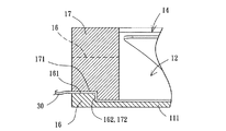
図10は本発明の実施例の放熱ファンによる位置決め部材を利用して電源接続線を押圧した状態の局部断面図である。図10を参照すると、導線口16の第一当接面161にはさらに第一階段部162が形成され、位置決め部材17の第二当接面171には好ましくは第一階段部162の形状に対応するように第二階段部172が形成され、さらに第一階段部162と第二階段部172とは互いに対応するように嵌合される。これにより、第一当接面161と第二当接面171が共同で電源接続線30を押圧して挟むように形成される時、電源接続線30は第一階段部162と第二階段部172によって図10に示されるような折り曲げの状態が形成される。それにより、比較的よい引っ張り防止の功能を提供することにより、外力によって不意に電源接続線30を引っ張ってしまうのを防止することができるため、電源接続線30の一端が電気的接続ポート22から緩んで脱落しないのを確保することができる。
FIG. 10 is a partial cross-sectional view showing a state where the power connection line is pressed using the positioning member by the heat radiating fan of the embodiment of the present invention. Referring to FIG. 10, a first stepped portion 162 is further formed on the
上述の如く、本発明の放熱ファン1、2、3、4によれば、確実に電気的接続ポート22を利用してフレーム10の導線口16に向かせることにより、そして電気的接続ポート22を基準線L上に位置させる結構の設計により、電源接続線30がフレーム10内部において巻き付けの方式を使用することなく、導線口16を貫穿して伸び入れて通過させることができるため、電源接続線30の組立上の便利性を有効に高めることができる。
As described above, according to the
本発明は、その精神及び必須の特徴事項から逸脱することなく他のやり方で実施することができる。従って、本明細書に記載した好ましい実施形態は例示的なものであり、限定的なものではない。 The present invention may be implemented in other ways without departing from the spirit and essential characteristics thereof. Accordingly, the preferred embodiments described herein are exemplary and not limiting.
1、2、3、4 放熱ファン
10 フレーム
11 側壁部
111 底板
112 係止爪
12 収容空間
13 軸座
14 風入口
15 風出口
16 導線口
161 第一当接面
162 第一階段部
17 位置決め部材
171 第二当接面
172 第二階段部
18 蓋板
20、20a、20b、20c 基板
21 コイル組
22 電気的接続ポート
23 凸部
24 布線板
25 駆動回路板
30 電源接続線
40 ファンホイール
41 ハブ
411 中心軸
412 永久磁石
70 放熱ファン
71 線整理構造
711 底部
712 側面支持部
713 止め板部
72 線材
80 放熱ファン
81 框体
811 収容室
812 溝道
82 ステータ座
821 電気的接続ポート
822 電源接続線
83 ファンホイール
831 永久磁石
84 蓋板
841 凸板
90 放熱ファン
91 ファン基座
911 導線溝
92 充填体
93 電線
94 ファンホイール
L 基準線
1, 2, 3, 4
Claims (12)
Priority Applications (1)
| Application Number | Priority Date | Filing Date | Title |
|---|---|---|---|
| JP2009134109A JP5249860B2 (en) | 2009-06-03 | 2009-06-03 | Heat dissipation fan |
Applications Claiming Priority (1)
| Application Number | Priority Date | Filing Date | Title |
|---|---|---|---|
| JP2009134109A JP5249860B2 (en) | 2009-06-03 | 2009-06-03 | Heat dissipation fan |
Publications (2)
| Publication Number | Publication Date |
|---|---|
| JP2010281241A JP2010281241A (en) | 2010-12-16 |
| JP5249860B2 true JP5249860B2 (en) | 2013-07-31 |
Family
ID=43538186
Family Applications (1)
| Application Number | Title | Priority Date | Filing Date |
|---|---|---|---|
| JP2009134109A Expired - Fee Related JP5249860B2 (en) | 2009-06-03 | 2009-06-03 | Heat dissipation fan |
Country Status (1)
| Country | Link |
|---|---|
| JP (1) | JP5249860B2 (en) |
Families Citing this family (4)
| Publication number | Priority date | Publication date | Assignee | Title |
|---|---|---|---|---|
| CN108425863A (en) * | 2017-02-14 | 2018-08-21 | 台达电子工业股份有限公司 | Heat radiation module |
| JP7327045B2 (en) * | 2019-09-26 | 2023-08-16 | ニデック株式会社 | Blower |
| CN115342074B (en) * | 2022-08-11 | 2024-03-15 | 深圳市永亿豪电子有限公司 | Combined fan structure |
| CN116044791A (en) * | 2023-02-03 | 2023-05-02 | 奇鋐科技股份有限公司 | Axial flow fan frame electrical connection structure |
Family Cites Families (10)
| Publication number | Priority date | Publication date | Assignee | Title |
|---|---|---|---|---|
| JPS5925000U (en) * | 1982-08-09 | 1984-02-16 | 株式会社東芝 | lateral flow fan |
| JPS6154860A (en) * | 1984-08-24 | 1986-03-19 | Nippon Denso Co Ltd | Commutatorless motor |
| JPH05248393A (en) * | 1992-03-06 | 1993-09-24 | Mitsubishi Electric Corp | Blower |
| KR19990003195A (en) * | 1997-06-25 | 1999-01-15 | 배순훈 | Pattern coil winding motor and its winding method |
| DE29718082U1 (en) * | 1997-10-11 | 1999-02-11 | Papst Motoren Gmbh & Co Kg | Small fan unit, especially for use as a circuit board fan |
| JP3055492U (en) * | 1998-07-01 | 1999-01-12 | 建準電機工業股▲分▼有限公司 | Improved structure of ultra-thin fan that can blow air in a certain direction |
| JP2000320496A (en) * | 1999-05-07 | 2000-11-21 | Shicoh Eng Co Ltd | Small fan |
| JP2003204176A (en) * | 2002-01-09 | 2003-07-18 | Nippon Densan Corp | Lead wire holding structure and fan motor provided with the same |
| JP2005127311A (en) * | 2003-10-02 | 2005-05-19 | Daikin Ind Ltd | Centrifugal blower and air conditioner using the same |
| JP2008138559A (en) * | 2006-11-30 | 2008-06-19 | Nidec Copal Corp | Blower-type fan motor |
-
2009
- 2009-06-03 JP JP2009134109A patent/JP5249860B2/en not_active Expired - Fee Related
Also Published As
| Publication number | Publication date |
|---|---|
| JP2010281241A (en) | 2010-12-16 |
Similar Documents
| Publication | Publication Date | Title |
|---|---|---|
| JP5102811B2 (en) | Inner rotor type heat dissipation fan | |
| TWI480468B (en) | Advection-type fan | |
| JP5444294B2 (en) | fan | |
| US8419385B2 (en) | Heat-dissipating fan | |
| JP5249860B2 (en) | Heat dissipation fan | |
| JP5427207B2 (en) | fan | |
| US8696332B2 (en) | Heat-dissipating fan | |
| US20110058963A1 (en) | Inner Rotor Type Motor and Heat Dissipating Fan Including the Inner Rotor Type Motor | |
| US8297950B2 (en) | Fan | |
| TW201317508A (en) | Lamp | |
| US8573817B2 (en) | Light device with enhanced flow rate and cooling efficiency and reduced noise and a cooling unit thereof | |
| CN103001363B (en) | Motor and stator coil group and cooling fan thereof | |
| US20060280632A1 (en) | Fan motor assembly | |
| JP2007082362A (en) | Rotating electric machine | |
| JP4809911B2 (en) | fan | |
| CN101713413B (en) | Inner rotor cooling fan | |
| US10566869B2 (en) | Three-phase brushless fan | |
| TWI516682B (en) | Impeller | |
| TWI461144B (en) | Heat-dissipating fan | |
| EP2295814B1 (en) | Heat-dissipating fan | |
| CN102025216B (en) | Motor and cooling fan with the motor | |
| TWI384127B (en) | Fan | |
| CN201159195Y (en) | self-illuminating cooling fan | |
| CN223594483U (en) | A blower | |
| CN101900125B (en) | cooling fan |
Legal Events
| Date | Code | Title | Description |
|---|---|---|---|
| A977 | Report on retrieval |
Free format text: JAPANESE INTERMEDIATE CODE: A971007 Effective date: 20111007 |
|
| A131 | Notification of reasons for refusal |
Free format text: JAPANESE INTERMEDIATE CODE: A131 Effective date: 20120105 |
|
| A521 | Request for written amendment filed |
Free format text: JAPANESE INTERMEDIATE CODE: A523 Effective date: 20120402 |
|
| A02 | Decision of refusal |
Free format text: JAPANESE INTERMEDIATE CODE: A02 Effective date: 20121002 |
|
| A521 | Request for written amendment filed |
Free format text: JAPANESE INTERMEDIATE CODE: A523 Effective date: 20130128 |
|
| A911 | Transfer to examiner for re-examination before appeal (zenchi) |
Free format text: JAPANESE INTERMEDIATE CODE: A911 Effective date: 20130204 |
|
| TRDD | Decision of grant or rejection written | ||
| A01 | Written decision to grant a patent or to grant a registration (utility model) |
Free format text: JAPANESE INTERMEDIATE CODE: A01 Effective date: 20130319 |
|
| A61 | First payment of annual fees (during grant procedure) |
Free format text: JAPANESE INTERMEDIATE CODE: A61 Effective date: 20130412 |
|
| R150 | Certificate of patent or registration of utility model |
Ref document number: 5249860 Country of ref document: JP Free format text: JAPANESE INTERMEDIATE CODE: R150 Free format text: JAPANESE INTERMEDIATE CODE: R150 |
|
| FPAY | Renewal fee payment (event date is renewal date of database) |
Free format text: PAYMENT UNTIL: 20160419 Year of fee payment: 3 |
|
| R250 | Receipt of annual fees |
Free format text: JAPANESE INTERMEDIATE CODE: R250 |
|
| R250 | Receipt of annual fees |
Free format text: JAPANESE INTERMEDIATE CODE: R250 |
|
| R250 | Receipt of annual fees |
Free format text: JAPANESE INTERMEDIATE CODE: R250 |
|
| S531 | Written request for registration of change of domicile |
Free format text: JAPANESE INTERMEDIATE CODE: R313531 |
|
| R350 | Written notification of registration of transfer |
Free format text: JAPANESE INTERMEDIATE CODE: R350 |
|
| R250 | Receipt of annual fees |
Free format text: JAPANESE INTERMEDIATE CODE: R250 |
|
| R250 | Receipt of annual fees |
Free format text: JAPANESE INTERMEDIATE CODE: R250 |
|
| R250 | Receipt of annual fees |
Free format text: JAPANESE INTERMEDIATE CODE: R250 |
|
| R250 | Receipt of annual fees |
Free format text: JAPANESE INTERMEDIATE CODE: R250 |
|
| R250 | Receipt of annual fees |
Free format text: JAPANESE INTERMEDIATE CODE: R250 |
|
| R250 | Receipt of annual fees |
Free format text: JAPANESE INTERMEDIATE CODE: R250 |
|
| LAPS | Cancellation because of no payment of annual fees |