JP5259276B2 - Transport vehicle with shutter - Google Patents
Transport vehicle with shutter Download PDFInfo
- Publication number
- JP5259276B2 JP5259276B2 JP2008172221A JP2008172221A JP5259276B2 JP 5259276 B2 JP5259276 B2 JP 5259276B2 JP 2008172221 A JP2008172221 A JP 2008172221A JP 2008172221 A JP2008172221 A JP 2008172221A JP 5259276 B2 JP5259276 B2 JP 5259276B2
- Authority
- JP
- Japan
- Prior art keywords
- shutter
- opening
- transport vehicle
- door pocket
- vehicle
- Prior art date
- Legal status (The legal status is an assumption and is not a legal conclusion. Google has not performed a legal analysis and makes no representation as to the accuracy of the status listed.)
- Expired - Fee Related
Links
Images
Landscapes
- Operating, Guiding And Securing Of Roll- Type Closing Members (AREA)
Description
本発明は、搬送物を出し入れするための開口部を開閉するシャッタを備えたシャッタ付き搬送車に関する。 The present invention relates to a transport vehicle with a shutter including a shutter that opens and closes an opening for taking in and out a transported object.
従来から、屋外仕様の搬送車として、搭載した荷物を風雨から保護して搬送するためのシャッタを備えた搬送車が知られている。また、屋内用として、荷物を出し入れする開口部に塵埃の侵入を防ぐためのシャッタを備えた装置が知られている(例えば、特許文献1参照)。シャッタ付き搬送車は、車体の開口部を開閉する電動式シャッタを備え、車体の天井付近にそのシャッタを収納する戸袋が取り付けられている。シャッタは、モータの回転によって戸袋から下方に繰り出されて開口部を閉じ、戸袋内に巻き上げられて開口部を開く。 2. Description of the Related Art Conventionally, as an outdoor specification transport vehicle, a transport vehicle including a shutter for transporting a loaded luggage while protecting it from wind and rain is known. In addition, an apparatus that includes a shutter for preventing intrusion of dust at an opening for taking in and out a luggage is known for indoor use (see, for example, Patent Document 1). A transport vehicle with a shutter includes an electric shutter that opens and closes an opening of a vehicle body, and a door pocket that houses the shutter is attached near the ceiling of the vehicle body. The shutter is drawn downward from the door pocket by the rotation of the motor to close the opening, and is rolled up in the door pocket to open the opening.
しかしながら、上述したシャッタ付き搬送車においては、シャッタの戸袋を車体の天井付近の高い位置に取り付けているので、搬送車の全高が高く、高重心となって安定性が良くない。
本発明は、上記問題を解決するものであり、搬送物を出し入れするための開口部を開閉するシャッタを備えたシャッタ付き搬送車において、搬送車の全高を低くすることを目的とする。 SUMMARY OF THE INVENTION The present invention solves the above-described problems, and an object of the present invention is to reduce the overall height of a transport vehicle in a transport vehicle with a shutter provided with a shutter that opens and closes an opening for taking in and out a transported product.
上記目的を達成するために請求項1に記載の発明は、車体の載置面上の空間を囲い搬送物を格納する格納部と、この格納部に搬送物を出し入れするための開口部を開閉するシャッタと、前記シャッタが開かれたときに該シャッタを収納する戸袋と、を備えたシャッタ付き搬送車において、前記戸袋は、前記開口部の床面側に設置され、前記シャッタの繰り出し先端側は索体を介してバランスウエイトが連結されており、前記索体は、前記格納部の天井側の内壁面の前記開口部の位置と、前記シャッタに直交する向きに離れた前記格納部の中央寄りの位置とに設置されている2以上のプーリを介して、前記バランスウェイトが前記中央寄りの位置において昇降可能となるように配置されているものである。
In order to achieve the above object, the invention according to
請求項2に記載の発明は、請求項1に記載のシャッタ付き搬送車において、前記シャッタの基端側は、前記戸袋内において該シャッタを繰り出し/繰り入れする電動軸に連結されているものである。 According to a second aspect of the present invention, in the transport vehicle with a shutter according to the first aspect, the base end side of the shutter is connected to an electric shaft that extends / retracts the shutter in the door pocket. .
請求項1に記載の発明によれば、戸袋が開口部の床面側にあるので、戸袋を車体の上部に設ける必要がなくなり、搬送車の全高を低くすることができると共に、搬送車が低重心となって安定性が向上する。また、戸袋が低い位置に設けられているにも拘らず、バランスウエイトにより、シャッタの開閉時の負荷は小さくなる。また、戸袋の位置が低いので、シャッタの保守作業が容易である。また、戸袋が従来のように天井側に設けられていると、雨天時に、戸袋にシャッタを繰り入れたとき、戸袋に雨水が溜まり、その排水のための構成を有していないと、溜まった雨水が格納部内に流下して問題であったが、そのようなことが解消される。 According to the first aspect of the present invention, since the door pocket is on the floor side of the opening, it is not necessary to provide the door pocket on the upper part of the vehicle body, the overall height of the transport vehicle can be reduced, and the transport vehicle can be lowered. It becomes the center of gravity and stability is improved. Moreover, although the door pocket is provided at a low position, the load at the time of opening and closing the shutter is reduced by the balance weight. Further, since the door pocket is low, the maintenance work of the shutter is easy. In addition, when the door pocket is provided on the ceiling side as in the past, when raining rains, when the shutter is moved into the door pocket, rainwater collects in the door pocket, and if there is no structure for drainage, the accumulated rainwater However, this problem is solved.
請求項2に記載の発明によれば、比較的重量のある電動軸の位置が低いので、搬送車が低重心となって安定性がさらに向上する。 According to the second aspect of the present invention, since the position of the relatively heavy electric shaft is low, the transport vehicle has a low center of gravity, and the stability is further improved.
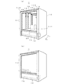
以下、本発明の一実施形態に係るシャッタ付き搬送車について説明する。図1(a)(b)は、本実施形態のシャッタ付き搬送車のシャッタを開いたときと、シャッタを閉じたときの外観を示す。シャッタ付き搬送車1(以下、搬送車という)は、車体10の載置面上111の空間を囲い搬送物30を格納する格納部11と、この格納部11に搬送物30を出し入れするための開口部112を開閉するシャッタ12と、シャッタ12が開かれたときにそのシャッタ12を収納する戸袋13と、を備える。戸袋13は、開口部112の床面FL側に設置されている。シャッタ12の繰り出し先端側には、格納部11の天井113側に設置されたプーリ14を介してバランスウエイト15が連結されている。
Hereinafter, a transport vehicle with a shutter according to an embodiment of the present invention will be described. FIGS. 1A and 1B show the external appearance when the shutter of the transport vehicle with a shutter according to the present embodiment is opened and when the shutter is closed. A
車体10の格納部11は、金属又は合成樹脂等から成り、搬送物30を内部に格納して風雨や塵埃等の車外環境から保護するものである。格納部11には、搬送物30を出し入れするための略矩形の開口部112が本実施形態では左右両側面に形成されている。開口部112は、前後側面に形成されていてもよい。シャッタ12は、開口部112を閉じて搬送物を風雨等から保護するものであり、例えば、合成樹脂シート又は防水処理された布等の防水性シート材から成る。シャッタ12は、複数の横長の金属等の板を簾状に上下に連結したものでもよいが、シート材のほうが、軽量であるために開閉動作が迅速となり、開閉時の発生音が小さく、また、簾状の連結部に塵埃が滞留するという欠点が無いので好ましい。
The
戸袋13は、シャッタ12を収納するものであり、シャッタ12を繰り出し、又は繰り入れる出入り口が開口しており、シャッタ12が戸袋13内に巻き取られて収納される。戸袋13が設置される開口部112の床面FL側、すなわち車体10の格納部11より下部は、内部スペースに余裕があり、そこに戸袋13を設置しても載置面111を高くする必要はない。
The
プーリ14は、格納部11の天井側の内壁面に設置される滑車である。プーリ14には、索体16が巻き掛けられる。索体16は、ベルト、又は、ロープ、チェーン等である。索体16の一端にシャッタ12の繰り出し先端側、反対端にシャッタ12に対するバランスウエイト15が接続され、シャッタ12とバランスウエイト15が昇降自在に連結される。バランスウエイト15は、シャッタ12と重量バランスを取るウエイトであり、カウンタウエイトとも呼ばれる。
The
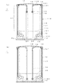
次に、搬送車1のシャッタ12の開閉構造について説明する。図2(a)(b)は、搬送車1のシャッタ12を開いたときと、シャッタ12を閉じたときの側面視状態を示す。シャッタ12は、電動開閉構成とされ、シャッタ12の基端側は、シャッタ12を繰り出し、又は繰り入れする電動軸131に連結されている。電動軸131は、戸袋13内に設けられる。シャッタ12の開閉は、手動とすることもできるが、搬送作業効率の観点から電動が好ましい。
Next, the opening / closing structure of the
電動軸131は、一端側にモータ18が接続され、モータ18によって回転駆動される。モータ18は、その回転子軸が電動軸131と同一方向となる配置にしてもよいし、車体10への艤装スペース等の都合により、例えば、傘歯車等を介して電動軸131と直交する配置にしてもよい。モータ18は、電動軸131内部に組み込んでもよい。電動軸131は、回転を制動停止するブレーキを有する。ブレーキは、モータ18の電磁力を制動力とする電磁ブレーキである。ブレーキは、機械的に制動する機械ブレーキでもよい。
The
シャッタ12の繰り出し先端側の上端部には、略全幅に亘って棒状部材121を備える。棒状部材121は、曲げ剛性が大きい、金属又は合成樹脂等の棒又はパイプ等である。棒状部材121の両端付近に索体16が接続される。その2本の索体16は、各々プーリ14から懸吊される。その対を成すプーリ14は、回転軸141で連結して、回転を直接に同期させてもよい。
A rod-shaped member 121 is provided at the upper end of the
格納部11の内壁面には、シャッタ12の昇降をガイドするシャッタ用ガイド部材17が設けられる。シャッタ用ガイド部材17は、例えば、スリットを有する上下に長い筒状であり、そのスリットに沿って棒状部材121が昇降する。シャッタ用ガイド部材17の形状は、これに限られるものではなく、例えば、半円筒形状又は平板形状とし、シャッタ用ガイド部材17と格納部11内壁面間を棒状部材121がガイドされるように構成してもよい。また、バランスウエイト15の昇降をガイドするウエイト用ガイド部材19が格納部11の内壁面に設けられる。ウエイト用ガイド部材19は、例えば、上下に長い筒状であり、その筒内をバランスウエイト15が昇降する。
A
搬送車1には、車輪22等から成る走行駆動のための装置が、車体10の下部、又は、車体10の前方又は後方に張り出して設けられる。また、搬送車1が屋外仕様の場合は、車体外側の開口部112の上部に雨樋21が設けられる。
In the
次に、シャッタ12の開閉について説明する。図2(a)に示すように、シャッタ12が開口部112を開いた状態では、シャッタ12は、戸袋13に収納されている。シャッタ12の棒状部材121は、戸袋13の出入口でストップされ、索体16は戸袋13内に入らない。このとき、バランスウエイト15は、最上昇位置にある。
Next, opening and closing of the
シャッタ12を閉じるときは、自動制御又は人によるスイッチ操作でモータ18を起動し、電動軸131を回転させてシャッタ12を戸袋13から繰り出す。バランスウエイト15は、ウエイト用ガイド部材19内を降下する。シャッタ12は、バランスウエイト15によって上に張られた状態で弛まずに上昇する。棒状部材121は、シャッタ用ガイド部材17に沿って上昇する。なお、シャッタ用ガイド部材17とウエイト用ガイド部材19は、索体16を囲って、搬送物30との接触を防いでいる。
When closing the
図2(b)に示すように、シャッタ12が開口部112を閉じると、モータ18を制動して電動軸131の回転を停止し、シャッタ12の上昇を停止する。シャッタ12が閉じた状態では、バランスウエイト15は、最降下位置にあって、棒状部材121を引っ張り、棒状部材121がシャッタ12を均一に引っ張る。従って、シャッタ12は、弛まずに開口部112を閉じる。また、軟質ゴムなどの弾力性を有する素材で形成した目張り部材を格納部11内壁面の開口部112周囲に設けて、シャッタ12と開口部112周囲との隙間をさらに確実に塞いでもよい。
As shown in FIG. 2B, when the
このように、戸袋13が開口部112の床面側にあるので、戸袋13を車体10の上部に設ける必要がなくなり、搬送車1の全高を低くすることができると共に、搬送車1が低重心となって安定性が向上する。また、戸袋13が低い位置に設けられているにも拘らず、バランスウエイト15により、シャッタ12の開閉時の負荷は小さくなる。また、戸袋13の位置が低いので、シャッタ12の保守作業が容易である。また、比較的重量のある電動軸131の位置が低いので、搬送車1が低重心となって安定性がさらに向上する。
Thus, since the
次に、搬送車1が無人搬送車である場合について説明する。搬送車1は、走行及びシャッタ12の開閉等を制御するプログラマブルコントローラ等から成る制御装置(図示せず)が、車体10の格納部11より下部に搭載される。搬送車1の制御装置による自動走行は、レール等の上を走行する軌道式であっても、レール等を用いずに誘導制御により走行する無軌道式であってもよい。誘導制御の場合は、設置した誘導体に沿って誘導するガイド式であっても、誘導体を設置せずに車載センサ等によって自車位置を計測して誘導するガイドレス式であってもよい。また、搬送車1には、ステーションとの間で無人で搬送物を移載するのための荷役移載装置(図示せず)が格納部11の載置面111に設けられる。ステーションとは、搬送物30の移載を行うために搬送車1が停止する場所のことである。
Next, the case where the
搬送車1は、格納部11に搬送物30を格納し、開口部112をシャッタ12で閉じ、搬送先のステーションまで自動走行する。ステーションに到着した搬送車1は、停止し、制御装置がモータ18を駆動し、シャッタ12を降下して戸袋13に収納する。開口部112が開かれると、制御装置がモータ18を制動してシャッタ12を停止し、荷役移載装置が搬送物30を格納部11内からステーションに移載する。移載完了は、例えば、制御装置が光電センサ等によって荷役移載装置上に搬送物30が無いこと検知して判断する。移載が完了すると、制御装置がモータ18を駆動し、シャッタ12を戸袋13から繰り出して上昇する。開口部112が閉じられると、制御装置がシャッタ12を停止し、搬送車1は、次のステーションに自動走行する。なお、搬送車1が、無人搬送車ではなく有人搬送車である場合は、搬送車1を人が運転してもよく、搬送物30の移載を人が行ってもよい。
The
次に、搬送車1が屋外仕様である場合の雨天時の搬送について説明する。搬送車1は、雨がかからない屋内等において搬送物30が格納部11に積み込まれ、目的のステーションまで走行する。屋外走行中は、搬送物30は格納部11とシャッタ12によって雨水の侵入から保護される。雨樋21が、車体10の屋根からシャッタ12に雨水が流れ落ちることを防いでいるが、降雨によってシャッタ12の外表面に雨水が直接に付着する。搬送車1が屋内のステーションに到着すると、開口部112が開かれて、搬送物30がステーションに移載される。開口部112が開かれる時、シャッタ12は降下して戸袋13に繰り入れられ、シャッタ12の外表面に付着した雨水は、戸袋13に溜まる。戸袋13に溜まった雨水は、戸袋13の底部に設けられたドレインを開いて排水される。
Next, the conveyance at the time of rain when the
戸袋が従来のように天井側に設けられていると、雨天時に、戸袋にシャッタを繰り入れたとき、戸袋に雨水が溜まり、その排水のための構成を有していないと、溜まった雨水が格納部内に流下して問題であったが、本実施形態では、戸袋13は、開口部112の床面FL側にあり、格納部11よりも下に位置するため、そのようなことが解消される。
If the door pocket is provided on the ceiling side as in the past, when raining rains, when the shutter is moved into the door pocket, rainwater accumulates in the door pocket. However, in this embodiment, the
なお、本発明は、上記の実施形態の構成に限られず、発明の要旨を変更しない範囲で種々の変形が可能である。例えば、搬送車1のシャッタ12の面数は、2面に限定されず、1面又は3面或いは4面であってもよい。
In addition, this invention is not restricted to the structure of said embodiment, A various deformation | transformation is possible in the range which does not change the summary of invention. For example, the number of surfaces of the
1 シャッタ付き搬送車
10 車体
11 格納部
111 載置面
112 開口部
113 天井
12 シャッタ
13 戸袋
131 電動軸
14 プーリ
15 バランスウエイト
DESCRIPTION OF
Claims (2)
前記戸袋は、前記開口部の床面側に設置され、
前記シャッタの繰り出し先端側は索体を介してバランスウエイトが連結されており、
前記索体は、前記格納部の天井側の内壁面の前記開口部の位置と、前記シャッタに直交する向きに離れた前記格納部の中央寄りの位置とに設置されている2以上のプーリを介して、前記バランスウェイトが前記中央寄りの位置において昇降可能となるように配置されていることを特徴とするシャッタ付き搬送車。 A storage section that encloses a space on the mounting surface of the vehicle body and stores a transported object, a shutter that opens and closes an opening for taking in and out the transported object, and stores the shutter when the shutter is opened. And a door carrier with a shutter,
The door pocket is installed on the floor side of the opening,
A balance weight is connected to the leading end side of the shutter via a cable body,
The rope includes two or more pulleys installed at a position of the opening of the inner wall surface on the ceiling side of the storage unit and a position near the center of the storage unit that is separated in a direction orthogonal to the shutter. And the balance weight is arranged so that it can be moved up and down at a position near the center .
Priority Applications (1)
| Application Number | Priority Date | Filing Date | Title |
|---|---|---|---|
| JP2008172221A JP5259276B2 (en) | 2008-07-01 | 2008-07-01 | Transport vehicle with shutter |
Applications Claiming Priority (1)
| Application Number | Priority Date | Filing Date | Title |
|---|---|---|---|
| JP2008172221A JP5259276B2 (en) | 2008-07-01 | 2008-07-01 | Transport vehicle with shutter |
Publications (2)
| Publication Number | Publication Date |
|---|---|
| JP2010012816A JP2010012816A (en) | 2010-01-21 |
| JP5259276B2 true JP5259276B2 (en) | 2013-08-07 |
Family
ID=41699366
Family Applications (1)
| Application Number | Title | Priority Date | Filing Date |
|---|---|---|---|
| JP2008172221A Expired - Fee Related JP5259276B2 (en) | 2008-07-01 | 2008-07-01 | Transport vehicle with shutter |
Country Status (1)
| Country | Link |
|---|---|
| JP (1) | JP5259276B2 (en) |
Family Cites Families (5)
| Publication number | Priority date | Publication date | Assignee | Title |
|---|---|---|---|---|
| US5271448A (en) * | 1992-07-27 | 1993-12-21 | Rytec Corporation | Movable barrier with two part guide follower |
| JPH10244838A (en) * | 1997-03-07 | 1998-09-14 | Yoshiharu Ueda | Method for opening/closing truck and its sheet member |
| JP2000130906A (en) * | 1998-10-28 | 2000-05-12 | Suzuki Motor Corp | Vehicle cold air leak prevention device |
| JP2002321801A (en) * | 2001-04-27 | 2002-11-08 | Matsushita Electric Ind Co Ltd | Automatic guided vehicle |
| JP2005277326A (en) * | 2004-03-26 | 2005-10-06 | Asyst Shinko Inc | Port for carrying in and out load, and storage apparatus |
-
2008
- 2008-07-01 JP JP2008172221A patent/JP5259276B2/en not_active Expired - Fee Related
Also Published As
| Publication number | Publication date |
|---|---|
| JP2010012816A (en) | 2010-01-21 |
Similar Documents
| Publication | Publication Date | Title |
|---|---|---|
| KR20140007723A (en) | Removable vehicle beekeeping equipment | |
| CN109057446B (en) | Rolling type car carrying plate storage device for three-dimensional parking lot and three-dimensional parking lot | |
| CN205346568U (en) | Automatic operating system of storage auxiliary material | |
| JP5259276B2 (en) | Transport vehicle with shutter | |
| JP2016013913A (en) | Building with elevator | |
| CN106164404B (en) | Sectional door with hoisting mechanism | |
| KR101027799B1 (en) | Electric Retractable Garage Door | |
| WO2016060309A1 (en) | Automatic cover apparatus for cargo compartment of truck | |
| CN108698798A (en) | Tensioning apparatus for elevator | |
| CN207418100U (en) | A kind of anti-tired elevator of the self-service escape of energy | |
| JP2010155664A (en) | Elevator door device | |
| JP7398815B2 (en) | dock shelter | |
| JP3236146U (en) | Dock shelter | |
| EP1053969A2 (en) | Elevator | |
| JP5364536B2 (en) | Mechanical parking equipment | |
| CN116946353A (en) | Flexible sliding door mounted at cargo compartment door of certain type conveyer | |
| ES2689440T3 (en) | Insulated loading dock | |
| JP4337113B2 (en) | Gard motor with built-in additional power | |
| KR102676980B1 (en) | Wind bar for speed door | |
| RU2109118C1 (en) | Automated garage-parking lot | |
| JPH0941699A (en) | Storage system | |
| CN219638743U (en) | Dust raising prevention system for lime product ash discharging area | |
| JP2591299Y2 (en) | Gondola for maintenance of elevator parking system | |
| JPH08128022A (en) | Geared wire load reducer for electric car stop | |
| JP4329100B2 (en) | Parking tower elevator |
Legal Events
| Date | Code | Title | Description |
|---|---|---|---|
| A621 | Written request for application examination |
Free format text: JAPANESE INTERMEDIATE CODE: A621 Effective date: 20101004 |
|
| A131 | Notification of reasons for refusal |
Free format text: JAPANESE INTERMEDIATE CODE: A131 Effective date: 20120313 |
|
| A977 | Report on retrieval |
Free format text: JAPANESE INTERMEDIATE CODE: A971007 Effective date: 20120315 |
|
| A521 | Request for written amendment filed |
Free format text: JAPANESE INTERMEDIATE CODE: A523 Effective date: 20120508 |
|
| A131 | Notification of reasons for refusal |
Free format text: JAPANESE INTERMEDIATE CODE: A131 Effective date: 20121106 |
|
| A521 | Request for written amendment filed |
Free format text: JAPANESE INTERMEDIATE CODE: A523 Effective date: 20130104 |
|
| TRDD | Decision of grant or rejection written | ||
| A01 | Written decision to grant a patent or to grant a registration (utility model) |
Free format text: JAPANESE INTERMEDIATE CODE: A01 Effective date: 20130402 |
|
| A61 | First payment of annual fees (during grant procedure) |
Free format text: JAPANESE INTERMEDIATE CODE: A61 Effective date: 20130424 |
|
| FPAY | Renewal fee payment (event date is renewal date of database) |
Free format text: PAYMENT UNTIL: 20160502 Year of fee payment: 3 |
|
| R150 | Certificate of patent or registration of utility model |
Ref document number: 5259276 Country of ref document: JP Free format text: JAPANESE INTERMEDIATE CODE: R150 Free format text: JAPANESE INTERMEDIATE CODE: R150 |
|
| R250 | Receipt of annual fees |
Free format text: JAPANESE INTERMEDIATE CODE: R250 |
|
| R250 | Receipt of annual fees |
Free format text: JAPANESE INTERMEDIATE CODE: R250 |
|
| S111 | Request for change of ownership or part of ownership |
Free format text: JAPANESE INTERMEDIATE CODE: R313111 |
|
| S531 | Written request for registration of change of domicile |
Free format text: JAPANESE INTERMEDIATE CODE: R313531 |
|
| S533 | Written request for registration of change of name |
Free format text: JAPANESE INTERMEDIATE CODE: R313533 |
|
| R350 | Written notification of registration of transfer |
Free format text: JAPANESE INTERMEDIATE CODE: R350 |
|
| LAPS | Cancellation because of no payment of annual fees |