JP5259377B2 - Superconducting magnet device - Google Patents
Superconducting magnet device Download PDFInfo
- Publication number
- JP5259377B2 JP5259377B2 JP2008325481A JP2008325481A JP5259377B2 JP 5259377 B2 JP5259377 B2 JP 5259377B2 JP 2008325481 A JP2008325481 A JP 2008325481A JP 2008325481 A JP2008325481 A JP 2008325481A JP 5259377 B2 JP5259377 B2 JP 5259377B2
- Authority
- JP
- Japan
- Prior art keywords
- superconducting magnet
- lead
- terminal
- wiring
- soundness
- Prior art date
- Legal status (The legal status is an assumption and is not a legal conclusion. Google has not performed a legal analysis and makes no representation as to the accuracy of the status listed.)
- Expired - Fee Related
Links
- 238000012790 confirmation Methods 0.000 claims description 55
- 230000005284 excitation Effects 0.000 claims description 18
- 230000005347 demagnetization Effects 0.000 description 7
- 238000000034 method Methods 0.000 description 7
- 238000010586 diagram Methods 0.000 description 4
- 230000007547 defect Effects 0.000 description 1
- 230000003203 everyday effect Effects 0.000 description 1
- 230000001681 protective effect Effects 0.000 description 1
- 230000009466 transformation Effects 0.000 description 1
Images
Landscapes
- Containers, Films, And Cooling For Superconductive Devices (AREA)
Description
本発明は、超電導磁気浮上式鉄道用車両に搭載される超電導磁石に係り、特に、各種端子を接続可能とするパワーリード着脱装置と組み合わせることにより、励磁下における強制消磁用電気回路の健全性確認機能を有する超電導磁石装置に関するものである。 The present invention relates to a superconducting magnet mounted on a superconducting magnetically levitated railway vehicle, and in particular, confirming the soundness of an electrical circuit for forced degaussing under excitation by combining with a power lead attaching / detaching device that can connect various terminals. The present invention relates to a superconducting magnet device having a function.
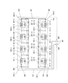
図2は従来の超電導磁石装置の構成を示す図である(下記特許文献1参照)。
この図において、101は台車の一方側に4個の超電導コイルが直列に接続された1位側超電導磁石、102は1位側超電導磁石101の一方の端子、103は1位側超電導磁石101のもう一方の端子、104−1,104−2は1位側超電導磁石101の主リード、105−1〜105−3は1位側超電導磁石101の補助リード、201は台車のもう一方側に4個の超電導コイルが直列に接続された2位側超電導磁石、202は2位側超電導磁石201の一方の端子、203は2位側超電導磁石201のもう一方の端子、204−1,204−2は2位側超電導磁石201の主リード、205−1〜205−3は2位側超電導磁石201の補助リード、301は2位側超電導磁石のもう一方の端子203と1位側超電導磁石のもう一方の端子103との間を接続する台車内渡り配線、302は2位側超電導磁石の一方の端子202に接続される第1パワーリード、303は1位側超電導磁石の一方の端子102に接続される第2パワーリード、304は第1パワーリード端子、305は第2パワーリード端子、401は第1,第2パワーリード端子304,305を接続可能なパワーリード(PL)着脱装置である。
FIG. 2 is a diagram showing a configuration of a conventional superconducting magnet device (see Patent Document 1 below).
In this figure, 101 is a first superconducting magnet in which four superconducting coils are connected in series on one side of the carriage, 102 is one terminal of the first
なお、1位側及び2位側超電導磁石101,201の各部には、各超電導コイル101−1〜101−4,201−1〜201−4と、永久電流スイッチ(PCS)101−5〜101−8,201−5〜201−8が接続され、これらの各超電導コイルと永久電流スイッチに並列に保護抵抗101−9〜101−12,201−9〜201−12が設けられている。
In each of the first and second
台車内パワーリード配線による超電導磁石の励消磁は、次の手順で行われている。
(1)パワーリード着脱装置401を第1及び第2パワーリード端子304,305に接続する。
(2)車両に搭載された1位側、2位側超電導磁石101,201と励磁電源装置(図示なし)で回路を構成する。
Excitation and demagnetization of the superconducting magnet by the power lead wiring in the carriage is performed in the following procedure.
(1) Connect the power lead attaching / detaching
(2) A circuit is constituted by the first and second
(3)遠方にある励磁電源装置からパワーリード着脱装置401を通して1位側、2位側超電導磁石101,201に電流を掃引する。
(4)パワーリード着脱装置401を第1及び第2パワーリード端子304,305から切り離す。
といった手順をとっている。
(3) The current is swept from the excitation power supply device located far away to the first and second
(4) The power lead attaching / detaching
The procedure is taken.
なお、これらの励消磁については、下記特許文献2などに詳細に説明されている。
従来、超電導磁石装置の強制消磁用電気回路の健全性確認は、図2に示すような構成の超電導磁石装置をパワーリード着脱装置401の仲介の下に励磁電源装置(図示なし)へ接続し、定格の1割程度の励磁を行った後に、超電導コイル毎に永久電流スイッチを開き、その際に発生する電圧を励磁電源装置の電圧計によって計測することにより、実施してきた。これは、超電導磁石が消磁された状態から開始する確認方法であり、超電導磁石の励磁下においても実施できるものではなかった。
Conventionally, the soundness confirmation of the electric circuit for forced demagnetization of the superconducting magnet device is performed by connecting a superconducting magnet device having a configuration as shown in FIG. After exciting about 10% of the rating, the permanent current switch is opened for each superconducting coil, and the voltage generated at that time is measured by the voltmeter of the excitation power supply device. This is a confirmation method starting from a state in which the superconducting magnet is demagnetized, and cannot be implemented even under excitation of the superconducting magnet.
上記したような従来の超電導磁石装置の強制消磁用電気回路の健全性確認方法は、超電導磁石が消磁された状態で実施する方法であるため、超電導磁石を毎朝出庫前に励磁して毎晩入庫後に消磁する運用であれば、健全性確認を実施する機会が毎日ある。しかし、今後、常時励磁して必要に応じて消磁する運用に進展すると、上記した方法では健全性確認を実施する機会が著しく減少してしまう。 The method for confirming the soundness of the electrical circuit for forced demagnetization of the conventional superconducting magnet device as described above is a method that is performed in a state where the superconducting magnet is demagnetized. If the operation is degaussing, there is an opportunity to check the soundness every day. However, in the future, when the operation progresses to an operation in which excitation is always performed and demagnetization is performed as necessary, the above-described method significantly reduces the chance of performing soundness confirmation.
本発明は、上記状況に鑑みて、超電導磁石の励磁下においても強制消磁用電気回路の健全性確認が実施できるようにした超電導磁石装置を提供することを目的とする。 In view of the above situation, an object of the present invention is to provide a superconducting magnet device capable of confirming the soundness of an electrical circuit for forced degaussing even under excitation of a superconducting magnet.
本発明は、上記目的を達成するために、
〔1〕超電導磁石装置において、超電導磁石に、パワーリードとその端子とは別個に、主リード健全性確認用配線(306)とその端子(309)、及び補助リード健全性確認用配線(307−1〜307−3,308−1〜308−3)とその端子(310−1〜310−3,311−1〜311−3)を設け、第1パワーリード端子(304)と第2パワーリード端子(305)に加えて前記主リード健全性確認用配線端子(309)及び補助リード健全性確認用配線端子(310−1〜310−3,311−1〜311−3)が並設された端子群を接続可能としたパワーリード着脱装置(401)と組み合わせることにより、励磁下における強制消磁用電気回路の健全性確認機能を有することを特徴とする。
In order to achieve the above object, the present invention provides
[1] In the superconducting magnet device, the main lead soundness confirmation wiring (306) and its terminal (309), and the auxiliary lead soundness confirmation wiring (307-) are connected to the superconducting magnet separately from the power lead and its terminal. 1 to 307-3, 308-1 to 308-3) and their terminals (310-1 to 310-3, 311-1 to 311-3), the first power lead terminal (304) and the second power lead. In addition to the terminal (305), the main lead soundness confirmation wiring terminal (309) and the auxiliary lead soundness confirmation wiring terminal (310-1 to 310-3, 311-1 to 311-3) are arranged in parallel. By combining with a power lead attachment / detachment device (401) capable of connecting a terminal group, it has a soundness confirmation function of an electrical circuit for forced degaussing under excitation.
〔2〕上記〔1〕記載の超電導磁石装置において、2位側超電導磁石(201)の主リード(204−2)の健全性確認用配線を兼ねる1位側超電導磁石(101)の主リード(104−2)の健全性確認用配線(306)と、前記2位側超電導磁石(201)の補助リード(205−1〜205−3)の健全性確認用配線(307−1〜307−3)と、前記1位側超電導磁石(101)の補助リード(105−1〜105−3)の健全性確認用配線(308−1〜308−3)と、前記2位側超電導磁石(201)の主リード(204−2)の健全性確認用配線端子を兼ねる前記1位側超電導磁石(101)の主リード(104−2)の健全性確認用配線端子(309)と、前記2位側超電導磁石(201)の補助リード(205−1〜205−3)の健全性確認用配線端子(310−1〜310−3)と、前記1位側超電導磁石(101)の補助リード(105−1〜105−3)の健全性確認用配線端子(311−1〜311−3)と、第1パワーリード端子(304)と第2パワーリード端子(305)の他に、前記2位側超電導磁石(201)の主リード(204−2)の健全性確認用配線端子を兼ねる前記1位側超電導磁石(101)の主リード(104−2)の健全性確認用配線端子(309)や、前記2位側超電導磁石(201)の補助リード(205−1〜205−3)の健全性確認用配線端子(310−1〜310−3)や、前記1位側超電導磁石(101)の補助リード(105−1〜105−3)の健全性確認用配線端子(311−1〜311−3)が接続可能なパワーリード着脱装置(401)とを備え、前記パワーリード着脱装置(401)は、前記第1パワーリード端子(304)と前記第2パワーリード端子(305)と前記主リード健全性確認用配線端子(309)と前記補助リード健全性確認用配線端子(310−1〜310−3,311−1〜311−3)が並設された端子群に接続されることを特徴とする。 [2] In the superconducting magnet device according to [1], the main lead of the first superconducting magnet (101) that also serves as the soundness confirmation wiring of the main lead (204-2) of the second superconducting magnet (201) ( 104-2) wiring for confirming soundness (306) and wiring for soundness confirmation of auxiliary leads (205-1 to 205-3) (307-1 to 307-3) of the second superconducting magnet (201). ), Sound check wirings (308-1 to 308-3) of the auxiliary leads (105-1 to 105-3) of the first superconducting magnet (101), and the second superconducting magnet (201). The main lead (104-2) of the main lead (104-2) and the second lead side of the main lead (104-2) of the first superconducting magnet (101), which also serves as the soundness check wiring terminal of the main lead (204-2) Auxiliary lead (205-1 to 205-1) of superconducting magnet (201) 205-3) wiring terminals for soundness confirmation (310-1 to 310-3) and wiring terminals for soundness confirmation of auxiliary leads (105-1 to 105-3) of the first superconducting magnet (101). (311-1 to 311-3), the first power lead terminal (304) and the second power lead terminal (305), as well as the main lead (204-2) of the second superconducting magnet (201). The wiring terminal (309) for soundness confirmation of the main lead (104-2) of the first superconducting magnet (101) that also serves as the wiring terminal for soundness confirmation, and the auxiliary lead of the second superconducting magnet (201) ( Soundness of wiring terminals (310-1 to 310-3) for soundness confirmation of 205-1 to 205-3) and auxiliary leads (105-1 to 105-3) of the first superconducting magnet (101) Confirmation wiring terminals (311-1 to 311-3) And a connection can power lead attachment apparatus (401), said power lead attachment apparatus (401), said main lead integrity confirmation to the first power lead terminal (304) a second power lead terminal (305) wherein the use wiring terminal (309) the auxiliary lead integrity confirmation wiring terminals (310-1~310-3,311-1~311-3) is characterized in that it is connected to a group of terminals arranged in parallel.
本発明によれば、超電導磁石の励磁下においても超電導磁石装置の強制消磁用電気回路の健全性確認が実施できるようになるので、超電導磁石を常時励磁して必要に応じて消磁する運用における健全性確認に適用することができる。 According to the present invention, since the soundness of the electric circuit for forced demagnetization of the superconducting magnet device can be confirmed even under the excitation of the superconducting magnet, the soundness in operation in which the superconducting magnet is always excited and demagnetized as necessary. It can be applied to sex confirmation.
本発明の超電導磁石装置は、超電導磁石に、パワーリードとその端子とは別個に、主リード健全性確認用配線(306)とその端子(309)、及び補助リード健全性確認用配線(307−1〜307−3,308−1〜308−3)とその端子(310−1〜310−3,311−1〜311−3)を設け、第1パワーリード端子(304)と第2パワーリード端子(305)に加えて前記主リード健全性確認用配線端子(309)及び補助リード健全性確認用配線端子(310−1〜310−3,311−1〜311−3)が並設された端子群を接続可能としたパワーリード着脱装置(401)と組み合わせることにより、励磁下における強制消磁用電気回路の健全性確認機能を有する。 In the superconducting magnet device of the present invention , the main lead soundness confirmation wiring (306) and its terminal (309) , and the auxiliary lead soundness confirmation wiring (307- ) are provided separately from the power lead and its terminal. 1 to 307-3, 308-1 to 308-3) and their terminals (310-1 to 310-3, 311-1 to 311-3) , the first power lead terminal (304) and the second power lead. In addition to the terminal (305) , the main lead soundness confirmation wiring terminal (309) and the auxiliary lead soundness confirmation wiring terminal (310-1 to 310-3, 311-1 to 311-3) are arranged in parallel. By combining with a power lead attachment / detachment device (401) that enables connection of a terminal group , it has a soundness confirmation function of an electrical circuit for forced degaussing under excitation.
以下、本発明の実施の形態について詳細に説明する。
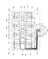
図1は本発明の実施例を示す超電導磁石装置の構成を示す図である。なお、上記した従来の構成と同様の部分については同じ符号を付してそれらの説明は省略する。
ここで、306は1位側超電導磁石101の主リード104−2の健全性確認用配線(2位側超電導磁石201の主リード204−2の健全性確認用配線を兼ねる)、307−1〜307−3は2位側超電導磁石201の補助リード205−1〜205−3の健全性確認用配線、308−1〜308−3は1位側超電導磁石101の補助リード105−1〜105−3の健全性確認用配線、309は1位側超電導磁石101の主リード104−2の健全性確認用配線端子(2位側超電導磁石201の主リード204−2の健全性確認用配線端子を兼ねる)、310−1〜310−3は2位側超電導磁石201の補助リード205−1〜205−3の健全性確認用配線端子、311−1〜311−3は1位側超電導磁石101の補助リード105−1〜105−3の健全性確認用配線端子、401は第1パワーリード端子304と第2パワーリード端子305の他に、1位側超電導磁石の主リードの健全性確認用配線端子(2位側超電導磁石の主リードの健全性確認用配線端子を兼ねる)309や、2位側超電導磁石の補助リードの健全性確認用配線端子310−1〜310−3や、1位側超電導磁石の補助リードの健全性確認用配線端子311−1〜311−3が接続可能なパワーリード着脱装置である。
Hereinafter, embodiments of the present invention will be described in detail.
FIG. 1 is a diagram showing a configuration of a superconducting magnet apparatus according to an embodiment of the present invention. In addition, the same code | symbol is attached | subjected about the part similar to the above-mentioned conventional structure, and those description is abbreviate | omitted.
Here, 306 is a wire for confirming the soundness of the main lead 104-2 of the first superconducting magnet 101 (also serves as a wire for confirming the soundness of the main lead 204-2 of the second superconducting magnet 201), 307-1. 307-3 is a wiring for confirming the soundness of the auxiliary leads 205-1 to 205-3 of the second
図1に示した超電導磁石装置は、従来の構成である図2の超電導磁石装置に対し、主リード健全性確認用配線306及びその端子309と、補助リード健全性確認用配線307−1〜307−3,308−1〜308−3及びその端子310−1〜310−3,311−1〜311−3を追加している。また、パワーリード着脱装置401は、第1パワーリード端子304と第2パワーリード端子305の他に、超電導磁石装置に追加した主リード健全性確認用配線端子309や補助リード健全性確認用配線端子310−1〜310−3,311−1〜311−3が接続可能となるように変更されている。
The superconducting magnet apparatus shown in FIG. 1 is different from the conventional superconducting magnet apparatus of FIG. 2 in that the main lead
超電導磁石101,201の主リード104−1,104−2,204−1,204−2と補助リード105−1〜105−3,205−1〜205−3は、溶接された真空断熱容器である超電導磁石101,201の内部にあり、超電導磁石を励磁して励磁電源装置(図示なし)から切離した後に、ある超電導コイルに不具合が発生した場合に、その永久電流スイッチやこれに対向する永久電流スイッチを開き、不具合が発生した超電導コイルやこれに対向する超電導コイルを強制消磁するために使用する。また、超電導磁石101,201の主リード104−1,104−2,204−1,204−2と補助リード105−1〜105−3,205−1〜205−3は、低温に冷やされた超電導コイル101−1〜101−4,201−1〜201−4への熱侵入を抑えるため、細長い棒形状となっている。したがって、超電導磁石装置の強制消磁用電気回路において、超電導磁石101,201の主リード104−1,104−2,204−1,204−2と補助リード105−1〜105−3,205−1〜205−3が、走行時の振動に伴う断線に対して注意を払い、その健全性を確認すべき部位である。
The main leads 104-1, 104-2, 204-1 and 204-2 of the
図1に示す超電導磁石装置では、第1パワーリード端子304、第2パワーリード端子305、及び追加した主リード健全性確認用配線端子309や補助リード健全性確認用配線端子310−1〜310−3,311−1〜311−3と、それらの端子が接続可能なパワーリード着脱装置を使用し、ある超電導コイルに対して励磁電源装置(図示なし)を接続し、永久電流スイッチは閉じたままに励磁電源装置から定格の1割程度の通電を行い、その際に発生する電圧が励磁電源装置の電圧計によって有意に零と計測されれば、その超電導コイルの強制消磁用電気回路の健全性が確認できたことになる。これは、超電導磁石の励磁下においても実施できる健全性確認方法である。また、定格の1割程度の通電なので、追加する主リード健全性確認用配線306や補助リード健全性確認用配線307−1〜307−3,308−1〜308−3の容量は、台車内渡り配線301や第1パワーリード302や第2パワーリード303の容量の1割程度でよく、著しい重量の増大にはならない。
In the superconducting magnet apparatus shown in FIG. 1, the first
なお、本発明は上記実施例に限定されるものではなく、本発明の趣旨に基づき種々の変形が可能であり、これらを本発明の範囲から排除するものではない。 In addition, this invention is not limited to the said Example, Based on the meaning of this invention, a various deformation | transformation is possible and these are not excluded from the scope of the present invention.
本発明の超電導磁石装置は、超電導磁石を常時励磁して必要に応じて消磁する運用においても強制消磁用電気回路の健全性を確認することができる超電導磁石装置として利用可能である。 The superconducting magnet device of the present invention can be used as a superconducting magnet device that can confirm the soundness of a forced degaussing electric circuit even in an operation in which a superconducting magnet is always excited and demagnetized as necessary.
101 1位側超電導磁石
101−1〜101−4,201−1〜201−4 超電導コイル
101−5〜101−8,201−5〜201−8 永久電流スイッチ(PCS)
101−9〜101−12,201−9〜201−12 保護抵抗
102,103 1位側超電導磁石の端子
104−1,104−2 1位側超電導磁石の主リード
105−1〜105−3 1位側超電導磁石の補助リード
201 2位側超電導磁石
202,203 2位側超電導磁石の端子
204−1,204−2 2位側超電導磁石の主リード
205−1〜205−3 2位側超電導磁石の補助リード
301 台車内渡り配線
302 第1パワーリード
303 第2パワーリード
304 第1パワーリード端子
305 第2パワーリード端子
306 主リード健全性確認用配線
307−1〜307−3,308−1〜308−3 補助リード健全性確認用配線
309 主リード健全性確認用配線端子
310−1〜310−3,311−1〜311−3 補助リード健全性確認用配線端子
401 パワーリード(PL)着脱装置
101 1st superconducting magnet 101-1 to 101-4, 201-1 to 201-4 Superconducting coil 101-5 to 101-8, 201-5 to 201-8 Permanent current switch (PCS)
101-9 to 101-12, 201-9 to 201-12 Protection resistance 102,103 Terminal of the first superconducting magnet 104-1, 104-2 Main lead of the first superconducting magnet 105-1 to 105-3 1 Auxiliary lead of position
Claims (2)
Priority Applications (1)
| Application Number | Priority Date | Filing Date | Title |
|---|---|---|---|
| JP2008325481A JP5259377B2 (en) | 2008-12-22 | 2008-12-22 | Superconducting magnet device |
Applications Claiming Priority (1)
| Application Number | Priority Date | Filing Date | Title |
|---|---|---|---|
| JP2008325481A JP5259377B2 (en) | 2008-12-22 | 2008-12-22 | Superconducting magnet device |
Publications (2)
| Publication Number | Publication Date |
|---|---|
| JP2010147395A JP2010147395A (en) | 2010-07-01 |
| JP5259377B2 true JP5259377B2 (en) | 2013-08-07 |
Family
ID=42567476
Family Applications (1)
| Application Number | Title | Priority Date | Filing Date |
|---|---|---|---|
| JP2008325481A Expired - Fee Related JP5259377B2 (en) | 2008-12-22 | 2008-12-22 | Superconducting magnet device |
Country Status (1)
| Country | Link |
|---|---|
| JP (1) | JP5259377B2 (en) |
Family Cites Families (6)
| Publication number | Priority date | Publication date | Assignee | Title |
|---|---|---|---|---|
| JPS5829388A (en) * | 1981-08-14 | 1983-02-21 | Japanese National Railways<Jnr> | Linear motor failure detection device |
| JPS61222209A (en) * | 1985-03-28 | 1986-10-02 | Mitsubishi Electric Corp | Superconducting magnet device and its external lead connection method |
| JPH0697643B2 (en) * | 1990-09-12 | 1994-11-30 | 株式会社日立製作所 | Superconducting magnet device |
| JP3419986B2 (en) * | 1996-03-27 | 2003-06-23 | 財団法人鉄道総合技術研究所 | Superconducting coil energizing wire protection method and device |
| JPH09290737A (en) * | 1996-04-25 | 1997-11-11 | Toyota Motor Corp | Anomaly detection device |
| JP4252156B2 (en) * | 1999-04-30 | 2009-04-08 | 財団法人鉄道総合技術研究所 | Ground-side excitation demagnetization circuit of superconducting magnet of magnetic levitation railway vehicle |
-
2008
- 2008-12-22 JP JP2008325481A patent/JP5259377B2/en not_active Expired - Fee Related
Also Published As
| Publication number | Publication date |
|---|---|
| JP2010147395A (en) | 2010-07-01 |
Similar Documents
| Publication | Publication Date | Title |
|---|---|---|
| Naidu et al. | Fault tolerant permanent magnet motor drive topologies for automotive x-by-wire systems | |
| CN101855695B (en) | Method and system for bypassing a power cell of a power supply | |
| Arumugam et al. | Turn–turn short circuit fault management in permanent magnet machines | |
| CN101689770B (en) | Transfer switch system with neutral current management | |
| US7948127B2 (en) | Connection method for rotating rectifiers on a generator | |
| CN104808142A (en) | Device and method for simulating short circuit faults of doubly-fed generator rotor | |
| SA515361138B1 (en) | Neutral point of a generator | |
| JP5259377B2 (en) | Superconducting magnet device | |
| EP3944478B1 (en) | Electric machine | |
| CN106099714A (en) | Three-half wiring mode current loop maintenance short circuit operation method | |
| JP4369417B2 (en) | Earth leakage breaker | |
| JP2000264048A (en) | Air conditioner | |
| JP4859163B2 (en) | Demagnetizing power lead connecting device for superconducting magnet of magnetic levitation railway vehicle | |
| JPH02237425A (en) | Dielectric breakdown detection circuit for instrument transformer and instrument transformer equipped with the detection circuit | |
| CN120188054A (en) | Power systems for identifying power failures | |
| JP6942673B2 (en) | Transformer | |
| Swanke et al. | Systematic Motor Drive Reliability Improvement Methodology Using Fault-Tolerant Modular Motor Drives | |
| WO2011065535A1 (en) | Current input transducer | |
| TW200410473A (en) | Serially-arranged linear motor | |
| TW201914145A (en) | Three-phase low-voltage AC load power supply protection circuit capable of achieving a safe operation by preventing the load rotor from being damaged by the imbalance of the relative phase voltage in the three phases | |
| CN201113715Y (en) | Double winding mutual backup brushless DC electric generator | |
| JP2015164146A (en) | inductor component | |
| JP2010011656A (en) | Terminal block | |
| Shirzad et al. | A Sustainable Approach to Magnet Thermal Class Selection Considering Irreversible Demagnetization | |
| CN117741352A (en) | Transformer insulation test method and device, computer equipment and storage medium |
Legal Events
| Date | Code | Title | Description |
|---|---|---|---|
| A621 | Written request for application examination |
Free format text: JAPANESE INTERMEDIATE CODE: A621 Effective date: 20110310 |
|
| A977 | Report on retrieval |
Free format text: JAPANESE INTERMEDIATE CODE: A971007 Effective date: 20120830 |
|
| A131 | Notification of reasons for refusal |
Free format text: JAPANESE INTERMEDIATE CODE: A131 Effective date: 20120925 |
|
| A521 | Written amendment |
Free format text: JAPANESE INTERMEDIATE CODE: A523 Effective date: 20121121 |
|
| TRDD | Decision of grant or rejection written | ||
| A01 | Written decision to grant a patent or to grant a registration (utility model) |
Free format text: JAPANESE INTERMEDIATE CODE: A01 Effective date: 20130423 |
|
| A61 | First payment of annual fees (during grant procedure) |
Free format text: JAPANESE INTERMEDIATE CODE: A61 Effective date: 20130424 |
|
| FPAY | Renewal fee payment (event date is renewal date of database) |
Free format text: PAYMENT UNTIL: 20160502 Year of fee payment: 3 |
|
| R150 | Certificate of patent or registration of utility model |
Ref document number: 5259377 Country of ref document: JP Free format text: JAPANESE INTERMEDIATE CODE: R150 Free format text: JAPANESE INTERMEDIATE CODE: R150 |
|
| LAPS | Cancellation because of no payment of annual fees |