JP5272000B2 - Method for manufacturing a sole having a slip fastener - Google Patents
Method for manufacturing a sole having a slip fastener Download PDFInfo
- Publication number
- JP5272000B2 JP5272000B2 JP2010504513A JP2010504513A JP5272000B2 JP 5272000 B2 JP5272000 B2 JP 5272000B2 JP 2010504513 A JP2010504513 A JP 2010504513A JP 2010504513 A JP2010504513 A JP 2010504513A JP 5272000 B2 JP5272000 B2 JP 5272000B2
- Authority
- JP
- Japan
- Prior art keywords
- manufacturing
- sole
- slip
- fastener
- injection
- Prior art date
- Legal status (The legal status is an assumption and is not a legal conclusion. Google has not performed a legal analysis and makes no representation as to the accuracy of the status listed.)
- Expired - Fee Related
Links
Images




Classifications
-
- A—HUMAN NECESSITIES
- A43—FOOTWEAR
- A43B—CHARACTERISTIC FEATURES OF FOOTWEAR; PARTS OF FOOTWEAR
- A43B13/00—Soles; Sole-and-heel integral units
- A43B13/14—Soles; Sole-and-heel integral units characterised by the constructive form
- A43B13/22—Soles made slip-preventing or wear-resisting, e.g. by impregnation or spreading a wear-resisting layer
-
- A—HUMAN NECESSITIES
- A43—FOOTWEAR
- A43B—CHARACTERISTIC FEATURES OF FOOTWEAR; PARTS OF FOOTWEAR
- A43B5/00—Footwear for sporting purposes
- A43B5/02—Football boots or shoes, i.e. for soccer, football or rugby
-
- A—HUMAN NECESSITIES
- A43—FOOTWEAR
- A43B—CHARACTERISTIC FEATURES OF FOOTWEAR; PARTS OF FOOTWEAR
- A43B13/00—Soles; Sole-and-heel integral units
- A43B13/14—Soles; Sole-and-heel integral units characterised by the constructive form
- A43B13/22—Soles made slip-preventing or wear-resisting, e.g. by impregnation or spreading a wear-resisting layer
- A43B13/223—Profiled soles
-
- A—HUMAN NECESSITIES
- A43—FOOTWEAR
- A43B—CHARACTERISTIC FEATURES OF FOOTWEAR; PARTS OF FOOTWEAR
- A43B5/00—Footwear for sporting purposes
- A43B5/001—Golf shoes
-
- A—HUMAN NECESSITIES
- A43—FOOTWEAR
- A43C—FASTENINGS OR ATTACHMENTS OF FOOTWEAR; LACES IN GENERAL
- A43C15/00—Non-skid devices or attachments
- A43C15/02—Non-skid devices or attachments attached to the sole
-
- A—HUMAN NECESSITIES
- A43—FOOTWEAR
- A43C—FASTENINGS OR ATTACHMENTS OF FOOTWEAR; LACES IN GENERAL
- A43C15/00—Non-skid devices or attachments
- A43C15/16—Studs or cleats for football or like boots
-
- A—HUMAN NECESSITIES
- A43—FOOTWEAR
- A43C—FASTENINGS OR ATTACHMENTS OF FOOTWEAR; LACES IN GENERAL
- A43C15/00—Non-skid devices or attachments
- A43C15/16—Studs or cleats for football or like boots
- A43C15/161—Studs or cleats for football or like boots characterised by the attachment to the sole
-
- A—HUMAN NECESSITIES
- A43—FOOTWEAR
- A43C—FASTENINGS OR ATTACHMENTS OF FOOTWEAR; LACES IN GENERAL
- A43C15/00—Non-skid devices or attachments
- A43C15/16—Studs or cleats for football or like boots
- A43C15/162—Studs or cleats for football or like boots characterised by the shape
-
- B—PERFORMING OPERATIONS; TRANSPORTING
- B29—WORKING OF PLASTICS; WORKING OF SUBSTANCES IN A PLASTIC STATE IN GENERAL
- B29D—PRODUCING PARTICULAR ARTICLES FROM PLASTICS OR FROM SUBSTANCES IN A PLASTIC STATE
- B29D35/00—Producing footwear
- B29D35/12—Producing parts thereof, e.g. soles, heels, uppers, by a moulding technique
- B29D35/122—Soles
-
- B—PERFORMING OPERATIONS; TRANSPORTING
- B29—WORKING OF PLASTICS; WORKING OF SUBSTANCES IN A PLASTIC STATE IN GENERAL
- B29D—PRODUCING PARTICULAR ARTICLES FROM PLASTICS OR FROM SUBSTANCES IN A PLASTIC STATE
- B29D35/00—Producing footwear
- B29D35/12—Producing parts thereof, e.g. soles, heels, uppers, by a moulding technique
- B29D35/128—Moulds or apparatus therefor
Landscapes
- Engineering & Computer Science (AREA)
- Mechanical Engineering (AREA)
- Health & Medical Sciences (AREA)
- General Health & Medical Sciences (AREA)
- Physical Education & Sports Medicine (AREA)
- Footwear And Its Accessory, Manufacturing Method And Apparatuses (AREA)
- Injection Moulding Of Plastics Or The Like (AREA)
Description
本発明は、少なくとも1つの滑り留め具を有するソールの製造方法に関し、滑り留め具がソールの底面に取り付けられている。 The present invention relates to a method of manufacturing a sole having at least one slip fastener, the slip fastener being attached to the bottom surface of the sole.
滑り留め具を有するソールは当業者に広く知られている。滑り留め具は、一般的な用途において用いられるような回転対称的なものだけでなく、靴底の底面に固定されるような非対称的な形態を有する場合もある。 Sole with slip fasteners are well known to those skilled in the art. The slip fastener is not only rotationally symmetric as used in general applications, but may also have an asymmetric form that is fixed to the bottom of the shoe sole.
国際特許出願公開第00/15068号は、靴底の底面に固定された滑り留め具を開示し、その滑り留め具は垂直方向の形状が実質的に三角形であり、その他にも仏国特許出願公開第2818876号は細長い形状の滑り留め具を開示する。 International Patent Application No. 00/15068 discloses a slip fastener fixed to the bottom of a shoe sole, the slip fastener being substantially triangular in vertical direction, and other French patent applications. Publication No. 2818876 discloses an elongated shaped slip fastener.
ここでは滑り留め具は、長手方向軸、すなわちソール表面に対して鉛直な垂直方向に延びている。 Here, the slip fasteners extend in a vertical direction perpendicular to the longitudinal axis, ie the sole surface.
独国特許出願公開第3032268号は、(ソールの側方領域において)傾斜して配置された滑り留め具、すなわち側方に向いた滑り留め具を開示している。同様の解決手段が独国特許出願公開第2828561号に記載されている。 German Patent Application No. 3032268 discloses slip fasteners which are arranged at an angle (in the lateral region of the sole), that is to say sideways. A similar solution is described in German Offenlegungsschrift 2828561.
いくつかの用途において、滑り留め具付き靴の基本的な効果を維持しつつ、地面に対して足が側方に滑らないように、特定の方向における抗力を発生させることが好ましい。典型的な具体例は、地面に対して特別なグリップ(把持力)を与える必要のあるゴルフ靴である。 In some applications, it is preferable to generate a drag in a specific direction so that the foot does not slip laterally with respect to the ground while maintaining the basic effect of a shoe with a slip fastener. A typical example is a golf shoe that needs to give a special grip (grip force) to the ground.
滑り留め具の非対称性がある程度を越えると、靴および滑り留め具付きソールの製造時において問題が生じる場合がある。ソールの多くは、射出モールド成形により製造されるため、滑り留め具は、予備成形部品として射出モールド金型内に挿入されて、インサート成形される。このため、滑り留め具が射出モールド金型の開閉方向に対してアンダーカット部分を有するとき、射出モールド成形されたソールを滑り留め具とともに離型することが困難となるという問題がある。 If the asymmetry of the slip fastener exceeds a certain level, problems may occur during the manufacture of the shoe and the sole with the slip fastener. Since most of the sole is manufactured by injection molding, the slip fastener is inserted into the injection mold as a preformed part and insert molded. For this reason, when the slide fastener has an undercut portion with respect to the opening and closing direction of the injection mold, there is a problem that it is difficult to release the injection molded sole together with the slide fastener.
実際、この問題は、複雑な金型技術(射出モールド金型内のダイ押圧デバイス)を用いることにより解決することができるが、必要な費用は極めて高額となる。 In fact, this problem can be solved by using complex mold technology (die pressing device in injection mold), but the cost is very high.
また、複数の滑り留め具をソール上で異なる方向に向くように配置したとき、すべての滑り留め具においてアンダーカット部分のない離型方向が存在せずこの方法はまったく機能しない。すなわち、滑り留め具付きソールが複数の滑り留め具を有し、これらがソール上で非対称的に配置されることが好ましい場合、上記問題はいっそう深刻である。 In addition, when a plurality of slip fasteners are arranged in different directions on the sole, there is no release direction without an undercut portion in all the slide fasteners, and this method does not work at all. That is, if the sole with slip fasteners has a plurality of slip fasteners, which are preferably arranged asymmetrically on the sole, the problem is even more serious.
したがって本発明の目的は、すべての方向に成形された滑り留め具を有する、すなわち滑り留め具の向きを任意に選択できる滑り留め具付きソールを簡便な手法で製造可能な上述のような方法を提供することである。適当ならば、著しい製造上の問題を生じることなく、各滑り留め具の配向方向を簡便な手法で変更することができるものである。さらに本発明に係る製造方法は、安価に実現可能であることにより特徴付けられるものである。特定の運動力学を考慮すべきである場合に、地面に対する把持力が改善されたことを特徴とする靴、特にゴルフ用靴を製造することができる。地面に対してゴルフプレーヤの足を最適に固定するために、このとき生じる力を必要な方向に選択的に伝達する必要がある。 Accordingly, an object of the present invention is to provide a method as described above, which has a slide fastener molded in all directions, that is, can manufacture a sole with a slide fastener in which the orientation of the slide fastener can be arbitrarily selected. Is to provide. If appropriate, the orientation of each slide fastener can be changed in a simple manner without causing significant manufacturing problems. Furthermore, the manufacturing method according to the present invention is characterized by being feasible at low cost. If specific kinematics are to be taken into account, it is possible to produce shoes, in particular golf shoes, characterized by improved grip on the ground. In order to optimally fix the golf player's foot to the ground, it is necessary to selectively transmit the force generated at this time in a necessary direction.
この目的を解決するための本発明に係る解決手段は、この製造方法は、a)少なくとも1つの滑り留め具を製造するステップと、滑り留め具は、ソールに連結できるクリート本体部を有し、クリート本体部には、使用時においては地面に向かって延びる少なくとも1つの延長部が設けられ、地面に面する延長部の端部の垂直突起領域が、少なくとも部分的に、好適には完全にクリート本体部の垂直突起領域の外側に配置され、b)滑り留め具を保持部品内に挿入するステップと、保持部品は、クリート本体部の少なくとも一部、および延長部と合同で、これらを収容する収容スペースを有し、c)射出モールド成形金型の間に形成されるキャビティ内に滑り留め具の一部が突出するように、保持部品とともに滑り留め具を少なくとも2パーツ射出モールド成形金型の凹部内に配置するステップと、d)射出モールド成形金型の間のキャビティ内にプラスティック溶融物を射出モールド成形して、滑り留め具の一部をプラスティック溶融物で形成することにより、ソールの少なくとも一部、好適にはソールの全体を、射出モールド成形するステップと、e)射出モールド成形されたソールならびに保持部品および滑り留め具を離型するステップと、f)保持部品から滑り留め具を取り外すステップとを有することを特徴とするものである。 In order to solve this object, the solution according to the present invention comprises the steps of: a) producing at least one slip fastener, the slip fastener having a cleat body that can be connected to the sole; In use, the cleat body is provided with at least one extension extending towards the ground, and the vertical projection area at the end of the extension facing the ground is at least partly, preferably completely cleated. Disposed outside the vertical projection region of the main body, b) inserting the slip fastener into the holding part, and the holding part is congruent with and accommodates at least a portion of the cleat main body and the extension. And c) at least two parts of the slip fastener together with the holding part so that a part of the slide fastener protrudes into the cavity formed between the injection molds. Placing in the recesses of the exit mold, and d) injection molding a plastic melt into the cavity between the injection molds to form part of the slip fastener with the plastic melt. A step of injection-molding at least a part of the sole, preferably the entire sole; e) releasing the injection-molded sole and the holding part and the slide fastener; and f) the holding part. And a step of removing the slip fastener from the step.
この製造方法により、より詳しく後述するが、射出モールド成形で製造する必要があるソールに、射出モールド成形金型を開く方向にアンダーカット部分を有する滑り留め具をより安価に形成することができる。ソールの材料で成形された滑り留め具を含むソールを問題なく離型することができる。 As will be described in more detail later by this manufacturing method, a slip fastener having an undercut portion in the direction of opening the injection mold can be formed on the sole that needs to be manufactured by injection molding at a lower cost. The sole including the slip fastener formed of the material of the sole can be released without any problem.
保持部品は、射出モールド成形金型の凹部の所定位置に挿入する際、射出モールド成形金型の開閉方向においてアンダーカット部分を有さないように設計されることが好ましい。特に、保持部品は、円筒形状を有し、保持部品は、その円筒形状の軸が射出モールド成形金型の開閉方向に配向されるように、射出モールド成形金型の凹部内に挿入される。 The holding part is preferably designed so as not to have an undercut portion in the opening / closing direction of the injection mold when inserted into a predetermined position of the recess of the injection mold. In particular, the holding component has a cylindrical shape, and the holding component is inserted into the recess of the injection mold so that the axis of the cylindrical shape is oriented in the opening and closing direction of the injection mold.
上記ステップd)においてソールを射出モールド成形するステップを行う前に、射出モールド成形金型のキャビティ内に薄膜状の強化部品を挿入してもよい。このとき、強化部品は、ガラスファイバまたはカーボンファイバである。 Before performing the step of injection molding the sole in step d), a thin-film reinforced component may be inserted into the cavity of the injection mold. At this time, the reinforcing component is a glass fiber or a carbon fiber.
とりわけ好適には、少なくとも2つの滑り留め具がソールに取り付けられ、2つの滑り留め具の少なくとも2つの延長部が異なる方向に向いている。 Particularly preferably, at least two slip fasteners are attached to the sole and at least two extensions of the two slip fasteners are oriented in different directions.
上記ステップd)においてソールを射出モールド成形するステップを行う際に、クリート本体部に取り付けられた複数の固定部品は、ソールの材料を用いて形成してもよい。 When performing the step of injection molding the sole in step d) above, the plurality of fixed parts attached to the cleat body may be formed using the sole material.
射出モールド成形後、保持部品を容易に離型するために、保持部品をポリアミド(商品名:ナイロン)により成形してもよい。 After injection molding, in order to release the holding part easily, the holding part may be formed from polyamide (trade name: nylon).
滑り留め具自体は、2部品構成のプラスティック部品であってもよい。滑り留め具は、少なくとも部分的にポリウレタン系熱可塑性エラストマ材料(TPU)から形成されるものであってもよい。 The slip fastener itself may be a two-part plastic part. The slip fastener may be at least partially formed from a polyurethane-based thermoplastic elastomer material (TPU).
換言すると、地面に向かって延びる少なくとも1つの延長部がクリート本体部に設けられ、延長部は、地面に面する端部を有するクリート本体部の垂直突起領域から離れて延びる。すなわち、この滑り留め具は、延長部がクリート本体部を越えて所定の方向に配置され、クリート本体部の垂直突起領域を離れるように延びることにより、地面に対する滑り留め具の特に横方向の良好な保持力を実現できるという点において特徴を有する。 In other words, at least one extension extending toward the ground is provided on the cleat body, and the extension extends away from the vertical projection region of the cleat body having an end facing the ground. In other words, the slip fastener is arranged in a predetermined direction beyond the cleat main body and extends away from the vertical protrusion area of the cleat main body, so that the slip fastener particularly in the lateral direction with respect to the ground is excellent. It has a feature in that a sufficient holding force can be realized.
好適には、延長部は長手方向軸に沿って細長い形状を有する。延長部の長手方向軸は、垂直方向との間に20°〜60°の角度αをなし、とりわけ30°〜50°の角度αをなす。 Preferably, the extension has an elongated shape along the longitudinal axis. The longitudinal axis of the extension forms an angle α of 20 ° to 60 ° with the vertical direction, in particular an angle α of 30 ° to 50 °.
延長部は、少なくとも長手方向軸に垂直な断面において、実質的に矩形形状を有するものであってもよい。 The extension may have a substantially rectangular shape at least in a cross section perpendicular to the longitudinal axis.
クリート本体部および少なくとも1つの延長部は、好適には、射出モールド成形部品として一体成形される。クリート本体部および少なくとも1つの延長部は、熱可塑性ポリウレタンエラストマ材料(TPU)から形成される。 The cleat body and the at least one extension are preferably integrally molded as an injection molded part. The cleat body and at least one extension are formed from a thermoplastic polyurethane elastomer material (TPU).
クリート本体部の形態は実質的に半球形状であってもよい。滑り留め具をソールにしっかりと固定するために、本発明の実施形態は、クリート本体部がソールに固定するための固定部品を有することを提案する。固定部品は、垂直方向に延びる円筒部材であり、ソールの構成材料を用いて形成されるものであってもよい。好適には、複数の円筒部材が、ソールに面した端面において、クリート本体部の周縁部の周りに配置される。好適には、固定部品はディスクに配置され、ディスクはクリート本体部に連結される。 The form of the cleat body may be substantially hemispherical. In order to securely fix the slip fastener to the sole, an embodiment of the present invention proposes that the cleat body has a fixing part for fixing to the sole. The fixed part is a cylindrical member extending in the vertical direction, and may be formed using a constituent material of the sole. Preferably, a plurality of cylindrical members are arranged around the periphery of the cleat body at the end face facing the sole. Preferably, the fixed part is disposed on the disk and the disk is connected to the cleat body.
靴のソールは、上述の種類の少なくとも1つの滑り留め具を有する。このとき好適には、少なくとも2つの滑り留め具がソールに取り付けられ、少なくとも2つの滑り留め具の延長部は少なくとも2つの異なる方向に向いている。 The sole of the shoe has at least one slip fastener of the type described above. Preferably, at least two slip fasteners are then attached to the sole, with the at least two slip fastener extensions facing at least two different directions.
本発明は、特にゴルフ用靴において有用である。 The present invention is particularly useful in golf shoes.
各図面において本発明の実施形態が図示されている。
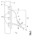
図1および図2に示す滑り留め具(クリート)1は、靴のソール3の底面2に固定されている。滑り留め具1は、実質的な半球形状を有するクリート本体部4を有する。クリート本体部4は、図1で明らかなように突起領域AGを有し、垂直方向Vから見ると、この実施形態では円形形状を有するものである。
In the drawings, embodiments of the invention are illustrated.
A slip fastener (cleat) 1 shown in FIGS. 1 and 2 is fixed to a
複数の固定部品12を用いて、滑り留め具1をソール3に安全に固定することができる。固定部品は、垂直方向Vに延びる実質的に円筒形状のピンとして構成され、以下詳述するように、靴およびソールの製造時における射出モールド成形により形成される。固定部品12を保持し、後にクリート本体部4に接続されるディスク19を用いて、滑り留め具1がソール3に確実に支持される。クリート本体部4、ディスク19、および固定部品12は、一体成形部品として形成される。
The sliding
重要なことに、少なくとも1つの延長部5がクリート本体部4から地面に向かって延びている。そのため、図1から最もよく分かるように、地面に面した端部を有する延長部5は、クリート本体部4の垂直突起領域AGから離れるように延びている。すなわち延長部5の地面に面した端部(この実施形態では矩形形状を有する)の垂直突起領域AFは、少なくともその一部、(この実施形態で図示するように)好適にはその全部がクリート本体部4の垂直突起領域AGの外側に配置される。
Importantly, at least one
延長部5は、長手方向軸Lを有し、これに沿って延びるようにロッド状に形成される。この長手方向軸Lは垂直方向との間に角度αをなし、この実施形態では約40度である。
The
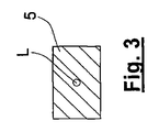
図3から明らかなように、延長部は実質的に矩形形状の断面を有する(図1のA−B線から見た断面図を参照されたい。)。 As is apparent from FIG. 3, the extension has a substantially rectangular cross-section (see the cross-sectional view taken along line AB in FIG. 1).
ここで提案されたデザインによれば、クリート本体部4による滑り留め具の既知の機能に加えて、延長部5により、滑り留め具1の地面に対する特定の側方保持機能を実現することができる。
According to the design proposed here, in addition to the known function of the slip fastener by the
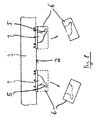
これに関連して、ゴルフ用靴の実現可能な実施形態を図4に示す。これはゴルフ用靴のソール3を底面から見たものであり、複数の滑り留め具1がソールに固定されている。
In this regard, a possible embodiment of a golf shoe is shown in FIG. In this case, the sole 3 of the golf shoe is viewed from the bottom, and a plurality of
滑り留め具1のそれぞれが図1に示す延長部5を有する。図4から明らかなように、地面に対する突起部は延長部5に沿って形成される。図示されているように、延長部5は異なる手法で配列され、すなわちさまざまな側面に向いている。したがって、地面上の延長部5の突起部と靴の長手方向軸Rとの間に角度βを規定することができる。図4の中央ソール領域において、3つの滑り留め具1が形成されている。
Each of the
図4に示す実施形態において、ソール内側面14からソール外側面15までのソール3の幅にわたって延びる仮想帯域13に沿って、一足の靴のうちの少なくとも一方に複数の滑り留め具1が配設されている。
In the embodiment shown in FIG. 4, a plurality of
外側ソール領域16にある延長部5は、靴の長手方向軸Rから外側面に向かって60°〜135°の角度βAをなす。また中央ソール領域17にある延長部5は、靴の長手方向軸Rから後方に向かって135°〜225°の角度βMをなす。さらに、内側ソール領域12にある延長部5は、靴の長手方向軸Rから内側面に向かって90°〜180°の角度βIをなす。
The
このとき仮想帯域13は、ソール外側面15からソール内側面14に延び、靴の長手方向軸Rからソール内側面8に向かって30°〜90°、好適には40°〜50°の角度γをなす。さらに仮想帯域13は、ソール外側面15から、ソール3の前端部および後端部の間のほぼ中央において形成される。図から分かるように、4〜6個の滑り留め具1が仮想帯域13に沿って並んで配置される。
At this time, the
上述のように滑り留め具1を調節することにより、ゴルフボールを打つときの運動力学に起因する力は、靴を通じて地面に伝達する必要があるが、最適な方法で伝達することができるという利点が得られる。こうして、特にゴルフをプレーする際、地面に対する靴の保持力を改善することができる。
By adjusting the
上述のように滑り留め具1を調節するとき、ヒットプロセスに従いゴルフクラブでボールを打つ際、力をゴルフクラブからプレーヤおよびその足を介して地面にさまざまな手法で伝達させなければならない点に留意する。この点において、特に仮想帯域13内に延長部5を有する滑り留め具1を配列したとき、最適な結果が得られる。
When adjusting the
上記実施形態の各実施例では、クリート本体部4には、ただ1つ(単一の)の延長部5を設けた。しかし2つまたは3つの延長部5を設けてもよく、滑り留め具1の一方の側面に対して星形形状に延びるようにしてもよい。
In each example of the above embodiment, the
一足の靴の2つのソールにおいて、複数の滑り留め具を鏡像のように(対称的に)配置する必要はない。2つの靴において、複数の滑り留め具を異なる手法で配置することも同様に合理的である。 In the two soles of a pair of shoes, it is not necessary to arrange the slip fasteners in a mirror image (symmetrically). It is equally reasonable to arrange the slip fasteners in two shoes in different ways.
製造に際して好適に作製するために、本発明は、さらに図5〜図8に例示的に図示する方法を提供する。 In order to be suitably fabricated during manufacture, the present invention further provides a method illustrated in FIGS.
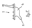
最初に、図5に示すように、滑り留め具1は、2部品構成の射出モールド成形部品として事前に作製される。上述のように、円筒状ピンの形態を有する固定部品12が滑り留め具に固定されている。
First, as shown in FIG. 5, the sliding
次の製造ステップにおいて、図6に示すように、滑り留め具1は保持部品6内に保持される。保持部品6は、滑り留め具1の表面と合同形状(合致する形状)に設計された収容スペース7を有する。すなわち滑り留め具1は、収容スペース7に正確に適合する。
In the next manufacturing step, as shown in FIG. 6, the sliding
次の製造ステップにおいて、図7に示すように、滑り留め具1および保持部品6は、2パーツ(2個で1組)の射出モールド成形金型9,10のうちの片方部分10に機械加工された凹部8内に挿入される。2つの部分金型9,10は、協働して既知の手法でキャビティ(空孔)11を形成し、そのキャビティ内に溶融物を充填して、ここではソールである所望する射出モールド成形部品を作製する。
In the next manufacturing step, as shown in FIG. 7, the sliding
図7に示すように、滑り留め具1の端部領域、すなわち固定部品12を含む領域は、金型9,10のキャビティ11内に突出し、キャビティ内に溶融物を射出モールド成形する際に形成される。
As shown in FIG. 7, the end region of the
このとき凹部8は円筒形状を有し、保持部品6の円筒形状に対応するものである。これは、射出モールド成形金型9,10を図7の双方向矢印に開閉する際に、保持部品6のアンダーカット部分のない離型を実現することができる。
At this time, the concave portion 8 has a cylindrical shape and corresponds to the cylindrical shape of the holding
射出モールド成形金型9,10の2つの片方部分が開いて、射出モールド成形部品が取り出され、図8に示す破線で示す保持部品6とともに構成部品が構成される。保持部品6がアンダーカット部分の有さないように設計されているので、保持部品6を問題なく離型することができる。保持部品6とともにソール3を離型した後、水平方向にピボット回転させることにより、保持部品6を取り外すことができ(図8の矢印を参照されたい。)、滑り留め具1を露出させる。
Two one parts of the injection molds 9 and 10 are opened, and an injection molded part is taken out, and a component part is configured together with a holding
こうして完成したソール3は、さらに使用できる状態となる。 The completed sole 3 is ready for further use.
提案された製造方法の利点によれば、射出モールド成形時に金型を離型する際、製造時の障害を回避して、アンダーカット部分を有する滑り留め具1をソールに問題なく固定することができる。保持金型6は、金型内にダイ押圧デバイスを設けることなく、簡便な製造方法を実現する可能性をもたらすものである。
According to the advantage of the proposed manufacturing method, when the mold is released during injection molding, it is possible to avoid the obstacle during the manufacturing and to fix the
さらに離型上の問題なく、効率的に、滑り留め具1のそれぞれを他の滑り留め具に対し相対的に位置合わせして配置することができる。特に、必要な場合には、滑り留め具のそれぞれに対する配置位置を容易に変更することができる。配置変更するために、コストの嵩む金型の変更を必要としない。別の保持部品を用いることにより、滑り留め具の形状を簡便な手法で変更することができる。
Furthermore, each of the
保持部品6は、好適には、容易に軟化するポリアミド(ナイロン)のような材料からなる。したがって保持部品6は、複数回使用することができる。
The holding
1:滑り留め具
2:底面
3:ソール
4:クリート本体部
5:延長部
6:保持部品
7:合同収容スペース
8:凹部
9:射出モールド成形金型部分
10:射出モールド成形金型部分
11:キャビティ
12:固定部品
13:仮想帯域
14:ソール内側面
15:ソール外側面
16:外側ソール領域
17:中央ソール領域
18:内側ソール領域
19:ディスク
AG:クリート本体部の垂直突起領域
AF:延長部の端部の垂直突起領域
L:延長部の長手方向軸
α:角度
V:垂直方向
R:靴の長手方向軸
βA:角度
βM:角度
βI:角度
γ:角度
1: Slip fastener 2: Bottom surface 3: Sole 4: Cleat body part 5: Extension part 6: Holding part 7: Joint housing space 8: Recess 9: Injection mold part 10: Injection mold part 11: Cavity 12: Fixed part 13: Virtual band 14: Sole inner side surface 15: Sole outer side surface 16: Outer sole region 17: Central sole region 18: Inner sole region 19: Disc A G : Vertical projection region A F of the cleat main body part: Vertical projection region L at the end of the extension portion: Longitudinal axis α of the extension portion: Angle V: Vertical direction R: Longitudinal axis of the shoe β A : Angle β M : Angle β I : Angle γ: Angle
Claims (10)
a)少なくとも1つの滑り留め具(1)を製造するステップと、
滑り留め具(1)は、ソール(3)に連結できるクリート本体部(4)を有し、
クリート本体部(4)には、使用時においては地面に向かって延びる少なくとも1つの延長部(5)が設けられ、
地面に面する延長部(5)の端部の垂直突起領域(AF)が、少なくとも部分的にクリート本体部(4)の垂直突起領域(AG)の外側に配置され、
b)滑り留め具(1)を単一部品からなる保持部品(6)内に挿入するステップと、
保持部品(6)は、クリート本体部(4)の少なくとも一部、および延長部(5)と合同で、これらを収容する収容スペース(7)を有し、
c)射出モールド成形金型(9,10)の間に形成されるキャビティ(11)内に滑り留め具(1)の一部が突出するように、保持部品(6)とともに滑り留め具(1)を少なくとも2パーツ射出モールド成形金型(9,10)の凹部(8)内に配置するステップと、
d)射出モールド成形金型(9,10)の間のキャビティ(11)内にプラスティック溶融物を射出モールド成形して、滑り留め具(1)の一部をプラスティック溶融物で形成することにより、ソール(3)の少なくとも一部、好適にはソールの全体を、射出モールド成形するステップと、
e)射出モールド成形されたソール(3)ならびに保持部品(6)および滑り留め具(1)を離型するステップと、
f)保持部品(6)から滑り留め具(1)を取り外すステップとを有することを特徴とする製造方法。 A method of manufacturing a sole (3) having at least one slip fastener (1), wherein the slip fastener (1) is attached to the bottom surface of the sole (3), the manufacturing method comprising:
a) producing at least one slip fastener (1);
The slip fastener (1) has a cleat body (4) that can be connected to the sole (3),
The cleat body (4) is provided with at least one extension (5) extending toward the ground when in use,
Extension facing the ground vertical projection area (A F) of the ends (5) is disposed at least partially outside the vertical projection area of the click Ried body portion (4) (A G),
b) inserting the slip fastener (1) into a holding part ( 6 ) comprising a single part ;
The holding part (6) has at least a part of the cleat body part (4) and an extension part (5) and has an accommodation space (7) for accommodating these,
c) The sliding fastener (1) together with the holding part (6) so that a part of the sliding fastener (1) protrudes into the cavity (11) formed between the injection molds (9, 10). ) At least in the recess (8) of the two-part injection mold (9, 10);
d) by injection molding a plastic melt into the cavities (11) between the injection molds (9, 10) and forming a part of the slip fastener (1) with the plastic melt, Injection molding at least a portion of the sole (3), preferably the entire sole;
e) releasing the injection-molded sole (3) and the holding part (6) and the slip fastener (1);
f) removing the slip fastener (1) from the holding part (6).
保持部品(6)は、射出モールド成形金型(9,10)の凹部(8)の所定位置に挿入する際、射出モールド成形金型(9,10)の開閉方向においてアンダーカット部分を有さないように設計されることを特徴とする製造方法。 The manufacturing method according to claim 1,
The holding component (6) has an undercut portion in the opening / closing direction of the injection mold (9, 10) when inserted into a predetermined position of the recess (8) of the injection mold (9, 10). A manufacturing method characterized by being designed so as not to exist.
保持部品(6)は、円筒形状を有し、
保持部品(6)は、その円筒形状の軸が射出モールド成形金型(9,10)の開閉方向に配向されるように、射出モールド成形金型(9,10)の凹部(8)内に挿入されることを特徴とする製造方法。 It is a manufacturing method of Claim 2, Comprising:
The holding part (6) has a cylindrical shape,
The holding part (6) is placed in the recess (8) of the injection mold (9, 10) so that its cylindrical shaft is oriented in the opening / closing direction of the injection mold (9, 10). A manufacturing method characterized by being inserted.
上記ステップd)においてソール(3)を射出モールド成形するステップを行う前に、射出モールド成形金型(9,10)のキャビティ(11)内に薄膜状の強化部品が挿入されることを特徴とする製造方法。 It is a manufacturing method of any one of Claims 1-3,
A thin-film reinforcing component is inserted into the cavity (11) of the injection mold (9, 10) before performing the step of injection molding the sole (3) in step d). Manufacturing method.
強化部品は、ガラスファイバまたはカーボンファイバであることを特徴とする製造方法。 The manufacturing method according to claim 4,
The manufacturing method, wherein the reinforcing component is a glass fiber or a carbon fiber.
少なくとも2つの滑り留め具(1)がソール(3)に取り付けられ、
2つの滑り留め具(1)の少なくとも2つの延長部(5)が異なる方向に向いていることを特徴とする製造方法。 It is a manufacturing method of any one of Claims 1-5,
At least two slip fasteners (1) are attached to the sole (3);
Manufacturing method, characterized in that at least two extensions (5) of the two slip fasteners (1) are oriented in different directions.
上記ステップd)においてソール(3)を射出モールド成形するステップを行う際に、クリート本体部(4)に取り付けられた複数の固定部品(12)は、ソール(3)の材料を用いて形成されることを特徴とする製造方法。 It is a manufacturing method of any one of Claims 1-6,
When performing the step of injection molding the sole (3) in step d), the plurality of fixed parts (12) attached to the cleat body (4) are formed using the material of the sole (3). The manufacturing method characterized by the above-mentioned.
保持部品(6)はポリアミドにより成形されることを特徴とする製造方法。 It is a manufacturing method of any one of Claims 1-7,
The manufacturing method characterized in that the holding part (6) is formed of polyamide.
滑り留め具(1)は、2部品構成のプラスティック部品であることを特徴とする製造方法。 It is a manufacturing method of any one of Claims 1-8,
The manufacturing method according to claim 1, wherein the slip fastener (1) is a plastic part having a two-part structure.
滑り留め具(1)は、少なくとも部分的にポリウレタン系熱可塑性エラストマ材料(TPU)から形成されることを特徴とする製造方法。 It is a manufacturing method of any one of Claims 1-9,
The manufacturing method, characterized in that the slip fastener (1) is at least partially formed from a polyurethane-based thermoplastic elastomer material (TPU).
Applications Claiming Priority (3)
| Application Number | Priority Date | Filing Date | Title |
|---|---|---|---|
| DE102007019270A DE102007019270B4 (en) | 2007-04-24 | 2007-04-24 | Method of making a stud sole |
| DE102007019270.5 | 2007-04-24 | ||
| PCT/EP2008/003111 WO2008128712A1 (en) | 2007-04-24 | 2008-04-17 | Method for producing a cleat sole |
Publications (2)
| Publication Number | Publication Date |
|---|---|
| JP2010524604A JP2010524604A (en) | 2010-07-22 |
| JP5272000B2 true JP5272000B2 (en) | 2013-08-21 |
Family
ID=39642661
Family Applications (1)
| Application Number | Title | Priority Date | Filing Date |
|---|---|---|---|
| JP2010504513A Expired - Fee Related JP5272000B2 (en) | 2007-04-24 | 2008-04-17 | Method for manufacturing a sole having a slip fastener |
Country Status (8)
| Country | Link |
|---|---|
| US (1) | US8206630B2 (en) |
| EP (1) | EP2142027B1 (en) |
| JP (1) | JP5272000B2 (en) |
| KR (1) | KR101474712B1 (en) |
| CN (1) | CN101674740B (en) |
| DE (1) | DE102007019270B4 (en) |
| ES (1) | ES2657678T3 (en) |
| WO (1) | WO2008128712A1 (en) |
Families Citing this family (40)
| Publication number | Priority date | Publication date | Assignee | Title |
|---|---|---|---|---|
| US8256145B2 (en) | 2008-09-26 | 2012-09-04 | Nike, Inc. | Articles with retractable traction elements |
| US8079160B2 (en) | 2008-09-26 | 2011-12-20 | Nike, Inc. | Articles with retractable traction elements |
| BRPI1014856A2 (en) | 2009-04-02 | 2016-05-03 | Nike International Ltd | "traction elements" |
| US8616892B2 (en) | 2009-04-02 | 2013-12-31 | Nike, Inc. | Training system for an article of footwear with a traction system |
| US8632342B2 (en) | 2009-05-28 | 2014-01-21 | Nike, Inc. | Training system for an article of footwear |
| US8573981B2 (en) | 2009-05-29 | 2013-11-05 | Nike, Inc. | Training system for an article of footwear with a ball control portion |
| JP5225960B2 (en) * | 2009-09-29 | 2013-07-03 | ダンロップスポーツ株式会社 | Golf shoes |
| US8453354B2 (en) * | 2009-10-01 | 2013-06-04 | Nike, Inc. | Rigid cantilevered stud |
| US8533979B2 (en) | 2010-02-18 | 2013-09-17 | Nike, Inc. | Self-adjusting studs |
| US8322051B2 (en) | 2010-02-23 | 2012-12-04 | Nike, Inc. | Self-adjusting studs |
| US9210967B2 (en) | 2010-08-13 | 2015-12-15 | Nike, Inc. | Sole structure with traction elements |
| US8529267B2 (en) | 2010-11-01 | 2013-09-10 | Nike, Inc. | Integrated training system for articles of footwear |
| US8713819B2 (en) | 2011-01-19 | 2014-05-06 | Nike, Inc. | Composite sole structure |
| US8763276B2 (en) | 2011-03-01 | 2014-07-01 | Nike, Inc. | Removable outsole elements for articles of footwear |
| US9504293B2 (en) | 2011-04-18 | 2016-11-29 | Nike, Inc. | Outsole with extendable traction elements |
| US8945449B2 (en) * | 2011-04-21 | 2015-02-03 | Nike, Inc. | Method for making a cleated plate |
| US9220320B2 (en) | 2011-09-16 | 2015-12-29 | Nike, Inc. | Sole arrangement with ground-engaging member support features |
| US8806779B2 (en) | 2011-09-16 | 2014-08-19 | Nike, Inc. | Shaped support features for footwear ground-engaging members |
| US8966787B2 (en) | 2011-09-16 | 2015-03-03 | Nike, Inc. | Orientations for footwear ground-engaging member support features |
| US9138027B2 (en) | 2011-09-16 | 2015-09-22 | Nike, Inc. | Spacing for footwear ground-engaging member support features |
| US9402442B2 (en) | 2012-04-27 | 2016-08-02 | Nike, Inc. | Sole structure and article of footwear including same |
| US9032645B2 (en) | 2012-07-30 | 2015-05-19 | Nike, Inc. | Support features for footwear ground engaging members |
| US20140215729A1 (en) * | 2013-02-05 | 2014-08-07 | Nike, Inc. | Cleats, cleated sole structures, molds, and molding methods for in-molding articles |
| NZ722100A (en) * | 2013-02-05 | 2017-03-31 | Nike Innovate Cv | Cleats, cleated sole structures, molds, and molding methods for in-molding articles |
| US9420851B2 (en) | 2013-12-31 | 2016-08-23 | Nike, Inc. | Footwear having lace receiving strands |
| US10123588B2 (en) | 2013-12-31 | 2018-11-13 | Nike, Inc. | Footwear ground engaging members having concave portions |
| US10016919B2 (en) * | 2014-07-03 | 2018-07-10 | Nike, Inc. | Method of making an article of footwear with a segmented plate |
| CN104983131B (en) * | 2015-08-06 | 2016-08-17 | 温州碧戈之都鞋业有限公司 | A kind of climbing boot |
| US9833958B2 (en) * | 2015-08-10 | 2017-12-05 | Teng-Jen Yang | Method for manufacturing a shoe sole with multi-material spikes |
| CN106466896A (en) * | 2015-08-14 | 2017-03-01 | 杨登任 | Method for manufacturing sole with multi-material golf shoe claw nails |
| DE102015115113B4 (en) | 2015-09-08 | 2018-03-01 | Teng-Jen Yang | Method of making a golf shoe sole with spikes of different materials |
| US20180310672A1 (en) | 2015-11-30 | 2018-11-01 | Treksta Inc. | Method for manufacturing spikes for sports shoes |
| CN107081923A (en) * | 2017-06-09 | 2017-08-22 | 东莞市鹏翼自动化科技有限公司 | An automatic injection molding method for manufacturing midsole shoes with non-slip printing on the bottom surface |
| KR102063360B1 (en) * | 2018-01-09 | 2020-01-07 | 황혜미 | Multi-purpose outsole with enhanced ground contact force |
| CN108851335B (en) * | 2018-06-20 | 2020-10-16 | 张建春 | Wet-skid-proof shoe outsole and manufacturing method thereof |
| JP6811495B1 (en) * | 2019-11-22 | 2021-01-13 | 数身 庄 | Outsole and footwear |
| WO2022153252A1 (en) * | 2021-01-15 | 2022-07-21 | Puma SE | Article of footwear having protruding members |
| US20250049173A1 (en) * | 2022-03-03 | 2025-02-13 | Acushnet Company | Golf shoe with reinforcement structure |
| US12364308B2 (en) * | 2022-03-03 | 2025-07-22 | Acushnet Company | Golf shoe with reinforcement structure |
| DE102024117553A1 (en) * | 2024-06-21 | 2025-12-24 | Adidas Ag | Method for manufacturing a footwear article and a mold for manufacturing a footwear article |
Family Cites Families (17)
| Publication number | Priority date | Publication date | Assignee | Title |
|---|---|---|---|---|
| US2658238A (en) * | 1949-01-05 | 1953-11-10 | James J Lazna | Method and apparatus for molding heel lifts |
| US3925529A (en) * | 1969-06-09 | 1975-12-09 | Wright & Co Inc E T | Method for making shoes with cleated bottoms |
| US3609889A (en) * | 1969-07-14 | 1971-10-05 | Bearfoot Corp | Spiked golf sole |
| DE2828561C3 (en) * | 1978-06-29 | 1981-11-05 | Puma-Sportschuhfabriken Rudolf Dassler Kg, 8522 Herzogenaurach | Outsole for sports shoes made of rubber or another material with rubber-elastic properties |
| FR2481088A1 (en) * | 1980-04-28 | 1981-10-30 | Patrick Sa | PROCESS AND MOLD FOR THE MANUFACTURE OF A SPORTED SHOE SPOKE SOLE |
| DE3032268A1 (en) * | 1980-08-27 | 1982-04-08 | Puma-Sportschuhfabriken Rudolf Dassler Kg, 8522 Herzogenaurach | OUTER SOLE FOR SPORTSHOES, MADE OF RUBBER OR OTHER MATERIAL WITH RUBBER-ELASTIC PROPERTIES |
| JPH01320001A (en) * | 1988-06-22 | 1989-12-26 | Asahi Corp | Manufacture of shoe sole with spike |
| TW228469B (en) * | 1991-06-19 | 1994-08-21 | Uhl Sportartikel Karl | |
| JPH08281660A (en) * | 1995-04-19 | 1996-10-29 | Nissan Motor Co Ltd | Positioning structure for insert parts in resin mold |
| US5887371A (en) * | 1997-02-18 | 1999-03-30 | Curley, Jr.; John J. | Footwear cleat |
| US6041526A (en) * | 1997-03-11 | 2000-03-28 | Trisport Limited | Ground-gripping elements for shoe soles |
| GB2341308B (en) | 1998-09-14 | 2001-03-28 | Mitre Sports Internat Ltd | Sports footwear and studs therefor |
| JP3134156B1 (en) * | 2000-02-01 | 2001-02-13 | 株式会社ジャパーナ | Spike tacks for golf shoes |
| FR2818876A1 (en) | 2000-12-29 | 2002-07-05 | Henri Charles Garbolino | Football boot has studs mounted eccentrically on plate with peripheral lip which fits into groove in its and fixed in place by bolt which fits through bore in plate into recess in sole |
| US6817117B1 (en) * | 2002-03-05 | 2004-11-16 | Nike, Inc. | Golf shoe outsole with oriented traction elements |
| EP1591031A1 (en) | 2004-04-26 | 2005-11-02 | Cheng-Hsian Chi | Method for making a shoe |
| US7313876B2 (en) | 2005-04-12 | 2008-01-01 | Wolverine World Wide, Inc. | Footwear outsole and method of manufacture |
-
2007
- 2007-04-24 DE DE102007019270A patent/DE102007019270B4/en not_active Expired - Fee Related
-
2008
- 2008-04-17 CN CN2008800133222A patent/CN101674740B/en not_active Expired - Fee Related
- 2008-04-17 EP EP08748974.6A patent/EP2142027B1/en not_active Not-in-force
- 2008-04-17 WO PCT/EP2008/003111 patent/WO2008128712A1/en not_active Ceased
- 2008-04-17 JP JP2010504513A patent/JP5272000B2/en not_active Expired - Fee Related
- 2008-04-17 KR KR1020097024343A patent/KR101474712B1/en not_active Expired - Fee Related
- 2008-04-17 ES ES08748974.6T patent/ES2657678T3/en active Active
- 2008-04-17 US US12/597,393 patent/US8206630B2/en not_active Expired - Fee Related
Also Published As
| Publication number | Publication date |
|---|---|
| EP2142027B1 (en) | 2017-11-08 |
| US20100139014A1 (en) | 2010-06-10 |
| JP2010524604A (en) | 2010-07-22 |
| DE102007019270B4 (en) | 2009-07-09 |
| CN101674740B (en) | 2011-12-28 |
| EP2142027A1 (en) | 2010-01-13 |
| KR20100017258A (en) | 2010-02-16 |
| US8206630B2 (en) | 2012-06-26 |
| WO2008128712A1 (en) | 2008-10-30 |
| ES2657678T3 (en) | 2018-03-06 |
| DE102007019270A1 (en) | 2008-11-06 |
| KR101474712B1 (en) | 2014-12-19 |
| CN101674740A (en) | 2010-03-17 |
Similar Documents
| Publication | Publication Date | Title |
|---|---|---|
| JP5272000B2 (en) | Method for manufacturing a sole having a slip fastener | |
| JP5309130B2 (en) | Shoe slip fastener, sole and shoe having the same | |
| JP7849441B2 (en) | Co-molded golf putter with integrated interlock mechanism | |
| US20250000213A1 (en) | Baseplate for a shoe | |
| JP6167240B2 (en) | Golf club head with polymer face | |
| JP6550137B2 (en) | Polymer golf club head with metal face | |
| JP4367748B2 (en) | Shoes with adjustable buffering means | |
| CN101500662B (en) | Golf clubs and club heads having fluid-filled bladders and/or inner chambers | |
| JP3199357B2 (en) | Sole core body of cycling shoe, method of molding the same, and mold device therefor | |
| US6748677B2 (en) | Detachable cleat system | |
| CN113301825A (en) | Skates or other shoes | |
| AU2008303045A1 (en) | An article of footwear | |
| TW201603741A (en) | Method of making an article of footwear with a segmented plate | |
| CN103260712A (en) | Co-molded, focused weighted, dimple arrayed hockey sticks and other composite structures | |
| US12290150B2 (en) | Stud for outsole, outsole for cleated shoe, method for producing outsole, and cleated shoe | |
| CN113841968B (en) | Sole component, molded assembly, and method of manufacturing for an article of footwear | |
| CN112469554A (en) | Skates or other shoes | |
| CN111741692B (en) | Sole for shoes | |
| CN114617333A (en) | Article of footwear | |
| US9833958B2 (en) | Method for manufacturing a shoe sole with multi-material spikes | |
| US20130104418A1 (en) | Soft toe post with reinforcement | |
| KR100771072B1 (en) | Golf shoes | |
| US9802093B2 (en) | Method for manufacturing a lacrosse head pocket | |
| JPS59137003A (en) | Method and mold for producing shoes with multi-color sole pattern | |
| JP3025450B2 (en) | Injection molding apparatus and injection molding method for shoe sole |
Legal Events
| Date | Code | Title | Description |
|---|---|---|---|
| A621 | Written request for application examination |
Free format text: JAPANESE INTERMEDIATE CODE: A621 Effective date: 20110223 |
|
| A977 | Report on retrieval |
Free format text: JAPANESE INTERMEDIATE CODE: A971007 Effective date: 20121219 |
|
| A131 | Notification of reasons for refusal |
Free format text: JAPANESE INTERMEDIATE CODE: A131 Effective date: 20121225 |
|
| A521 | Request for written amendment filed |
Free format text: JAPANESE INTERMEDIATE CODE: A523 Effective date: 20130325 |
|
| TRDD | Decision of grant or rejection written | ||
| A01 | Written decision to grant a patent or to grant a registration (utility model) |
Free format text: JAPANESE INTERMEDIATE CODE: A01 Effective date: 20130423 |
|
| A61 | First payment of annual fees (during grant procedure) |
Free format text: JAPANESE INTERMEDIATE CODE: A61 Effective date: 20130513 |
|
| R150 | Certificate of patent or registration of utility model |
Ref document number: 5272000 Country of ref document: JP Free format text: JAPANESE INTERMEDIATE CODE: R150 Free format text: JAPANESE INTERMEDIATE CODE: R150 |
|
| R250 | Receipt of annual fees |
Free format text: JAPANESE INTERMEDIATE CODE: R250 |
|
| R250 | Receipt of annual fees |
Free format text: JAPANESE INTERMEDIATE CODE: R250 |
|
| R250 | Receipt of annual fees |
Free format text: JAPANESE INTERMEDIATE CODE: R250 |
|
| LAPS | Cancellation because of no payment of annual fees |