JP5284591B2 - Game machine - Google Patents
Game machine Download PDFInfo
- Publication number
- JP5284591B2 JP5284591B2 JP2007031283A JP2007031283A JP5284591B2 JP 5284591 B2 JP5284591 B2 JP 5284591B2 JP 2007031283 A JP2007031283 A JP 2007031283A JP 2007031283 A JP2007031283 A JP 2007031283A JP 5284591 B2 JP5284591 B2 JP 5284591B2
- Authority
- JP
- Japan
- Prior art keywords
- power
- power supply
- gaming machine
- control unit
- supplied
- Prior art date
- Legal status (The legal status is an assumption and is not a legal conclusion. Google has not performed a legal analysis and makes no representation as to the accuracy of the status listed.)
- Expired - Fee Related
Links
- 238000001514 detection method Methods 0.000 claims description 35
- 230000001960 triggered effect Effects 0.000 claims description 2
- 230000002159 abnormal effect Effects 0.000 description 12
- 230000000694 effects Effects 0.000 description 11
- 230000005856 abnormality Effects 0.000 description 8
- 239000003990 capacitor Substances 0.000 description 5
- 238000012790 confirmation Methods 0.000 description 5
- 238000003780 insertion Methods 0.000 description 5
- 230000037431 insertion Effects 0.000 description 5
- 238000010586 diagram Methods 0.000 description 4
- 238000003745 diagnosis Methods 0.000 description 3
- 230000007274 generation of a signal involved in cell-cell signaling Effects 0.000 description 3
- 239000004973 liquid crystal related substance Substances 0.000 description 3
- 238000004519 manufacturing process Methods 0.000 description 3
- 238000000034 method Methods 0.000 description 3
- 238000012545 processing Methods 0.000 description 3
- 238000012986 modification Methods 0.000 description 2
- 230000004048 modification Effects 0.000 description 2
- 230000004044 response Effects 0.000 description 2
- 239000000758 substrate Substances 0.000 description 2
- HBBGRARXTFLTSG-UHFFFAOYSA-N Lithium ion Chemical compound [Li+] HBBGRARXTFLTSG-UHFFFAOYSA-N 0.000 description 1
- PWHULOQIROXLJO-UHFFFAOYSA-N Manganese Chemical compound [Mn] PWHULOQIROXLJO-UHFFFAOYSA-N 0.000 description 1
- 244000145845 chattering Species 0.000 description 1
- 230000006870 function Effects 0.000 description 1
- 229910001416 lithium ion Inorganic materials 0.000 description 1
- 229910052748 manganese Inorganic materials 0.000 description 1
- 239000011572 manganese Substances 0.000 description 1
- 229910052987 metal hydride Inorganic materials 0.000 description 1
- 229910052759 nickel Inorganic materials 0.000 description 1
- PXHVJJICTQNCMI-UHFFFAOYSA-N nickel Substances [Ni] PXHVJJICTQNCMI-UHFFFAOYSA-N 0.000 description 1
- -1 nickel metal hydride Chemical class 0.000 description 1
- 230000002093 peripheral effect Effects 0.000 description 1
- 238000007789 sealing Methods 0.000 description 1
- 239000004065 semiconductor Substances 0.000 description 1
- 230000003068 static effect Effects 0.000 description 1
Images


Landscapes
- Slot Machines And Peripheral Devices (AREA)
Description
本発明は、セキュリティを向上させた遊技機に関する。 The present invention relates to a gaming machine with improved security.
パチンコ機、スロットマシン等のように、遊技者が所定の遊技を行うことが可能な遊技機において、遊技機への外部電源投入時、各種電気部品の診断部位の異常有無を診断して、その診断結果を記憶手段に記憶するとともに、記憶した診断結果を表示装置に表示させるようにしたものがある(例えば、特許文献1参照)。 In a gaming machine such as a pachinko machine or a slot machine where a player can perform a predetermined game, when the external power supply to the gaming machine is turned on, it is diagnosed whether there is an abnormality in the diagnosis part of various electrical parts, There is one in which the diagnosis result is stored in a storage unit and the stored diagnosis result is displayed on a display device (for example, see Patent Document 1).
又、各種電気部品を収容した筐体とこの筐体の前面に開閉可能に設けられた前扉との間に、前扉の開閉を検出する開閉検出センサを設けたものもある(例えば、特許文献2参照)。
しかし、上記特許文献1、2に記載された遊技機においては、例えば、遊技機を生産する生産工場から遊技店に搬送する期間や遊技店の営業時間外等のように、遊技機に外部電源の電力が供給されていない電源遮断時、前扉が不正に開けられて、制御基板に不正行為が行われた事実があったとしても、これを監視する術はなくセキュリティ面で問題がある。
However, in the gaming machines described in
本発明は、上述のような従来の課題に鑑み、遊技機に外部電力が供給されていない電源遮断時における不正行為を監視できるようにして、セキュリティを向上させた遊技機を提供することを目的とする。 The present invention has been made in view of the above-described conventional problems, and an object thereof is to provide a gaming machine with improved security so that it is possible to monitor fraud at the time of power-off when external power is not supplied to the gaming machine. And
本発明によると、上記課題は、次のようにして解決される。
遊技機の筐体に開閉可能に設けられる前扉の開閉を検出可能な扉開閉検出センサと、前記遊技機に外部電力が供給されていないとき、前記筐体内に設けられる電子素子である記憶手段及び時計モジュールが動作するために必要な電力を供給可能なバックアップ電源と、前記遊技機に前記外部電力が供給されていないとき、前記扉開閉検出センサが前記前扉の開を検出したことを契機に、前記前扉を開いている時間に関係無く、後記記憶制御部が前記記憶手段に後記日時情報を記憶させるために必要な時間である所定時間を計時するタイマと、前記筐体内に設けられ、前記タイマが前記所定時間を計時している期間、前記バックアップ電源の電力を後記記憶制御部に供給し、前記所定時間の経過後、後記記憶制御部への前記バックアップ電源の電力供給を停止する電源供給制御部と、前記筐体内に設けられ、前記電源供給制御部により前記バックアップ電源の電力が供給されたことを契機に起動して、前記所定時間内に、前記扉開閉検出センサからの開信号を受けたときの日時情報を前記記憶手段に記憶させる記憶制御部とを備え、前記電源供給制御部は、前記遊技機に前記外部電力が供給されていないとき、電力を供給する必要がある前記記憶手段及び前記時計モジュールに前記バックアップ電源から電力を供給し、かつ前記外部電力が供給されることにより、前記記憶手段及び前記時計モジュールへの前記バックアップ電源からの電力の供給を停止して前記外部電力の供給に切り替え可能な電源切替部を含む。
According to the present invention, the above problem is solved as follows.
A door opening / closing detection sensor capable of detecting opening / closing of a front door provided to be openable / closable in a housing of the gaming machine, and a storage means which is an electronic element provided in the housing when external power is not supplied to the gaming machine And a backup power source capable of supplying power necessary for the operation of the clock module, and when the door open / close detection sensor detects the opening of the front door when the external power is not supplied to the gaming machine. In addition, a timer that counts a predetermined time, which is a time required for the postscript storage control unit to store postscript date and time information in the storage means , irrespective of the time during which the front door is opened, is provided in the housing. The power of the backup power source is supplied to the post-storage control unit while the timer is counting the predetermined time. After the predetermined time has elapsed, the backup power source is supplied to the post-storage control unit. And the power supply controller stops the power supply, the housing provided in the body, start triggered by the power of the backup power is supplied by the power supply control unit, within the predetermined time, the door opening and closing and a storage control unit that stores the date and time information when receiving the open signal from the detection sensor in the storage means, the power supply control unit, when the external power to the gaming machine is not supplied, the power the power is supplied from the backup power source to the storage means and the clock module is required to supply, and by the external power is supplied, the power supply from the backup power source to the storage means and the watch module And a power source switching unit capable of switching to supply of the external power.
本発明によれば、次のような効果が奏せられる。
請求項1記載の発明によると、遊技機に外部電力が供給されていないとき、バックアップ電源からの電力の供給により、記憶制御部が異常情報を記憶手段に記憶させるため、記憶手段に記憶された異常情報に基づいて不正行為を監視することができ、セキュリティの向上を図ることができる。又、異常状態検出センサが異常状態を検出した場合、電力供給制御部は、バックアップ電源からの電力を、記憶制御部が異常情報を記憶手段に記憶させるために必要な所定時間記憶制御部に供給して、所定時間経過後はバックアップ電源からの電力の供給を停止するため、バックアップ電源の消費電力を節約することができ、不正行為を長時間に亘って監視することができる。
さらに、遊技機に外部電力が供給されてないときは、電力を供給する必要がある電子素子にバックアップ電源から電力を供給し、又、外部電力が供給されたときは、電子素子に、バックアップ電源からの電力の供給を停止して外部電力を供給するため、バックアップ電源の電力消費を抑えることができる。
According to the present invention, the following effects can be obtained.
According to the first aspect of the present invention, when external power is not supplied to the gaming machine, the storage control unit stores the abnormality information in the storage unit by supplying power from the backup power source. It is possible to monitor fraud based on the abnormality information, and to improve security. When the abnormal state detection sensor detects an abnormal state, the power supply control unit supplies the power from the backup power source to the storage control unit for a predetermined time required for the storage control unit to store the abnormal information in the storage unit. Since the power supply from the backup power supply is stopped after a predetermined time has elapsed, the power consumption of the backup power supply can be saved, and illegal activities can be monitored over a long period of time.
Further, when external power is not supplied to the gaming machine, power is supplied from a backup power source to an electronic element that needs to be supplied, and when external power is supplied, backup power is supplied to the electronic element. Since the power supply from the power supply is stopped and the external power is supplied, the power consumption of the backup power supply can be suppressed.
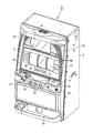
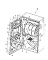
図1は、本発明の一実施形態を適用した遊技機(スロットマシン)の斜視図、図2は、前扉を開けた状態の遊技機の斜視図、図3〜図6は、制御回路の一例を示すブロック図又は回路図、図7は、タイムチャート図、図8は、表示装置に表示される表示例である。なお、以下の説明においては、図1、2における左斜め下方を「前方」とし、図1、2における右斜め上方を「後方」とする。 FIG. 1 is a perspective view of a gaming machine (slot machine) to which an embodiment of the present invention is applied, FIG. 2 is a perspective view of the gaming machine with a front door opened, and FIGS. FIG. 7 is a time chart, and FIG. 8 is a display example displayed on the display device. In the following description, the lower left diagonal in FIGS. 1 and 2 is referred to as “front”, and the upper right diagonal in FIGS.
遊技機1としてのスロットマシンは、前面が開放した正面視矩形の筐体2と、筐体2の左側部に上下方向を向く上下1対のヒンジ軸(図示略)により開閉可能に枢支された前扉3とを備える。
A slot machine as a gaming machine 1 is pivotally supported by a front-opening
図2に示すように、筐体2内には、遊技を統括的に制御する主制御基板4、遊技に係わる演出の制御及び前扉3の開閉情報を含む異常情報等を出力可能な副制御基板5、複数種類の図柄、数字等で構成される識別情報を変動表示及び停止表示可能な回転リールユニット6、遊技媒体であるメダルを貯留及び払出可能なホッパーユニット7、遊技機1の各種電気部品に外部電源の電力を供給する外部電源供給装置8等の遊技に係わる電気部品が収容されている。なお、各電気部品への外部電源供給装置8の外部電力供給は、主制御基板4を経由して行われる。
As shown in FIG. 2, in the
筐体2における前扉3に対向する箇所には、前扉3の開閉を検出可能な異常状態検出センサをなす扉開閉検出センサ60が配設されている。扉開閉検出センサ60が検出した開閉信号は、副制御基板5に送信される。なお、前扉3の開閉を検出する扉開閉検出センサ60は、機械的な作動で電気回路を開閉する機能をもつ機械式のリミットスイッチ等が好ましい。
A door opening /
主制御基板4は、不正な改造、交換等を防止するため、透明な基板ボックス内に収容された状態で筐体2内の後板2aに固定され、基板ボックスに設けられた封止部分を破壊しない限り基板ボックスから取り出せないようになっている。
The
回転リールユニット6は、外周面に識別情報が印刷又は貼付された左、中、右の3個の回転リール61と、各回転リール61を回転させるためのモータを制御するモータ駆動回路62とを備える。モータ駆動回路62は、主制御基板4が出力する制御コマンドに基いて、各回転リール61のモータの回転、停止を制御する。
The
前扉3の裏面側には、副制御基板5が出力する遊技に係わる情報、演出情報、前扉3の開閉情報及びその他の情報等を表示可能な液晶の表示画面91を有する表示装置9、副制御基板5が出力する制御信号を中継する中継基板10、効果音を発生する左右のスピーカ11、後述のメダル投入部18に投入されるメダルの真偽を判別し、真のメダルのみをホッパーユニット7に誘導するメダルセレクター12が設けられている。
On the back side of the
前扉3の裏面側周囲の開放側(右側)には、筐体2の適所に係脱可能な上、下のフック13が枢支されている。フック13は、筐体2の適所に係合することにより前扉3を閉鎖状態に拘束する。
On the open side (right side) around the back side of the
中継基板10には、扉開閉検出センサ60が検出した前扉3の開閉情報及びその他の情報を表示画面91に表示させるときに操作される異常確認用操作スイッチ14が設けられている。異常確認用操作スイッチ14は、遊技店の係員のみが所持しているキーを用いて、フック13の係合を解除して前扉3を開けた状態でのみ操作可能であって、遊技者は操作することはできない。
The
図1に示すように、前扉3の前面には、表示装置9の表示画面91に表示される遊技に係わる情報、演出情報、前扉3の開閉情報及びその他の情報等を透視可能な情報表示窓15、遊技機1に係わる遊技の履歴データを表示画面91に表示させるときに操作される遊技情報表示操作スイッチ16、各回転リール61の識別情報を3こまずつ透視可能な識別情報表示窓17、及び遊技を光演出するランプ27が設けられている。
As shown in FIG. 1, on the front surface of the
識別情報表示窓17の下方には、遊技を開始するときにメダルが投入されるメダル投入部18、メダルの賭数を最大限(3枚)に設定するMAXベットボタン19、メダルの賭数を1枚に設定する1ベットボタン20、全ての回転リール61を一斉に回転させるときに操作されるスタートレバー21、各回転リール61の回転を個別に停止させるときに操作される3個のストップボタン22、遊技を精算するときに操作される精算ボタン23、遊技店の係員が所持しているキーにより操作可能なキーシリンダ24等が設けられている。
Below the identification
キーシリンダ24をキーにより時計方向へ操作した場合には、フック13を解除作動させて前扉3を開くことができる。又、キーシリンダ24をキーにより反時計方向へ操作した場合には、前扉3の裏面側に設けられたリセットスイッチ25がキー操作を検出して遊技に係わる電気部品のエラーを解除させる。
When the
なお、MAXベットボタン19、1ベットボタン20、スタートレバー21、各ストップボタン22及び精算ボタン23には、それぞれの操作を検出するためのセンサが内蔵されている。
The MAX
次に、遊技機1の遊技方法について簡単に説明する。遊技者がメダルをメダル投入部18に投入して、MAXベットボタン19(又は、1ベットボタン20)の操作により遊技の賭数を設定した後、スタートレバー21を操作して各回転リール61を一斉に回転させる。そして、所定時間経過後に各回転リール61に対応する各ストップボタン22を順次操作して、各回転リール61を停止させる。
Next, a gaming method of the gaming machine 1 will be briefly described. After the player inserts a medal into the
各回転リール61が停止したときの、識別情報表示窓17内の有効ライン上に表示される左、中、右の識別情報の組み合わせにより、入賞の有無、及び賞の大小が決定され、入賞態様に応じた数のメダルがホッパーユニット7から前扉3の下部に設けられた受皿3aに払い出される。そして、入賞のうち特定遊技状態となった場合には、所定の効果音をスピーカ11から発生させたり、表示装置9の表示画面91に特定遊技状態に係わる遊技情報や演出情報等を表示させる等して演出効果を高める。
The combination of left, middle and right identification information displayed on the active line in the identification
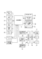
次に、図3を参照して、遊技機1全体の制御回路について説明する。
主制御基板4は、制御プログラム及びデータを記憶したROMとCPUのワークエリアとして機能するRAMとともに一体型のワンチップCPUとして構成される制御部を有し、ROMに記憶された制御プログラムにより、一連の制御処理を実行する。
Next, a control circuit of the entire gaming machine 1 will be described with reference to FIG.
The
主制御基板4におけるROMには、遊技機1の遊技に関する基本的なプログラムが記憶されているとともに、各入賞の当選確率、入賞に対するメダルの払出し数等のデータテーブルが書き込まれている。CPUは、ROMのプログラムにしたがって遊技制御、例えば、回転ユニット6における回転リール61の回転、停止の制御等を実行する。
The ROM on the
主制御基板4の入力インターフェースには、外部電源供給装置8、MAXベットボタン19、1ベットボタン20、スタートレバー21、ストップボタン22、精算ボタン23、リセットスイッチ25、メダルセレクター12を通過したメダルを検出するメダル検出センサ26等が接続されている。
In the input interface of the
主制御基板4の出力インターフェースには、ホッパーユニット7、回転リールユニット6のモータ駆動回路62及び副制御基板5が接続されている。
The output interface of the
主制御基板4の制御部は、スタートレバー21のスタート信号を受けたことを契機に、数値データ更新データにより入賞か否かを抽選し、その抽選結果に基づく制御コマンドを回転リールユニット6のモータ駆動回路62に送信して、各回転リール61のモータを個別に制御するとともに、副制御基板5に演出コマンドを送信する。
When the control unit of the
副制御基板5の入力インターフェースには、主制御基板4、異常確認用操作スイッチ14、遊技情報表示操作スイッチ16及び扉開閉検出センサ60が接続され、又、同じく出力インターフェースには、中継基板10を経由して、表示装置9、スピーカ11、ランプ27が接続されている。
The
外部電源供給装置8に外部電源が接続されて、遊技機1に外部電力が供給されているとき(例えば、遊技店の営業中)、副制御基板5は、主制御基板4が出力する制御コマンドに基づいて、表示装置9の液晶制御基板92に表示情報を送信して表示画面91に文字、画像等を表示させたり、ランプ27を点灯表示させたり、スピーカ11から音声、音楽等を出力させたりして演出表示を行う。
When an external power supply is connected to the external
副制御基板5は、後述のように、扉開閉検出センサ60からの開閉信号を受けたときの開閉情報、及び遊技機1に外部電力が投入されたときの日時情報を記憶する。なお、開閉情報としては、扉開閉検出スイッチ60が前扉3の開閉を検出したときの日時情報、及びそのときの電力源を識別する後述の電力供給源識別情報を含む。
As will be described later, the
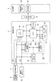
図4に示すように、副制御基板5には、制御プログラム及び各種データを記憶したROM51と、主制御基板4から出力される制御コマンド、外部電源供給装置8が外部電源に接続されたときの外部電源投入信号101及び扉開閉検出センサ60から出力される開閉信号102等をI/Oポート54を介して読み込む記憶制御部をなすCPU52と、CPU52により各種情報が記憶される記憶手段をなすRAM53と、外部電力(例えば、定格電圧DC3.3V)の供給が停止されているとき(外部電源供給装置8が外部電源に接続されていないか、又は外部電源供給装置8がOFFしているとき)、CPU52が動作するために必要なバックアップ電力(例えば、定格電圧DC3V)を供給可能な充電式のバックアップ電源55と、外部電力又はバックアップ電力により常時駆動可能な時計モジュール56と、ROM51、CPU52、RAM53及び時計モジュール56に供給する電力を制御する電源供給制御部50等が実装されている。なお、本実施形態においては、RAM53及び時計モジュール56が、本発明における常時、電力を供給する必要がある電子素子をなす。
As shown in FIG. 4, the
本実施形態おける記憶手段は、バックアップ電源55の消費電力を押さえるために、動作時のみ電力を必要するSRAM(static random access memory)やフラッシュメモリ(flash memory)等の不揮発性の半導体メモリを用いるが、これに代えて、電源遮断時にもバックアップ電源55により記憶を保持可能なDRAM(dynamic random access memory ディーラム(随時書き込み・読み出し可能メモリ))を用いても良い。
The storage means in this embodiment uses a non-volatile semiconductor memory such as SRAM (static random access memory) or flash memory that requires power only during operation in order to reduce the power consumption of the
また、バックアップ電源55としては、ニッケル水素電池、リチウムイオン電池等、放電後も充電することによって元の状態に戻して繰り返し使用可能な二次電池を使用するのが望ましい。勿論、マンガン電池やアルカリ電池等の一次電池を使用することも可能である。
As the
CPU52は、遊技機1に外部電力が供給されていないとき、例えば、遊技機1を生産工場から遊技店に搬送する期間や遊技店の営業時間外の期間、扉開閉検出センサ60から開閉信号102が出力されると、電源供給制御部50の後述のCPU電源供給制御部500から出力されるバックアップ電力によって、それまで停止していたものが起動して、開閉信号102を受けたときの日時情報及びそのときの電力供給源がバックアップ電力である旨の電力供給情報をRAM53に記憶させる。また、遊技機1が遊技店に据え付けられる等して、外部電源供給装置8が外部電源に接続されて、遊技機1に外部電力が投入されることにより、CPU52は、主制御基板4から送信される外部電源投入信号101に基づいて外部電源が投入されたときの日時情報をRAM53に記憶させる。さらに、遊技機1に外部電力が供給されている期間、例えば、遊技店の営業時間内、CPU52は、CPU電源供給制御部500から出力される外部電力により駆動しており、扉開閉検出センサ60からの開閉信号102を受けると、そのときの開閉信号を受けたときの日時情報及びそのときの電力供給源が外部電力であることを識別する電力供給情報をRAM53に記憶させる。
When the external power is not supplied to the gaming machine 1, the CPU 52 opens and closes the opening /
RAM53に記憶された情報の開閉信号102を受けたときの日時情報、電力供給源を識別する電力供給情報及び外部電源が投入されたときの日時情報は、開、閉日時情報201、202、電力供給源識別情報204及び外部電源投入日時情報203として、図8に示すように、表示装置9の表示画面91に表示させることができる。
The date and time information when receiving the open /
電源供給制御部50は、ROM51、CPU52に供給する電力を制御するCPU電源供給制御部500と、RAM53及び時計モジュール56に供給する電力を制御するRAM電源供給制御部550を含んでいる。
The power
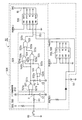
図5に示すように、CPU電源供給制御部500は、扉開閉検出センサ60から出力される開閉信号102を信号処理する信号処理部510と、開閉信号102に基づいてバックアップ電力を出力させるためのバックアップ電源供給制御信号103を生成するバックアップ電源投入制御信号生成部520と、ROM51及びCPU52に供給する電力源65を外部電力又はバックアップ電力に切替可能なCPU電源切替部530とを有している。
As shown in FIG. 5, the CPU power
RAM電源供給制御部550は、RAM53及び時計モジュール56に供給する電力源を外部電力又はバックアップ電力に切替可能なRAM電源切替部560を含んでいる。
The RAM power
図6に示すように、CPU電源供給制御部500の信号処理部510は、扉開閉検出センサ60に直列に接続される抵抗R1とコンデンサC1からなるCR回路により形成され、扉開閉検出センサ60から出力される開閉信号のチャタリングを防止する。
As shown in FIG. 6, the
バックアップ電源投入制御信号生成部520は、両入力端子521a、521bが抵抗R1及びコンデンサC1に接続され、かつ抵抗R1を介して扉開閉検出センサ60に接続されるNANDゲート521と、NANDゲート521の出力端子521cに互いに直列に接続される抵抗R2とコンデンサC2からなり、ROM51及びCPU52にバックアップ電力を供給する時間を決定するタイマであるCR回路(遅延回路)と、両入力端子522a、522bが抵抗R2とコンデンサC2の間で、かつ抵抗R2を介してNANDゲート521の出力端子521cに接続されるNANDゲート522と、一方の入力端子523aがNANDゲート521の出力端子521cに接続され、他方の入力端子523bがNANDゲート522の出力端子522cに接続されるNANDゲート523と、一方の入力端子524aがNANDゲート521の出力端子521cに接続され、他方の入力端子524bがNANDゲート522の出力端子522cに接続されるORゲート524と、一方の入力端子525aがORゲート524の出力端子524cに接続され、他方の入力端子525bがNANDゲート523の出力端子523cに接続され、さらに出力端子525cがCPU電源切替部530のENBに接続されるANDゲート525を備えている。
The backup power-on control
ANDゲート525は、入力端子525a、525bの少なくともいずれか一方にlow信号が入力されたとき、出力端子525cからlow信号のバックアップ電源供給制御信号103を、CPU52がRAM53に開閉情報を記憶させるために必要な所定時間だけ出力する。
When a low signal is input to at least one of the
CPU電源切替部530は、2チャンネルの電源切替ICを内蔵しており、その入力側のINAには外部電力が入力され、INBにはバックアップ電力が入力され、又、ENBにはバックアップ電源投入制御信号生成部520のANDゲート525から出力されるバックアップ電源供給制御信号103が入力される。遊技機1に外部電力が供給されている場合、すなわちINAに外部電力が入力されている場合には、バックアップ電源供給制御信号103がENBに入力されたか否かに関係なく、OUTAから外部電力を出力する。また、遊技機1に外部電力が供給されていないとき、すなわちINAに外部電力が入力されていないときには、ENBにバックアップ電源供給制御信号103が入力されている期間だけ、OUTBからCPU52がRAM53に開閉情報を記憶させるために必要な所定時間だけバックアップ電力を出力する。又、CPU電源切替部530のINAに外部電力が入力され、INBにバックアップ電力が入力された場合には、INA及びINBに入力された電力のうち電圧の高い方の電力がOUTA又はOUTBからDCV65として出力される。なお、本発明の実施形態においては、外部電力を電圧3.3Vとし、バックアップ電力を電圧3Vとしてあるため、INA及びINBにそれぞれの電力が供給された場合には、OUTAから外部電力が供給され、バックアップ電力は出力されない。
The CPU
RAM電源切替部560は、CPU電源切替部530と同一の2チャンネルの電源切替IC素子を内蔵しており、その入力側のINAには外部電力が入力され、又、INBにはバックアップ電源55のプラス(DC3V)側が接続されてバックアップ電力が入力されている。INA及びINBにそれぞれの電力が入力されている場合には、INAから入力される外部電力の電圧の方が高いので、RAM電源切替部560は、INAから入力された外部電力を、OUTAから出力する。又、遊技機1に外部電力が供給されていないときは、OUTBからバックアップ電力を出力し、再び、INAに外部電力が入力されると、RAM電源切替部560は、バックアップ電力の出力を停止して、OUTAから外部電力を出力して、バックアップ電源55の電力消費を抑える。また、バックアップ電源55は、そのプラス側が外部電力と接続されているので、遊技機1に外部電力が供給されている場合、バックアップ電源55は、そのプラス側から外部電力が供給され、外部電源により充電される。
The RAM power
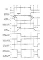
次に、図7に示すタイムチャートを参照しつつ、遊技機1に外部電力が供給されていないときの電源供給制御部50におけるCPU電源供給制御部500の制御について説明する。
扉開閉検出センサ60は、前扉3の閉鎖を検出しているときOFFしている。したがって、前扉3が閉鎖しているとき、CPU電源供給制御部500のCR回路R1、C1のA点の電圧がhighであるため、NANDゲート521の両入力端子521a、521bにhigh信号が入力されて、出力端子521cからlow信号が出力されている。このとき、CR回路R2、C2のB点の電圧がlowであるため、NANDゲート522の両入力端子522a、522bにlow信号が入力され、その出力端子522cからhigh信号が出力されている。
Next, control of the CPU power
The door opening /
NANDゲート522の出力端子522cからhigh信号が出力されているときは、NANDゲート523は、その入力端子523aにNANDゲート521の出力端子521cから出力されているlow信号、入力端子523bにNANDゲート522の出力端子522cから出力されているhigh信号がそれぞれ入力されているため、その出力端子523cからhigh信号を出力している。又、OR回路524は、その入力端子524aにNANDゲート521の出力端子521cから出力されているlow信号、入力端子524bにNANDゲート522の出力端子522cから出力されているhigh信号がそれぞれ入力されているため、その出力端子524cからhigh信号を出力している。
When a high signal is output from the
これにより、AND回路525は、その両入力端子525a、525bにhigh信号が入力されて、その出力端子525cからバックアップ電源投入制御信号103ではないhigh信号を出力し、その信号がCPU電源切替部530のENBに入力されている。この結果、CPU電源切替部530は、遊技機1に外部電力が供給されているか否かに関係なく、OUTBからバックアップ電力を出力することはない。
As a result, the AND
扉開閉検出センサ60が前扉3の開放を検出して開信号102を出力すると、その時点(図7に示すa点)で、CR回路C1、R1の時定数に基づく時間T1(例えば、22msec)後に、A点の電圧がlowになる。このため、NANDゲート521は、時間T1経過した時点(図7に示すb点)で、両入力端子521a、521bにlow信号が入力されて、出力端子521cからhigh信号を出力する。出力端子521cからhigh信号が出力されると、NANDゲート522は、CR回路C2、R2のB点の電圧が時間T2(例えば、33msec)経過してhighに変化するまで、その出力端子522cからhigh信号の出力を継続する。そして、NANDゲート523は、NANDゲート521の出力端子521cからhigh信号が出力された時点で、その出力端子523cからlow信号を出力する。
When the door opening /
NANDゲート523の出力端子523cからlow信号が出力されると、ANDゲート525は、その入力端子525aにhigh信号、入力端子525bにlow信号がそれぞれ入力されて、出力端子525cからバックアップ電源投入制御信号103をなすlow信号を出力し、その信号をCPU電源切替部530のENBに入力する。これにより、CPU電源切替部530は、OUTBからバックアップ電力を出力する。
When a low signal is output from the
そして、CPU電源切替部530のOUTBからバックアップ電力を出力してから、時間T2が経過すると、その時点(図7に示すc点)で、CR回路R2,C2のB点の電圧がhighになるため、NANDゲート522は、その両入力端子522a、522bにhigh信号が入力されて、出力端子522cからlow信号を出力する。これにより、NANDゲート523は、その入力端子523bにlow信号が入力されて、出力端子523cからhigh信号を出力する。
Then, after the backup power is output from OUTB of the CPU power
NANDゲート523の出力端子523cからhigh信号が出力されると、ANDゲート525は、その入力端子525a、525bにhigh信号がそれぞれ入力されて、出力端子525cからhigh信号を出力する。これを契機に、CPU電源切替部530は、OUTBからのバックアップ電力の出力を停止する。
When the high signal is output from the
CPU52は、CPU電源供給制御部500のCPU電源切替部530からバックアップ電力が供給されたことを契機に起動して、遊技機1に外部電力が供給されていないときに遊技機1に異常状態が発生したものと見做して、扉開閉検出センサ60から出力された開信号102を受けたときの日時を時計モジュール56から読み取ってRAM53に記憶させるとともに、そのときの電力源がバックアップ電力である旨の電力供給源情報をもRAM53に記憶させ、時間T2経過後に停止する。
The CPU 52 starts when the backup power is supplied from the CPU power
なお、遊技機1に外部電力が供給されていないとき、CPU52に供給されるバックアップ電力は、前扉3が開放している時間に関係なく、CPU52がRAM51に前扉3の開閉情報を記憶させるだけに必要な時間T2だけであるので、前扉3が長時間、開放された状態にあっても、バックアップ電源55の電力が無駄に消費されることはない。
Note that when external power is not supplied to the gaming machine 1, the backup power supplied to the CPU 52 causes the CPU 52 to store the opening / closing information of the
前扉3が開放状態から閉じられると、その時点(図7に示すd点)で、扉開閉検出センサ60がONからOFFに切り替わって閉信号102を出力すると、CR回路C1、R1の時定数に基づく時間T1後に、A点の電圧がhighになる。このため、NANDゲート521は、時間T1経過した時点(図7に示すe点)で、両入力端子521a、521bにhigh信号が入力されて、出力端子521cからlow信号を出力する。出力端子521cからlow信号が出力されると、NANDゲート522は、CR回路C2、R2のB点の電圧が時間T2経過してlowに変化するまでの期間、その出力端子522cからlow信号の出力を継続する。そして、ORゲート524は、NANDゲート521の出力端子521cからlow信号が出力された時点で、その出力端子524cからlow信号を出力する。
When the
ORゲート524の出力端子524cからlow信号が出力されると、ANDゲート525は、その入力端子525aにlow信号、入力端子525bにhigh信号がそれぞれ入力されて、出力端子525cからバックアップ電源投入制御信号103をなすlow信号を出力し、その信号をCPU電源切替部530のENBに入力する。これにより、CPU電源切替部530は、OUTBからバックアップ電力を出力する。
When a low signal is output from the
そして、CPU電源切替部530のOUTBからバックアップ電力を出力してから、時間T2が経過すると、その時点(図7に示すf点)で、CR回路R2,C2のB点の電圧がlowになるため、NANDゲート522は、その両入力端子522a、522bにlow信号が入力されて、出力端子522cからhigh信号を出力する。これにより、ORゲート524は、その入力端子524bにhigh信号が入力されて、出力端子524cからhigh信号を出力する。
Then, after the backup power is output from OUTB of the CPU power
ORゲート524の出力端子524cからhigh信号が出力されると、ANDゲート525は、その入力端子525a、525bにhigh信号がそれぞれ入力されて、出力端子525cからhigh信号を出力する。これを契機に、CPU電源切替部530は、OUTBからのバックアップ電力の出力を停止する。
When the high signal is output from the
CPU52は、CPU電源供給制御部500のCPU電源切替部530からバックアップ電力が供給されたことを契機に再び起動して、遊技機1に外部電力が供給されていないときに遊技機1に異常状態が発生したものと見做して、扉開閉検出センサ60から出力された閉信号102を受けたときの日時を時計モジュール56から読み取ってRAM53に記憶させるとともに、そのときの電力源がバックアップ電力である旨の電力供給源情報をもRAM53に記憶させ、時間T2経過後に停止する。
The CPU 52 is activated again when the backup power is supplied from the CPU power
次に、RAM53に記憶された開閉情報の確認方法について説明する。遊技機1に外部電力が供給されているとき、前扉3を開いて不正確認用操作スイッチ14を操作することにより、副制御基板5のCPU52によりRAM53に記憶された情報、例えば、前扉3が開放されたときの開日時情報201、前扉3が閉じられたときの閉日時情報202、遊技機1に外部電力が投入されたときの外部電源投入日時情報203、及び前扉3が開閉されたとき、CPU52に供給された電力が外部電力かバックアップ電力かを識別する電力供給源識別情報204を、表示装置9の表示画面91に、例えば、図8に示すように時系列に表示させて前扉3の開閉情報等を確認することができる。
Next, a method for confirming the opening / closing information stored in the
例えば、図8に示すように、外部電源投入日前に前扉3の開閉情報が表示装置9の表示画面91に表示された遊技機1は、不正が行われたおそれがあるものとして判断され、入念にチェックされるか、又は新たな遊技機と交換される。
For example, as shown in FIG. 8, it is determined that the gaming machine 1 in which the opening / closing information of the
上述により、本実施形態における遊技機は、次のような作用効果を奏する。
(a)遊技機1に外部電力が供給されていない電源遮断時に前扉3が開閉された場合、バックアップ電力供給により、CPU52がRAM53に前扉3が開放したとき及び閉鎖したときの日時情報をRAMに記憶させるため、RAM53に記憶された開閉情報に基づいて不正行為を監視することができ、セキュリティの向上を図ることができる。
As described above, the gaming machine according to the present embodiment has the following operational effects.
(A) When the
(b)CPU52にバックアップ電力を供給する時間は、CPU52がRAM53に開閉情報を記憶させるたけに必要な僅かな時間T2だけであるため、バックアップ電源55の消費電力を最小限に抑えることができ、遊技機1の電源遮断時における前扉3の不正な開閉を長期間監視することができ、バックアップ電源55の容量を小さくして、安価かつ小形のバックアップ電源55を用いることができる。
(B) Since the time for supplying the backup power to the CPU 52 is only a short time T2 necessary for the CPU 52 to store the open / close information in the
(c)外部電源遮断時、前扉3が長時間開いた状態にあっても、CPU52へのバックアップ電力供給時間は、時間T2だけであるため、バックアップ電源55の消費電力を最小限に抑えることができる。
(C) Even when the
(d)電源供給制御部50のRAM電源供給制御部550は、遊技機1に外部電力が供給されていないとき、バックアップ電力をRAM53及び時計モジュール56に供給し、又、遊技機1に外部電力が供給されたとき、バックアップ電力の供給を停止して、外部電力をRAM53及び時計モジュール56に供給するように切り替わるため、バックアップ電源55の電力消費を抑えることができる。
(D) The RAM power
以上、本発明の実施形態について説明したが、本発明の要旨を逸脱しない範囲内で、本実施形態に対して、次のような種々の変形や変更を施すことが可能である。
(i)遊技機1を、遊技媒体がメダル(コインを含む)とするスロットマシンに代えて、遊技媒体がパチンコ玉であるパチンコ機、スロットマシン、及びその他の遊技機とする。
(ii)扉開閉検出センサ60を、機械式のリミットスイッチに代えて、光電式等の非接触形のセンサとする。
(iii)開閉情報を表示させる表示装置としては、上記実施形態のように、前扉3の前面に開閉情報を表示させる表示装置9に代えて、前扉3の裏面又は筐体2内に、開閉情報表示専用の表示装置を別に設ける。
(iv)異常状態検出センサを、前扉3の開閉を検出する扉開閉検出センサ60に代えて、またはそれに加えて、他の異常状態を検出するものとする。他の異常状態としては、主制御基板4を収容した基板ボックスの脱着、遊技機1の移動等により生じる遊技機1の異常な傾きや振動、及び筐体2内への不正用具の挿入等による異常な圧力負荷の検出等がある。
Although the embodiment of the present invention has been described above, the following various modifications and changes can be made to the present embodiment without departing from the gist of the present invention.
(I) The gaming machine 1 is a pachinko machine in which the gaming medium is a pachinko ball, a slot machine, and other gaming machines, instead of a slot machine in which the gaming medium is a medal (including coins).
(Ii) The door opening /
(Iii) As a display device that displays open / close information, instead of the
(Iv) The abnormal state detection sensor detects another abnormal state instead of or in addition to the door open /
1 遊技機
2 筐体
2a 後板
3 前扉
3a 受皿
4 主制御基板
5 副制御基板
6 回転リールユニット
7 ホッパーユニット
8 外部電源供給装置
9 表示装置
10 中継基板
11 スピーカ
12 メダルセレクター
13 フック
14 異常確認用操作スイッチ
15 情報表示窓
16 遊技情報表示操作スイッチ
17 識別情報表示窓
18 メダル投入部
19 MAXベットボタン
20 1ベットボタン
21 スタートレバー
22 ストップボタン
23 精算ボタン
24 キーシリンダ
25 リセットスイッチ
26 メダル検出センサ
27 ランプ
50 電源供給制御部
51 ROM
52 CPU(記憶制御部)
53 RAM(記憶手段)
54 I/Oポート
55 バックアップ電源
56 時計モジュール
60 扉開閉検出センサ(異常状態検出センサ)
61 回転リール
62 モータ駆動回路
65 DCV
91 表示画面
92 液晶制御基板
101 外部電源投入信号
102 開閉信号
103 バックアップ電源供給制御信号
201 開日時情報
202 閉日時情報
203 外部電源投入日時情報
204 電力供給源識別情報
500 CPU電源供給制御部
510 信号処理部
520 バックアップ電源投入制御信号生成部
521、522、523 NANDゲート
524 ORゲート
525 ANDゲート
530 CPU電源切替部
550 RAM電源供給制御部
560 RAM電源切替部
R1、R2 抵抗
C1、C2 コンデンサ
DESCRIPTION OF SYMBOLS 1
52 CPU (Storage Control Unit)
53 RAM (storage means)
54 I /
61
91
Claims (1)
前記遊技機に外部電力が供給されていないとき、前記筐体内に設けられる電子素子である記憶手段及び時計モジュールが動作するために必要な電力を供給可能なバックアップ電源と、
前記遊技機に前記外部電力が供給されていないとき、前記扉開閉検出センサが前記前扉の開を検出したことを契機に、前記前扉を開いている時間に関係無く、後記記憶制御部が前記記憶手段に後記日時情報を記憶させるために必要な時間である所定時間を計時するタイマと、
前記筐体内に設けられ、前記タイマが前記所定時間を計時している期間、前記バックアップ電源の電力を後記記憶制御部に供給し、前記所定時間の経過後、後記記憶制御部への前記バックアップ電源の電力供給を停止する電源供給制御部と、
前記筐体内に設けられ、前記電源供給制御部により前記バックアップ電源の電力が供給されたことを契機に起動して、前記所定時間内に、前記扉開閉検出センサからの開信号を受けたときの日時情報を前記記憶手段に記憶させる記憶制御部とを備え、
前記電源供給制御部は、前記遊技機に前記外部電力が供給されていないとき、電力を供給する必要がある前記記憶手段及び前記時計モジュールに前記バックアップ電源から電力を供給し、かつ前記外部電力が供給されることにより、前記記憶手段及び前記時計モジュールへの前記バックアップ電源からの電力の供給を停止して前記外部電力の供給に切り替え可能な電源切替部を含むことを特徴とする遊技機。 A door opening / closing detection sensor capable of detecting opening / closing of a front door provided to be openable / closable in a housing of the gaming machine;
When external power is not supplied to the gaming machine , a storage power source that is an electronic element provided in the housing and a backup power source that can supply power necessary for the operation of the clock module ;
When the external power is not supplied to the gaming machine, the storage control unit described later is triggered by the door opening / closing detection sensor detecting the opening of the front door, regardless of the opening time of the front door. A timer for measuring a predetermined time, which is a time necessary for storing postscript date and time information in the storage means ;
The backup power source is provided in the housing and supplies power of the backup power source to a later-described storage control unit while the timer is counting the predetermined time, and after the elapse of the predetermined time, the backup power source to the later-described storage control unit A power supply control unit for stopping the power supply of
When the power supply control unit is provided in the housing and is activated when the power of the backup power source is supplied by the power supply control unit, and when an open signal is received from the door open / close detection sensor within the predetermined time and a storage control unit for storing time information in the storage means,
The power supply control unit supplies power from the backup power source to the storage means and the timepiece module that need to supply power when the external power is not supplied to the gaming machine, and the external power is A gaming machine comprising: a power supply switching unit capable of switching to supply of external power by stopping supply of power from the backup power supply to the storage means and the timepiece module when supplied.
Priority Applications (1)
| Application Number | Priority Date | Filing Date | Title |
|---|---|---|---|
| JP2007031283A JP5284591B2 (en) | 2007-02-09 | 2007-02-09 | Game machine |
Applications Claiming Priority (1)
| Application Number | Priority Date | Filing Date | Title |
|---|---|---|---|
| JP2007031283A JP5284591B2 (en) | 2007-02-09 | 2007-02-09 | Game machine |
Publications (3)
| Publication Number | Publication Date |
|---|---|
| JP2008194184A JP2008194184A (en) | 2008-08-28 |
| JP2008194184A5 JP2008194184A5 (en) | 2009-12-24 |
| JP5284591B2 true JP5284591B2 (en) | 2013-09-11 |
Family
ID=39753692
Family Applications (1)
| Application Number | Title | Priority Date | Filing Date |
|---|---|---|---|
| JP2007031283A Expired - Fee Related JP5284591B2 (en) | 2007-02-09 | 2007-02-09 | Game machine |
Country Status (1)
| Country | Link |
|---|---|
| JP (1) | JP5284591B2 (en) |
Families Citing this family (1)
| Publication number | Priority date | Publication date | Assignee | Title |
|---|---|---|---|---|
| JP2013022107A (en) * | 2011-07-19 | 2013-02-04 | Olympia:Kk | Game machine |
Family Cites Families (2)
| Publication number | Priority date | Publication date | Assignee | Title |
|---|---|---|---|---|
| JPH11109865A (en) * | 1997-10-01 | 1999-04-23 | Sanki System Engineering Kk | Sealing seal |
| JP2005312793A (en) * | 2004-04-30 | 2005-11-10 | Toyomaru Industry Co Ltd | Monitoring system and game machine equipped with same |
-
2007
- 2007-02-09 JP JP2007031283A patent/JP5284591B2/en not_active Expired - Fee Related
Also Published As
| Publication number | Publication date |
|---|---|
| JP2008194184A (en) | 2008-08-28 |
Similar Documents
| Publication | Publication Date | Title |
|---|---|---|
| JPWO2007122935A1 (en) | Game machine | |
| JP4945266B2 (en) | Game machine | |
| JP2008206588A (en) | Game machine | |
| JP2008206689A (en) | Game machine | |
| JP2008194382A (en) | Game machine | |
| JP2008264378A (en) | Game machine | |
| US8597105B2 (en) | Gaming machine | |
| JPWO2007129593A1 (en) | Game machine | |
| JP2008206790A (en) | Game machine | |
| JP2008284007A (en) | Game machine | |
| JP4612888B2 (en) | Game machine | |
| JP5284591B2 (en) | Game machine | |
| JP2006218091A (en) | Game machine | |
| JP5423249B2 (en) | Game machine | |
| JP2005342020A (en) | Door monitoring device | |
| JP5090011B2 (en) | Game machine | |
| JP5620098B2 (en) | Game machine | |
| JP5874766B2 (en) | Game machine | |
| JP5323319B2 (en) | Game machine | |
| JP4803704B2 (en) | Game machine | |
| JPWO2007122937A1 (en) | Game machine | |
| JP4548079B2 (en) | Game machine | |
| JP5874714B2 (en) | Game machine | |
| JP2008188300A (en) | Game machine | |
| JP5487807B2 (en) | Game machine |
Legal Events
| Date | Code | Title | Description |
|---|---|---|---|
| A521 | Written amendment |
Free format text: JAPANESE INTERMEDIATE CODE: A523 Effective date: 20091109 |
|
| A621 | Written request for application examination |
Free format text: JAPANESE INTERMEDIATE CODE: A621 Effective date: 20091109 |
|
| A977 | Report on retrieval |
Free format text: JAPANESE INTERMEDIATE CODE: A971007 Effective date: 20111109 |
|
| A131 | Notification of reasons for refusal |
Free format text: JAPANESE INTERMEDIATE CODE: A131 Effective date: 20111115 |
|
| A521 | Written amendment |
Free format text: JAPANESE INTERMEDIATE CODE: A523 Effective date: 20120113 |
|
| A02 | Decision of refusal |
Free format text: JAPANESE INTERMEDIATE CODE: A02 Effective date: 20120821 |
|
| A521 | Written amendment |
Free format text: JAPANESE INTERMEDIATE CODE: A523 Effective date: 20121114 |
|
| A911 | Transfer to examiner for re-examination before appeal (zenchi) |
Free format text: JAPANESE INTERMEDIATE CODE: A911 Effective date: 20121122 |
|
| A131 | Notification of reasons for refusal |
Free format text: JAPANESE INTERMEDIATE CODE: A131 Effective date: 20130205 |
|
| A521 | Written amendment |
Free format text: JAPANESE INTERMEDIATE CODE: A523 Effective date: 20130328 |
|
| TRDD | Decision of grant or rejection written | ||
| A01 | Written decision to grant a patent or to grant a registration (utility model) |
Free format text: JAPANESE INTERMEDIATE CODE: A01 Effective date: 20130528 |
|
| A61 | First payment of annual fees (during grant procedure) |
Free format text: JAPANESE INTERMEDIATE CODE: A61 Effective date: 20130530 |
|
| R150 | Certificate of patent or registration of utility model |
Ref document number: 5284591 Country of ref document: JP Free format text: JAPANESE INTERMEDIATE CODE: R150 |
|
| R250 | Receipt of annual fees |
Free format text: JAPANESE INTERMEDIATE CODE: R250 |
|
| R250 | Receipt of annual fees |
Free format text: JAPANESE INTERMEDIATE CODE: R250 |
|
| R250 | Receipt of annual fees |
Free format text: JAPANESE INTERMEDIATE CODE: R250 |
|
| R250 | Receipt of annual fees |
Free format text: JAPANESE INTERMEDIATE CODE: R250 |
|
| R250 | Receipt of annual fees |
Free format text: JAPANESE INTERMEDIATE CODE: R250 |
|
| LAPS | Cancellation because of no payment of annual fees |