JP5290077B2 - Biological model for training and manufacturing method of biological model for training - Google Patents
Biological model for training and manufacturing method of biological model for training Download PDFInfo
- Publication number
- JP5290077B2 JP5290077B2 JP2009170564A JP2009170564A JP5290077B2 JP 5290077 B2 JP5290077 B2 JP 5290077B2 JP 2009170564 A JP2009170564 A JP 2009170564A JP 2009170564 A JP2009170564 A JP 2009170564A JP 5290077 B2 JP5290077 B2 JP 5290077B2
- Authority
- JP
- Japan
- Prior art keywords
- training
- pseudo
- reduced diameter
- coronary artery
- diameter portion
- Prior art date
- Legal status (The legal status is an assumption and is not a legal conclusion. Google has not performed a legal analysis and makes no representation as to the accuracy of the status listed.)
- Expired - Fee Related
Links
- 238000004519 manufacturing process Methods 0.000 title claims abstract description 34
- 238000000034 method Methods 0.000 claims abstract description 39
- 208000031481 Pathologic Constriction Diseases 0.000 claims description 27
- 208000037804 stenosis Diseases 0.000 claims description 27
- 230000036262 stenosis Effects 0.000 claims description 25
- -1 polyethylene Polymers 0.000 claims description 18
- 230000000903 blocking effect Effects 0.000 claims description 13
- 238000010438 heat treatment Methods 0.000 claims description 13
- 239000004698 Polyethylene Substances 0.000 claims description 11
- 229920000573 polyethylene Polymers 0.000 claims description 11
- 229920001577 copolymer Polymers 0.000 claims description 8
- 229920005992 thermoplastic resin Polymers 0.000 claims description 6
- 229920000915 polyvinyl chloride Polymers 0.000 claims description 5
- 239000004800 polyvinyl chloride Substances 0.000 claims description 5
- 229920001971 elastomer Polymers 0.000 claims description 4
- 239000004677 Nylon Substances 0.000 claims description 3
- 239000000806 elastomer Substances 0.000 claims description 3
- 229920001778 nylon Polymers 0.000 claims description 3
- 229920003023 plastic Polymers 0.000 claims description 2
- 239000004033 plastic Substances 0.000 claims description 2
- 210000004351 coronary vessel Anatomy 0.000 abstract description 100
- 230000003902 lesion Effects 0.000 abstract description 23
- 239000000463 material Substances 0.000 abstract description 21
- 230000000704 physical effect Effects 0.000 abstract description 12
- 210000004204 blood vessel Anatomy 0.000 abstract description 11
- 239000008280 blood Substances 0.000 abstract description 2
- 230000010339 dilation Effects 0.000 abstract 2
- 210000001519 tissue Anatomy 0.000 description 25
- 230000001105 regulatory effect Effects 0.000 description 21
- 210000001367 artery Anatomy 0.000 description 17
- 230000002093 peripheral effect Effects 0.000 description 14
- 238000010586 diagram Methods 0.000 description 11
- 230000015572 biosynthetic process Effects 0.000 description 8
- 239000000470 constituent Substances 0.000 description 7
- 230000017531 blood circulation Effects 0.000 description 6
- 210000001105 femoral artery Anatomy 0.000 description 6
- 229920005989 resin Polymers 0.000 description 6
- 239000011347 resin Substances 0.000 description 6
- 229920002379 silicone rubber Polymers 0.000 description 6
- 239000000853 adhesive Substances 0.000 description 5
- 230000001070 adhesive effect Effects 0.000 description 5
- 239000012778 molding material Substances 0.000 description 5
- 238000010998 test method Methods 0.000 description 5
- XEEYBQQBJWHFJM-UHFFFAOYSA-N Iron Chemical compound [Fe] XEEYBQQBJWHFJM-UHFFFAOYSA-N 0.000 description 4
- 101100242901 Quaranfil virus (isolate QrfV/Tick/Afghanistan/EG_T_377/1968) PB2 gene Proteins 0.000 description 4
- 101150082826 Segment-2 gene Proteins 0.000 description 4
- 101100194052 Thogoto virus (isolate SiAr 126) Segment 2 gene Proteins 0.000 description 4
- 239000003822 epoxy resin Substances 0.000 description 4
- 229920000647 polyepoxide Polymers 0.000 description 4
- 239000004945 silicone rubber Substances 0.000 description 4
- 238000001356 surgical procedure Methods 0.000 description 4
- 239000004721 Polyphenylene oxide Substances 0.000 description 3
- 210000000709 aorta Anatomy 0.000 description 3
- 230000003247 decreasing effect Effects 0.000 description 3
- 238000005476 soldering Methods 0.000 description 3
- 230000002966 stenotic effect Effects 0.000 description 3
- 239000004696 Poly ether ether ketone Substances 0.000 description 2
- 229920000122 acrylonitrile butadiene styrene Polymers 0.000 description 2
- 210000000013 bile duct Anatomy 0.000 description 2
- HVYWMOMLDIMFJA-DPAQBDIFSA-N cholesterol Chemical compound C1C=C2C[C@@H](O)CC[C@]2(C)[C@@H]2[C@@H]1[C@@H]1CC[C@H]([C@H](C)CCCC(C)C)[C@@]1(C)CC2 HVYWMOMLDIMFJA-DPAQBDIFSA-N 0.000 description 2
- 238000007887 coronary angioplasty Methods 0.000 description 2
- 210000003748 coronary sinus Anatomy 0.000 description 2
- 239000005038 ethylene vinyl acetate Substances 0.000 description 2
- 239000012530 fluid Substances 0.000 description 2
- 239000010440 gypsum Substances 0.000 description 2
- 229910052602 gypsum Inorganic materials 0.000 description 2
- 229910052742 iron Inorganic materials 0.000 description 2
- 210000002751 lymph Anatomy 0.000 description 2
- 210000003101 oviduct Anatomy 0.000 description 2
- 230000007170 pathology Effects 0.000 description 2
- 229920001200 poly(ethylene-vinyl acetate) Polymers 0.000 description 2
- 229920003229 poly(methyl methacrylate) Polymers 0.000 description 2
- 229920001707 polybutylene terephthalate Polymers 0.000 description 2
- 229920000728 polyester Polymers 0.000 description 2
- 229920002530 polyetherether ketone Polymers 0.000 description 2
- 229920000139 polyethylene terephthalate Polymers 0.000 description 2
- 239000005020 polyethylene terephthalate Substances 0.000 description 2
- 229920000642 polymer Polymers 0.000 description 2
- 239000004926 polymethyl methacrylate Substances 0.000 description 2
- 229920006324 polyoxymethylene Polymers 0.000 description 2
- 229920006380 polyphenylene oxide Polymers 0.000 description 2
- 229920003225 polyurethane elastomer Polymers 0.000 description 2
- 208000037803 restenosis Diseases 0.000 description 2
- 210000003291 sinus of valsalva Anatomy 0.000 description 2
- 238000012360 testing method Methods 0.000 description 2
- 210000000626 ureter Anatomy 0.000 description 2
- 239000004925 Acrylic resin Substances 0.000 description 1
- 229920000178 Acrylic resin Polymers 0.000 description 1
- 235000008733 Citrus aurantifolia Nutrition 0.000 description 1
- 201000000057 Coronary Stenosis Diseases 0.000 description 1
- 206010011086 Coronary artery occlusion Diseases 0.000 description 1
- 206010011089 Coronary artery stenosis Diseases 0.000 description 1
- JOYRKODLDBILNP-UHFFFAOYSA-N Ethyl urethane Chemical compound CCOC(N)=O JOYRKODLDBILNP-UHFFFAOYSA-N 0.000 description 1
- 229920000106 Liquid crystal polymer Polymers 0.000 description 1
- 239000004977 Liquid-crystal polymers (LCPs) Substances 0.000 description 1
- 239000002033 PVDF binder Substances 0.000 description 1
- 229920008285 Poly(ether ketone) PEK Polymers 0.000 description 1
- 229930182556 Polyacetal Natural products 0.000 description 1
- 239000004952 Polyamide Substances 0.000 description 1
- 239000004962 Polyamide-imide Substances 0.000 description 1
- 239000004695 Polyether sulfone Substances 0.000 description 1
- 239000004697 Polyetherimide Substances 0.000 description 1
- 239000004642 Polyimide Substances 0.000 description 1
- 239000004734 Polyphenylene sulfide Substances 0.000 description 1
- 239000004743 Polypropylene Substances 0.000 description 1
- 239000004793 Polystyrene Substances 0.000 description 1
- 229920001328 Polyvinylidene chloride Polymers 0.000 description 1
- 101100247669 Quaranfil virus (isolate QrfV/Tick/Afghanistan/EG_T_377/1968) PB1 gene Proteins 0.000 description 1
- 101150025928 Segment-1 gene Proteins 0.000 description 1
- 101100242902 Thogoto virus (isolate SiAr 126) Segment 1 gene Proteins 0.000 description 1
- 235000011941 Tilia x europaea Nutrition 0.000 description 1
- XECAHXYUAAWDEL-UHFFFAOYSA-N acrylonitrile butadiene styrene Chemical compound C=CC=C.C=CC#N.C=CC1=CC=CC=C1 XECAHXYUAAWDEL-UHFFFAOYSA-N 0.000 description 1
- 239000004676 acrylonitrile butadiene styrene Substances 0.000 description 1
- 229920001893 acrylonitrile styrene Polymers 0.000 description 1
- 210000002159 anterior chamber Anatomy 0.000 description 1
- 125000003118 aryl group Chemical group 0.000 description 1
- 210000004369 blood Anatomy 0.000 description 1
- 210000002302 brachial artery Anatomy 0.000 description 1
- 210000000621 bronchi Anatomy 0.000 description 1
- 210000001715 carotid artery Anatomy 0.000 description 1
- 235000019994 cava Nutrition 0.000 description 1
- 210000001627 cerebral artery Anatomy 0.000 description 1
- 235000012000 cholesterol Nutrition 0.000 description 1
- 230000007423 decrease Effects 0.000 description 1
- 239000013013 elastic material Substances 0.000 description 1
- 230000005611 electricity Effects 0.000 description 1
- 210000003238 esophagus Anatomy 0.000 description 1
- 238000001125 extrusion Methods 0.000 description 1
- 229920001903 high density polyethylene Polymers 0.000 description 1
- 239000004700 high-density polyethylene Substances 0.000 description 1
- 229920000554 ionomer Polymers 0.000 description 1
- 210000002429 large intestine Anatomy 0.000 description 1
- 239000010410 layer Substances 0.000 description 1
- 210000005240 left ventricle Anatomy 0.000 description 1
- 239000004571 lime Substances 0.000 description 1
- 229920001684 low density polyethylene Polymers 0.000 description 1
- 239000004702 low-density polyethylene Substances 0.000 description 1
- 210000001365 lymphatic vessel Anatomy 0.000 description 1
- 239000007769 metal material Substances 0.000 description 1
- 230000003278 mimic effect Effects 0.000 description 1
- 229910001120 nichrome Inorganic materials 0.000 description 1
- 210000000277 pancreatic duct Anatomy 0.000 description 1
- 230000000149 penetrating effect Effects 0.000 description 1
- 239000005011 phenolic resin Substances 0.000 description 1
- 229920002492 poly(sulfone) Polymers 0.000 description 1
- 229920002647 polyamide Polymers 0.000 description 1
- 229920002312 polyamide-imide Polymers 0.000 description 1
- 229920001230 polyarylate Polymers 0.000 description 1
- 229920000515 polycarbonate Polymers 0.000 description 1
- 239000004417 polycarbonate Substances 0.000 description 1
- 229920000570 polyether Polymers 0.000 description 1
- 229920006393 polyether sulfone Polymers 0.000 description 1
- 229920001601 polyetherimide Polymers 0.000 description 1
- 229920001721 polyimide Polymers 0.000 description 1
- 229920000306 polymethylpentene Polymers 0.000 description 1
- 229920000098 polyolefin Polymers 0.000 description 1
- 229920000069 polyphenylene sulfide Polymers 0.000 description 1
- 229920001155 polypropylene Polymers 0.000 description 1
- 229920001296 polysiloxane Polymers 0.000 description 1
- 229920002223 polystyrene Polymers 0.000 description 1
- 229920001343 polytetrafluoroethylene Polymers 0.000 description 1
- 239000004810 polytetrafluoroethylene Substances 0.000 description 1
- 239000005033 polyvinylidene chloride Substances 0.000 description 1
- 229920002981 polyvinylidene fluoride Polymers 0.000 description 1
- SCUZVMOVTVSBLE-UHFFFAOYSA-N prop-2-enenitrile;styrene Chemical compound C=CC#N.C=CC1=CC=CC=C1 SCUZVMOVTVSBLE-UHFFFAOYSA-N 0.000 description 1
- 210000001147 pulmonary artery Anatomy 0.000 description 1
- 210000002254 renal artery Anatomy 0.000 description 1
- 210000005247 right atrial appendage Anatomy 0.000 description 1
- 210000005245 right atrium Anatomy 0.000 description 1
- 239000005060 rubber Substances 0.000 description 1
- 229920002050 silicone resin Polymers 0.000 description 1
- 239000002356 single layer Substances 0.000 description 1
- 210000000813 small intestine Anatomy 0.000 description 1
- 239000007787 solid Substances 0.000 description 1
- KKEYFWRCBNTPAC-UHFFFAOYSA-L terephthalate(2-) Chemical compound [O-]C(=O)C1=CC=C(C([O-])=O)C=C1 KKEYFWRCBNTPAC-UHFFFAOYSA-L 0.000 description 1
- 229920001187 thermosetting polymer Polymers 0.000 description 1
- 230000036962 time dependent Effects 0.000 description 1
- 210000003437 trachea Anatomy 0.000 description 1
- 210000003462 vein Anatomy 0.000 description 1
- 230000000007 visual effect Effects 0.000 description 1
Images











Landscapes
- Instructional Devices (AREA)
Abstract
Description
本発明は、訓練用生体モデルおよび訓練用生体モデルの製造方法に関する。 The present invention relates to a training biological model and a manufacturing method of the training biological model.
経皮的冠動脈形成術の一つとして、例えば、PTCA術(Percutaneous Transluminal Coronary Angioplasty:経皮的冠状動脈形成術)が知られている。 As one of the percutaneous coronary angioplasty, for example, PTCA (Percutaneous Transluminal Coronary Angioplasty) is known.
このPTCA術では、経大腿動脈法を適用した場合、次のような手技を経て、血管内の血流を回復させる。すなわち、I.まず、大腿動脈にシースカテーテルを挿入、次いで、これにガイドカテーテル用ガイドワイヤを挿入し、その先端を冠動脈入口付近まで進めた状態で、ガイドカテーテル用ガイドワイヤに沿わせてガイドカテーテルを進め、その先端を冠動脈口に位置させる。II.次に、ガイドカテーテル用ガイドワイヤを抜去し、バルーンカテーテル用ガイドワイヤをガイドカテーテル内に挿入して、ガイドカテーテルの先端からバルーンカテーテル用ガイドワイヤを突出させ、さらに冠動脈に生じている狭窄部位(病変部位)を越えた位置にまで進める。III.次に、バルーンカテーテル用ガイドワイヤを介してバルーンカテーテルを狭窄部位まで進め、バルーン部を狭窄部位に位置させた後、バルーンを膨張することにより狭窄部位すなわち血管壁を押し広げ、血液の通路を再形成して血流を回復させる。 In this PTCA technique, when the transfemoral artery method is applied, the blood flow in the blood vessel is recovered through the following procedure. That is, I.I. First, insert a sheath catheter into the femoral artery, then insert a guide catheter guide wire into the femoral artery, and advance the guide catheter along the guide catheter guide wire with its tip advanced to the vicinity of the coronary artery entrance. The tip is located at the coronary ostium. II. Next, the guide wire for the guide catheter is removed, the guide wire for the balloon catheter is inserted into the guide catheter, the guide wire for the balloon catheter is projected from the distal end of the guide catheter, and a stenotic site (lesion) occurring in the coronary artery Advance to a position beyond (part). III. Next, the balloon catheter is advanced to the stenosis site via the balloon catheter guide wire, and after the balloon portion is positioned at the stenosis site, the balloon is inflated to widen the stenosis site, that is, the blood vessel wall and re-open the blood passage. Form and restore blood flow.
以上のように、バルーンカテーテルを狭窄部位に位置させるには、複雑な工程を有し、術者には、極めて高度な技術が求められる。 As described above, in order to position the balloon catheter at the stenosis site, there are complicated steps, and the operator is required to have a very advanced technique.
そのため、近年、患者に対する手術の他に、術者の技術を向上さるための訓練に用いる生体モデルの開発が求められている。 Therefore, in recent years, in addition to surgery for patients, development of a biological model used for training for improving an operator's technique is required.
かかる生体モデルとして、血管やリンパ管のような管をモデルとした管モデルの製造方法が、例えば、特許文献1で提案されている。
As such a living body model, for example,
すなわち、特許文献1では、まず、CTスキャナやMRIスキャナ等の画像診断装置により得られた被検体の断層像データに基づき、この被検体の腔所領域を抽出してこの腔所領域に相当する内腔モデルを積層造形する。次に、この内腔モデルの周囲を立体モデル成形材料で囲繞した状態で立体モデル成形材料を硬化させた後、内腔モデルを除去することにより管モデル(立体モデル)を形成する。
That is, in
かかる構成の立体モデルでは、立体モデル成形材料としてシリコーンゴムやポリウレタンエラストマー等のような弾性材料が用いられ、管モデルは、血管やリンパ管の物理的性質に近似させて形成される。そして、この立体モデルは、内腔モデルを囲繞するようにして形成されるため、病変部位である狭窄部位も前記管と一体的に形成され、管と同様の物理的性質、すなわち、弾性を示すこととなる。しかしながら、例えば、血管に形成される狭窄部位は、主としてコレステロールが沈着したプラーク(沈着物)で構成されているため、その物理的性質は、血管とは大きく異なる。 In the three-dimensional model having such a configuration, an elastic material such as silicone rubber or polyurethane elastomer is used as the three-dimensional model molding material, and the tube model is formed by approximating the physical properties of blood vessels and lymph vessels. Since this three-dimensional model is formed so as to surround the lumen model, the stenosis site, which is a lesion site, is also formed integrally with the tube, and exhibits the same physical properties as the tube, that is, elasticity. It will be. However, for example, a stenosis site formed in a blood vessel is mainly composed of plaques (deposits) on which cholesterol is deposited, so that its physical properties are significantly different from those of blood vessels.
そのため、特許文献1に記載の立体モデルでは、狭窄部位に生じた実際のプラークの物理的性質に対応した訓練を実施できず、バルーンを狭窄部位で膨らませた後のプラークの状態が確認できないため、血液の流路の再構築がどのようになされているかを知ることができないという問題がある。
Therefore, in the three-dimensional model described in
本発明の目的は、訓練用生体モデルを用いて術者の技術向上を目的とする訓練を行う際に、訓練用生体モデルを実際の病変部の物理的性質に近似して訓練することができる訓練用生体モデル、および、かかる訓練用生体モデルを製造する訓練用生体モデルの製造方法を提供することにある。 An object of the present invention is to train a biological model for training by approximating physical properties of an actual lesion when performing training for improving the skill of an operator using the biological model for training. It is an object of the present invention to provide a training biological model and a training biological model manufacturing method for manufacturing the training biological model.
このような目的は、下記(1)〜(10)の本発明により達成される。
(1) 内腔部を有する管状体で構成され、管状組織を模した疑似管状組織を備え、
前記疑似管状組織は、ポリエチレン、ポリプロピレン、エチレン・酢酸ビニル共重合体、ナイロンエラストマー、軟質ポリ塩化ビニルおよびエチレン・プロピレン共重合体のうちの少なくとも1種の塑性変形可能な熱可塑性樹脂で構成され、その長手方向の途中が縮径して塑性変形したことにより縮径部が形成されており、
前記縮径部を管状組織に生じた狭窄部と見立て、該狭窄部に対し拡張を行なう拡張訓練に用いることを特徴とする訓練用生体モデル。
Such an object is achieved by the present invention of the following (1) to ( 10 ).
(1) It is composed of a tubular body having a lumen, and includes a pseudo-tubular tissue that imitates a tubular tissue,
The pseudo-tubular structure is composed of at least one plastically deformable thermoplastic resin of polyethylene, polypropylene, ethylene / vinyl acetate copolymer, nylon elastomer, soft polyvinyl chloride, and ethylene / propylene copolymer , The reduced diameter part is formed by reducing the diameter in the middle of the longitudinal direction and plastic deformation,
A living body model for training characterized in that the reduced diameter portion is regarded as a stenosis portion generated in a tubular tissue and used for expansion training for expanding the stenosis portion.
(2) 前記縮径部は、前記拡張訓練を行なったとき、その拡張により、拡張前の形状に戻らない程度に塑性変形するものである上記(1)に記載の訓練用生体モデル。 (2) The training biological model according to (1), wherein the reduced diameter portion is plastically deformed so as not to return to the shape before expansion when the expansion training is performed.
(3) 前記疑似管状組織は、熱収縮性を有し、
前記縮径部は、前記疑似管状組織を加熱することにより形成された部分である上記(1)または(2)に記載の訓練用生体モデル。
(3) The pseudo-tubular tissue has heat shrinkability,
The training biological model according to (1) or (2), wherein the reduced diameter portion is a portion formed by heating the pseudo tubular tissue.
(4) 前記疑似管状組織は、その長手方向に延伸可能であり、
前記縮径部は、前記疑似管状組織をその長手方向に沿って互いに反対方向に引張ることにより形成された部分である上記(1)または(2)に記載の訓練用生体モデル。
(4) The pseudo-tubular tissue can be stretched in the longitudinal direction,
The reduced diameter portion is the biological model for training according to the above (1) or (2), wherein the reduced diameter portion is a portion formed by pulling the pseudo-tubular tissue in the opposite direction along the longitudinal direction.
(5) 前記縮径部は、その内径が変化した部分を有する上記(1)ないし(4)のいずれかに記載の訓練用生体モデル。 ( 5 ) The living body model for training according to any one of (1) to ( 4 ), wherein the reduced diameter portion has a portion whose inner diameter is changed.
(6) 前記縮径部には、前記拡張訓練を行なった際、その一部が拡張するのを阻止する阻止部材が設置されている上記(1)ないし(5)のいずれかに記載の訓練用生体モデル。 ( 6 ) The training according to any one of (1) to ( 5 ), wherein a blocking member that prevents a part of the diameter-reducing portion from expanding when the expansion training is performed is installed. Biological model.
(7) 1種または2種以上の医療器具を、前記疑似管状組織内を挿通させて前記縮径部に到達させた後、該縮径部を拡張させる訓練に用いられる上記(1)ないし(6)のいずれかに記載の訓練用生体モデル。 (7) one or more medical instruments, after reaching the reduced diameter portion by inserting the pseudo-tubular tissue, the above (1) to be used in training to expand the reduced diameter portion ( The biological model for training according to any one of 6 ).
(8) 上記(1)ないし(7)のいずれかに記載の訓練用生体モデルを製造する方法であって、
前記疑似管状組織は、熱収縮性を有し、
前記疑似管状組織の途中を加熱することにより、前記縮径部を形成することを特徴とする訓練用生体モデルの製造方法。
( 8 ) A method of manufacturing the training biological model according to any one of (1) to ( 7 ) above,
The pseudo-tubular tissue has heat shrinkability,
A method for manufacturing a living body model for training, wherein the reduced diameter portion is formed by heating the middle of the pseudo tubular tissue.
(9) 上記(1)ないし(7)のいずれかに記載の訓練用生体モデルを製造する方法であって、
前記疑似管状組織は、その長手方向に延伸可能であり、
前記疑似管状組織をその長手方向に沿って互いに反対方向に引張ることにより、前記縮径部を形成することを特徴とする訓練用生体モデルの製造方法。
( 9 ) A method of manufacturing the training biological model according to any one of (1) to ( 7 ),
The pseudo-tubular tissue is stretchable in the longitudinal direction;
A method for producing a living body model for training, wherein the reduced diameter portion is formed by pulling the pseudo tubular tissue in opposite directions along the longitudinal direction thereof.
(10) 前記縮径部を形成する際、該縮径部の縮径の程度を規制する規制部材を用いる上記(8)または(9)に記載の訓練用生体モデルの製造方法。 ( 10 ) The method for producing a living body model for training according to ( 8 ) or ( 9 ) above, wherein when the reduced diameter portion is formed, a regulating member that restricts the degree of the reduced diameter of the reduced diameter portion is used.
本発明によれば、管状組織に生じる狭窄部の物理的性質に近似した縮径部を、疑似管状組織の任意の位置に任意の大きさ(形状)で配置することができる。そのため、この縮径部を備える訓練用生体モデルを用いて、さまざまな患者の病態に対応した訓練を実施できることから、術者は、患者に施す手術以外の場で、より高度な技術を習得することができる。 According to the present invention, the reduced diameter portion approximated to the physical property of the narrowed portion generated in the tubular tissue can be arranged at an arbitrary size (shape) in an arbitrary position of the pseudo tubular tissue. Therefore, since the training corresponding to various patient pathologies can be carried out using the training biological model having the reduced diameter portion, the surgeon learns more advanced techniques at a place other than the operation performed on the patient. be able to.
以下、本発明の訓練用生体モデルおよび訓練用生体モデルの製造方法を添付図面に示す好適な実施形態に基づいて詳細に説明する。
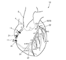
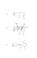
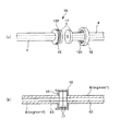
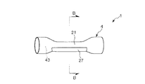
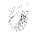
図1は、人体全身における動脈(心臓を含む)を示す模式図、図2は、図1に示す動脈を立体モデルに適用したものの全体写真、図3は、本発明の訓練用生体モデルが右冠動脈に配置された場合の実施形態(第1実施形態)を示す模式図、図4は、右冠動脈に配置された訓練用生体モデルに対してPTCA術の訓練を行う手順を示す図、図5は、本発明の訓練用生体モデルを示す縦断面図、図6は、訓練後の訓練用生体モデルの状態を示す縦断面図、図7〜図12は、それぞれ、本発明の訓練用生体モデルを製造する方法を説明するための図、図13〜図16は、それぞれ、本発明の訓練用生体モデルに対する接続方法を説明するための図、図17は、本発明の訓練用生体モデルの第2実施形態を示す斜視図、図18は、図17中のA−A線断面図、図19は、本発明の訓練用生体モデルの第3実施形態を示す斜視図、図20は、本発明の訓練用生体モデルの第4実施形態を示す斜視図、図21は、本発明の訓練用生体モデルの第5実施形態を示す斜視図、図22は、図21中のB−B線断面図、図23は、本発明の訓練用生体モデルが左冠動脈に配置された場合の実施形態(第6実施形態)を示す模式図、図24は、本発明の訓練用生体モデルの第6実施形態を示す縦断面、図25は、本発明の訓練用生体モデルが配置される、病変の好発部位を示すための図、図26は、疑似管状部材の材料特性を試験する試験方法を示す図、図27は、図26に示す試験方法で試験された疑似管状部材の材料特性(応力の経時的変化)を示すグラフである。なお、以下の説明では、図3〜図26中の上側を「上」、下側を「下」と言う。また、図3、図23および図25には、冠動脈の形状および位置等が分かり易くなるように、心臓の形状についても併せて図示している。
Hereinafter, a living body model for training and a manufacturing method of a living body model for training of the present invention will be described in detail based on preferred embodiments shown in the accompanying drawings.
FIG. 1 is a schematic diagram showing arteries (including the heart) in the whole human body, FIG. 2 is an overall photograph of the arteries shown in FIG. 1 applied to a three-dimensional model, and FIG. FIG. 4 is a schematic diagram showing an embodiment (first embodiment) when placed in a coronary artery, FIG. 4 is a diagram showing a procedure for performing PTCA surgery on a training biological model placed in the right coronary artery, and FIG. FIG. 6 is a longitudinal sectional view showing the state of the training biological model of the present invention, FIG. 6 is a longitudinal sectional view showing the state of the training biological model after training, and FIGS. FIG. 13 to FIG. 16 are diagrams for explaining the connection method to the training biological model of the present invention, and FIG. 17 is a diagram for explaining the training biological model of the present invention. The perspective view which shows 2 embodiment, FIG. 18 is the AA line in FIG. FIG. 19 is a perspective view showing a third embodiment of the living biological model for training of the present invention, FIG. 20 is a perspective view showing the fourth embodiment of the living biological model for training of the present invention, and FIG. The perspective view which shows 5th Embodiment of the biological model for training of invention, FIG. 22 is BB sectional drawing in FIG. 21, FIG. 23 is the case where the biological model for training of this invention is arrange | positioned in the left coronary artery FIG. 24 is a schematic view showing the sixth embodiment of the present invention, FIG. 24 is a longitudinal sectional view showing the sixth embodiment of the biological model for training of the present invention, and FIG. 25 is the biological model for training of the present invention. FIG. 26 is a diagram showing a site where lesions are likely to occur, FIG. 26 is a diagram showing a test method for testing the material characteristics of the pseudo-tubular member, and FIG. 27 is a material of the pseudo-tubular member tested by the test method shown in FIG. It is a graph which shows a characteristic (time-dependent change of stress). In the following description, the upper side in FIGS. 3 to 26 is referred to as “upper” and the lower side is referred to as “lower”. 3, 23, and 25 also illustrate the shape of the heart so that the shape and position of the coronary artery can be easily understood.
図2に示す立体モデルは、例えば、血管(動脈、静脈)、リンパ管、胆管、尿管、卵管等の管状組織を備えるヒトの生体の前記各種管状組織を再現して人工的に製造されたものである。この立体モデルを用いて、疑似病変部にバルーンカテーテル等の医療器具を到達させ、その後、疑似病変部を拡張することにより流路を確保したり、拡張した疑似病変部にステントを留置するための訓練等が実施される。以下では、動脈の形状に対応して形成された(管状組織を模した)疑似管状組織に、当該動脈に生じた病変部を模した疑似病変部を配置した(設けた)場合を一例に説明する。 The three-dimensional model shown in FIG. 2 is artificially manufactured by reproducing the various tubular tissues of a human living body including tubular tissues such as blood vessels (arteries, veins), lymphatic vessels, bile ducts, ureters, and oviducts. It is a thing. Using this three-dimensional model, a medical device such as a balloon catheter is made to reach the pseudo-lesion, and then the pseudo-lesion is expanded to secure a flow path or to place a stent in the expanded pseudo-lesion Training is conducted. In the following, an example in which a pseudo-lesion that simulates a lesion occurring in the artery is provided (provided) in a pseudo-tubular tissue (simulating a tubular tissue) formed corresponding to the shape of the artery will be described. To do.
ヒトの全身における動脈(心臓を含む)は、図1の模式図に示すような形状をなしている。この動脈の形状に対応した立体モデルは、例えば、特許第3613568号公報の記載に基づいて、次のようにして製造される。 Arteries (including the heart) in the whole human body have a shape as shown in the schematic diagram of FIG. A three-dimensional model corresponding to the shape of the artery is manufactured as follows based on, for example, the description of Japanese Patent No. 3613568.
まず、動脈が備える腔部(血液の流路)の断層像データをCTスキャナ、MRIスキャナのような画像診断装置を用いて得た後、この動脈の内腔部に対応する断層像データに基づいて動脈の内腔部の形状をなす内腔モデルを積層造形する。 First, tomographic image data of a cavity (blood flow path) provided in an artery is obtained using an image diagnostic apparatus such as a CT scanner or an MRI scanner, and then based on the tomographic image data corresponding to the lumen of the artery. Then, a lumen model that forms the shape of the lumen of the artery is layered.
次に、内腔モデルの周囲を立体モデル成形材料で囲繞した状態で立体モデル成形材料を硬化させた後、内腔モデルを除去することにより、図2の全体写真に示すような、動脈の形状に対応した動脈モデル(立体モデル)が形成される。 Next, after hardening the three-dimensional model molding material in a state in which the periphery of the lumen model is surrounded by the three-dimensional model molding material, the lumen model is removed, and the shape of the artery as shown in the whole photograph of FIG. An arterial model (three-dimensional model) corresponding to is formed.
上記のような動脈モデルが備える各部の動脈(モデル)、例えば、冠動脈、脳動脈、頸動脈、腎動脈、上腕動脈等の任意の位置に、疑似病変部を配置することにより、バルーンカテーテル等の医療器具を疑似病変部(狭窄モデル)に位置させた後、この疑似病変部を拡張することにより流路を確保する訓練を行うことができる。本実施形態では、訓練用生体モデル1は、動脈モデルが備える冠動脈(疑似管状組織)10に疑似病変部(疑似狭窄部)21を配置したものとなっている。
By placing a pseudo-lesioned part at an arbitrary position such as a coronary artery, a cerebral artery, a carotid artery, a renal artery, a brachial artery, etc. After the medical instrument is positioned at the pseudo-lesioned portion (stenosis model), training to secure the flow path can be performed by expanding the pseudo-lesioned portion. In the present embodiment, the living
冠動脈10は、大動脈5のバルサルバ洞において、左右に分岐する左冠動脈3および右冠動脈4からなる。
The
右冠動脈4は、バルサルバ洞窟の1つである右冠動脈洞の上部より前方に出た後、右心耳に覆われて右心房と肺動脈の間を走行し、右房室間溝に沿って鋭縁部41を回り後下行枝42に向かい、後室間溝で左心室後壁および中隔の下側を養う血管を派生する。
The right
なお、この右冠動脈4において、右冠動脈4の入口から鋭縁部41までを半分にした上半分をSegment1(#1:Proximal)といい、その下半分をSegment2(#2:Middle)といい、鋭縁部41から後下行枝42で分岐するまでをSegment3(#3:distal)という。また、後下行枝42の分岐以降をSegment4といい、このSegment4は、#4AV・#4PD・#4PLの3つに分けられる。
In the right
また、左冠動脈3は、バルサルバ洞の1つである左冠動脈洞の上部より左前方に出て、前室間溝に入る左前下行枝31と、左回旋枝32とに分岐する。
The left
なお、大動脈5から左前下行枝31と左回旋枝32とに分岐するまでの間の部位を左主幹部33(Segment5)という。また、左前下行枝31は、Segment6〜10まで細分化されており、このうち左前下行枝31の本幹は、Segment6(#6:Proximal)、Segment7(#7:Middle)、Segment8(#8:distal)の3つに分類され、Segment6とSegment7との間からSegment9(#9:第1対角枝)が分岐し、Segment7とSegment8との間からSegment10(#10:第2対角枝)が分岐している。さらに、左回旋枝32は、Segment11〜15まで細分化されており、このうち左回旋枝32の本幹は、Segment11(#11:Proximal)、Segment13(#13:distal)の2つに分類され、Segment11とSegment13との接続部からSegment12(#12:obtuse marginal branch;OM)が分岐している。
A portion from the aorta 5 to the branch to the left
<<第1実施形態>>
図4、図5に示す第1実施形態の訓練用生体モデル1は、冠動脈10の右冠動脈4(Segment2)と、右冠動脈4に配置された疑似病変部21と、右冠動脈4の双方の端部にそれぞれ設けられた接続部11とを備えている。右冠動脈4では、各接続部11を介して、Segment2の端部がそれぞれSegment1、Segment3と接続されている。この場合、各接続部11は、それぞれ、Segment1およびSegment3に対し着脱自在に構成されているのが好ましい。
<< First Embodiment >>
The training
また、かかる位置に配置された疑似病変部21に対して、PTCA術の訓練が行われるが、かかる訓練は、以下に示すような手順で実施される。
In addition, PTCA training is performed on the
[1] まず、大腿動脈にシースカテーテル(図示せず)を挿入、次いで、これにガイドカテーテル用ガイドワイヤ(図示せず)を挿入し、その先端を右冠動脈4の入口付近にまで進めた状態で、ガイドカテーテル用ガイドワイヤに沿わせてガイドカテーテル61を進め、その先端を右冠動脈4の入口に位置させる(図4(a)参照。)。
[1] First, a sheath catheter (not shown) is inserted into the femoral artery, then a guide catheter guide wire (not shown) is inserted into the femoral artery, and the distal end is advanced to the vicinity of the entrance of the right
[2] 次に、ガイドカテーテル用ガイドワイヤを抜去し、バルーンカテーテル用ガイドワイヤ62をガイドカテーテル61内に挿入してガイドカテーテル61の先端からバルーンカテーテル用ガイドワイヤ62を突出させ、さらに右冠動脈4に配置した疑似病変部21を越えた位置にまでバルーンカテーテル用ガイドワイヤ62を進める(図4(b)参照。)。
[2] Next, the guide
[3] 次に、バルーンカテーテル用ガイドワイヤ62の基端(大腿動脈)側から挿通されたバルーンカテーテル63の先端部をガイドカテーテル61の先端から突出させ、さらにバルーンカテーテル用ガイドワイヤ62に沿って進め、バルーンカテーテル63のバルーン64を疑似病変部21に位置させた後、バルーン64に、バルーンカテーテル63の基端側からバルーン膨張用の流体を注入することにより、バルーン64が膨張される(図4(c)参照。)。これにより、疑似病変部21が押し広げられる。
[3] Next, the distal end portion of the
[4] 次に、バルーンカテーテル63の基端側からバルーン膨張用の流体を排出し、図4(d)に示すようにバルーン64を収縮させる。その後、バルーンカテーテル用ガイドワイヤ62、バルーンカテーテル63、ガイドカテーテル61およびシースカテーテルを大腿動脈側から抜去する。これにより、疑似病変部21に血流路が形成される。
[4] Next, the balloon inflation fluid is discharged from the proximal end side of the
図5(図6についても同様)に示すように、右冠動脈4は、内腔部43を有する管状体で構成されたものである。そして、右冠動脈4の長手方向の途中には、その内径および外径が縮径した縮径部が形成されている。この縮径部を動脈(血管)に生じた狭窄部と見立てることができ、よって、当該縮径部は、狭窄部に対し拡張を行なう拡張訓練に用いられる疑似病変部21となる。
As shown in FIG. 5 (the same applies to FIG. 6), the right
右冠動脈4は、塑性変形可能な材料で構成されており、その材料としては、特に限定されず、ポリエチレン、ポリプロピレン、エチレン・酢酸ビニル共重合体、ナイロンエラストマー、軟質ポリ塩化ビニル、エチレン・プロピレン共重合体のような熱可塑性樹脂等が挙げられ、これらのうちの1種または2種以上を組み合わせて用いることができる。また、これらの熱可塑性樹脂のなかでも、特に、ポリエチレンを用いるのが好ましい。この場合、低密度ポリエチレン、高密度ポリエチレンのように、密度すなわち結晶化度が異なるもの同士を混合した樹脂も用いることができる。また、ポリエチレンで構成される右冠動脈4の硬度は、ショアA(JIS K6253に規定)が20〜80であるのが好ましく、25〜35であるのがより好ましい。破断強度は、5〜30MPaであるのが好ましく、8〜12MPaであるのがより好ましい。破断伸びは、100〜600%程度であるのが好ましく、100〜200%程度であるのがより好ましい。
The right
このようなポリエチレンを用い、右冠動脈4の母材となる管状体40が熱収縮性を有するように成形される。次に、図7〜図12に示すように、右冠動脈4に疑似病変部21を形成する際、管状体40の疑似病変部21を形成したい病変部形成領域20に対し、加熱または引張りを施すことにより、病変部形成領域20が縮径して、疑似病変部21が確実に形成される。また、このような縮径部で構成された疑似病変部21に対し拡張訓練をした際、それにより疑似病変部21が拡張変形する(拡径する)。そして、拡張変形した疑似病変部21は、拡張前の形状に戻らない程度に塑性変形したものとなっており(実質的に疑似病変部21は消失し)、よって、その変形状態(拡張状態)が確実に維持される(図4参照)。また、管状体40がポリエチレンで構成されていることにより、当該管状体40を例えば押出成形によって容易に成形することができる。
Using such polyethylene, the
また、右冠動脈4を構成する塑性変形可能な材料、すなわち、熱可塑性樹脂は、応力緩和率が好ましくは20〜60%、より好ましくは20〜30%となる材料特性を有するものである。
In addition, the plastically deformable material constituting the right
ここで、「応力緩和率」とは、管状体40を、常温で、図26に示す試験方法により得られた(定義された)ものである。
Here, the “stress relaxation rate” is obtained (defined) for the
まず、図26(a)に示すように、管状体40を短冊403にして、当該短冊403は、その一端(図中左側)が固定されて固定端401となり、他端(図中右側)が自由端402となっている。また、このときの短冊403は、全長がLとなっている。
First, as shown in FIG. 26A, the
次に、図26(a)に示す状態から、短冊403の自由端402を所定の速度(引張り速度)で図中右側(長手方向)へ引張る(図26(b)参照)。このときの条件は、1分間で全長が2Lとなるように引張る。全長が2Lとなったときの初期引張り応力をf0とする(図26(b)参照)。
Next, from the state shown in FIG. 26A, the
次に、図26(b)に示す状態から速度(引張り速度)を零にして全長2Lを保持する。そして、前記速度を零にしてから5分後の引張り応力をftとする(図26(c)参照)。 Next, the speed (pulling speed) is set to zero from the state shown in FIG. Then, the tensile stress after 5 minutes of the velocity to zero and f t (see FIG. 26 (c)).
そこで、「応力緩和率」を((f0−ft)/f0)×100で表すことができるものとする。 Therefore, it is assumed that can represent a "stress relaxation ratio" in ((f 0 -f t) / f 0) × 100.
応力緩和率がこのような数値範囲内にあることにより、拡張訓練をした際に、疑似病変部21(右冠動脈4)は、より確実に変形し、よって、実際のヒトの動脈に近似したものとなる。これにより、拡張訓練を行なうと、その訓練があたかも実際の手技(PTCA術)を行なっているのと同様の感覚を得る。なお、応力緩和率の大きさの調整は、例えば、構成材料を適宜選択したり、分子量や分子構造(結晶化度)を変えたりすること等により、行なうことができる。 Since the stress relaxation rate is within such a numerical range, the pseudo-lesioned part 21 (the right coronary artery 4) is more reliably deformed during expansion training, and thus approximates to an actual human artery. It becomes. Thereby, when extended training is performed, the same feeling as if the training is performing an actual procedure (PTCA technique) is obtained. The magnitude of the stress relaxation rate can be adjusted, for example, by appropriately selecting a constituent material or changing the molecular weight or molecular structure (crystallinity).
また、右冠動脈4の周方向の引張弾性率は、0.5〜50MPaであるのが好ましく、0.5〜5.0MPaであるのがより好ましい。
Further, the tensile elastic modulus in the circumferential direction of the right
また、右冠動脈4では、疑似病変部21が形成されている以外の部分は、その内径φd1および外径φd2がそれぞれ長手方向に沿って一定となっている。このような右冠動脈4は、比d2/d1が1.01〜2なる関係を満足するものが好ましく、比d2/d1が1.01〜1.2なる関係を満足するものがより好ましい。さらに、右冠動脈4(Segment2)の内径φd1は、2〜5mm程度に設定するのが好ましい。
Also, the right
疑似病変部21の最小内径φd3は、特に限定されないが、(φd1−φd3)/φd1が50〜100%となるようにφd3を設定するのが好ましい。疑似病変部21の最小内径φd3をかかる範囲内に設定することにより、実際の狭窄部位の狭窄度に適した訓練を確実に実施することができ、術者の技術向上が的確に図られる。
The minimum inner diameter φd 3 of the
また、疑似病変部21の長さは、特に限定されないが、1〜100mm程度であるのが好ましく、5〜50mm程度であるのがより好ましい。疑似病変部21の長さをかかる範囲内に設定することにより、より実際の病変部位(狭窄部位)の大きさに適した訓練を実施することができる。
Further, the length of the
疑似病変部21の両端部には、それぞれ、その内面が傾斜した、すなわち、その内径が内部側から外部側に向かって漸増した傾斜面(テーパ面)22が形成されている。これにより、前記工程[3]において、バルーン64を疑似病変部21に到達させる際に、疑似病変部21の傾斜面22にバルーンカテーテル63を沿わせることができ、よって、その操作を容易かつ確実に行なうことができる。なお、傾斜面22は、特に限定されないが、右冠動脈4の中心軸に対して、15°〜65°程度の角度で傾斜しているのが好ましく、22°〜55°程度の角度で傾斜しているのがより好ましい。これにより、実際の狭窄部位の形状により適した訓練を確実に実施することができる。
At both end portions of the
次に、訓練用生体モデル1(立体モデル)を用いてPTCA術の訓練を行なった際の、当該訓練用生体モデル1の状態について詳細に説明する。
Next, the state of the living
訓練用生体モデル1を用いてPTCA術の訓練を行なうと、図4(c)に示す前記工程[3]では、膨張したバルーン64により、疑似病変部21が外方に向かって押圧される。これにより、疑似病変部21が拡張して変形し、当該疑似病変部21が実質的に消失する。
When PTCA training is performed using the training
そして、図4(d)に示す前記工程[4]で、バルーンカテーテル用ガイドワイヤ62およびバルーンカテーテル63を疑似病変部21から取り外した後は、疑似病変部21は、前述したように塑性変形するものであるため、拡張前の形状に戻らずに、前記拡張して変形した状態、すなわち、バルーン64で押し広げた形状を維持していることとなる。これは、実際にヒトの右冠動脈に生じた狭窄部に対しPTCA術を施した場合に、狭窄部が拡張した状態となるのとほぼ同じ現象となっている。
Then, after removing the balloon
このように、訓練用生体モデル1を用いることにより、術者の技術向上を目的とする訓練を行う際、訓練用生体モデル1が実際の病変部の物理的性質に近似したものとなっているため、実地の手技に則した訓練を確実に行なうことができる。
Thus, by using the
また、前記工程[3]におけるバルーン64の拡張、それによる疑似病変部21の拡張の度合いを、目視やX線造影像で観察しながら訓練を実施できるので、かかる観点からも、より質の高い訓練を実施することができる。
Moreover, since the training can be carried out while observing the degree of expansion of the
なお、前記工程[4]により血流が回復された後の疑似病変部21、すなわちPTCA術が施術された後の疑似病変部21に対して、図6に示すように、ステント81を留置することにより、疑似病変部21の再狭窄を防止することができる。このようなステント81を留置する治療の訓練にも訓練用生体モデル1を用いることができ、かかる訓練に訓練用生体モデル1を用いれば、再狭窄が好適に防止されているか否かの評価をより確実に実施することができる。
In addition, as shown in FIG. 6, the stent 81 is placed in the pseudo
以上のような構成の訓練用生体モデル1は、例えば、次のようにして、右冠動脈4のSegment2に疑似病変部21を形成することにより、製造することができる。ここでは、訓練用生体モデル1を製造する方法について説明する。
The training
<第1の製造方法>
まず、図7(a)に示すように、右冠動脈4となる母材としての管状体40を用意する。この管状体40は、前述したようにポリエチレンで構成され、熱収縮性を有している。
<First manufacturing method>
First, as shown in FIG. 7A, a
次に、図7(b)に示すように、例えばヘアドライヤ等のようなヒートガン100を用いて、管状体40(右冠動脈4)の病変部形成領域20に対し、例えば80〜120度の熱風を当てて当該病変部形成領域20を加熱する。そして、病変部形成領域20が縮径して、その大きさが所望の大きさとなったときに、加熱を停止する。これにより、疑似病変部21が形成された右冠動脈4を得る。
Next, as shown in FIG.7 (b), for example, 80-120 degree | times hot air is given with respect to the lesioned
なお、加熱の時間や温度によって、疑似病変部21の狭窄の程度を適宜変更することができる。
Note that the degree of stenosis of the
<第2の製造方法>
まず、図8(a)に示すように、管状体40を用意する。
<Second production method>
First, as shown in FIG. 8A, a
次に、図8(b)に示すように、例えば半田付けに用いられる半田ごて200を用いて、管状体40の病変部形成領域20に対し、例えば80〜120度に設定されたこて先201を当てて当該病変部形成領域20を加熱する。そして、病変部形成領域20が縮径して、その大きさが所望の大きさとなったときに、こて先201を病変部形成領域20から離間させる。これにより、疑似病変部21が形成された右冠動脈4を得る。
Next, as shown in FIG. 8 (b), for example, using a
<第3の製造方法>
図9(a)に示すように、管状体40を用意する。
<Third production method>
As shown in FIG. 9A, a
また、管状体40に挿通して用いられる一対の規制部材300を用意する。各規制部材300は、それぞれ、病変部形成領域20(疑似病変部21)の縮径の程度を規制するものである。一対の規制部材300は、同じ構成であるため、一方の規制部材300について代表的に説明する。規制部材300は、棒状をなし、その外径が変化した3つの部分、すなわち、小径部301と、大径部302と、小径部301と大径部302との間に位置する外径漸減部303とを有するものである。小径部301と大径部302とは、規制部材300の両端部に形成されている。外径漸減部303は、その外径が大径部302から小径部301に向かって漸減した部分である。小径部301は、疑似病変部21の最小内径φd3となる部分を形成するのを担い、外径漸減部303は、疑似病変部21の傾斜面22となる部分を形成するのを担う。また、大径部302は、右冠動脈4の疑似病変部21以外の部分を形成するのを担う。
In addition, a pair of regulating
図9(b)に示すように、各規制部材300をそれぞれ小径部301側から管状体40に挿入し、端面同士が当接した状態とする。このとき、管状体40の病変部形成領域20に、各小径部301を位置させる。
As shown in FIG. 9B, each regulating
次に、図9(c)に示すように、ヒートガン100を用いて、管状体40の全体に対し、例えば80〜120度の熱風を当てて当該管状体40を加熱する。
Next, as shown in FIG. 9C, the
そして、図9(d)に示すように、管状体40全体が縮径して、その内周面が各規制部材300の外周面に当接したときに、加熱を停止する。
And as shown in FIG.9 (d), when the diameter of the whole
次に、図9(e)に示すように、各規制部材300をそれぞれ抜去する。これにより、疑似病変部21が形成された右冠動脈4を得る。また、規制部材300を用いるため、疑似病変部21の縮径の程度が一定となり、均一な形状の右冠動脈4を量産することができる。
Next, as shown in FIG. 9E, each regulating
<第4の製造方法>
図10(a)に示すように、管状体40を用意する。
<Fourth manufacturing method>
As shown in FIG. 10A, a
また、管状体40に挿通して用いられる規制部材500を用意する。規制部材500は、病変部形成領域20(疑似病変部21)の縮径の程度を規制するものである。この規制部材500は、実際のヒトの右冠動脈の狭窄部付近の断層像データをCTスキャナ、MRIスキャナのような画像診断装置を用いて得た後、この断層像データに基づいて3次元プリンタにより造形されたものである。従って、規制部材500には、その外径が変化した外径変化部501が複数形成されている。そして、各外径変化部501は、それぞれ、疑似病変部21となる部分を形成するのを担うことができる。また、規制部材500は、光硬化性樹脂、石膏、シリコンゴム等で構成されている。
Further, a regulating
図10(b)に示すように、規制部材500を管状体40に挿入する。このとき、管状体40の病変部形成領域20に、各外径変化部501を位置させる。そして、この状態で、ヒートガン100を用いて、管状体40の全体に対し、例えば80〜120度の熱風を当てて当該管状体40を加熱する。
As shown in FIG. 10 (b), the regulating
そして、図10(c)に示すように、管状体40全体が縮径して、その内周面が各規制部材500の外周面に当接したときに、加熱を停止する。
And as shown in FIG.10 (c), when the diameter of the whole
次に、図10(d)に示すように、規制部材500を粉砕、溶解、延伸して、取り除く。これにより、内径が変化した疑似病変部21を有する右冠動脈4を得る。また、規制部材500を用いるため、均一な形状の右冠動脈4を量産することができる。
Next, as shown in FIG. 10D, the regulating
<第5の製造方法>
まず、図11(a)に示すように、管状体40を用意する。この管状体40は、前述したようにポリエチレンで構成され、その長手方向に延伸可能なものとなっている。
<Fifth manufacturing method>
First, as shown in FIG. 11A, a
次に、図11(b)に示すように、管状体40(右冠動脈4)の病変部形成領域20の両端部にそれぞれ鉗子400を装着する。そして、この状態で各鉗子400をそれぞれ把持して、管状体40をその長手方向に沿って互いに反対方向に引張る。
Next, as shown in FIG. 11B,
そして、図11(c)に示すように、この引張り操作により病変部形成領域20が伸長しつつ縮径して、その大きさが所望の大きさとなったときに、当該引張り操作を停止する。その後、各鉗子400をそれぞれ取り外す。これにより、疑似病変部21が形成された右冠動脈4を得る。
And as shown in FIG.11 (c), when the diameter of the lesion part formation area |
なお、引張り操作におけるその延伸の程度によって、疑似病変部21の狭窄の程度を適宜変更することができる。
Note that the degree of stenosis of the
<第6の製造方法>
図12(a)に示すうように、管状体40を用意する。
<Sixth manufacturing method>
A
また、管状体40に挿通して用いられる規制部材600を用意する。規制部材600は、病変部形成領域20(疑似病変部21)の縮径の程度を規制するものである。この規制部材600は、外径が長手方向に一定の棒状をなし、疑似病変部21の最小内径φd3となる部分を形成するのを担うことができる。
In addition, a regulating
図12(b)に示すように、規制部材600を管状体40に挿入する。
次に、図12(c)に示すように、前記第5の製造方法と同様の方法で、管状体40の病変部形成領域20をその長手方向に沿って互いに反対方向に引張る。そして、病変部形成領域20が伸長しつつ縮径して、その内周面(内面214)が規制部材600の外周面に当接したときに、引張り操作を停止する。
As shown in FIG. 12B, the regulating
Next, as shown in FIG. 12C, the lesioned
次に、図12(d)に示すように、規制部材600を抜去する。これにより、疑似病変部21が形成された右冠動脈4を得る。また、規制部材600を用いるため、疑似病変部21の縮径の程度が一定となり、均一な形状の右冠動脈4を量産することができる。
Next, as shown in FIG. 12D, the regulating
また、各接続部11は、Segment2である右冠動脈4をその両端部でそれぞれ着脱可能とするため、当該両端部にそれぞれ設けられている(図3参照)。すなわち、Segment2は、一端がSegment1の端部と、他端がSegment3の端部と、それぞれ、接続部11で接続され、これにより、右冠動脈4から着脱可能な構成となっている。
Moreover, each
このような接続部11は、Segment2の部分で着脱可能で、かつ接続すべき各端部同士を液密に接続し得る構成であれば、いかなる構成のものであってもよいが、例えば、以下に示すような接続形態により、液密に接続することができる。各接続部11は、互いに同じ構成であるため、以下、一方(Segment1側)の接続部11にいて説明する。
Such a
<第1の接続形態>
図13に示すように、接続具12は、その中心部に軸方向(長手方向)に貫通する貫通孔14を有し、その全体形状がほぼ筒状をなす本体13と、本体13の長手方向のほぼ中央に設けられたフランジ15とを有するものである。
<First connection configuration>
As shown in FIG. 13, the
本体13は、その両端部で外径が縮径する縮径部を有しており、この縮径部の外径が右冠動脈4の内径よりも小さく設定され、縮径部よりもフランジ15側(内側)ではその外径が右冠動脈4の内径よりも大きく設定される。
The
かかる構成の接続具12に対して、右冠動脈4の先端(切断面)から右冠動脈4を、前記先端部からフランジ15側に向かって挿入すると、右冠動脈4の内径が拡径する。これにより、本体13の外周面と右冠動脈4の内周面とが互いに密着することとなるため、接続具12により、右冠動脈4の端部同士が液密に接続される。
When the right
接続具12の構成材料としては、特に限定されないが、各種樹脂材料が好適に用いられ、具体的には、ポリエチレン、ポリプロピレン、エチレン−プロピレン共重合体、エチレン−酢酸ビニル共重合体(EVA)等のポリオレフィン、ポリ塩化ビニル、ポリ塩化ビニリデン、ポリスチレン、ポリアミド、ポリイミド、ポリアミドイミド、ポリカーボネート、ポリ−(4−メチルペンテン−1)、アイオノマー、アクリル系樹脂、ポリメチルメタクリレート、アクリロニトリル−ブタジエン−スチレン共重合体(ABS樹脂)、アクリロニトリル−スチレン共重合体(AS樹脂)、ブタジエン−スチレン共重合体、ポリエチレンテレフタレート(PET)、ポリブチレンテレフタレート(PBT)、ポリシクロヘキサンテレフタレート(PCT)等のポリエステル、ポリエーテル、ポリエーテルケトン(PEK)、ポリエーテルエーテルケトン(PEEK)、ポリエーテルイミド、ポリアセタール(POM)、ポリフェニレンオキシド、変性ポリフェニレンオキシド、ポリサルフォン、ポリエーテルサルフォン、ポリフェニレンサルファイド、ポリアリレート、芳香族ポリエステル(液晶ポリマー)、ポリテトラフルオロエチレンおよびポリフッ化ビニリデン等の各種樹脂材料が挙げられ、これらのうちの1種または2種以上を組み合わせて用いることができる。
Although it does not specifically limit as a constituent material of the
<第2の接続形態>
図14に示すように、接続機構16は、切断された右冠動脈4の各先端(切断面)に設けられたフランジ17と、一方の右冠動脈4に回転可能に支持されたリング状部材(第1のリング状部材)18と、他方の右冠動脈4にフランジ17と接触するように固着されたリング状部材(第2のリング状部材)19とを有するものである。
<Second connection form>
As shown in FIG. 14, the
リング状部材18には、フランジ17側に開放する開放部が形成されており、この開放部の内面には雌ネジ181が形成されている。
The ring-shaped
また、リング状部材19には、その外周面に雄ネジ191が形成され、さらに、このリング状部材19がリング状部材18に形成された開放部に挿入可能な大きさに設定されることにより、リング状部材19がリング状部材18の開放部に挿入(螺入)し得るようになっている。
In addition, the ring-shaped
かかる構成の接続機構16において、2つのフランジ17の端面同士を接触させた状態で、リング状部材18、19にそれぞれ形成された雌ネジ181と雄ネジ191とを螺合することにより、2つのフランジ17の端面同士が互いに密着することとなるため、接続機構16により、右冠動脈4の端部同士が液密に接続される。
In the
接続機構16の各種構成部材の構成材料としては、前述した接続具12の構成材料と同様のものが好適に用いられる。
As the constituent material of the various constituent members of the
<第3の接続形態>
図15(a)に示すように、Segment1側の右冠動脈4には、予めバーブ継ぎ手9が接続されている。バーブ継ぎ手9は、その接続部91の外径が段階的に変化したものである。
<Third connection configuration>
As shown in FIG. 15A, a
Segment2側の右冠動脈4の端部にバーブ継ぎ手9の接続部91を挿入し、この状態でヒートガン100を用いて、例えば80〜120度の熱風を当てて当該端部を加熱する(図15(b)参照)。そして、この端部が縮径して、接続部91に密着したときに、加熱を停止する(図15(c)参照)。これにより、バーブ継ぎ手9を介して、Segment1側の右冠動脈4とSegment2側の右冠動脈4とを確実に接続することができる。
The
<第4の接続形態>
図16に示すように、Segment2側の右冠動脈4の端部には、バーブ継ぎ手9の接続部91が挿入された状態となっている。また、右冠動脈4の端部の外周部には、電源に接続された電熱線700(例えばニクロム線)が巻回されている。この電熱線700に通電することにより、右冠動脈4の端部が縮径する。そして、当該端部が接続部91に密着したときに、通電を停止する。これにより、バーブ継ぎ手9を介して、Segment1側の右冠動脈4とSegment2側の右冠動脈4とを確実に接続することができる。
<Fourth connection type>
As shown in FIG. 16, the
なお、冠動脈10の右冠動脈4のSegment2を除く部分の構成材料としては、特に限定されないが、例えば、Segment2と同様の材料を用いることができる。また、この他、例えば、シリコーンエラストマー、シリコーンゲルのようなシリコーンゴム、ポリウレタンエラストマー、シリコーン樹脂、エポキシ樹脂、フェノール樹脂のような熱硬化性樹脂、ポリメタクリル酸メチル、ポリ塩化ビニル、ポリエチレンのような熱可塑性樹脂等が挙げられ、これらのうちの1種または2種以上を組み合わせて用いることができる。これらの中でも、特に、シリコーンゴムを用いるのが好ましい。
In addition, although it does not specifically limit as a constituent material of the part except Segment2 of the right
具体的には、シリコーンゴムで構成される冠動脈10の破断強度は、0.5〜3.0MPa程度であるのが好ましく、1.0〜2.0MPa程度であるのがより好ましい。
Specifically, the breaking strength of the
また、冠動脈10の破断伸びは、50〜300%程度であるのが好ましく、100〜200%程度であるのがより好ましい。
The breaking elongation of the
さらに、冠動脈10のショアA硬度(JIS K6253に規定)は、10〜40程度であるのが好ましく、25〜35程度であるのがより好ましい。
Furthermore, the Shore A hardness (specified in JIS K6253) of the
さらに、冠動脈10の引張弾性率は、0.01〜5.0MPa程度であるのが好ましく、0.1〜3.0MPa程度であるのがより好ましい。
Furthermore, the tensile elastic modulus of the
また、冠動脈10の内径は、特に限定されないが、0.5〜10.0mm程度に設定されるのが好ましく、1.0〜5.0mm程度に設定されるのがより好ましい。
The inner diameter of the
<<第2実施形態>>
ここでは、第2実施形態について説明するが、前述した実施形態との相違点を中心に説明し、同様の事項はその説明を省略する。
<< Second Embodiment >>
Here, although the second embodiment will be described, the description will focus on the differences from the above-described embodiment, and the description of the same matters will be omitted.
図17(a)に示すように、疑似病変部21には、その外周部の長手方向の中央部に、複数本の溝26が形成されている。これらの溝26は、疑似病変部21の長手方向に沿って形成され、疑似病変部21の周方向に沿って等角度間隔に配置されている。また、図18に示すように、各溝26の深さt1は、それぞれ、疑似病変部21の壁厚t2の1/10〜1/2程度であるのが好ましく、1/5〜1/3程度であるのがより好ましい。具体的は、深さt1を20〜100μmとすることができる。
As shown in FIG. 17A, a plurality of
このような溝26が形成されていることにより、図17(b)に示すように、拡張訓練を行なった際には、各溝26がそれぞれその幅が拡張し、その結果、疑似病変部21全体が確実に拡張することができる。これにより、実際の病変部の物理的性質に近似した拡張訓練を行なうことができ、よって、術者の技術向上が図れる。
Due to the formation of
なお、溝26の形成方法としては、特に限定されないが、例えば、刃物(例えばカッター、リューター)による方法、レーザ(例えばエキシマレーザ、CO2レーザ)による方法等が挙げられる。
The method for forming the
また、溝26は、疑似病変部21の長手方向に沿って形成されたものに限定されず、例えば、疑似病変部21の周方向に沿って形成されたものであってもよい。
また、溝26は、右冠動脈4の疑似病変部21以外の部分(端部)にまで延在してもよい。
Moreover, the groove |
Further, the
<<第3実施形態>>
ここでは、第3実施形態について説明するが、前述した実施形態との相違点を中心に説明し、同様の事項はその説明を省略する。
<< Third Embodiment >>
Here, the third embodiment will be described, but the description will focus on the differences from the above-described embodiment, and the description of the same matters will be omitted.
図19に示すように、複数本の溝26は、疑似病変部21の周方向の一部(図中上側の部分)に偏在して形成されている。このような疑似病変部21でも、拡張訓練を行なった際には、各溝26がそれぞれその幅が拡張し、その結果、疑似病変部21全体が確実に拡張することができる。これにより、実際の病変部の物理的性質に近似した拡張訓練を行なうことができ、よって、術者の技術向上が図れる。
As shown in FIG. 19, the plurality of
<<第4実施形態>>
ここでは、第4実施形態について説明するが、前述した実施形態との相違点を中心に説明し、同様の事項はその説明を省略する。
<< Fourth Embodiment >>
Here, although the fourth embodiment will be described, the description will focus on the differences from the above-described embodiment, and the description of the same matters will be omitted.
図20に示すように、複数本の溝26は、互いに交差し、疑似病変部21の周方向の一部(図中上側の部分)に偏在して形成されている。このような疑似病変部21でも、拡張訓練を行なった際には、各溝26がそれぞれその幅が拡張し、その結果、疑似病変部21全体が確実に拡張することができる。これにより、実際の病変部の物理的性質に近似した拡張訓練を行なうことができ、よって、術者の技術向上が図れる。
As shown in FIG. 20, the plurality of
<<第5実施形態>>
ここでは、第5実施形態について説明するが、前述した実施形態との相違点を中心に説明し、同様の事項はその説明を省略する。
<< Fifth Embodiment >>
Although the fifth embodiment will be described here, the description will focus on the differences from the above-described embodiment, and the description of the same matters will be omitted.
図21に示すように、疑似病変部21には、その外周部の周方向の一部(図中上側の部分)に偏在して、阻止部材27が固定的に設置されている。この阻止部材27は、拡張訓練を行なった際、疑似病変部21の阻止部材27が配置された部分が拡張するのを阻止するものである(図22参照)。このような疑似病変部21は、動脈に生じた狭窄部の中でも特に石灰化した狭窄部を模したものとなる。この疑似病変部21に対し、拡張訓練を行なうと、疑似病変部21は、図22(a)に示す状態から図22(b)に示す状態となり、阻止部材27が配置された部分以外の部分が拡張することとなる。これにより、石灰化した狭窄部に対する拡張訓練を行なうことができる。
As shown in FIG. 21, the
以上のような形状をなす各構成の阻止部材27の材料としては、特に限定されず、粘着性があり、硬化後固化する接着剤がよく、例えば、エポキシ樹脂系接着剤、ゴム系接着剤およびウレタン系接着剤等が挙げられ、これらのうちの1種または2種以上を組み合わせて用いることができる。
The material of the blocking
なお、阻止部材27の厚さは、特に限定されないが、例えば、最大の厚さを1〜5mm程度とすることができる。
Although the thickness of the blocking
また、阻止部材27は、図示の構成では疑似病変部21の外周部に配置されているが、これに限定されず、疑似病変部21の内周部に配置されていてもよい。
Moreover, although the blocking
また、阻止部材27は、右冠動脈4の疑似病変部21以外の部分(端部)にまで延在してもよい。
Further, the blocking
また、阻止部材27は、前述した接着剤の他、エポキシ樹脂と石灰とを混合したエポキシ樹脂、石膏、各種金属材料等でも構成することができる。
Further, the blocking
<<第6実施形態>>
前記第1〜第5実施形態は、それぞれ、訓練用生体モデル1を右冠動脈4側に適用した場合であったが、第6実施形態は、訓練用生体モデル1を左冠動脈3側に適用した場合となっている。以下、この第6実施形態について、前記第1実施形態との相違点を中心に説明し、同様の事項については、その説明を省略する。
<< Sixth Embodiment >>
In the first to fifth embodiments, the training
すなわち、本実施形態(第6実施形態)では、図23に示すように、左冠動脈3のSegment6がSegment7とSegment9とに分岐する分岐部(バイファケーション)34に疑似病変部21が形成されている。また、疑似病変部21を介してSegment6、Segment7およびSegment9の途中にそれぞれ接続部11が設けられていること以外は、前記第1実施形態と同様の構成となっている。
That is, in the present embodiment (sixth embodiment), as shown in FIG. 23, the
このような構成の訓練用生体モデル1では、通常、まず、バルーンカテーテル用ガイドワイヤ62をSegment6からSegment7側に挿通し、このバルーンカテーテル用ガイドワイヤ62に沿ってバルーンカテーテル63を進めることにより、バルーン64を疑似病変部21の位置に到達させ、さらにこの位置でバルーン64を膨らませて、疑似病変部21のSegment7側を拡張させる。次いで、バルーンカテーテル用ガイドワイヤ62をSegment6からSegment9側に挿通し、上記と同様にしてバルーン64を疑似病変部21の位置に到達させた後、膨らませて、疑似病変部21のSegment9側を拡張することにより、流路を確保する訓練が実施される。
In the training
なお、本実施形態では、接続部11は、前述の通り、疑似病変部21を分岐部34に配置し得るように、Segment6、Segment7およびSegment9の途中にそれぞれ設けられ、これにより、接続部11において、分岐部34を含むSegment6、Segment7およびSegment9の一部が左冠動脈3から着脱可能な構成となっている(図24参照。)。
In the present embodiment, as described above, the connecting
また、本実施形態で説明した疑似病変部21も、前記第1実施形態で説明した疑似病変部21と同様にして製造することができる。
Further, the
なお、前記第1実施形態では、疑似病変部21が右冠動脈4のSegment2(#2:Middle)に配置されている場合について説明し、前記第6実施形態では、疑似病変部21が左冠動脈3のSegment6(#6)がSegment7(#7)とSegment9(#9)とに分岐する分岐部34に配置されている場合について説明したが、疑似病変部21を配置する位置はかかる位置に限定されず、冠動脈の狭窄または閉塞が高確率で生じる好発部位に疑似病変部21を配置して、好発部位に応じた訓練を実施すれば良い。なお、このような疑似病変部21が配置される好発部位としては、例えば、図25に示す●印の位置が挙げられる。
In the first embodiment, the case where the pseudo
以上のように、訓練用生体モデル1では、病変部位の物理的性質に近似した疑似病変部21を、右冠動脈4や左冠動脈3の任意の位置に任意の形状で配置することができる。そして、この訓練用生体モデル1を用いて、さまざまな患者の病態に対応した訓練を実施できることから、術者は、患者に施す手術以外の場で、より高度な技術を習得することができる。
As described above, in the training
以上、本発明の訓練用生体モデルおよび訓練用生体モデルの製造方法を図示の実施形態について説明したが、本発明は、これに限定されるものではなく、訓練用生体モデルを構成する各部は、同様の機能を発揮し得る任意の構成のものと置換することができる。また、任意の構成物が付加されていてもよい。 As described above, the training living body model and the manufacturing method of the training living body model of the present invention have been described with respect to the illustrated embodiment.However, the present invention is not limited to this, and each part constituting the training living body model includes: It can be replaced with any structure capable of performing the same function. Moreover, arbitrary components may be added.
また、本発明の訓練用生体モデルおよび訓練用生体モデルの製造方法は、前記各実施形態のうちの、任意の2以上の構成(特徴)を組み合わせたものであってもよい。 Further, the training biological model and the training biological model manufacturing method of the present invention may be a combination of any two or more configurations (features) of the above embodiments.
また、疑似管状組織については、代表的に冠動脈(血管)を模したもので説明したが、これに限定されず、例えば、食道、大腸、小腸、膵管、胆管、尿管、卵管、気管、気管支等を模したものであってもよい。 In addition, the pseudo-tubular tissue has been described as a typical example of a coronary artery (blood vessel), but is not limited thereto. For example, the esophagus, large intestine, small intestine, pancreatic duct, bile duct, ureter, oviduct, trachea, It may mimic the bronchi.
また、疑似管状組織は、単層のものに限定されず、複数の層が積層されたもの(積層体)であってもよい。 Further, the pseudo-tubular tissue is not limited to a single-layer structure, and may be a structure in which a plurality of layers are stacked (laminated body).
また、疑似管状組織の形状は、直線状をなしていてもよいし、一部または全体が湾曲していてもよい。 Moreover, the shape of the pseudo-tubular tissue may be linear, or a part or the whole may be curved.
また、疑似管状組織は、その疑似病変部が形成されている部分と、それ以外の部分とでは、前記実施形態ではその壁厚が互い同じであるが、これに限定されず、例えば、壁厚が互いに異なっていてもよい。 In addition, the pseudo-tubular tissue has the same wall thickness in the above-described embodiment in the portion where the pseudo-lesioned portion is formed and the other portion, but is not limited thereto, for example, the wall thickness May be different from each other.
また、疑似病変部の形成方法としては、前記実施形態では加熱や引張りを施す方法であったが、これらの他、疑似病変部(疑似管状組織)の構成材料によっては、光(紫外線、赤外線)を照射する方法、高周波の照射、マイクロ波の照射、超音波の照射等が挙げられる。 In addition, as a method for forming a pseudo-lesioned part, the method of heating or pulling was used in the above-described embodiment. However, depending on the constituent material of the pseudo-lesioned part (pseudo-tubular tissue), light (ultraviolet rays, infrared rays) is used. , Irradiation with high frequency, irradiation with microwaves, irradiation with ultrasonic waves, and the like.
1 訓練用生体モデル
10 冠動脈(疑似管状組織)
11 接続部
12 接続具
13 本体
14 貫通孔
15 フランジ
16 接続機構
17 フランジ
18、19 リング状部材
181 雌ネジ
191 雄ネジ
20 病変部形成領域
21 疑似病変部(疑似狭窄部)
214 内面
22 傾斜面(テーパ面)
26 溝
27 阻止部材
3 左冠動脈
31 左前下行枝
32 左回旋枝
33 左主幹部
34 分岐部(バイファケーション)
4 右冠動脈
40 管状体
401 固定端
402 自由端
403 短冊
41 鋭縁部
42 後下行枝
43 内腔部
5 大動脈
61 ガイドカテーテル
62 バルーンカテーテル用ガイドワイヤ
63 バルーンカテーテル
64 バルーン
81 ステント
9 バーブ継ぎ手
91 接続部
100 ヒートガン
200 半田ごて
201 こて先
300 規制部材
301 小径部
302 大径部
303 外径漸減部
400 鉗子
500 規制部材
501 外径変化部
600 規制部材
700 電熱線
f0 初期引張り応力
ft 5分後の引張り応力
φd1 内径
φd2 外径
φd3 最小内径
t1 深さ
t2 壁厚
L、2L 全長
1 Biological model for
DESCRIPTION OF
214
26
4 right
Claims (10)
前記疑似管状組織は、ポリエチレン、ポリプロピレン、エチレン・酢酸ビニル共重合体、ナイロンエラストマー、軟質ポリ塩化ビニルおよびエチレン・プロピレン共重合体のうちの少なくとも1種の塑性変形可能な熱可塑性樹脂で構成され、その長手方向の途中が縮径して塑性変形したことにより縮径部が形成されており、
前記縮径部を管状組織に生じた狭窄部と見立て、該狭窄部に対し拡張を行なう拡張訓練に用いることを特徴とする訓練用生体モデル。 Consists of a tubular body having a lumen, comprising a pseudo-tubular tissue that mimics a tubular tissue,
The pseudo-tubular structure is composed of at least one plastically deformable thermoplastic resin of polyethylene, polypropylene, ethylene / vinyl acetate copolymer, nylon elastomer, soft polyvinyl chloride, and ethylene / propylene copolymer , The reduced diameter part is formed by reducing the diameter in the middle of the longitudinal direction and plastic deformation,
A living body model for training characterized in that the reduced diameter portion is regarded as a stenosis portion generated in a tubular tissue and used for expansion training for expanding the stenosis portion.
前記縮径部は、前記疑似管状組織を加熱することにより形成された部分である請求項1または2に記載の訓練用生体モデル。 The pseudo-tubular tissue has heat shrinkability,
The living body model for training according to claim 1 or 2, wherein the reduced diameter portion is a portion formed by heating the pseudo tubular tissue.
前記縮径部は、前記疑似管状組織をその長手方向に沿って互いに反対方向に引張ることにより形成された部分である請求項1または2に記載の訓練用生体モデル。 The pseudo-tubular tissue is stretchable in the longitudinal direction;
The living body model for training according to claim 1 or 2, wherein the reduced diameter portion is a portion formed by pulling the pseudo tubular tissue in the opposite direction along the longitudinal direction.
前記疑似管状組織は、熱収縮性を有し、
前記疑似管状組織の途中を加熱することにより、前記縮径部を形成することを特徴とする訓練用生体モデルの製造方法。 A method for manufacturing the biological model for training according to any one of claims 1 to 7 ,
The pseudo-tubular tissue has heat shrinkability,
A method for manufacturing a living body model for training, wherein the reduced diameter portion is formed by heating the middle of the pseudo tubular tissue.
前記疑似管状組織は、その長手方向に延伸可能であり、
前記疑似管状組織をその長手方向に沿って互いに反対方向に引張ることにより、前記縮径部を形成することを特徴とする訓練用生体モデルの製造方法。 A method for manufacturing the biological model for training according to any one of claims 1 to 7 ,
The pseudo-tubular tissue is stretchable in the longitudinal direction;
A method for producing a living body model for training, wherein the reduced diameter portion is formed by pulling the pseudo tubular tissue in opposite directions along the longitudinal direction thereof.
Priority Applications (6)
| Application Number | Priority Date | Filing Date | Title |
|---|---|---|---|
| JP2009170564A JP5290077B2 (en) | 2009-07-21 | 2009-07-21 | Biological model for training and manufacturing method of biological model for training |
| US13/201,930 US8808004B2 (en) | 2009-02-17 | 2010-02-04 | Biological model for training and production method of biological model for training |
| EP18208241.2A EP3489933B1 (en) | 2009-02-17 | 2010-02-04 | Biological model for training |
| PCT/JP2010/051626 WO2010095519A1 (en) | 2009-02-17 | 2010-02-04 | Biological model for training and method for producing biological model for training |
| CN201080008048.7A CN102317992B (en) | 2009-02-17 | 2010-02-04 | Biological model for training and method for producing biological model for training |
| EP10743647.9A EP2400475A4 (en) | 2009-02-17 | 2010-02-04 | Biological model for training and method for producing biological model for training |
Applications Claiming Priority (1)
| Application Number | Priority Date | Filing Date | Title |
|---|---|---|---|
| JP2009170564A JP5290077B2 (en) | 2009-07-21 | 2009-07-21 | Biological model for training and manufacturing method of biological model for training |
Publications (2)
| Publication Number | Publication Date |
|---|---|
| JP2011027795A JP2011027795A (en) | 2011-02-10 |
| JP5290077B2 true JP5290077B2 (en) | 2013-09-18 |
Family
ID=43636659
Family Applications (1)
| Application Number | Title | Priority Date | Filing Date |
|---|---|---|---|
| JP2009170564A Expired - Fee Related JP5290077B2 (en) | 2009-02-17 | 2009-07-21 | Biological model for training and manufacturing method of biological model for training |
Country Status (1)
| Country | Link |
|---|---|
| JP (1) | JP5290077B2 (en) |
Families Citing this family (10)
| Publication number | Priority date | Publication date | Assignee | Title |
|---|---|---|---|---|
| JP5822510B2 (en) * | 2011-04-08 | 2015-11-24 | 株式会社カネカ | Stenosis model and training kit |
| EP2780154B1 (en) | 2011-11-17 | 2018-03-28 | Stratasys Ltd. | System and method for fabricating a body part model using multi-material additive manufacturing |
| WO2016093252A1 (en) * | 2014-12-11 | 2016-06-16 | テルモ株式会社 | Passage test device for medical long body, and method for evaluating passage of medical long body |
| WO2018079711A1 (en) * | 2016-10-28 | 2018-05-03 | 国立大学法人大阪大学 | Organ model for catheter and/or simulator |
| CN107134207B (en) * | 2017-06-19 | 2022-12-13 | 苏州六莲科技有限公司 | Human organ three-dimensional printing method and model thereof |
| JP7126683B2 (en) * | 2018-05-22 | 2022-08-29 | ファインバイオメディカル有限会社 | Vascular model simulating a pseudo-lesion |
| JP7178247B2 (en) * | 2018-12-03 | 2022-11-25 | 朝日インテック株式会社 | Blood vessel model and organ simulator |
| JP7309175B2 (en) * | 2019-05-20 | 2023-07-18 | 学校法人早稲田大学 | Calcified lesion model, manufacturing method thereof, and test method for medical device |
| JP7763062B2 (en) * | 2021-09-29 | 2025-10-31 | 朝日インテック株式会社 | Organ Model |
| JPWO2024232083A1 (en) * | 2023-05-11 | 2024-11-14 |
Family Cites Families (4)
| Publication number | Priority date | Publication date | Assignee | Title |
|---|---|---|---|---|
| JPH0550477U (en) * | 1991-12-04 | 1993-07-02 | 株式会社高研 | Cardiovascular model |
| JP2001343891A (en) * | 2000-06-02 | 2001-12-14 | Medical Sense:Kk | Ptca trainer |
| DE10148341A1 (en) * | 2001-09-29 | 2003-04-24 | Friedhelm Brassel | Process for the production of a model system for vascular malformations |
| JP5024700B2 (en) * | 2007-03-26 | 2012-09-12 | 学校法人関西医科大学 | Cardiovascular simulation model |
-
2009
- 2009-07-21 JP JP2009170564A patent/JP5290077B2/en not_active Expired - Fee Related
Also Published As
| Publication number | Publication date |
|---|---|
| JP2011027795A (en) | 2011-02-10 |
Similar Documents
| Publication | Publication Date | Title |
|---|---|---|
| JP5290077B2 (en) | Biological model for training and manufacturing method of biological model for training | |
| CN102317992B (en) | Biological model for training and method for producing biological model for training | |
| JP5290103B2 (en) | Biological model for training | |
| US8808237B2 (en) | Expandable perfusion balloon | |
| CN100417511C (en) | Method for producing a vascular deformation model system | |
| CN115501024B (en) | Device used to expand the stent | |
| BR112020019698A2 (en) | EXPANDABLE SHEATH | |
| JP5289997B2 (en) | A lesion model placed in the lumen of the duct | |
| JP2015529122A (en) | Patient-specific intraluminal implant | |
| KR20150018890A (en) | Catheter balloon and catheter | |
| JP5452029B2 (en) | A lesion model placed in the lumen of the duct | |
| JP2002532128A (en) | Surgical fastening device | |
| US20050004647A1 (en) | Hybrid stent apparatus | |
| JP2002200176A (en) | Biological duct stent | |
| US20110251492A1 (en) | Ultrasound assessment of lumens to facilitate repair or replacement | |
| Mencattelli et al. | In vivo molding of airway stents | |
| JP2838291B2 (en) | Biological dilator and catheter | |
| JP5290076B2 (en) | Biological model for training | |
| JP6836894B2 (en) | Medical device | |
| JPH10286309A (en) | Medical tube | |
| JP2013543415A (en) | Controlled inflation of an expandable member during a medical procedure | |
| US20230136820A1 (en) | MULTl-MATERIAL THREE-DIMENSIONAL PRINTED PORTION OF A HEART | |
| US20110276127A1 (en) | Multiple inflation of an expandable member as a precursor to an implant procedure | |
| JPH03118077A (en) | Catheter | |
| JP2720187B2 (en) | Medical shape memory alloy members and cartels |
Legal Events
| Date | Code | Title | Description |
|---|---|---|---|
| A621 | Written request for application examination |
Free format text: JAPANESE INTERMEDIATE CODE: A621 Effective date: 20120424 |
|
| A131 | Notification of reasons for refusal |
Free format text: JAPANESE INTERMEDIATE CODE: A131 Effective date: 20130205 |
|
| A521 | Request for written amendment filed |
Free format text: JAPANESE INTERMEDIATE CODE: A523 Effective date: 20130405 |
|
| TRDD | Decision of grant or rejection written | ||
| A01 | Written decision to grant a patent or to grant a registration (utility model) |
Free format text: JAPANESE INTERMEDIATE CODE: A01 Effective date: 20130528 |
|
| A61 | First payment of annual fees (during grant procedure) |
Free format text: JAPANESE INTERMEDIATE CODE: A61 Effective date: 20130605 |
|
| R150 | Certificate of patent or registration of utility model |
Ref document number: 5290077 Country of ref document: JP Free format text: JAPANESE INTERMEDIATE CODE: R150 |
|
| R250 | Receipt of annual fees |
Free format text: JAPANESE INTERMEDIATE CODE: R250 |
|
| R250 | Receipt of annual fees |
Free format text: JAPANESE INTERMEDIATE CODE: R250 |
|
| R250 | Receipt of annual fees |
Free format text: JAPANESE INTERMEDIATE CODE: R250 |
|
| R250 | Receipt of annual fees |
Free format text: JAPANESE INTERMEDIATE CODE: R250 |
|
| R250 | Receipt of annual fees |
Free format text: JAPANESE INTERMEDIATE CODE: R250 |
|
| R250 | Receipt of annual fees |
Free format text: JAPANESE INTERMEDIATE CODE: R250 |
|
| LAPS | Cancellation because of no payment of annual fees |