JP5333246B2 - Dynamic pressure gas bearing - Google Patents
Dynamic pressure gas bearing Download PDFInfo
- Publication number
- JP5333246B2 JP5333246B2 JP2010004575A JP2010004575A JP5333246B2 JP 5333246 B2 JP5333246 B2 JP 5333246B2 JP 2010004575 A JP2010004575 A JP 2010004575A JP 2010004575 A JP2010004575 A JP 2010004575A JP 5333246 B2 JP5333246 B2 JP 5333246B2
- Authority
- JP
- Japan
- Prior art keywords
- foil
- bearing housing
- bearing
- shaft
- underfoil
- Prior art date
- Legal status (The legal status is an assumption and is not a legal conclusion. Google has not performed a legal analysis and makes no representation as to the accuracy of the status listed.)
- Expired - Fee Related
Links
Images

Classifications
-
- F—MECHANICAL ENGINEERING; LIGHTING; HEATING; WEAPONS; BLASTING
- F16—ENGINEERING ELEMENTS AND UNITS; GENERAL MEASURES FOR PRODUCING AND MAINTAINING EFFECTIVE FUNCTIONING OF MACHINES OR INSTALLATIONS; THERMAL INSULATION IN GENERAL
- F16C—SHAFTS; FLEXIBLE SHAFTS; ELEMENTS OR CRANKSHAFT MECHANISMS; ROTARY BODIES OTHER THAN GEARING ELEMENTS; BEARINGS
- F16C17/00—Sliding-contact bearings for exclusively rotary movement
- F16C17/02—Sliding-contact bearings for exclusively rotary movement for radial load only
- F16C17/024—Sliding-contact bearings for exclusively rotary movement for radial load only with flexible leaves to create hydrodynamic wedge, e.g. radial foil bearings
-
- F—MECHANICAL ENGINEERING; LIGHTING; HEATING; WEAPONS; BLASTING
- F16—ENGINEERING ELEMENTS AND UNITS; GENERAL MEASURES FOR PRODUCING AND MAINTAINING EFFECTIVE FUNCTIONING OF MACHINES OR INSTALLATIONS; THERMAL INSULATION IN GENERAL
- F16C—SHAFTS; FLEXIBLE SHAFTS; ELEMENTS OR CRANKSHAFT MECHANISMS; ROTARY BODIES OTHER THAN GEARING ELEMENTS; BEARINGS
- F16C2360/00—Engines or pumps
-
- F—MECHANICAL ENGINEERING; LIGHTING; HEATING; WEAPONS; BLASTING
- F16—ENGINEERING ELEMENTS AND UNITS; GENERAL MEASURES FOR PRODUCING AND MAINTAINING EFFECTIVE FUNCTIONING OF MACHINES OR INSTALLATIONS; THERMAL INSULATION IN GENERAL
- F16C—SHAFTS; FLEXIBLE SHAFTS; ELEMENTS OR CRANKSHAFT MECHANISMS; ROTARY BODIES OTHER THAN GEARING ELEMENTS; BEARINGS
- F16C43/00—Assembling bearings
- F16C43/02—Assembling sliding-contact bearings
Landscapes
- Engineering & Computer Science (AREA)
- General Engineering & Computer Science (AREA)
- Physics & Mathematics (AREA)
- Fluid Mechanics (AREA)
- Mechanical Engineering (AREA)
- Support Of The Bearing (AREA)
Description
本発明は、航空機のエアサイクルマシン、ヘリウム液化装置の膨張タービン、自動車のターボチャージャ等の高速回転機械に使用される軸受に関し、特に、軸を取り付ける対象である固定部材と軸に設けた回転受圧部との間に形成された気体膜により荷重を支持する動圧気体軸受に関する。 The present invention relates to bearings used in high-speed rotating machines such as aircraft air cycle machines, helium liquefaction equipment expansion turbines, automobile turbochargers, and the like, and in particular, a fixed member to which a shaft is attached and a rotational pressure provided on the shaft. The present invention relates to a dynamic pressure gas bearing that supports a load by a gas film formed between the first and second portions.
高速回転機械用に使用される軸受として、軸を取り付ける対象である固定部材と軸に設けた回転受圧部との間に形成した空間により両部材間に薄い気体膜を生じさせ、この気体膜の潤滑作用により荷重を支持する動圧気体軸受が従来知られている。 As a bearing used for a high-speed rotating machine, a thin gas film is formed between both members by a space formed between a fixed member to which the shaft is attached and a rotary pressure receiving portion provided on the shaft. Conventionally known is a dynamic pressure gas bearing that supports a load by a lubricating action.
このような従来の動圧気体軸受の一例として、複数枚のフォイルを固定部材にそれぞれ係止するとともに、互いに隣接するフォイルを重ね合わせ、軸に近い側のフォイルをたわませて固定部材に近い側のフォイルに支持させる構成のものが知られている(特許文献1参照)。 As an example of such a conventional dynamic pressure gas bearing, a plurality of foils are respectively locked to a fixing member, and the foils adjacent to each other are overlapped, and the foil on the side close to the shaft is bent to be close to the fixing member. The thing of the structure supported by the foil of the side is known (refer patent document 1).
しかして、前記特許文献1のもののような構成では、複数枚のフォイルそれぞれの下流側端部を順次固定部材に取り付けるようにしているので、フォイルに過大な押さえつけ力が作用した際には、気体膜からの圧力を受けた際にアッパーフォイルとアンダーフォイルとが同じ方向に延伸しようとする。すると、アッパーフォイルとアンダーフォイルとが互いに摺動する際の相対移動の量が小さくダンピング効果を得にくいので、フォイルに過大な押さえつけ力が作用した際に振動や騒音が発生しやすくなるという不具合が存在する。
In the configuration such as that of
本発明は、以上を踏まえ、アッパーフォイルとアンダーフォイルとを互いに大きく摺動させてより効果的にダンピング効果が得られるようにすることにより、振動や騒音の発生を抑制することを目的とする。 In view of the above, an object of the present invention is to suppress the generation of vibration and noise by sliding the upper foil and the underfoil greatly relative to each other so as to obtain a damping effect more effectively.
すなわち本発明に係る動圧気体軸受は、軸受ハウジングと、この軸受ハウジングと軸との間に設けてなる複数のフォイルとを具備し、フォイルの周方向中間部の軸方向端部に、該フォイルを軸受ハウジングに対して位置決めするための突起を設けているとともに、この突起を、前記フォイルを形成する部材の軸方向端部を屈曲させることにより形成しており、各フォイルの下流側の部位を、周方向に隣接するフォイルの上流側の部位の軸側に重ね合わせた状態で各フォイルを軸受ハウジングに取り付けるようにしている動圧気体軸受であって、前記突起の突出端に設けた折り返し部が軸受ハウジングに接触するとともに、前記フォイルが軸受ハウジングに向けて押し付けられた際に前記突起の折り返し部が弾性変形し、さらに、前記フォイルと前記軸受ハウジングとの間に、前記突起の折り返し部が弾性変形した際にフォイルが前記軸受ハウジングに近接することを許容するための隙間が設けられていることを特徴とする。 That is, the dynamic pressure gas bearing according to the present invention includes a bearing housing and a plurality of foils provided between the bearing housing and the shaft, and the foil is disposed at an axial end of the circumferential middle portion of the foil. Is formed by bending the axial end of the member forming the foil, and the downstream portion of each foil is formed. A dynamic pressure gas bearing in which each foil is attached to the bearing housing in a state of being superimposed on the axial side of the upstream portion of the foil adjacent in the circumferential direction, and the folded portion provided at the protruding end of the protrusion Comes into contact with the bearing housing, and when the foil is pressed toward the bearing housing, the folded portion of the protrusion elastically deforms, and the foil Between the bearing housing, the folded portion of the projection is characterized in that the gap for allowing the foil adjacent to the bearing housing when the elastic deformation is provided.
このような構成によれば、各フォイルの下流側を軸に対向するアッパーフォイルとして機能させるとともに、各フォイルの上流側を、前記アッパーフォイルと前記軸受ハウジングの内壁との間に位置し、前記内壁に対向するアンダーフォイルとして機能させることで、フォイルに過大な押さえつけ力が作用した際にアンダーフォイルとアッパーフォイルとが逆方向に移動し、これらの間の相対的な摺動量を大きくしてより確実にダンピング効果を得られる構成の動圧気体軸受を、より少ない手間で実現することができる。 According to such a configuration, the downstream side of each foil functions as an upper foil facing the shaft, and the upstream side of each foil is positioned between the upper foil and the inner wall of the bearing housing, and the inner wall By functioning as an underfoil opposite to the underfoil, when an excessive pressing force is applied to the foil, the underfoil and upper foil move in the opposite direction, and the relative sliding amount between them increases to ensure more certainty. In addition, a dynamic pressure gas bearing having a configuration capable of obtaining a damping effect can be realized with less effort.
さらに、前記突起の突出端に設けた折り返し部が軸受ハウジングに接触するとともに、前記フォイルが軸受ハウジングに向けて押し付けられた際に前記突起の折り返し部が弾性変形することから、アッパーフォイルがさらに軸受ハウジングに近接し、アンダーフォイルとアッパーフォイルとがさらに大きく相対移動するので、アンダーフォイルとアッパーフォイルとの間の摩擦を利用したダンピング効果をより大きく得ることができる。 Furthermore, the folded-back portion provided at the projecting end of the projection contacts the bearing housing, since the foil is folded portions of the protrusion when that is pressed against the bearing housing is elastically deformed, the upper foil further bearing Since the underfoil and the upper foil are relatively moved relative to each other in the vicinity of the housing, the damping effect using the friction between the underfoil and the upper foil can be further increased.
本発明に係る動圧気体軸受の構造によれば、フォイルの上流側を軸受ハウジングの内壁に対向するアンダーフォイル、下流側をこのアンダーフォイルと軸との間に位置するアッパーフォイルとすることで、フォイルに過大な押さえつけ力が作用した際にアンダーフォイルとアッパーフォイルとが逆方向に移動するので、これらの間の相対的な摺動量を大きくしてより確実にダンピング効果を得ることができる。従って、より効果的に振動や騒音の発生を抑制することができる。 According to the structure of the dynamic pressure gas bearing according to the present invention, the upstream side of the foil is an underfoil facing the inner wall of the bearing housing, and the downstream side is an upper foil positioned between the underfoil and the shaft. When an excessive pressing force is applied to the foil, the underfoil and the upper foil move in the opposite directions, so that the relative sliding amount between them can be increased to obtain a damping effect more reliably. Therefore, generation of vibration and noise can be suppressed more effectively.
以下、本発明の説明に先立ち、本発明に関連する一参考例を、図面を参照して説明する。 Hereinafter, prior to the description of the present invention, a reference example related to the present invention will be described with reference to the drawings.
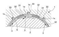
本参考例に係る軸受は、図1に概略正面図、図2に要部の中央横断面図をそれぞれ示すようなジャーナル軸受であり、軸2を取り付ける対象である軸受ハウジング1と軸2との間に設けられる。すなわち、前記軸受ハウジング1の内壁1aに設けられる。また、この軸受は、複数のフォイル3を具備するものであって、これら複数のフォイル3を軸2と前記軸受ハウジング1との間に配した際に、一のフォイル3と、他のフォイル3とが重なり合い、各フォイル3の一部が軸2に対向するアッパーフォイル31として機能するとともに、各フォイル3の他の一部が前記アッパーフォイル31と前記内壁1aとの間に位置し、内壁1aに対向するアンダーフォイル32として機能する。そして、前記フォイル3と前記軸2との間に図示しない気体膜を形成し、この気体膜の気圧を利用して軸2を支持する。すなわち、本参考例に係る軸受は、フォイル型のジャーナル気体軸受である。なお、前記図1及び図2では、フォイル3は形状の理解を容易にするため、一定の厚さで示されているが、実際には、例えば0.1〜0.2mmの板状であり、かつ軸2を巻回する環状に形成されている。
The bearing according to this reference example is a journal bearing having a schematic front view in FIG. 1 and a central cross-sectional view of the main part in FIG. 2, and includes a bearing
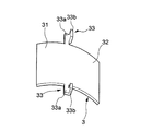
さらに詳述すると、前記フォイル3は、本参考例ではいずれも板状をなし、前記内壁1aに沿って配置される。また、このフォイル3の周方向中間部の軸方向端部には、該フォイル3を軸受ハウジング1に対して位置決めするための突起33を設けているとともに、この突起33を、前記フォイル3を形成する部材の軸方向端部を屈曲させることにより形成している。さらに詳述すると、この突起33は、図2に示すように、フォイル3の周方向中間部の軸方向両端部からそれぞれ軸方向に突出する接続部33aと、この接続部33aの端部を軸2から離間する方向に折り返して形成してなるとともに前記軸受ハウジング1に設けた凹部1xに挿入させてなる突出部33bとを有する。そして、本参考例では、各フォイル3の下流側ほぼ半分を、周方向に隣接するフォイル3の上流側ほぼ半分の軸2側に重ね合わせた状態で、前記突起33の突出部33bを軸受ハウジング1に設けた凹部1xに挿入することによりフォイル3を軸受ハウジング1に取り付けるようにしている。すなわち、前記図1及び図4に示すように、各フォイル3の下流側ほぼ半分が、軸2に対向するアッパーフォイル31として機能するとともに、各フォイル3の上流側ほぼ半分が、前記内壁1aと他方のフォイル3の前記アッパーフォイル31として機能する部分との間に位置するアンダーフォイル32として機能するようにしている。
More specifically, the
ここで、軸2が回転すると、軸2とフォイル3との隙間の空気等の気体が気体の粘性により引張られ、この隙間に形成してなる気体膜Sの圧力が上昇する。この圧力上昇によって、まず、各フォイル3のアッパーフォイル31として機能する部分が軸受ハウジング1側に向かう作用を受ける。この際、前記アッパーフォイル31として機能する部分は、隣接するフォイル3のアンダーフォイル32として機能する部分に圧接し、前記アンダーフォイル32として機能する部分が軸受ハウジング1側に向かう作用を受ける。そして、気体膜Sの形状が、例えば、入口部分から下流側に進むにつれ幅が小さくなるなど、適切な形状に維持され、前記アッパーフォイル31の下流側端縁近傍すなわち自由端近傍で気体の圧力上昇が生じる。この圧力上昇により軸受は軸2を非接触で支えることになる。
Here, when the
ここで、フォイル3に気体膜Sによる押さえつけ力が作用した際には、アンダーフォイル32は上流側に向かい移動する。一方、アッパーフォイル31は下流側に向かい移動する。すなわち、フォイル3に過大な押さえつけ力が作用した際には、これらアッパーフォイル31及びアンダーフォイル32は互いに逆方向に摺動し、この摺動の際に振動エネルギーを熱エネルギー等に変換して振動を抑制する効果であるダンピング効果が得られる。
Here, when the pressing force by the gas film S acts on the
以上に述べたように、本参考例に係る軸受の構成によれば、フォイル3の上流側を軸受ハウジング1の内壁1aに対向するアンダーフォイル32、下流側をこのアンダーフォイル32と軸2との間に位置するアッパーフォイル31とすることで、フォイル3に過大な押さえつけ力が作用した際にアンダーフォイル32とアッパーフォイル31とが逆方向に移動し、これらの間の相対的な摺動量を大きくしてより確実にダンピング効果を得られる構成の動圧気体軸受を、より少ない手間で実現することができる。
As described above, according to the configuration of the bearing according to the reference example , the upstream side of the
次いで、本発明の一実施形態を、図4を参照して説明する。なお、上述した参考例におけるものと共通の部位には、共通の名称及び符号を付している。以下、上述した参考例との相違点についてのみ述べる。 Then, an embodiment of the present invention will be described with reference to FIG. In addition, the common name and code | symbol are attached | subjected to the site | part common in the reference example mentioned above. Only differences from the above-described reference example will be described below.
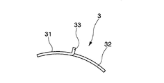
本実施形態においては、図4に示すように、突起33の突出部33bの突出端を折り返して折り返し部33xを設けるとともに、突出端すなわち折り返し部33xを前記軸受ハウジング1の凹部1xに当接させ、フォイル3が軸受ハウジング1に向けて押し付けられた際にこの折り返し部33xが弾性変形するようにしている。
In the present embodiment, as shown in FIG. 4, the protruding end of the
このように構成することにより、上述した参考例に係る構成の効果に加えて、以下のような作用効果が得られる。すなわち、フォイル3が軸受ハウジング1に大きな力で押し付けられ前記突起33の折り返し部33xが弾性変形した際に、アッパーフォイル31がさらに軸受ハウジング1に近接し、アンダーフォイル32とアッパーフォイル31とがさらに大きく相対移動するので、アンダーフォイル32とアッパーフォイル31との間の摩擦を利用したダンピング効果をより大きく得ることができるという効果が得られる。
By comprising in this way, in addition to the effect of the structure which concerns on the reference example mentioned above, the following effects are obtained. That is, when the
なお、本発明は以上に述べた実施形態に限らない。 The present invention is not limited to the embodiment described above.
例えば、軸受ハウジングの内壁に対向するアンダーフォイルとなるべき部位に、軸方向に延伸する突条を設ける等の手段により、アッパーフォイルとなるべき部位を軸に向かう方向に付勢するバネとしての機能を付与させてもよい。 For example, a function as a spring that urges the portion to be the upper foil in the direction toward the shaft by means such as providing a protrusion extending in the axial direction at the portion to be the underfoil facing the inner wall of the bearing housing. May be given.
また、ジャーナル軸受だけでなく、スラスト軸受に本発明を適用してもよい。 Moreover, you may apply this invention not only to a journal bearing but to a thrust bearing.
その他、本発明の趣旨を損ねない範囲で種々に変更してよい。 In addition, various changes may be made without departing from the spirit of the present invention.
1…軸受ハウジング
2…軸
3…フォイル
33…突起
DESCRIPTION OF
Claims (1)
前記突起の突出端に設けた折り返し部が軸受ハウジングに接触するとともに、前記フォイルが軸受ハウジングに向けて押し付けられた際に前記突起の折り返し部が弾性変形し、さらに、前記フォイルと前記軸受ハウジングとの間に、前記突起の折り返し部が弾性変形した際にフォイルが前記軸受ハウジングに近接することを許容するための隙間が設けられていることを特徴とする動圧気体軸受。 A projection having a bearing housing and a plurality of foils provided between the bearing housing and the shaft, and positioning the foil with respect to the bearing housing at an axial end of a circumferential middle portion of the foil And the protrusion is formed by bending the axial end portion of the member forming the foil, and the downstream portion of each foil is formed on the upstream side of the foil adjacent in the circumferential direction. A hydrodynamic gas bearing in which each foil is attached to the bearing housing in a state of being superimposed on the axial side of the part,
The folded portion provided at the projecting end of the projection contacts the bearing housing, and the folded portion of the projection is elastically deformed when the foil is pressed toward the bearing housing, and the foil, the bearing housing, Between these, a gap is provided for allowing the foil to approach the bearing housing when the folded portion of the protrusion is elastically deformed .
Priority Applications (1)
| Application Number | Priority Date | Filing Date | Title |
|---|---|---|---|
| JP2010004575A JP5333246B2 (en) | 2010-01-13 | 2010-01-13 | Dynamic pressure gas bearing |
Applications Claiming Priority (1)
| Application Number | Priority Date | Filing Date | Title |
|---|---|---|---|
| JP2010004575A JP5333246B2 (en) | 2010-01-13 | 2010-01-13 | Dynamic pressure gas bearing |
Publications (2)
| Publication Number | Publication Date |
|---|---|
| JP2011144846A JP2011144846A (en) | 2011-07-28 |
| JP5333246B2 true JP5333246B2 (en) | 2013-11-06 |
Family
ID=44459881
Family Applications (1)
| Application Number | Title | Priority Date | Filing Date |
|---|---|---|---|
| JP2010004575A Expired - Fee Related JP5333246B2 (en) | 2010-01-13 | 2010-01-13 | Dynamic pressure gas bearing |
Country Status (1)
| Country | Link |
|---|---|
| JP (1) | JP5333246B2 (en) |
Families Citing this family (14)
| Publication number | Priority date | Publication date | Assignee | Title |
|---|---|---|---|---|
| JP5765122B2 (en) * | 2011-08-01 | 2015-08-19 | 株式会社Ihi | Radial foil bearing |
| JP5862186B2 (en) * | 2011-10-13 | 2016-02-16 | 株式会社Ihi | Radial foil bearing |
| JP5817449B2 (en) | 2011-11-09 | 2015-11-18 | 株式会社Ihi | Radial foil bearing |
| JP6136135B2 (en) * | 2012-07-18 | 2017-05-31 | 株式会社Ihi | Radial foil bearing |
| JP5929626B2 (en) | 2012-08-14 | 2016-06-08 | 株式会社Ihi | Radial foil bearing |
| CN104884825B (en) | 2012-12-19 | 2018-02-09 | Ntn株式会社 | Thin Pad Bearings and Turbomachinery |
| JP6144222B2 (en) * | 2014-03-25 | 2017-06-07 | Ntn株式会社 | Foil bearing |
| RU2658260C2 (en) * | 2015-02-04 | 2018-06-19 | Сергей Иванович Сигачев | Radial flap gas dynamic bearing |
| WO2017169676A1 (en) * | 2016-03-30 | 2017-10-05 | Ntn株式会社 | Foil bearing |
| JP2019019914A (en) * | 2017-07-19 | 2019-02-07 | Ntn株式会社 | Foil bearing |
| JP6965797B2 (en) * | 2018-03-07 | 2021-11-10 | 株式会社Ihi | Radial foil bearing |
| CN113710908B (en) * | 2019-04-04 | 2023-07-21 | 株式会社Ihi | Radial Foil Bearings |
| DE112021004989T5 (en) * | 2020-11-17 | 2023-07-06 | Ihi Corporation | axial air bearing |
| CN116498646B (en) * | 2022-09-06 | 2025-07-11 | 哈尔滨工业大学(深圳) | A gas dynamic pressure bearing with fin-type support foil |
Family Cites Families (3)
| Publication number | Priority date | Publication date | Assignee | Title |
|---|---|---|---|---|
| US4178046A (en) * | 1976-05-24 | 1979-12-11 | The Garrett Corporation | Foil bearing |
| JPS60175914U (en) * | 1984-04-30 | 1985-11-21 | 株式会社島津製作所 | oil bearing |
| JP4935702B2 (en) * | 2008-02-05 | 2012-05-23 | 株式会社島津製作所 | Dynamic pressure gas bearing mounting structure |
-
2010
- 2010-01-13 JP JP2010004575A patent/JP5333246B2/en not_active Expired - Fee Related
Also Published As
| Publication number | Publication date |
|---|---|
| JP2011144846A (en) | 2011-07-28 |
Similar Documents
| Publication | Publication Date | Title |
|---|---|---|
| JP5333246B2 (en) | Dynamic pressure gas bearing | |
| JP4935702B2 (en) | Dynamic pressure gas bearing mounting structure | |
| JP5321332B2 (en) | Dynamic pressure gas bearing | |
| JP5531994B2 (en) | Dynamic pressure gas bearing | |
| JP4973590B2 (en) | Dynamic pressure gas bearing | |
| KR20110009219A (en) | Foil bearing | |
| WO2015087675A1 (en) | Foil bearing, and foil bearing unit and turbo machine each having same | |
| JP2002061645A (en) | Dynamic pressure type air bearing | |
| JP6479456B2 (en) | Foil, foil bearing, and method of assembling foil bearing | |
| JP2011017385A (en) | Dynamic pressure gas bearing | |
| JP2016223426A (en) | Flexible packing ring for turbine | |
| KR101513104B1 (en) | Air foil bearing having divided structure | |
| JP5472170B2 (en) | Dynamic pressure gas bearing | |
| JP5257370B2 (en) | Dynamic pressure gas bearing | |
| WO2018016268A1 (en) | Foil bearing | |
| JP5757095B2 (en) | Dynamic pressure gas bearing | |
| JP2017180685A (en) | Foil bearing | |
| JP6305749B2 (en) | Foil bearing, foil bearing unit having the same, and turbomachine | |
| JP5644547B2 (en) | Dynamic pressure gas bearing | |
| WO2019017134A1 (en) | Foil bearing | |
| JP6651397B2 (en) | Foil bearing | |
| JP5531995B2 (en) | Dynamic pressure gas bearing | |
| US20100278464A1 (en) | Blade Gasodynamic Bearing | |
| US9732790B2 (en) | Aerodynamic foil bearing | |
| JP2009174594A (en) | Dynamic pressure gas bearing |
Legal Events
| Date | Code | Title | Description |
|---|---|---|---|
| A621 | Written request for application examination |
Free format text: JAPANESE INTERMEDIATE CODE: A621 Effective date: 20120416 |
|
| A131 | Notification of reasons for refusal |
Free format text: JAPANESE INTERMEDIATE CODE: A131 Effective date: 20130319 |
|
| A977 | Report on retrieval |
Free format text: JAPANESE INTERMEDIATE CODE: A971007 Effective date: 20130322 |
|
| A521 | Written amendment |
Free format text: JAPANESE INTERMEDIATE CODE: A523 Effective date: 20130517 |
|
| TRDD | Decision of grant or rejection written | ||
| A01 | Written decision to grant a patent or to grant a registration (utility model) |
Free format text: JAPANESE INTERMEDIATE CODE: A01 Effective date: 20130702 |
|
| A61 | First payment of annual fees (during grant procedure) |
Free format text: JAPANESE INTERMEDIATE CODE: A61 Effective date: 20130715 |
|
| R151 | Written notification of patent or utility model registration |
Ref document number: 5333246 Country of ref document: JP Free format text: JAPANESE INTERMEDIATE CODE: R151 |
|
| LAPS | Cancellation because of no payment of annual fees |