JP5342000B2 - Slewing drive - Google Patents
Slewing drive Download PDFInfo
- Publication number
- JP5342000B2 JP5342000B2 JP2011524656A JP2011524656A JP5342000B2 JP 5342000 B2 JP5342000 B2 JP 5342000B2 JP 2011524656 A JP2011524656 A JP 2011524656A JP 2011524656 A JP2011524656 A JP 2011524656A JP 5342000 B2 JP5342000 B2 JP 5342000B2
- Authority
- JP
- Japan
- Prior art keywords
- gear
- turning
- outer ring
- drive device
- pinion
- Prior art date
- Legal status (The legal status is an assumption and is not a legal conclusion. Google has not performed a legal analysis and makes no representation as to the accuracy of the status listed.)
- Active
Links
Images


Classifications
-
- E—FIXED CONSTRUCTIONS
- E02—HYDRAULIC ENGINEERING; FOUNDATIONS; SOIL SHIFTING
- E02F—DREDGING; SOIL-SHIFTING
- E02F9/00—Component parts of dredgers or soil-shifting machines, not restricted to one of the kinds covered by groups E02F3/00 - E02F7/00
- E02F9/08—Superstructures; Supports for superstructures
- E02F9/10—Supports for movable superstructures mounted on travelling or walking gears or on other superstructures
- E02F9/12—Slewing or traversing gears
- E02F9/121—Turntables, i.e. structure rotatable about 360°
- E02F9/123—Drives or control devices specially adapted therefor
-
- B—PERFORMING OPERATIONS; TRANSPORTING
- B60—VEHICLES IN GENERAL
- B60L—PROPULSION OF ELECTRICALLY-PROPELLED VEHICLES; SUPPLYING ELECTRIC POWER FOR AUXILIARY EQUIPMENT OF ELECTRICALLY-PROPELLED VEHICLES; ELECTRODYNAMIC BRAKE SYSTEMS FOR VEHICLES IN GENERAL; MAGNETIC SUSPENSION OR LEVITATION FOR VEHICLES; MONITORING OPERATING VARIABLES OF ELECTRICALLY-PROPELLED VEHICLES; ELECTRIC SAFETY DEVICES FOR ELECTRICALLY-PROPELLED VEHICLES
- B60L1/00—Supplying electric power to auxiliary equipment of vehicles
- B60L1/003—Supplying electric power to auxiliary equipment of vehicles to auxiliary motors, e.g. for pumps, compressors
-
- B—PERFORMING OPERATIONS; TRANSPORTING
- B60—VEHICLES IN GENERAL
- B60L—PROPULSION OF ELECTRICALLY-PROPELLED VEHICLES; SUPPLYING ELECTRIC POWER FOR AUXILIARY EQUIPMENT OF ELECTRICALLY-PROPELLED VEHICLES; ELECTRODYNAMIC BRAKE SYSTEMS FOR VEHICLES IN GENERAL; MAGNETIC SUSPENSION OR LEVITATION FOR VEHICLES; MONITORING OPERATING VARIABLES OF ELECTRICALLY-PROPELLED VEHICLES; ELECTRIC SAFETY DEVICES FOR ELECTRICALLY-PROPELLED VEHICLES
- B60L1/00—Supplying electric power to auxiliary equipment of vehicles
- B60L1/20—Energy regeneration from auxiliary equipment
-
- B—PERFORMING OPERATIONS; TRANSPORTING
- B60—VEHICLES IN GENERAL
- B60L—PROPULSION OF ELECTRICALLY-PROPELLED VEHICLES; SUPPLYING ELECTRIC POWER FOR AUXILIARY EQUIPMENT OF ELECTRICALLY-PROPELLED VEHICLES; ELECTRODYNAMIC BRAKE SYSTEMS FOR VEHICLES IN GENERAL; MAGNETIC SUSPENSION OR LEVITATION FOR VEHICLES; MONITORING OPERATING VARIABLES OF ELECTRICALLY-PROPELLED VEHICLES; ELECTRIC SAFETY DEVICES FOR ELECTRICALLY-PROPELLED VEHICLES
- B60L15/00—Methods, circuits, or devices for controlling the traction-motor speed of electrically-propelled vehicles
- B60L15/20—Methods, circuits, or devices for controlling the traction-motor speed of electrically-propelled vehicles for control of the vehicle or its driving motor to achieve a desired performance, e.g. speed, torque, programmed variation of speed
- B60L15/2009—Methods, circuits, or devices for controlling the traction-motor speed of electrically-propelled vehicles for control of the vehicle or its driving motor to achieve a desired performance, e.g. speed, torque, programmed variation of speed for braking
-
- B—PERFORMING OPERATIONS; TRANSPORTING
- B60—VEHICLES IN GENERAL
- B60L—PROPULSION OF ELECTRICALLY-PROPELLED VEHICLES; SUPPLYING ELECTRIC POWER FOR AUXILIARY EQUIPMENT OF ELECTRICALLY-PROPELLED VEHICLES; ELECTRODYNAMIC BRAKE SYSTEMS FOR VEHICLES IN GENERAL; MAGNETIC SUSPENSION OR LEVITATION FOR VEHICLES; MONITORING OPERATING VARIABLES OF ELECTRICALLY-PROPELLED VEHICLES; ELECTRIC SAFETY DEVICES FOR ELECTRICALLY-PROPELLED VEHICLES
- B60L53/00—Methods of charging batteries, specially adapted for electric vehicles; Charging stations or on-board charging equipment therefor; Exchange of energy storage elements in electric vehicles
- B60L53/10—Methods of charging batteries, specially adapted for electric vehicles; Charging stations or on-board charging equipment therefor; Exchange of energy storage elements in electric vehicles characterised by the energy transfer between the charging station and the vehicle
- B60L53/14—Conductive energy transfer
-
- B—PERFORMING OPERATIONS; TRANSPORTING
- B60—VEHICLES IN GENERAL
- B60L—PROPULSION OF ELECTRICALLY-PROPELLED VEHICLES; SUPPLYING ELECTRIC POWER FOR AUXILIARY EQUIPMENT OF ELECTRICALLY-PROPELLED VEHICLES; ELECTRODYNAMIC BRAKE SYSTEMS FOR VEHICLES IN GENERAL; MAGNETIC SUSPENSION OR LEVITATION FOR VEHICLES; MONITORING OPERATING VARIABLES OF ELECTRICALLY-PROPELLED VEHICLES; ELECTRIC SAFETY DEVICES FOR ELECTRICALLY-PROPELLED VEHICLES
- B60L7/00—Electrodynamic brake systems for vehicles in general
- B60L7/10—Dynamic electric regenerative braking
- B60L7/14—Dynamic electric regenerative braking for vehicles propelled by AC motors
-
- E—FIXED CONSTRUCTIONS
- E02—HYDRAULIC ENGINEERING; FOUNDATIONS; SOIL SHIFTING
- E02F—DREDGING; SOIL-SHIFTING
- E02F9/00—Component parts of dredgers or soil-shifting machines, not restricted to one of the kinds covered by groups E02F3/00 - E02F7/00
- E02F9/20—Drives; Control devices
- E02F9/2058—Electric or electro-mechanical or mechanical control devices of vehicle sub-units
- E02F9/2062—Control of propulsion units
- E02F9/207—Control of propulsion units of the type electric propulsion units, e.g. electric motors or generators
-
- E—FIXED CONSTRUCTIONS
- E02—HYDRAULIC ENGINEERING; FOUNDATIONS; SOIL SHIFTING
- E02F—DREDGING; SOIL-SHIFTING
- E02F9/00—Component parts of dredgers or soil-shifting machines, not restricted to one of the kinds covered by groups E02F3/00 - E02F7/00
- E02F9/20—Drives; Control devices
- E02F9/22—Hydraulic or pneumatic drives
- E02F9/2217—Hydraulic or pneumatic drives with energy recovery arrangements, e.g. using accumulators, flywheels
-
- H—ELECTRICITY
- H02—GENERATION; CONVERSION OR DISTRIBUTION OF ELECTRIC POWER
- H02K—DYNAMO-ELECTRIC MACHINES
- H02K16/00—Machines with more than one rotor or stator
-
- H—ELECTRICITY
- H02—GENERATION; CONVERSION OR DISTRIBUTION OF ELECTRIC POWER
- H02K—DYNAMO-ELECTRIC MACHINES
- H02K7/00—Arrangements for handling mechanical energy structurally associated with dynamo-electric machines, e.g. structural association with mechanical driving motors or auxiliary dynamo-electric machines
- H02K7/10—Structural association with clutches, brakes, gears, pulleys or mechanical starters
- H02K7/116—Structural association with clutches, brakes, gears, pulleys or mechanical starters with gears
-
- B—PERFORMING OPERATIONS; TRANSPORTING
- B60—VEHICLES IN GENERAL
- B60L—PROPULSION OF ELECTRICALLY-PROPELLED VEHICLES; SUPPLYING ELECTRIC POWER FOR AUXILIARY EQUIPMENT OF ELECTRICALLY-PROPELLED VEHICLES; ELECTRODYNAMIC BRAKE SYSTEMS FOR VEHICLES IN GENERAL; MAGNETIC SUSPENSION OR LEVITATION FOR VEHICLES; MONITORING OPERATING VARIABLES OF ELECTRICALLY-PROPELLED VEHICLES; ELECTRIC SAFETY DEVICES FOR ELECTRICALLY-PROPELLED VEHICLES
- B60L2200/00—Type of vehicles
- B60L2200/40—Working vehicles
-
- B—PERFORMING OPERATIONS; TRANSPORTING
- B60—VEHICLES IN GENERAL
- B60L—PROPULSION OF ELECTRICALLY-PROPELLED VEHICLES; SUPPLYING ELECTRIC POWER FOR AUXILIARY EQUIPMENT OF ELECTRICALLY-PROPELLED VEHICLES; ELECTRODYNAMIC BRAKE SYSTEMS FOR VEHICLES IN GENERAL; MAGNETIC SUSPENSION OR LEVITATION FOR VEHICLES; MONITORING OPERATING VARIABLES OF ELECTRICALLY-PROPELLED VEHICLES; ELECTRIC SAFETY DEVICES FOR ELECTRICALLY-PROPELLED VEHICLES
- B60L2210/00—Converter types
- B60L2210/30—AC to DC converters
-
- B—PERFORMING OPERATIONS; TRANSPORTING
- B60—VEHICLES IN GENERAL
- B60L—PROPULSION OF ELECTRICALLY-PROPELLED VEHICLES; SUPPLYING ELECTRIC POWER FOR AUXILIARY EQUIPMENT OF ELECTRICALLY-PROPELLED VEHICLES; ELECTRODYNAMIC BRAKE SYSTEMS FOR VEHICLES IN GENERAL; MAGNETIC SUSPENSION OR LEVITATION FOR VEHICLES; MONITORING OPERATING VARIABLES OF ELECTRICALLY-PROPELLED VEHICLES; ELECTRIC SAFETY DEVICES FOR ELECTRICALLY-PROPELLED VEHICLES
- B60L2220/00—Electrical machine types; Structures or applications thereof
- B60L2220/10—Electrical machine types
- B60L2220/14—Synchronous machines
-
- B—PERFORMING OPERATIONS; TRANSPORTING
- B60—VEHICLES IN GENERAL
- B60L—PROPULSION OF ELECTRICALLY-PROPELLED VEHICLES; SUPPLYING ELECTRIC POWER FOR AUXILIARY EQUIPMENT OF ELECTRICALLY-PROPELLED VEHICLES; ELECTRODYNAMIC BRAKE SYSTEMS FOR VEHICLES IN GENERAL; MAGNETIC SUSPENSION OR LEVITATION FOR VEHICLES; MONITORING OPERATING VARIABLES OF ELECTRICALLY-PROPELLED VEHICLES; ELECTRIC SAFETY DEVICES FOR ELECTRICALLY-PROPELLED VEHICLES
- B60L2240/00—Control parameters of input or output; Target parameters
- B60L2240/10—Vehicle control parameters
- B60L2240/12—Speed
-
- B—PERFORMING OPERATIONS; TRANSPORTING
- B60—VEHICLES IN GENERAL
- B60L—PROPULSION OF ELECTRICALLY-PROPELLED VEHICLES; SUPPLYING ELECTRIC POWER FOR AUXILIARY EQUIPMENT OF ELECTRICALLY-PROPELLED VEHICLES; ELECTRODYNAMIC BRAKE SYSTEMS FOR VEHICLES IN GENERAL; MAGNETIC SUSPENSION OR LEVITATION FOR VEHICLES; MONITORING OPERATING VARIABLES OF ELECTRICALLY-PROPELLED VEHICLES; ELECTRIC SAFETY DEVICES FOR ELECTRICALLY-PROPELLED VEHICLES
- B60L2240/00—Control parameters of input or output; Target parameters
- B60L2240/40—Drive Train control parameters
- B60L2240/42—Drive Train control parameters related to electric machines
- B60L2240/421—Speed
-
- B—PERFORMING OPERATIONS; TRANSPORTING
- B60—VEHICLES IN GENERAL
- B60L—PROPULSION OF ELECTRICALLY-PROPELLED VEHICLES; SUPPLYING ELECTRIC POWER FOR AUXILIARY EQUIPMENT OF ELECTRICALLY-PROPELLED VEHICLES; ELECTRODYNAMIC BRAKE SYSTEMS FOR VEHICLES IN GENERAL; MAGNETIC SUSPENSION OR LEVITATION FOR VEHICLES; MONITORING OPERATING VARIABLES OF ELECTRICALLY-PROPELLED VEHICLES; ELECTRIC SAFETY DEVICES FOR ELECTRICALLY-PROPELLED VEHICLES
- B60L2240/00—Control parameters of input or output; Target parameters
- B60L2240/40—Drive Train control parameters
- B60L2240/42—Drive Train control parameters related to electric machines
- B60L2240/423—Torque
-
- B—PERFORMING OPERATIONS; TRANSPORTING
- B60—VEHICLES IN GENERAL
- B60L—PROPULSION OF ELECTRICALLY-PROPELLED VEHICLES; SUPPLYING ELECTRIC POWER FOR AUXILIARY EQUIPMENT OF ELECTRICALLY-PROPELLED VEHICLES; ELECTRODYNAMIC BRAKE SYSTEMS FOR VEHICLES IN GENERAL; MAGNETIC SUSPENSION OR LEVITATION FOR VEHICLES; MONITORING OPERATING VARIABLES OF ELECTRICALLY-PROPELLED VEHICLES; ELECTRIC SAFETY DEVICES FOR ELECTRICALLY-PROPELLED VEHICLES
- B60L2240/00—Control parameters of input or output; Target parameters
- B60L2240/40—Drive Train control parameters
- B60L2240/48—Drive Train control parameters related to transmissions
- B60L2240/486—Operating parameters
-
- B—PERFORMING OPERATIONS; TRANSPORTING
- B60—VEHICLES IN GENERAL
- B60L—PROPULSION OF ELECTRICALLY-PROPELLED VEHICLES; SUPPLYING ELECTRIC POWER FOR AUXILIARY EQUIPMENT OF ELECTRICALLY-PROPELLED VEHICLES; ELECTRODYNAMIC BRAKE SYSTEMS FOR VEHICLES IN GENERAL; MAGNETIC SUSPENSION OR LEVITATION FOR VEHICLES; MONITORING OPERATING VARIABLES OF ELECTRICALLY-PROPELLED VEHICLES; ELECTRIC SAFETY DEVICES FOR ELECTRICALLY-PROPELLED VEHICLES
- B60L2250/00—Driver interactions
- B60L2250/24—Driver interactions by lever actuation
-
- Y—GENERAL TAGGING OF NEW TECHNOLOGICAL DEVELOPMENTS; GENERAL TAGGING OF CROSS-SECTIONAL TECHNOLOGIES SPANNING OVER SEVERAL SECTIONS OF THE IPC; TECHNICAL SUBJECTS COVERED BY FORMER USPC CROSS-REFERENCE ART COLLECTIONS [XRACs] AND DIGESTS
- Y02—TECHNOLOGIES OR APPLICATIONS FOR MITIGATION OR ADAPTATION AGAINST CLIMATE CHANGE
- Y02T—CLIMATE CHANGE MITIGATION TECHNOLOGIES RELATED TO TRANSPORTATION
- Y02T10/00—Road transport of goods or passengers
- Y02T10/60—Other road transportation technologies with climate change mitigation effect
- Y02T10/64—Electric machine technologies in electromobility
-
- Y—GENERAL TAGGING OF NEW TECHNOLOGICAL DEVELOPMENTS; GENERAL TAGGING OF CROSS-SECTIONAL TECHNOLOGIES SPANNING OVER SEVERAL SECTIONS OF THE IPC; TECHNICAL SUBJECTS COVERED BY FORMER USPC CROSS-REFERENCE ART COLLECTIONS [XRACs] AND DIGESTS
- Y02—TECHNOLOGIES OR APPLICATIONS FOR MITIGATION OR ADAPTATION AGAINST CLIMATE CHANGE
- Y02T—CLIMATE CHANGE MITIGATION TECHNOLOGIES RELATED TO TRANSPORTATION
- Y02T10/00—Road transport of goods or passengers
- Y02T10/60—Other road transportation technologies with climate change mitigation effect
- Y02T10/70—Energy storage systems for electromobility, e.g. batteries
-
- Y—GENERAL TAGGING OF NEW TECHNOLOGICAL DEVELOPMENTS; GENERAL TAGGING OF CROSS-SECTIONAL TECHNOLOGIES SPANNING OVER SEVERAL SECTIONS OF THE IPC; TECHNICAL SUBJECTS COVERED BY FORMER USPC CROSS-REFERENCE ART COLLECTIONS [XRACs] AND DIGESTS
- Y02—TECHNOLOGIES OR APPLICATIONS FOR MITIGATION OR ADAPTATION AGAINST CLIMATE CHANGE
- Y02T—CLIMATE CHANGE MITIGATION TECHNOLOGIES RELATED TO TRANSPORTATION
- Y02T10/00—Road transport of goods or passengers
- Y02T10/60—Other road transportation technologies with climate change mitigation effect
- Y02T10/7072—Electromobility specific charging systems or methods for batteries, ultracapacitors, supercapacitors or double-layer capacitors
-
- Y—GENERAL TAGGING OF NEW TECHNOLOGICAL DEVELOPMENTS; GENERAL TAGGING OF CROSS-SECTIONAL TECHNOLOGIES SPANNING OVER SEVERAL SECTIONS OF THE IPC; TECHNICAL SUBJECTS COVERED BY FORMER USPC CROSS-REFERENCE ART COLLECTIONS [XRACs] AND DIGESTS
- Y02—TECHNOLOGIES OR APPLICATIONS FOR MITIGATION OR ADAPTATION AGAINST CLIMATE CHANGE
- Y02T—CLIMATE CHANGE MITIGATION TECHNOLOGIES RELATED TO TRANSPORTATION
- Y02T10/00—Road transport of goods or passengers
- Y02T10/60—Other road transportation technologies with climate change mitigation effect
- Y02T10/72—Electric energy management in electromobility
-
- Y—GENERAL TAGGING OF NEW TECHNOLOGICAL DEVELOPMENTS; GENERAL TAGGING OF CROSS-SECTIONAL TECHNOLOGIES SPANNING OVER SEVERAL SECTIONS OF THE IPC; TECHNICAL SUBJECTS COVERED BY FORMER USPC CROSS-REFERENCE ART COLLECTIONS [XRACs] AND DIGESTS
- Y02—TECHNOLOGIES OR APPLICATIONS FOR MITIGATION OR ADAPTATION AGAINST CLIMATE CHANGE
- Y02T—CLIMATE CHANGE MITIGATION TECHNOLOGIES RELATED TO TRANSPORTATION
- Y02T90/00—Enabling technologies or technologies with a potential or indirect contribution to GHG emissions mitigation
- Y02T90/10—Technologies relating to charging of electric vehicles
- Y02T90/14—Plug-in electric vehicles
Landscapes
- Engineering & Computer Science (AREA)
- Power Engineering (AREA)
- Transportation (AREA)
- Mechanical Engineering (AREA)
- Mining & Mineral Resources (AREA)
- Civil Engineering (AREA)
- General Engineering & Computer Science (AREA)
- Structural Engineering (AREA)
- Operation Control Of Excavators (AREA)
- Component Parts Of Construction Machinery (AREA)
- Hybrid Electric Vehicles (AREA)
Description
本発明は、走行体の上に旋回体を旋回動自在に支持するとともに旋回体を旋回動させる旋回駆動装置、特に建設機械用に適した旋回駆動装置に関する。 The present invention relates to a turning drive device that supports a turning body on a traveling body so as to be capable of turning, and to turn the turning body, and particularly relates to a turning drive device suitable for a construction machine.
従来、油圧ショベル等の建設機械では、エンジンにより駆動される油圧ポンプと、油圧ポンプからの圧油により駆動される油圧モータとを備え、油圧モータの駆動により走行体に対して旋回体を旋回動させるように構成した旋回駆動装置が広く用いられている。しかしながら、油圧アクチュエータ(油圧ポンプ、油圧モータ)は、電気アクチュエータに比べてエネルギー効率が悪い(エネルギー損失が大きい)。そこで、電動モータを油圧モータと同軸に連結して設け、建設機械における動作や目的に応じて油圧モータと電動モータを併用する旋回駆動装置が提案されている(例えば、特許文献1、特許文献2を参照)。また、旋回停止時における旋回体の慣性力を利用して発電する(エネルギー回生を行う)発電機を備えた旋回駆動装置も提案されている(例えば、特許文献3を参照)。 2. Description of the Related Art Conventionally, a construction machine such as a hydraulic excavator is provided with a hydraulic pump driven by an engine and a hydraulic motor driven by pressure oil from the hydraulic pump. A swivel drive device configured so as to be used is widely used. However, hydraulic actuators (hydraulic pumps, hydraulic motors) are less energy efficient (high energy loss) than electrical actuators. In view of this, there has been proposed a swivel drive device in which an electric motor is provided coaxially with a hydraulic motor and uses both the hydraulic motor and the electric motor in accordance with the operation and purpose of the construction machine (for example, Patent Document 1 and Patent Document 2). See). There has also been proposed a turning drive device including a generator that generates electric power using the inertial force of the turning body at the time of turning stop (performs energy regeneration) (see, for example, Patent Document 3).
ところで、上記のように油圧モータと電動モータを同軸に連結すると、この連結モータ自体のサイズが単体のモータと比較して大きくなり、設置スペースの限られた小型の建設機械に搭載するには適さないという問題があった。また、小型の建設機械では、大容量のバッテリを搭載することが困難であるため、バッテリの電力を有効に利用することができる旋回駆動装置が求められる。さらに、小型の建設機械では、旋回停止時における旋回体の慣性力が比較的小さいため、この小さな旋回体の慣性力でも多くのエネルギー回生を行うことができる旋回駆動装置が求められる。 By the way, when the hydraulic motor and the electric motor are connected coaxially as described above, the size of the connecting motor itself is larger than that of a single motor, and it is suitable for mounting on a small construction machine having a limited installation space. There was no problem. Further, since it is difficult to mount a large capacity battery in a small construction machine, a turning drive device that can effectively use the power of the battery is required. Furthermore, in a small construction machine, since the inertial force of the revolving structure when the revolving is stopped is relatively small, there is a demand for a revolving drive device that can perform a large amount of energy regeneration with the inertial force of this small revolving structure.
本発明はこのような課題に鑑みてなされたものであり、旋回油圧モータと旋回電動モータのトルク配分を最適化してバッテリの電力を有効に利用することができ、小型の建設機械にも適用することができる旋回駆動装置を提供することを目的とする。 The present invention has been made in view of such a problem, and can optimize the torque distribution between the swing hydraulic motor and the swing electric motor to effectively use the power of the battery, and is also applied to a small construction machine. An object of the present invention is to provide a swivel drive device that can perform the above operation.
上記目的を達成するため、本発明に係る旋回駆動装置(例えば、実施形態における旋回駆動装置60)は、走行体(例えば、実施形態における走行装置10)の上に旋回体(例えば、実施形態における車両本体20)を旋回動自在に支持するとともに前記旋回体を旋回動させる装置であって、前記走行体に対して前記旋回体を旋回動自在に支持する旋回ベアリングと、前記走行体および前記旋回体のいずれか一方の側に、前記旋回ベアリングと同軸上に位置して設けられた第1旋回ギヤ部材と、前記走行体および前記旋回体における前記第1旋回ギヤ部材が設けられた側もしくは他方の側に、前記旋回ベアリングと同軸上に位置して設けられた第2旋回ギヤ部材と、前記第1旋回ギヤ部材のギヤ部と噛合する第1ピニオンギヤを有し、油圧力を用いて前記第1ピニオンギヤを回転駆動して前記第1旋回ギヤ部材を回転駆動可能な油圧モータと、前記第2旋回ギヤ部材と噛合する第2ピニオンギヤを有し、電力を用いて前記第2ピニオンギヤを回転駆動して前記第2旋回ギヤ部材を回転駆動可能であり、且つ前記第2旋回ギヤ部材の回転による前記第2ピニオンギヤの回転駆動により回生発電が可能な回生電動モータとを備え、前記第1ピニオンギヤにより前記第1旋回ギヤ部材へ回転伝達を行う第1減速比が、前記第2ピニオンギヤにより前記第2旋回ギヤ部材へ回転伝達を行う第2減速比と相違するように構成される。
In order to achieve the above object, a turning drive device (for example, the
上記構成において、好ましくは、前記第1減速比が前記第2減速比より小さい。なお、前記第1ピニオンギヤから前記第1旋回ギヤ部材への回転伝達および前記第2ピニオンギヤから前記第2旋回ギヤ部材への回転伝達の少なくともいずれか一方が変速ギヤ列を介して行われるように構成しても良い。 In the above configuration, the first reduction ratio is preferably smaller than the second reduction ratio. Note that at least one of rotation transmission from the first pinion gear to the first turning gear member and rotation transmission from the second pinion gear to the second turning gear member is performed via a transmission gear train. You may do it.
上記構成の本発明に係る旋回駆動装置において、好ましくは、前記旋回ベアリングが前記走行体および前記旋回体のいずれか一方に取り付けられる外輪と、前記外輪の内径側に転動体を介して相対回転自在に設けられて前記走行体および前記旋回体の他方に取り付けられる内輪とを有して構成され、前記第1旋回ギヤ部材が前記内輪に一体結合して設けられた第1ギヤを有して構成され、前記第2旋回ギヤ部材が前記内輪に一体結合して設けられるとともに前記第1ギヤと歯数の異なる第2ギヤを有して構成され、前記油圧モータは前記外輪が設けられる側に設けられ、前記第1ピニオンギヤが前記第1ギヤと噛合し、前記回生電動モータは前記外輪が設けられる側に設けられ、前記第2ピニオンギヤが前記第2ギヤと噛合するように構成される。 In the turning drive device according to the present invention having the above-described configuration, preferably, the turning bearing is relatively rotatable via a rolling element on an inner diameter side of the outer ring, the outer ring being attached to one of the traveling body and the turning body. And an inner ring that is attached to the other of the traveling body and the revolving structure, and the first revolving gear member has a first gear that is integrally coupled to the inner ring. The second turning gear member is provided integrally with the inner ring and has a second gear having a different number of teeth from the first gear, and the hydraulic motor is provided on the side where the outer ring is provided. The first pinion gear meshes with the first gear, the regenerative electric motor is provided on the side where the outer ring is provided, and the second pinion gear meshes with the second gear. That.
この場合において、好ましくは、前記第1ギヤおよび第2ギヤのいずれか一方が前記内輪の内周面に形成された内歯ギヤから構成され、前記第1ギヤおよび第2ギヤの他方が前記内輪に一体結合されたリング状部材の内周面に形成された内歯ギヤから構成される。 In this case, preferably, one of the first gear and the second gear is configured by an internal gear formed on an inner peripheral surface of the inner ring, and the other of the first gear and the second gear is the inner ring. It is comprised from the internal gear formed in the internal peripheral surface of the ring-shaped member integrally couple | bonded with.
さらに好ましくは、前記第1旋回ギヤ部材および前記第2旋回ギヤ部材が同一の歯数を有して一体に形成され、前記第1ピニオンギヤおよび前記第2ピニオンギヤの歯数を相違させることにより前記第1および前記第2減速比を相違させるように構成される。なお、この場合に、前記第1旋回ギヤ部材および前記第2旋回ギヤ部材が前記内輪の内周面に形成された内歯ギヤから構成されても良い。 More preferably, the first turning gear member and the second turning gear member are integrally formed with the same number of teeth, and the first pinion gear and the second pinion gear have different numbers of teeth. 1 and the second reduction ratio are configured to be different. In this case, the first turning gear member and the second turning gear member may be constituted by internal gears formed on the inner peripheral surface of the inner ring.
上記構成の本発明に係る旋回駆動装置において、好ましくは、前記旋回ベアリングが前記走行体および前記旋回体のいずれか一方に取り付けられる外輪と、前記外輪の内径側に転動体を介して相対回転自在に設けられて前記走行体および前記旋回体の他方に取り付けられる内輪とを有して構成され、前記第1旋回ギヤ部材が前記内輪に一体結合して設けられた第1ギヤを有して構成され、前記第2旋回ギヤ部材が前記外輪に一体結合して設けられるとともに前記第1ギヤと歯数の異なる第2ギヤを有して構成され、前記油圧モータは前記外輪が設けられる側に設けられ、前記第1ピニオンギヤが前記第1ギヤと噛合し、前記回生電動モータは前記内輪が設けられる側に設けられ、前記第2ピニオンギヤが前記第2ギヤと噛合するよう構成される。 In the turning drive device according to the present invention having the above-described configuration, preferably, the turning bearing is relatively rotatable via a rolling element on an inner diameter side of the outer ring, the outer ring being attached to one of the traveling body and the turning body. And an inner ring that is attached to the other of the traveling body and the revolving structure, and the first revolving gear member has a first gear that is integrally coupled to the inner ring. The second turning gear member is provided integrally with the outer ring and has a second gear having a different number of teeth from the first gear, and the hydraulic motor is provided on the side where the outer ring is provided. The first pinion gear meshes with the first gear, the regenerative electric motor is provided on the side where the inner ring is provided, and the second pinion gear meshes with the second gear. .
この場合において、好ましくは、前記第1ギヤが前記内輪の内周面に形成された内歯ギヤから構成され、前記第2ギヤが前記外輪の外周面に形成された外歯ギヤから構成される。 In this case, preferably, the first gear is composed of an internal gear formed on the inner peripheral surface of the inner ring, and the second gear is composed of an external gear formed on the outer peripheral surface of the outer ring. .
上記構成の本発明に係る旋回駆動装置において、好ましくは、前記旋回ベアリングが前記走行体および前記旋回体のいずれか一方に取り付けられる外輪と、前記外輪の内径側に転動体を介して相対回転自在に設けられて前記走行体および前記旋回体の他方に取り付けられる内輪とを有して構成され、前記第1旋回ギヤ部材が前記外輪に一体結合して設けられた第1ギヤを有して構成され、前記第2旋回ギヤ部材が前記内輪に一体結合して設けられるとともに前記第1ギヤと歯数の異なる第2ギヤを有して構成され、前記油圧モータは前記内輪が設けられる側に設けられ、前記第1ピニオンギヤが前記第1ギヤと噛合し、前記回生電動モータは前記外輪が設けられる側に設けられ、前記第2ピニオンギヤが前記第2ギヤと噛合するように構成される。 In the turning drive device according to the present invention having the above-described configuration, preferably, the turning bearing is relatively rotatable via a rolling element on an inner diameter side of the outer ring, the outer ring being attached to one of the traveling body and the turning body. And an inner ring attached to the other of the traveling body and the swivel body, and the first swivel gear member includes a first gear that is integrally coupled to the outer ring. The second turning gear member is provided integrally with the inner ring and has a second gear having a different number of teeth from the first gear, and the hydraulic motor is provided on the side where the inner ring is provided. The first pinion gear meshes with the first gear, the regenerative electric motor is provided on the side where the outer ring is provided, and the second pinion gear meshes with the second gear. That.
この場合において、好ましくは、前記第1ギヤが前記外輪の外周面に形成された外歯ギヤから構成され、前記第2ギヤが前記内輪の内周面に形成された内歯ギヤから構成される。 In this case, preferably, the first gear is composed of an external gear formed on the outer peripheral surface of the outer ring, and the second gear is composed of an internal gear formed on the inner peripheral surface of the inner ring. .
上記構成の本発明に係る旋回駆動装置において、好ましくは、前記旋回ベアリングが前記走行体および前記旋回体のいずれか一方に取り付けられる外輪と、前記外輪の内径側に転動体を介して相対回転自在に設けられて前記走行体および前記旋回体の他方に取り付けられる内輪とを有して構成され、前記第1旋回ギヤ部材が前記外輪に一体結合して設けられた第1ギヤを有して構成され、前記第2旋回ギヤ部材が前記外輪に一体結合して設けられるとともに前記第1ギヤと歯数の異なる第2ギヤを有して構成され、前記油圧モータは前記内輪が設けられる側に設けられ、前記第1ピニオンギヤが前記第1ギヤと噛合し、前記回生電動モータは前記内輪が設けられる側に設けられ、前記第2ピニオンギヤが前記第2ギヤと噛合する。 In the turning drive device according to the present invention having the above-described configuration, preferably, the turning bearing is relatively rotatable via a rolling element on an inner diameter side of the outer ring, the outer ring being attached to one of the traveling body and the turning body. And an inner ring attached to the other of the traveling body and the swivel body, and the first swivel gear member includes a first gear that is integrally coupled to the outer ring. The second turning gear member is provided integrally with the outer ring and has a second gear having a different number of teeth from the first gear, and the hydraulic motor is provided on the side where the inner ring is provided. The first pinion gear meshes with the first gear, the regenerative electric motor is disposed on the side where the inner ring is disposed, and the second pinion gear meshes with the second gear.
この場合において、好ましくは、前記第1ギヤおよび第2ギヤのいずれか一方が前記外輪の外周面に形成された外歯ギヤから構成され、前記第1ギヤおよび第2ギヤの他方が前記外輪に一体結合されたリング状部材の外周面に形成された外歯ギヤから構成される。 In this case, preferably, either one of the first gear and the second gear is constituted by an external gear formed on an outer peripheral surface of the outer ring, and the other of the first gear and the second gear is formed on the outer ring. It is comprised from the external gear formed in the outer peripheral surface of the ring-shaped member connected integrally.
さらに好ましくは、前記第1旋回ギヤ部材および前記第2旋回ギヤ部材が同一の歯数を有して一体に形成され、前記第1ピニオンギヤおよび前記第2ピニオンギヤの歯数を相違させることにより前記第1および前記第2減速比を相違させるように構成される。なお、この場合に、前記第1旋回ギヤ部材および前記第2旋回ギヤ部材が前記外輪の外周面に形成された外歯ギヤから構成されても良い。 More preferably, the first turning gear member and the second turning gear member are integrally formed with the same number of teeth, and the first pinion gear and the second pinion gear have different numbers of teeth. 1 and the second reduction ratio are configured to be different. In this case, the first turning gear member and the second turning gear member may be constituted by external gears formed on the outer peripheral surface of the outer ring.
以上のように構成される本発明に係る旋回駆動装置において、好ましくは、前記旋回油圧モータに供給される作動油および前記旋回電動モータに供給される電力を制御して、前記旋回油圧モータおよび前記旋回電動モータの駆動制御を行う制御コントローラを備え、前記制御コントローラは、前記旋回油圧モータにかかる負荷に応じて、前記旋回油圧モータとともに前記旋回電動モータを駆動する。 In the swing drive device according to the present invention configured as described above, preferably, the hydraulic oil supplied to the swing hydraulic motor and the electric power supplied to the swing electric motor are controlled to control the swing hydraulic motor and the A control controller that performs drive control of the swing electric motor is provided, and the control controller drives the swing electric motor together with the swing hydraulic motor in accordance with a load applied to the swing hydraulic motor.
さらに好ましくは、前記制御コントローラは、前記旋回油圧モータとともに前記旋回電動モータを駆動して旋回を加速させるとき、前記旋回油圧モータに供給される作動油を増加させる一方、前記旋回電動モータに供給される電力を減少させる制御を行い、所定の旋回速度に達すると前記旋回電動モータへの電力供給を停止して前記旋回油圧モータのみを駆動する。 More preferably, when the controller drives the swing electric motor together with the swing hydraulic motor to accelerate the turn, the control controller increases the hydraulic oil supplied to the swing hydraulic motor while being supplied to the swing electric motor. When a predetermined turning speed is reached, power supply to the turning electric motor is stopped and only the turning hydraulic motor is driven.
以上のように構成される本発明に係る旋回駆動装置によれば、走行体および前記旋回体のいずれか一方の側に第1旋回ギヤ部材が、他方の側に第2旋回ギヤ部材が設けられ、油圧モータの第1ピニオンギヤが第1旋回ギヤ部材と噛合してこれを駆動し、回生電動モータの第2ピニオンギヤが第2旋回ギヤ部材と噛合してこれを駆動したり、第2旋回ギヤ部材の回転により第2ピニオンギヤが回転駆動されて回生発電を行うように構成され、さらに、第1ピニオンギヤにより第1旋回ギヤ部材へ回転伝達を行う第1減速比が、第2ピニオンギヤにより第2旋回ギヤ部材へ回転伝達を行う第2減速比と相違するように構成されている。これにより、第1および第2減速比を任意に設定変更することが可能となり、油圧モータと回生電動モータのトルク配分を最適化する(効率の良い回転数で両モータを作動させる)ことが可能となり、バッテリの電力を有効に利用することができる。また、最適な旋回用モータを選択して用いることが可能となり、モータの配置場所の省スペース化を実現することができ、小型の建設機械にも本発明に係る旋回駆動装置を適用することができる。 According to the turning drive device according to the present invention configured as described above, the first turning gear member is provided on one side of the traveling body and the turning body, and the second turning gear member is provided on the other side. The first pinion gear of the hydraulic motor meshes with and drives the first turning gear member, and the second pinion gear of the regenerative electric motor meshes with and drives the second turning gear member, or the second turning gear member. The second pinion gear is rotated and driven to perform regenerative power generation, and the first reduction ratio for transmitting rotation to the first turning gear member by the first pinion gear is the second turning gear by the second pinion gear. It is comprised so that it may differ from the 2nd reduction ratio which transmits rotation to a member. As a result, the first and second reduction ratios can be arbitrarily set and changed, and torque distribution between the hydraulic motor and the regenerative electric motor can be optimized (both motors can be operated at an efficient rotational speed). Thus, the battery power can be used effectively. In addition, it becomes possible to select and use the optimum turning motor, and it is possible to realize a space saving of the motor arrangement place, and the turning drive device according to the present invention can be applied to a small construction machine. it can.
また、上記本発明に係る旋回駆動装置において、油圧モータにかかる負荷に応じて、油圧モータとともに回生電動モータを駆動するように制御されることが好ましい。具体的には、油圧モータに所定値以上の負荷がかかる場合(例えば、旋回起動時)に、油圧モータとともに回生電動モータを駆動する。これにより、回生電動モータが油圧モータをアシストして旋回体を旋回動させるため、油圧モータに要求される駆動馬力が下げられるので、油圧モータを小型化することができる。また、油圧モータにかかる負荷が上記所定値よりも小さい場合(例えば、旋回を減速(停止)させる場合)には、回生電動モータが発電機として動作するため、旋回体の旋回作動中にバッテリを断続的に充電することができるので、旋回駆動における消費電力を抑えることができる。さらに、旋回加速時において、油圧モータへの作動油供給を増加させる一方、回生電動モータへの電力供給を減少させる制御を行い、所定の旋回速度に達すると回生電動モータへの電力供給を停止して油圧モータのみを駆動するよう制御されることが好ましい。これにより、油圧モータへの作動油供給を行うための油圧ポンプを駆動するポンプ用モータにおいて省エネを図ることができる。 Moreover, in the turning drive device according to the present invention, it is preferable that the regenerative electric motor is controlled to be driven together with the hydraulic motor in accordance with a load applied to the hydraulic motor. Specifically, when a load greater than or equal to a predetermined value is applied to the hydraulic motor (for example, when turning is started), the regenerative electric motor is driven together with the hydraulic motor. Accordingly, since the regenerative electric motor assists the hydraulic motor to rotate the revolving structure, the driving horsepower required for the hydraulic motor is reduced, so that the hydraulic motor can be reduced in size. When the load applied to the hydraulic motor is smaller than the predetermined value (for example, when the turning is decelerated (stopped)), the regenerative electric motor operates as a generator. Since it can charge intermittently, the power consumption in a turning drive can be suppressed. Further, during turning acceleration, control is performed to increase the supply of hydraulic oil to the hydraulic motor while decreasing the supply of power to the regenerative electric motor, and when the predetermined turning speed is reached, the power supply to the regenerative electric motor is stopped. It is preferable that only the hydraulic motor be controlled. Thereby, energy saving can be achieved in the pump motor that drives the hydraulic pump for supplying hydraulic oil to the hydraulic motor.
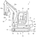
以下、図面を参照して本発明の好ましい実施形態について説明する。まず、本発明に係る旋回駆動装置を有した建設機械の一例として、小型の油圧ショベル(以下、ミニショベルと称する)について、図2を参照して説明する。このミニショベル1は、左右一対のクローラ式走行機構15を備えた走行装置10と、走行装置10の上に水平旋回可能に設けられた車両本体20と、車両本体20の前部に水平旋回(水平揺動)可能に取り付けられたパワーショベル機構30とを有して構成される。
Hereinafter, preferred embodiments of the present invention will be described with reference to the drawings. First, a small hydraulic excavator (hereinafter referred to as a mini excavator) will be described with reference to FIG. 2 as an example of a construction machine having a turning drive device according to the present invention. The mini excavator 1 includes a traveling
走行装置10は、駆動スプロケット12と従動スプロケット13とに巻き掛けられた履帯14から構成されるクローラ式走行機構15を、走行フレーム11の左右に設けて構成される。駆動スプロケット12は、走行油圧モータ18(図3を参照)により回転駆動される。走行フレーム11の後部には、整地作業等を行うためのブレード16が上下揺動自在に設けられており、ブレード16を上下揺動させるブレードシリンダ(油圧シリンダ)16a(図3を参照)が走行フレーム11とブレード16とを繋いで設けられている。走行フレーム11の中央上部には、後述する旋回駆動装置60が設けられており、この旋回駆動装置60により車両本体20が水平旋回可能になっている。
The traveling
車両本体20は、旋回駆動装置60により水平旋回可能に支持された車体フレーム21の上に、作業者の乗車空間を形成する運転キャビン22と、油圧ユニットや電源システム等からなる動力装置Pと、動力装置Pを覆う装置カバー23とを配設して構成される。運転キャビン22内には、作業者が着座するためのシート24、クローラ式走行機構15の作動操作を行う走行操作レバー25(図3を参照)、パワーショベル機構30や旋回駆動装置60の作動操作を行う作業操作レバー26等が配設されている。車体フレーム21の前端には、前方に突出して本体側枢結部27が形成されており、この本体側枢結部27を介してパワーショベル機構30が取り付けられている。
The
パワーショベル機構30は、本体側枢結部27に水平旋回もしくは揺動自在に枢結されたスイング側枢結部35と、このスイング側枢結部35に垂直面内で上下揺動可能に枢結されたブーム31と、ブーム31の先端に同一垂直面内で上下揺動可能に枢結されたアーム32と、アーム32の先端に同一垂直面内で上下揺動可能に枢結されたバケット33とを有して構成される。さらに、ブーム31を上下揺動させるブームシリンダ31aがスイング側枢結部35とブーム31とを繋いで配設され、アーム32を上下揺動させるアームシリンダ32aがブーム31とアーム32とを繋いで配設され、バケット33を上下揺動させるバケットシリンダ33aおよびリンク33bが図示のようにアーム32とバケット33とを繋いで配設されている。なお、スイング側枢結部35を水平旋回させるスイングシリンダ35a(図3を参照)が車体フレーム21とスイング側枢結部35とを繋いで配設されている。なお、上記各シリンダはいずれも油圧シリンダによって構成されている。
The
動力装置Pは、図3に示すように、各機構の油圧アクチュエータ(油圧モータもしくは油圧シリンダ)に作動油を供給する油圧ユニット40と、油圧ユニット40を構成するポンプ用電動モータ45に電力を供給する電源システム50とを有して構成される。油圧ユニット40は、作動油を溜めるタンク41と、所定油圧・流量の作動油を吐出する油圧ポンプ42と、油圧ポンプ42から吐出される作動油を各操作レバー25,26の操作に応じた供給方向および供給量で各油圧アクチュエータに供給する制御を行うコントロールバルブ43と、油圧ポンプ42を駆動するポンプ用電動モータ45とを有して構成される。なお、各操作レバー25,26から出力される操作信号は、後述する制御コントローラ70に入力され、この制御コントローラ70が操作信号に応じた指令信号をコントロールバルブ43に出力してこのコントロールバルブ43の作動を制御するように構成されている。
As shown in FIG. 3, the power unit P supplies power to a
具体的には、コントロールバルブ43は、各操作レバー25,26から入力される操作信号(制御コントローラ70から入力される指令信号)に基づいて、ブレードシリンダ16a、ブームシリンダ31a、アームシリンダ32a、バケットシリンダ33a、スイングシリンダ35a、走行油圧モータ18もしくは後述する旋回油圧モータ65への圧油の供給制御を行う複数の制御弁を備えて構成されている。ポンプ用電動モータ45は、例えばIPMモータ(永久磁石同期型モータ)等の交流モータから構成され、電源システム50から供給される電力により駆動される。
Specifically, the
電源システム50は、リチウムイオン電池等の二次電池からなるバッテリ51と、商用電源からの交流電力を受けてバッテリ51を充電するメイン充電器52と、バッテリ51からの電力をポンプ用電動モータ45および後述する旋回電動モータ66に供給するインバータ53と、旋回電動モータ66からの発電電力の供給を受けてバッテリ51を充電するサブ充電器55とを有して構成される。
The
バッテリ51は、ポンプ用電動モータ45および旋回駆動モータ66の電源として機能し、高定格電圧で高容量に設定されている。メイン充電器52は、商用電源に接続可能なコンセント52aを有し、コンセント52aを接続して商用電源から供給される交流電力を直流電力に変換するとともに出力電圧をバッテリ51に充電できるように制御する充電制御部を備えて構成されている。
The
インバータ53は、バッテリ51からの直流電力を所定の電圧および周波数を有する交流電力に変換して、この交流電力をポンプ用電動モータ45に供給することにより、ポンプ用電動モータ45の出力トルクを制御して所定油圧を油圧ポンプ42から吐出させるように構成されている。また、インバータ53は、変換した交流電力を旋回電動モータ66に供給することにより、旋回電動モータ66の出力トルクを制御するように構成されている。サブ充電器55は、旋回電動モータ66からの発電電力によりバッテリ51を充電する制御を行うように構成されており、これによりバッテリ51は車両本体20の旋回制動時において継続的に充電されるようになっている。
The
このミニショベル1では、コントロールバルブ43およびインバータ53を制御することにより供給される作動油を用いて各油圧アクチュエータが駆動されるが、これらの制御は制御コントローラ70により行われる。制御コントローラ70は、各操作レバー25,26の操作方向および操作量に応じてこの操作レバーから操作信号が入力され、この操作信号に応じてコントロールバルブ43に指令信号を出力して各油圧アクチュエータの作動を制御する。またこのとき、制御コントローラ70は、その作動に必要な作動油を油圧ポンプ42から供給するため、インバータ53にポンプ用電動モータ45の回転数と印加電圧を指令し、インバータ53がこの指令値に基づいた交流電力をポンプ用電動モータ45に供給して作動を制御する。
In this mini excavator 1, each hydraulic actuator is driven using hydraulic oil supplied by controlling the
なお、制御コントローラ70は、各油圧アクチュエータに作動油を供給してミニショベル1を駆動させているときは、ポンプ用電動モータ45を高速で回転させて油圧ポンプ42から作動油を供給し、反対に、各油圧アクチュエータが停止しているときは、ポンプ用電動モータ45を低速で回転させることで、バッテリ51の電力消費を抑えるように構成されている。
The
以上のように構成されたミニショベル1では、運転キャビン22に搭乗した作業者が走行操作レバー25を操作すると、その操作信号に基づいて制御コントローラ70によりコントロールバルブ43の作動制御がなされ、油圧ポンプ42からの圧油を走行油圧モータ18に供給する制御が行われる。これにより、作業者の操作に応じて、左右のクローラ式走行機構15を駆動させてミニショベル1の走行制御を行うことができる。このとき、操作に応じてインバータ53によりバッテリ51からポンプ用電動モータ45に電力を供給する制御が行われ、この電動モータ45により油圧ポンプ42が駆動されて、圧油がコントロールバルブ43に供給されている。
In the mini excavator 1 configured as described above, when an operator who has boarded the driving
また、作業操作レバー26を操作すると、その操作信号に基づいて制御コントローラ70によりコントロールバルブ43の作動制御がなされ、油圧ポンプ42からの圧油をスイングシリンダ35a、ブームシリンダ31a、アームシリンダ32a、バケットシリンダ33aに供給する制御が行われる。これにより、作業者の操作に応じて、車両本体20に対してパワーショベル機構30全体を左右に水平旋回させる作動、スイング側枢結部35に対してブーム31を上下揺動させる作動、ブーム31に対してアーム32を上下揺動させる作動、およびアーム32に対してバケット33を上下揺動させる作動を制御して、掘削作業を行うことができる。また、油圧ポンプ42から送られる圧油は、ブレードシリンダ16a、旋回油圧モータ65にも供給され、作業者の操作に応じてブレード16を上下揺動させる作動、および旋回駆動装置60による車両本体20を水平旋回させる制御も行うことができる。このときも、操作に応じてインバータ53によりバッテリ51からポンプ用駆動モータ45に電力を供給する制御が行われ、この電動モータ45により油圧ポンプ42が駆動されて、圧油がコントロールバルブ43に供給されている。
Further, when the
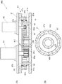
次に、本発明の第1実施形態に係る旋回駆動装置60について図1および図4を用いて詳しく説明する。旋回駆動装置60は、走行フレーム11に対して車体フレーム21を水平旋回可能に支持する旋回ベアリング61と、走行フレーム11と旋回ベアリング61の間に設けられるリング状部材63と、車体フレーム21に旋回駆動力を与える旋回油圧モータ65および旋回電動モータ66と有して構成される。なお、この旋回油圧モータ65が本発明の油圧モータに該当し、旋回電動モータ66が本発明の回生電動モータに該当する。
Next, the turning
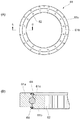
旋回ベアリング61は、金属製のリング状の部材である外輪61aおよび内輪61bからなり、内輪61bが外輪61aに対して内挿されるとともに複数のボール(転動体)61cが外輪61aと内輪61bとの間に介装され、外輪61aと内輪61bとが相対回転できるように構成されている。外輪61aは車体フレーム21の下面に複数のボルト67aによって取り付けられ、内輪61bはリング状部材63を介して走行フレーム11の上面に複数のボルト67bによって取り付けられている。内輪61bの内周面には第1内歯ギヤ62が旋回ベアリング61と同軸に位置して一体に形成されており、この第1内歯ギヤ62が旋回油圧モータ65からの旋回駆動力を受けるようになっている。外輪61aと内輪61bとの間には、その構造上、リング状の微細な隙間が上下に生じるが、この隙間に水や異物が浸入することを防ぐため、上下の隙間をそれぞれ覆うリング状のシール部材68,68が外輪61aもしくは内輪61bに設けられている。
The slewing
リング状部材63は、旋回ベアリング61の内輪61bとほぼ同径の金属製の部材から構成され、走行フレーム11と内輪61bの間に挟まれた状態で内輪61bとともに走行フレーム11の上面に複数のボルト67bによって取り付けられている。リング状部材63の内周面には第2内歯ギヤ64が旋回ベアリング61と同軸に位置して一体に形成されており、この第2内歯ギヤ64が旋回電動モータ66からの旋回駆動力を受けるようになっている。なお、第2内歯ギヤ64の歯数iG2と内輪61bに形成された第1内歯ギヤ62の歯数iG1はそれぞれ任意に設定可能であり、ここでは第2内歯ギヤ64の歯数iG2を第1内歯ギヤ62の歯数iG1よりも多く設定している(iG2>iG1)。The ring-shaped
旋回油圧モータ65は、上述したようにコントロールバルブ43を介して油圧ポンプ42から供給される圧油によって駆動されるように構成されており、車体フレーム21に取り付けられている。旋回油圧モータ65の駆動軸は、旋回ベアリング61の内輪61b内に延びており、この駆動軸に内輪61bの第1内歯ギヤ62と噛み合う第1ピニオン65aが取り付けられている。旋回油圧モータ65の駆動によって第1ピニオン65aが回転すると、その回転駆動力がこれと噛合する第1内歯ギヤ62を介して車体フレーム21に伝達される。第1ピニオン65aは歯数iP1を有し、第1ピニオン65aから第1内歯ギヤ62への回転伝達を行う第1減速比r1は、r1=iG1/iP1となる。The turning
旋回電動モータ66は、インバータ53を介してバッテリ51からの電力を受けて駆動されるとともに、被駆動時には発電機として機能し、その発電電力がサブ充電器55を介してバッテリ51に供給されてこれを充電する(図3も参照)ように構成されたモータジェネレータであり、旋回油圧モータ65と同様に車体フレーム21に取り付けられている。旋回電動モータ66の駆動軸は、旋回ベアリング61(内輪61b)内を通ってリング状部材63内に延びており、この駆動軸にリング状部材63の第2内歯ギヤ64と噛み合う第2ピニオン66aが取り付けられている。旋回電動モータ66の駆動によって第2ピニオン66aが回転すると、その回転駆動力がこれと噛合する第2内歯ギヤ64を介して車体フレーム21に伝達される。第2ピニオン66aは歯数iP2を有し、第2ピニオン66aから第2内歯ギヤ64への回転伝達を行う第2減速比r2は、r2=iG2/iP2となる。なお、第2ピニオン66aの歯数iP2は、旋回油圧モータ65に取り付けられた第1ピニオン65aの歯数iP1よりも少ない歯数になっている。このため、第1減速比r1は第2減速比r2より小さい。The swing
以上ように構成された旋回駆動装置60では、制御コントローラ70によってコントロールバルブ43およびインバータ53を制御することにより供給される作動油および電力を用いて旋回油圧モータ65および旋回電動モータ66を駆動して車両本体20を水平旋回させるようになっている。この制御コントローラ70による旋回油圧モータ65および旋回電動モータ66の制御について図3を併せて参照して説明する。
In the
制御コントローラ70は、作業操作レバー26から車両本体20を旋回させる旨の操作信号(以下、旋回信号と称する)が入力されると、その旋回信号に応じてコントロールバルブ43およびインバータ53を制御して旋回油圧モータ65を駆動させる。すなわち、制御コントローラ70は、旋回信号が旋回を加速させる側に増加する場合には、コントロールバルブ43の開度を大きくするとともに、ポンプ用電動モータ45の回転数を加速して旋回油圧モータ65に供給される作動油の量を増加させる。また、旋回信号が旋回を減速させる側に減少する場合(例えば、旋回を停止させる場合)には、コントロールバルブ43の開度を小さくするとともに、ポンプ用電動モータ45の回転数を減速して旋回油圧モータ65に供給される作動油の量を減少させる。このようにして旋回油圧モータ65を駆動させると、第1ピニオン65aが回転し、第1ピニオン65aと第1内歯ギヤ62の噛み合いから発生する反力が旋回油圧モータ65を介して車両本体20(車体フレーム21)に伝達されるため、車両本体20を走行装置10(走行フレーム11)に対して水平旋回させることができる。
When an operation signal (hereinafter referred to as a turning signal) for turning the vehicle
ところで、旋回(旋回速度)を加速させる場合、特に、停止状態から旋回を開始するとき(旋回起動時)には、旋回油圧モータ65にかかる負荷が大きくなる。そこで本実施形態においては、旋回油圧モータ65にかかる負荷に応じて、旋回油圧モータ65とともに旋回電動モータ66を駆動して、旋回電動モータ66が旋回油圧モータ65による車両本体20の水平旋回をアシストするようになっている。具体的には、制御コントローラ70は、旋回信号の増加量が所定値より大きい(もしくは所定値と等しい)とき(例えば、旋回起動時)に、上述のように旋回油圧モータ65を駆動させるとともに、インバータ53を介してバッテリ51からの電力を旋回電動モータ66に供給して旋回電動モータ66を駆動させる。このように旋回電動モータ66を駆動させると、第2ピニオン66aが回転し、第2ピニオン66aと第2内歯ギヤ64の噛み合いから発生する反力が旋回電動モータ66を介して車両本体20(車体フレーム21)に伝達される。これにより旋回電動モータ66は、旋回油圧モータ65をアシストして車両本体20を水平旋回させる。なおこのとき、ポンプ用電動モータ45の回転数を加速して旋回油圧モータ65に供給される作動油の量を増加させる一方、旋回電動モータ66の出力トルクを減少させ、目標の旋回速度に達した時には、旋回駆動は旋回油圧モータ65のみで駆動される。このようにポンプ用電動モータ45の回転数を制御することで、旋回用油圧ポンプ42でも省エネ化することができる。
By the way, when the turning (turning speed) is accelerated, especially when the turning is started from the stopped state (when turning is started), the load applied to the turning
制御コントローラ70は、旋回信号の増加量が上記所定値より小さいときには、バッテリ51からの電力を旋回電動モータ66に供給せず、上述のように旋回油圧モータ65のみを駆動して車両本体20を水平旋回させる。
When the increase amount of the turning signal is smaller than the predetermined value, the
制御コントローラ70は、車両本体20の旋回作動中において、旋回信号が旋回を減速させる側に減少するとき(例えば、旋回を停止させるとき)には、バッテリ51からの電力を旋回電動モータ66に供給せず、上述のように旋回油圧モータ65のみを駆動して、もしくは旋回油圧モータ65への作動油の供給も停止して車両本体20の水平旋回を減速させる。このとき、旋回電動モータ66は発電機として動作する。つまり、旋回電動モータ66では、第2ピニオン66aと第2内歯ギヤ64の噛み合いによって駆動軸が回転され、この駆動軸に与えられるトルクを電気エネルギーに変換して(エネルギー回生を行って)サブ充電器55を介してバッテリ51を充電するとともに旋回を減速させる。
The
このように旋回油圧モータ65に大きな負荷がかかる場合(例えば、旋回起動時)には、旋回油圧モータ65とともに旋回電動モータ66を駆動することにより、旋回電動モータ66が旋回油圧モータ65をアシストして車両本体20を水平旋回させる。このため、旋回油圧モータ65に要求される駆動馬力が下げられるので、旋回油圧モータ65を小型化することができる。また、旋回油圧モータ65にかかる負荷が比較的小さい場合(例えば、旋回を減速(停止)させる場合)には、旋回電動モータ66が発電機として動作するため、車両本体20の旋回制動中にバッテリ51を断続的に充電することができるので、旋回駆動における消費電力を抑えることができる。
In this way, when a large load is applied to the swing hydraulic motor 65 (for example, when turning is started), the swing
ここで、旋回油圧モータ65の駆動によって回転する第1ピニオン65aは内輪61bに形成された第1内歯ギヤ62と噛み合い、旋回電動モータ66の駆動によって回転する第2ピニオン66aはリング状部材63に形成された第2内歯ギヤ64と噛み合うようになっている。このように、第1ピニオン65aと第2ピニオン66aがそれぞれ異なるギヤと噛み合っているため、各ギヤの歯数を変えることにより第1,第2減速比r1,r2を自由に設定することができる。よって、旋回モータ65,66のトルク配分を最適化する(効率の良い回転数・圧力で旋回モータ65,66を作動させる)ことが可能となり、バッテリ51の電力を有効に利用することができる。
Here, the
また、本実施形態では、第2内歯ギヤ64の歯数iG2を第1内歯ギヤ62の歯数iG1よりも多く設定し、第2ピニオン66aの歯数iP2を第1ピニオン65aの歯数iP1よりも少なく設定して第1減速比r1が第2減速比r2より小さくなるように設定しているため、旋回電動モータ66が発電機として動作するときに、第2ピニオン66aの回転速度を増速させることができる。よって、モータ66の駆動軸を高速回転させることができるので、高回転域での効率の良いエネルギー回生を行ってバッテリ51を充電することが可能となる。In the present embodiment, the number of teeth i G2 of the second
以上説明した第1実施形態の変形例として、内輪61bを車体フレーム21に取り付けるとともに外輪61aを走行フレーム11に取り付け、旋回油圧モータ65および旋回電動モータ66を走行フレーム11に取り付けるように構成しても良い。また、旋回油圧モータの第1ピニオンをリング状部材の内歯ギヤと噛合させ、旋回電動モータの第2ピニオンを内輪の内歯ギヤと噛合させるようにしても良い。
As a modification of the first embodiment described above, the
次に、本発明の第2実施形態に係る旋回駆動装置160について図5を参照して説明する。この旋回駆動装置160においては、内輪61bに一体形成された第1内歯ギヤ62が変速ギヤ列163を介して旋回電動モータ66からの旋回駆動力を受けるように構成されている。また、旋回油圧モータ65の第1ピニオン65aも第1内歯ギヤ62と噛合している。このため、第1内歯ギヤ62が、本発明の第1および第2旋回ギヤを構成する。なお、これ以外の構成は上記実施形態と同一構成であるので、同一部分には同一番号を付してその説明を省略する。
Next, a turning
この変速ギヤ列163は、第1内歯ギヤ62と噛み合う下部ギヤ163aと、第2ピニオン66aと噛み合う上部ギヤ163bとからなり、下部および上部ギヤ163a,163bが同一軸上に一体に結合しており、両者が一体に回転するように車体フレーム21に軸支されて構成されている。なお、旋回油圧モータ65の第1ピニオン65aを、これと同様な構成の変速ギヤ列を介して第1内歯ギヤ62と噛合するように構成しても良い。また、本実施形態以外の他の実施形態においても、同様に、旋回油圧モータおよび旋回電動モータの第1および第2ピニオンを、変速ギヤ列を介して旋回ギヤに回転伝達するように構成しても良い。
The
この旋回駆動装置160では、上記旋回駆動装置60と同様に、旋回油圧モータ65に大きな負荷がかかる場合(例えば、旋回起動時)には、旋回油圧モータ65とともに旋回電動モータ66を駆動することにより、旋回電動モータ66が旋回油圧モータ65をアシストして車両本体20を水平旋回させるため、旋回油圧モータ65を小型化することができる。また、旋回油圧モータ65にかかる負荷が比較的小さい場合(旋回を減速(停止)させる場合)には、旋回電動モータ66が発電機として動作するため、車両本体20の旋回制動中にバッテリ51を断続的に充電することができるので、旋回駆動における消費電力を抑えることができる。
In the turning
また、旋回駆動装置160では、第1内歯ギヤ62が、本発明の第1および第2旋回ギヤを構成するため、両者が同一の歯数を有しているが、第2ピニオン66aの歯数iP2および第1ピニオン65aの歯数iP1を適宜設定することにより、さらに、変速ギヤ列による第2ピニオン66aから第1内歯ギヤ62への回転伝達の減速比(この減速比は第2ピニオン66aと上部ギヤ163bとのギヤ比と、下部ギヤ163aと第1内歯ギヤとのギヤ比により定まる)を設定することにより、第1および第2減速比を自由に設定することができる。よって、旋回モータ65,66のトルク配分を最適化する(効率の良い回転数・圧力で旋回モータ65,66を作動させる)ことが可能となり、バッテリ51の電力を有効に利用することができる。本実施形態では、第2ピニオン66aの歯数iP2を第1ピニオン65aの歯数iP1よりも少なく設定し、且つ変速ギヤ列の上下部ギヤ163a,163bの歯数を適宜設定することにより、第1減速比r1が第2減速比r2より小さくなるように設定しており、旋回電動モータ66が発電機として動作するときに、第2ピニオン66aの回転速度を増速させることができる。よって、モータ66の駆動軸を高速回転させることができるので、高回転域での効率の良いエネルギー回生を行ってバッテリ51を充電することが可能となる。Moreover, in the turning
次に、本発明の第3実施形態に係る旋回駆動装置260について図6を参照して説明する。この旋回駆動装置260においては、車体フレーム21と外輪61aの間に設けられるリング状部材263に一体形成された第2内歯ギヤ264が旋回電動モータ66からの旋回駆動力を受けるように構成されている。さらに、旋回電動モータ66が走行フレーム11に取り付けられて構成されている。なお、これ以外の構成は上記実施形態と同一構成であるので、同一部分には同一番号を付してその説明を省略する。
Next, a turning
リング状部材263は、旋回ベアリング61の外輪61aと略同一外径であり、内輪61bと略同一内径を有する金属製の部材から構成され、車体フレーム21と外輪61aの間に挟まれた状態で外輪61aとともに車体フレーム21の下面に複数のボルト67aによって取り付けられている。リング状部材263の内周面には第2内歯ギヤ264が一体に形成されており、この第2内歯ギヤ264が旋回電動モータ66からの旋回駆動力を受けるようになっている。第2内歯ギヤ264の歯数iG2と内輪61bに形成された第1内歯ギヤ62の歯数iG1はそれぞれ任意に設定可能であり、ここでは第2内歯ギヤ264の歯数iG2を第1内歯ギヤ62の歯数iG1よりも多く設定している(iG2>iG1)The ring-shaped
旋回電動モータ66は、上述したようにモータジェネレータから構成されており、走行フレーム11に取り付けられている。旋回電動モータ66の駆動軸は、旋回ベアリング61(内輪61b)内を通ってリング状部材263内に延びており、この駆動軸にリング状部材263に形成された第2内歯ギヤ264と噛み合う第2ピニオン66aが取り付けられている。旋回電動モータ66の駆動によって第2ピニオン66aが回転すると、第2ピニオン66aおよび第2内歯ギヤ264の噛み合いにより旋回電動モータ66からの旋回駆動力が車体フレーム21に伝達される。これにより、車体フレーム21を走行フレーム11に対して水平旋回できるようになっている。
The turning
なお、旋回油圧モータ65は、上記実施形態と同様に車体フレーム21に取り付けられており、その駆動軸に内輪61bに形成された第1内歯ギヤ62と噛み合う第1ピニオン65aが取り付けられている。よって、旋回油圧モータ65を駆動して第1ピニオン65aを回転させることにより、車両本体20(車体フレーム21)を走行装置(走行フレーム11)に対して水平旋回できるようにもなっている。
The turning
このように構成された旋回駆動装置260では、上記旋回駆動装置と同様に、旋回油圧モータ65に大きな負荷がかかる場合(例えば、旋回起動時)には、旋回油圧モータ65とともに旋回電動モータ66を駆動することにより、旋回電動モータ66が旋回油圧モータ65をアシストして車両本体20を水平旋回させるため、旋回油圧モータ65を小型化することができる。また、旋回油圧モータ65にかかる負荷が比較的小さい場合(旋回を減速(停止)させる場合)には、旋回電動モータ66が発電機として動作するため、車両本体20の旋回制動中にバッテリ51を断続的に充電することができるので、旋回駆動における消費電力を抑えることができる。
In the
また、旋回駆動装置260では、第1内歯ギヤ62と第2内歯ギヤ264の歯数および第1,第2ピニオン65a,66aの歯数の設定を変えることにより、第1および第2減速比r1,r2を自由に設定することができる。よって、旋回モータ65,66のトルク配分を最適化する(効率の良い回転数・圧力で旋回モータ65,66を作動させる)ことが可能となり、バッテリ51の電力を有効に利用することができる。
In the turning
本実施形態では、第2内歯ギヤ264の歯数iG2を第1内歯ギヤ62の歯数iG1よりも多く設定し、第2ピニオン66aの歯数iP2を第1ピニオン65aの歯数iP1よりも少なく設定して第1減速比r1が第2減速比r2より小さくなるように設定しているため、旋回電動モータ66が発電機として動作するときに、第2ピニオン66aの回転速度を増速させることができる。よって、旋回電動モータ66の駆動軸を高速回転させることができるので、高回転域での効率の良いエネルギー回生を行ってバッテリ51を充電することが可能となる。また、旋回駆動装置260では、旋回電動モータ66が走行フレーム11に取り付けられているので、車体フレーム21での省スペース化を実現することができる。In the present embodiment, the number of teeth i G2 of the second
以上説明した第3実施形態の変形例として、内輪61bを車体フレーム21に取り付けるとともに外輪61aを走行フレーム11に取り付け、旋回油圧モータ65を走行フレーム11に取り付け、旋回電動モータ66を車体フレーム21に取り付けるように構成しても良い。
As a modification of the third embodiment described above, the
次に、本発明の第4実施形態に係る旋回駆動装置360について図7を参照して説明する。この旋回駆動装置360においては、外輪61aの外周面に一体形成された外歯ギヤ69が旋回電動モータ66からの旋回駆動力を受けるように構成されている。さらに、旋回電動モータ66が走行フレーム11に取り付けられて構成されている。なお、これ以外の構成は上記第1実施形態と同一構成であるので、同一部分には同一番号を付してその説明を省略する。
Next, a turning
旋回ベアリング61は、上述したように外輪61aの外周面に外歯ギヤ69が一体に形成されており、この外歯ギヤ69が旋回電動モータ66からの旋回駆動力を受けるようになっている。なお、外歯ギヤ69の歯数iG2と内輪61bに形成された第1内歯ギヤ62の歯数iG1はそれぞれ任意に設定可能であり、外歯ギヤ69の歯数iG2は1内歯ギヤ62の歯数iG1よりも多い(iG2>iG1)。In the slewing bearing 61, as described above, the
旋回電動モータ66は、上述したようにモータジェネレータから構成されており、走行フレーム11に取り付けられている。旋回電動モータ66の駆動軸は、旋回ベアリング61の外側を延びており、この駆動軸に外輪61aに形成された外歯ギヤ69と噛み合う第2ピニオン66aが取り付けられている。旋回電動モータ66の駆動によって第2ピニオン66aが回転すると、第2ピニオン66aと外歯ギヤ69の噛み合いにより旋回電動モータ66の旋回駆動力が車体フレーム21に伝達される。これにより、車体フレーム21を走行フレーム11に対して水平旋回できるようになっている。
The turning
なお、旋回油圧モータ65は、上記実施形態と同様に車体フレーム21に取り付けられており、その駆動軸に内輪61bに形成された第1内歯ギヤ62と噛み合う第1ピニオン65aが取り付けられている。よって、旋回油圧モータ65を駆動して第1ピニオン65aを回転させることにより、車体フレーム21を走行フレーム11に対して水平旋回できるようにもなっている。
The turning
このように構成された旋回駆動装置360では、上記旋回駆動装置と同様に、旋回油圧モータ65に大きな負荷がかかる場合(例えば、旋回起動時)には、旋回油圧モータ65とともに旋回電動モータ66を駆動することにより、旋回電動モータ66が旋回油圧モータ65をアシストして車両本体20を水平旋回させるため、旋回油圧モータ65を小型化することができる。また、旋回油圧モータ65にかかる負荷が比較的小さい場合(旋回を減速(停止)させる場合)には、旋回電動モータ66が発電機として動作するため、車両本体20の旋回制動中にバッテリ51を断続的に充電することができるので、旋回駆動における消費電力を抑えることができる。
In the
また、旋回駆動装置360では、第1内歯ギヤ62と外歯ギヤ69の歯数および第1,第2ピニオン65a,66aの歯数を変えることにより、第1および第2減速比r1,r2を自由に設定することができる。よって、旋回モータ65,66のトルク配分を最適化する(効率の良い回転数・圧力で旋回モータ65,66を作動させる)ことが可能となり、バッテリ51の電力を有効に利用することができる。ここでは外歯ギヤ69の歯数iG2を第1内歯ギヤ62の歯数iG1よりも多く設定し、第2ピニオン66aの歯数iP2を第1ピニオン65aの歯数iP1よりも少なく設定して第1減速比r1が第2減速比r2より小さくなるように設定しているため、旋回電動モータ66が発電機として動作するときに、第2ピニオン66aの回転速度を増速させることができる。よって、旋回電動モータ66の駆動軸を高速回転させることができるので、高回転域での効率の良いエネルギー回生を行ってバッテリ51を充電することが可能となる。また、旋回駆動装置360では、旋回電動モータ66が走行フレーム11に取り付けられているので、車体フレーム21での省スペース化を実現することができる。Further, in the turning
以上説明した第4実施形態の変形例として、内輪61bを車体フレーム21に取り付けるとともに外輪61aを走行フレーム11に取り付け、旋回油圧モータ65を走行フレーム11に取り付け、旋回電動モータ66を車体フレーム21に取り付けるように構成しても良い。
As a modification of the fourth embodiment described above, the
次に、本発明の第5実施形態に係る旋回駆動装置460について図8を参照して説明する。この旋回駆動装置460においては、旋回ベアリング61(内輪61b)の内側にリング状部材463が設けられ、このリング状部材463の外周面に一体形成された外歯ギヤ469が旋回油圧モータ65からの旋回駆動力を受けるように構成されている。さらに、内輪61bに形成された第1内歯ギヤ62が旋回電動モータ66からの旋回駆動力を受けるように構成されている。なお、これ以外の構成は上記第1実施形態と同一構成であるので、同一部分には同一番号を付してその説明を省略する。
Next, a turning
リング状部材463は、旋回ベアリング61の内輪61bよりも小径の金属製の部材から構成され、内輪61bの内側において内輪61bと略同心となる状態で走行フレーム11の上面に複数のボルト467によって取り付けられている。リング状部材463の外周面には外歯ギヤ469が一体に形成されており、この外歯ギヤ469が旋回油圧モータ65からの旋回駆動力を受けるようになっている。なお、外歯ギヤ469の歯数iG1と内輪61bに形成された第1内歯ギヤ62の歯数iG2はそれぞれ任意に設定可能であり、ここでは外歯ギヤ469の歯数iG1を第1内歯ギヤ62の歯数iG2よりも少なく設定している(iG1>iG2)。The ring-shaped
旋回油圧モータ65は、上記実施形態と同様に車体フレーム21に取り付けられている。旋回油圧モータ65の駆動軸は、旋回ベアリング61(内輪61b)内に延びており、この駆動軸にリング状部材463に形成された外歯ギヤ469と噛み合う第1ピニオン65aが取り付けられている。旋回油圧モータ65の駆動によって第1ピニオン65aが回転すると、第1ピニオン65aおよび外歯ギヤ469の噛み合いにより旋回油圧モータ65からの旋回駆動力が車体フレーム21に伝達される。これにより、車体フレーム21を走行フレーム11に対して水平旋回できるようになっている。
The turning
旋回電動モータ66は、上記実施形態と同様に車体フレーム21に取り付けられており、その駆動軸に内輪61bに形成された第1内歯ギヤ62と噛み合う第2ピニオン66aが取り付けられている。よって、旋回電動モータ66を駆動して第2ピニオン66aを回転させることにより、車体フレーム21を走行フレーム11に対して水平旋回できるようになっている。
The turning
このように構成された旋回駆動装置460では、上記旋回駆動装置と同様に、旋回油圧モータ65に大きな負荷がかかる場合(例えば、旋回起動時)には、旋回油圧モータ65とともに旋回電動モータ66を駆動することにより、旋回電動モータ66が旋回油圧モータ65をアシストして車両本体20を水平旋回させるため、旋回油圧モータ65を小型化することができる。また、旋回油圧モータ65にかかる負荷が比較的小さい場合(旋回を減速(停止)させる場合)には、旋回電動モータ66が発電機として動作するため、車両本体20の旋回制動中にバッテリ51を断続的に充電することができるので、旋回駆動における消費電力を抑えることができる。
In the
また、旋回駆動装置460では、第1内歯ギヤ62と外歯ギヤ469の歯数を変えることにより第1,第2ピニオン65a,66aの回転速度比を自由に設定することができる。よって、旋回モータ65,66のトルク配分を最適化する(効率の良い回転数・圧力で旋回モータ65,66を作動させる)ことが可能となり、バッテリ51の電力を有効に利用することができる。ここでは、外歯ギヤ469の歯数iG1を第1内歯ギヤ62の歯数iG2よりも少なく設定し、第2ピニオン66aの歯数iP2を第1ピニオン65aの歯数iP1よりも少なく設定しているため、第2ピニオン66aの回転速度を増速させることができる。よって、旋回電動モータ66が発電機として動作するときに、モータ66の駆動軸を高速回転させることができるので、より多くのエネルギー回生を行ってバッテリ51を充電することが可能となる。また、旋回駆動装置460では、内輪61b、リング状部材463および走行フレーム11によって囲まれる空間内において、第1ピニオン65aと外歯ギヤ469、および、第2ピニオン66aと第1内歯ギヤ62がそれぞれ噛み合うように構成できるので、この空間内にグリス(潤滑剤)を装入しておくことができる。In the turning
なお、上記実施形態において、旋回駆動装置60,160,460では、外輪61a、旋回油圧モータ65および旋回電動モータ66が車体フレーム21に設けられているが、外輪61a、旋回油圧モータ65および旋回電動モータ66が走行フレーム11に設けられる構成としてもよい。なおこのとき、内輪61bは車体フレーム21に取り付けられて構成される。また、旋回駆動装置460では、リング状部材463も車体フレーム21に取り付けられて構成される。
In the above-described embodiment, in the turning
また、旋回駆動装置260,360において、旋回油圧モータ65を走行フレーム11に設け、旋回電動モータ66を車体フレーム21に設ける構成としてもよい。また、旋回駆動装置260において、外輪61aとリング状部材263を一体に形成して1つの部材として構成してもよい。また、旋回駆動装置360において、外輪61aを走行フレーム11に取り付け、内輪61bを車体フレーム21に取り付ける構成としてもよい。なおこのとき、外歯ギヤ69を介して旋回駆動力を与えるモータが車体フレーム21に設けられ、第1内歯ギヤ62を介して旋回駆動力を与えるモータが走行フレーム11に設けられて構成される。
Further, in the turning
また、上記実施形態では、旋回油圧モータ65にかかる負荷を旋回信号の増加量によって判定する構成であるが、例えば、油圧ポンプ42の吐出油圧やポンプ用電動モータ454に印加される電圧によって、旋回油圧モータ65にかかる負荷を判定する構成としてもよい。また、上記実施形態において、旋回ベアリングは、ボールベアリング式によって構成されているが、これに代えてローラベアリング式等によって構成してもよい。また、各旋回モータ65,66は、変速機構を備える構造のモータによって構成してもよい。
In the above-described embodiment, the load applied to the swing
また、上記実施形態において、走行油圧モータ18による走行から減速走行を行うときに回転されて減速エネルギーを回生して発電する回生発電機を走行油圧モータ18に設けて構成してもよい。同様に、旋回減速作動時に回転駆動されて旋回を減速させるエネルギーを回生して発電する回生発電機を旋回油圧モータ65に設けて構成してもよい。さらに、コントロールバルブ43から作動油タンクに戻る作動油の流れを受けて発電を行う回生発電機を設けてもよい。
In the above embodiment, the traveling
1 油圧ショベル(建設機械) 10 走行装置(走行体)
20 車両本体(旋回体)
60、160、260、360,460 旋回駆動装置
61 旋回ベアリング 61a 外輪
61b 内輪 62 第1内歯ギヤ
63,263,463 リング状部材
64,264 第2内歯ギヤ
65 旋回油圧モータ 65a 第1ピニオン
66 旋回電動モータ 66a 第2ピニオン
69,469 外歯ギヤ 163 変速ギヤ列
163a 下部ギヤ 163b 上部ギヤ1 Hydraulic excavator (Construction machine) 10 Traveling device (traveling body)
20 Vehicle body (swivel body)
60, 160, 260, 360, 460
Claims (17)
前記走行体に対して前記旋回体を旋回動自在に支持する旋回ベアリングと、
前記走行体および前記旋回体のいずれか一方の側に、前記旋回ベアリングと同軸上に位置して設けられた第1旋回ギヤ部材と、
前記走行体および前記旋回体における前記第1旋回ギヤ部材が設けられた側もしくは他方の側に、前記旋回ベアリングと同軸上に位置して設けられた第2旋回ギヤ部材と、
前記第1旋回ギヤ部材のギヤ部と噛合する第1ピニオンギヤを有し、油圧力を用いて前記第1ピニオンギヤを回転駆動して前記第1旋回ギヤ部材を回転駆動可能な油圧モータと、
前記第2旋回ギヤ部材と噛合する第2ピニオンギヤを有し、電力を用いて前記第2ピニオンギヤを回転駆動して前記第2旋回ギヤ部材を回転駆動可能であり、且つ前記第2旋回ギヤ部材の回転による前記第2ピニオンギヤの回転駆動により回生発電が可能な回生電動モータとを備え、
前記第1ピニオンギヤにより前記第1旋回ギヤ部材へ回転伝達を行う第1減速比が、前記第2ピニオンギヤにより前記第2旋回ギヤ部材へ回転伝達を行う第2減速比と相違するように構成されたことを特徴とする旋回駆動装置。 A swivel drive device that supports a revolving body on a traveling body so as to be capable of revolving, and that revolves the revolving body,
A swivel bearing that supports the swivel so that the swivel can swivel with respect to the traveling body;
A first swivel gear member provided on one side of the traveling body and the swivel body and positioned coaxially with the swivel bearing;
A second slewing gear member provided coaxially with the slewing bearing on the side where the first slewing gear member is provided or the other side of the traveling body and the slewing body;
A hydraulic motor having a first pinion gear meshing with a gear portion of the first turning gear member, and capable of rotationally driving the first turning gear member by rotationally driving the first pinion gear using hydraulic pressure;
A second pinion gear that meshes with the second swivel gear member; the second pinion gear can be rotationally driven using electric power to rotate the second swivel gear member; and A regenerative electric motor capable of generating regenerative power by rotating the second pinion gear by rotation;
The first reduction ratio for transmitting rotation to the first turning gear member by the first pinion gear is different from the second reduction ratio for transmitting rotation to the second turning gear member by the second pinion gear. A turning drive device characterized by that.
前記第1旋回ギヤ部材が前記内輪に一体結合して設けられた第1ギヤを有して構成され、前記第2旋回ギヤ部材が前記内輪に一体結合して設けられるとともに前記第1ギヤと歯数の異なる第2ギヤを有して構成され、
前記油圧モータは前記外輪が設けられる側に設けられ、前記第1ピニオンギヤが前記第1ギヤと噛合し、
前記回生電動モータは前記外輪が設けられる側に設けられ、前記第2ピニオンギヤが前記第2ギヤと噛合することを特徴とする請求項1〜3のいずれかに記載の旋回駆動装置。 An outer ring to which the slewing bearing is attached to one of the traveling body and the slewing body, and an outer ring provided on the inner diameter side of the outer ring via a rolling element so as to be relatively rotatable, and attached to the other of the traveling body and the turning body And an inner ring to be configured,
The first turning gear member is configured to have a first gear integrally connected to the inner ring, the second turning gear member is integrally connected to the inner ring, and the first gear and teeth Configured with different numbers of second gears,
The hydraulic motor is provided on the side where the outer ring is provided, the first pinion gear meshes with the first gear,
The turning drive device according to any one of claims 1 to 3, wherein the regenerative electric motor is provided on a side where the outer ring is provided, and the second pinion gear meshes with the second gear.
前記第1旋回ギヤ部材が前記内輪に一体結合して設けられた第1ギヤを有して構成され、前記第2旋回ギヤ部材が前記外輪に一体結合して設けられるとともに前記第1ギヤと歯数の異なる第2ギヤを有して構成され、
前記油圧モータは前記外輪が設けられる側に設けられ、前記第1ピニオンギヤが前記第1ギヤと噛合し、
前記回生電動モータは前記内輪が設けられる側に設けられ、前記第2ピニオンギヤが前記第2ギヤと噛合することを特徴とする請求項1〜3のいずれかに記載の旋回駆動装置。 An outer ring to which the slewing bearing is attached to one of the traveling body and the slewing body, and an outer ring provided on the inner diameter side of the outer ring via a rolling element so as to be relatively rotatable, and attached to the other of the traveling body and the turning body And an inner ring to be configured,
The first turning gear member has a first gear integrally connected to the inner ring, the second turning gear member is integrally connected to the outer ring, and the first gear and teeth Configured with different numbers of second gears,
The hydraulic motor is provided on the side where the outer ring is provided, the first pinion gear meshes with the first gear,
The turning drive device according to any one of claims 1 to 3, wherein the regenerative electric motor is provided on a side where the inner ring is provided, and the second pinion gear meshes with the second gear.
前記第1旋回ギヤ部材が前記外輪に一体結合して設けられた第1ギヤを有して構成され、前記第2旋回ギヤ部材が前記内輪に一体結合して設けられるとともに前記第1ギヤと歯数の異なる第2ギヤを有して構成され、
前記油圧モータは前記内輪が設けられる側に設けられ、前記第1ピニオンギヤが前記第1ギヤと噛合し、
前記回生電動モータは前記外輪が設けられる側に設けられ、前記第2ピニオンギヤが前記第2ギヤと噛合することを特徴とする請求項1〜3のいずれかに記載の旋回駆動装置。 An outer ring to which the slewing bearing is attached to one of the traveling body and the slewing body, and an outer ring provided on the inner diameter side of the outer ring via a rolling element so as to be relatively rotatable, and attached to the other of the traveling body and the turning body And an inner ring to be configured,
The first turning gear member includes a first gear provided integrally with the outer ring, the second turning gear member is provided integrally with the inner ring, and the first gear and teeth Configured with different numbers of second gears,
The hydraulic motor is provided on the side where the inner ring is provided, the first pinion gear meshes with the first gear,
The turning drive device according to any one of claims 1 to 3, wherein the regenerative electric motor is provided on a side where the outer ring is provided, and the second pinion gear meshes with the second gear.
前記第1旋回ギヤ部材が前記外輪に一体結合して設けられた第1ギヤを有して構成され、前記第2旋回ギヤ部材が前記外輪に一体結合して設けられるとともに前記第1ギヤと歯数の異なる第2ギヤを有して構成され、
前記油圧モータは前記内輪が設けられる側に設けられ、前記第1ピニオンギヤが前記第1ギヤと噛合し、
前記回生電動モータは前記内輪が設けられる側に設けられ、前記第2ピニオンギヤが前記第2ギヤと噛合することを特徴とする請求項1〜3のいずれかに記載の旋回駆動装置。 An outer ring to which the slewing bearing is attached to one of the traveling body and the slewing body, and an outer ring provided on the inner diameter side of the outer ring via a rolling element so as to be relatively rotatable, and attached to the other of the traveling body and the turning body And an inner ring to be configured,
The first turning gear member is configured to have a first gear integrally connected to the outer ring, and the second turning gear member is integrally connected to the outer ring, and the first gear and teeth Configured with different numbers of second gears,
The hydraulic motor is provided on the side where the inner ring is provided, the first pinion gear meshes with the first gear,
The turning drive device according to any one of claims 1 to 3, wherein the regenerative electric motor is provided on a side where the inner ring is provided, and the second pinion gear meshes with the second gear.
前記制御コントローラは、前記旋回油圧モータにかかる負荷に応じて、前記旋回油圧モータとともに前記旋回電動モータを駆動することを特徴とする請求項1〜15のいずれかに記載の旋回駆動装置。 A control controller for controlling the hydraulic oil supplied to the swing hydraulic motor and the electric power supplied to the swing electric motor to control the drive of the swing hydraulic motor and the swing electric motor;
16. The turning drive device according to claim 1, wherein the control controller drives the turning electric motor together with the turning hydraulic motor in accordance with a load applied to the turning hydraulic motor.
Priority Applications (1)
| Application Number | Priority Date | Filing Date | Title |
|---|---|---|---|
| JP2011524656A JP5342000B2 (en) | 2009-07-30 | 2010-07-26 | Slewing drive |
Applications Claiming Priority (4)
| Application Number | Priority Date | Filing Date | Title |
|---|---|---|---|
| JP2009178349 | 2009-07-30 | ||
| JP2009178349 | 2009-07-30 | ||
| PCT/JP2010/004751 WO2011013347A1 (en) | 2009-07-30 | 2010-07-26 | Swing drive device |
| JP2011524656A JP5342000B2 (en) | 2009-07-30 | 2010-07-26 | Slewing drive |
Publications (2)
| Publication Number | Publication Date |
|---|---|
| JPWO2011013347A1 JPWO2011013347A1 (en) | 2013-01-07 |
| JP5342000B2 true JP5342000B2 (en) | 2013-11-13 |
Family
ID=43529019
Family Applications (1)
| Application Number | Title | Priority Date | Filing Date |
|---|---|---|---|
| JP2011524656A Active JP5342000B2 (en) | 2009-07-30 | 2010-07-26 | Slewing drive |
Country Status (3)
| Country | Link |
|---|---|
| EP (1) | EP2460941B1 (en) |
| JP (1) | JP5342000B2 (en) |
| WO (1) | WO2011013347A1 (en) |
Families Citing this family (12)
| Publication number | Priority date | Publication date | Assignee | Title |
|---|---|---|---|---|
| JP2013144888A (en) * | 2012-01-13 | 2013-07-25 | Yanmar Co Ltd | Revolution type electric work vehicle |
| JP5873456B2 (en) * | 2013-04-05 | 2016-03-01 | 川崎重工業株式会社 | Work machine drive control system, work machine including the same, and drive control method thereof |
| DE102013212868A1 (en) | 2013-07-02 | 2015-01-22 | Volkswagen Aktiengesellschaft | Electric drive |
| DE102014203999A1 (en) | 2014-03-05 | 2015-09-24 | Volkswagen Aktiengesellschaft | Electric drive, method for its operation and serial hybrid powertrain for a motor vehicle |
| TWI583122B (en) * | 2014-05-28 | 2017-05-11 | yin-ping Xu | Drive the rotating device |
| CN106586851B (en) * | 2017-03-02 | 2018-01-02 | 李爱冰 | A rotating structure for a low-consumption pendant tower |
| CN107473106B (en) * | 2017-07-31 | 2018-11-20 | 李祖彦 | A kind of hoisting machinery rotating device |
| CN109653282B (en) * | 2019-01-18 | 2021-03-16 | 安徽佳明环保科技股份有限公司 | Agitating unit convenient to desilting |
| DE102020108856A1 (en) | 2020-03-31 | 2021-09-30 | Liebherr-Hydraulikbagger Gmbh | Mobile work machine |
| IT202200005456A1 (en) * | 2022-03-21 | 2023-09-21 | Cnh Ind Italia Spa | SHOVEL OR EXCAVATOR |
| CN116477502B (en) * | 2023-04-23 | 2026-02-10 | 武汉理工大学 | A mode-switchable tower crane slewing vibration damping mechanism |
| IT202300013566A1 (en) * | 2023-06-29 | 2024-12-29 | Cnh Ind Italia Spa | IMPROVED ROTARY JOINT FOR WORK VEHICLE |
Citations (3)
| Publication number | Priority date | Publication date | Assignee | Title |
|---|---|---|---|---|
| JP2004360216A (en) * | 2003-06-02 | 2004-12-24 | Sumitomo (Shi) Construction Machinery Manufacturing Co Ltd | Swing driving device for construction machinery |
| JP2005290882A (en) * | 2004-04-01 | 2005-10-20 | Kobelco Contstruction Machinery Ltd | Slewing working machine |
| JP2008297754A (en) * | 2007-05-30 | 2008-12-11 | Daikin Ind Ltd | Rotating body drive device |
Family Cites Families (4)
| Publication number | Priority date | Publication date | Assignee | Title |
|---|---|---|---|---|
| DE3102532C1 (en) * | 1981-01-27 | 1982-09-30 | O & K Orenstein & Koppel Ag, 1000 Berlin | Swivel drive for conveyor devices with a swiveling superstructure and a swiveling loading belt boom |
| JPH10331197A (en) * | 1997-05-28 | 1998-12-15 | Kubota Corp | Backhoe |
| JP3144562B2 (en) * | 1997-07-11 | 2001-03-12 | 株式会社小松製作所 | Work machine |
| JP2007247374A (en) | 2006-03-15 | 2007-09-27 | Hiroshi Kondo | Hydraulic excavator equipped with generator operated by revolution |
-
2010
- 2010-07-26 EP EP10804100.5A patent/EP2460941B1/en active Active
- 2010-07-26 WO PCT/JP2010/004751 patent/WO2011013347A1/en not_active Ceased
- 2010-07-26 JP JP2011524656A patent/JP5342000B2/en active Active
Patent Citations (3)
| Publication number | Priority date | Publication date | Assignee | Title |
|---|---|---|---|---|
| JP2004360216A (en) * | 2003-06-02 | 2004-12-24 | Sumitomo (Shi) Construction Machinery Manufacturing Co Ltd | Swing driving device for construction machinery |
| JP2005290882A (en) * | 2004-04-01 | 2005-10-20 | Kobelco Contstruction Machinery Ltd | Slewing working machine |
| JP2008297754A (en) * | 2007-05-30 | 2008-12-11 | Daikin Ind Ltd | Rotating body drive device |
Also Published As
| Publication number | Publication date |
|---|---|
| EP2460941A1 (en) | 2012-06-06 |
| EP2460941B1 (en) | 2019-01-09 |
| JPWO2011013347A1 (en) | 2013-01-07 |
| EP2460941A4 (en) | 2016-12-07 |
| WO2011013347A1 (en) | 2011-02-03 |
Similar Documents
| Publication | Publication Date | Title |
|---|---|---|
| JP5342000B2 (en) | Slewing drive | |
| JP3877901B2 (en) | Excavator | |
| JP4517703B2 (en) | Swivel work machine | |
| JP5600274B2 (en) | Electro-hydraulic drive system for work machines | |
| JP4179465B2 (en) | Construction machinery | |
| JP5356427B2 (en) | Hybrid construction machine | |
| JP5180518B2 (en) | Construction machine with hybrid drive | |
| JP4732284B2 (en) | Hybrid construction machine that converts kinetic energy of inertial body into electrical energy | |
| WO2001000935A1 (en) | Drive device of working machine | |
| CN102575456A (en) | Construction machinery | |
| JP2001016704A (en) | Hydraulic driving gear | |
| JP2000289983A (en) | Crane | |
| JP2006336432A (en) | Work machine | |
| JP3828679B2 (en) | Hybrid construction machinery | |
| CN214994175U (en) | Hydraulic-free hybrid power excavator | |
| JP4425769B2 (en) | Work machine | |
| JP2013170406A (en) | Construction machine equipped with hybrid drive device, regeneration device provided in the same, and regeneration method | |
| JP2003082707A (en) | Electric construction machine and electric excavator | |
| JP2011241540A (en) | Driving device for construction machine rotation mechanism | |
| JP6067414B2 (en) | Swivel construction machine | |
| US20120302386A1 (en) | Triple hybrid transmission system | |
| JP2006336845A (en) | Working machine | |
| JP2010047125A (en) | Traveling control circuit of hybrid construction machine | |
| JP2006336847A (en) | Energy regenerative device | |
| JP5399105B2 (en) | Hybrid work machine |
Legal Events
| Date | Code | Title | Description |
|---|---|---|---|
| A621 | Written request for application examination |
Free format text: JAPANESE INTERMEDIATE CODE: A621 Effective date: 20130116 |
|
| TRDD | Decision of grant or rejection written | ||
| A01 | Written decision to grant a patent or to grant a registration (utility model) |
Free format text: JAPANESE INTERMEDIATE CODE: A01 Effective date: 20130726 |
|
| A61 | First payment of annual fees (during grant procedure) |
Free format text: JAPANESE INTERMEDIATE CODE: A61 Effective date: 20130808 |
|
| R150 | Certificate of patent or registration of utility model |
Ref document number: 5342000 Country of ref document: JP Free format text: JAPANESE INTERMEDIATE CODE: R150 Free format text: JAPANESE INTERMEDIATE CODE: R150 |
|
| R250 | Receipt of annual fees |
Free format text: JAPANESE INTERMEDIATE CODE: R250 |
|
| R250 | Receipt of annual fees |
Free format text: JAPANESE INTERMEDIATE CODE: R250 |
|
| R250 | Receipt of annual fees |
Free format text: JAPANESE INTERMEDIATE CODE: R250 |
|
| R250 | Receipt of annual fees |
Free format text: JAPANESE INTERMEDIATE CODE: R250 |
|
| R250 | Receipt of annual fees |
Free format text: JAPANESE INTERMEDIATE CODE: R250 |
|
| R250 | Receipt of annual fees |
Free format text: JAPANESE INTERMEDIATE CODE: R250 |
|
| R250 | Receipt of annual fees |
Free format text: JAPANESE INTERMEDIATE CODE: R250 |
|
| R250 | Receipt of annual fees |
Free format text: JAPANESE INTERMEDIATE CODE: R250 |
|
| R250 | Receipt of annual fees |
Free format text: JAPANESE INTERMEDIATE CODE: R250 |
|
| R250 | Receipt of annual fees |
Free format text: JAPANESE INTERMEDIATE CODE: R250 |