JP5395000B2 - Method and apparatus for measuring remaining thickness of molten cast refractory - Google Patents
Method and apparatus for measuring remaining thickness of molten cast refractory Download PDFInfo
- Publication number
- JP5395000B2 JP5395000B2 JP2010149659A JP2010149659A JP5395000B2 JP 5395000 B2 JP5395000 B2 JP 5395000B2 JP 2010149659 A JP2010149659 A JP 2010149659A JP 2010149659 A JP2010149659 A JP 2010149659A JP 5395000 B2 JP5395000 B2 JP 5395000B2
- Authority
- JP
- Japan
- Prior art keywords
- molten cast
- cast refractory
- thickness
- electromagnetic wave
- heat insulating
- Prior art date
- Legal status (The legal status is an assumption and is not a legal conclusion. Google has not performed a legal analysis and makes no representation as to the accuracy of the status listed.)
- Active
Links
Images


Landscapes
- Length-Measuring Devices Using Wave Or Particle Radiation (AREA)
- Glass Melting And Manufacturing (AREA)
Description
本発明は、ガラス溶解窯に使用される溶融鋳造耐火物の残厚測定方法及び測定装置に係り、特に、操業中のガラス溶解窯の側壁に用いられている溶融鋳造耐火物の残厚を、操業を妨げることなく測定できる測定方法及び測定装置に関する。 The present invention relates to a method and a measurement apparatus for measuring the remaining thickness of a molten cast refractory used in a glass melting furnace, and in particular, the remaining thickness of a molten cast refractory used on the side wall of a glass melting furnace in operation. The present invention relates to a measurement method and a measurement apparatus that can measure without disturbing operations.
ガラス溶解窯は、ガラスを溶融させるために非常に高温で使用され、かつ、溶融したガラスへの悪影響を及ぼさないような性質を有する溶融鋳造耐火物を側壁に用いて構成されている。 The glass melting kiln is constructed using a molten cast refractory on the side wall, which is used at a very high temperature for melting glass and has a property that does not adversely affect the molten glass.
このガラス溶解窯においては、操業を継続していくうちに、溶融ガラスと接触している溶融鋳造耐火物が徐々に浸食され、その厚みが減少していく。そして、その厚さが所定範囲よりも薄くなった場合に、窯の修理を行って延命を図ったり、窯の寿命として窯を停止したりする。 In this glass melting furnace, as the operation continues, the molten cast refractory that is in contact with the molten glass is gradually eroded and its thickness decreases. And when the thickness becomes thinner than the predetermined range, the kiln is repaired to extend the life, or the kiln is stopped as the life of the kiln.
これを適切に行わずに限界を超えて操業を継続してしまうと、溶融鋳造耐火物に穴が開いて、溶融ガラス素地が窯外へ漏れてしまう重大な事故などが発生してしまう。その一方で、安全を見て、まだ十分に残厚があり、耐用が充分なのに窯を停止してしまった場合は、コスト的にも大きなロスとなってしまう。 If this operation is not performed properly and the operation is continued beyond the limit, a serious accident may occur in which the molten glass refractory is perforated and the molten glass body leaks out of the kiln. On the other hand, looking at safety, if the kiln is stopped even though there is still a sufficient remaining thickness, and the durability is sufficient, a large loss is caused in terms of cost.
以上の理由で、耐火物の残厚を操業を継続しながら把握することは、非常に重要であり、ガラス窯ユーザーからの強い要求がある。 For the above reasons, it is very important to grasp the remaining thickness of the refractory while continuing the operation, and there is a strong demand from the glass kiln user.
この耐火物の残厚を測定するために、従来用いられていた方法としては、ガラス接触部の溶融鋳造耐火物の目地から、金属製の物差しを挿入し、溶融ガラスに接触するまでの長さから残厚を測定する方法がある。この方法では、目地部分のみの残厚しかわからない上に、溶融鋳造耐火物の競り合いが弱く、目地が開いている場合にガラスが目地部ににじみ出してしまうため正確な残厚が測定できないケースが多々ある。 In order to measure the remaining thickness of the refractory, a conventionally used method is the length from the joint of the molten cast refractory at the glass contact portion to the time when the metal ruler is inserted and contacted with the molten glass. There is a method of measuring the remaining thickness. In this method, in addition to knowing only the remaining thickness of the joint, there is a case where the molten cast refractory is weak and the glass is oozed into the joint when the joint is open, so there is a case where the accurate remaining thickness cannot be measured. There are many.
また、残厚が薄くなった場合、耐火物の窯外温度が上昇することを利用し、この窯外温度変化から残厚を推定する方法がある。しかし、実際には窯外面を空気で強制冷却していることが一般的で、窯外温度変化には、空気冷却条件の変動、季節変動による外気温変動、窯内温度の変動などの様々な要因が関係している。そのため、窯外温度の変化を、そのまま耐火物の侵食状況と関連付けるには、これら要因を正確に分析しなければならず、実用に耐えるレベルでの厚み測定は極めて困難である。 In addition, when the remaining thickness becomes thin, there is a method of estimating the remaining thickness from the temperature change outside the kiln by using the fact that the temperature outside the kiln of the refractory increases. However, in practice, the outside surface of the kiln is generally forcedly cooled with air, and changes in the outside temperature of the kiln include various changes such as fluctuations in air cooling conditions, outside air temperature fluctuations due to seasonal fluctuations, and fluctuations in the kiln temperature. Factors are related. Therefore, in order to directly relate the change in the temperature outside the kiln to the erosion status of the refractory, these factors must be analyzed accurately, and it is extremely difficult to measure the thickness at a level that can withstand practical use.
また、X線探傷方法や超音波探傷法により残厚を測定することも考えられる。しかしX線探傷法では、X線透過率の低い物質、例えばジルコニアなどの重い元素を含む大型のセラミックスの厚み測定には大出力のX線装置が必要であり、超音波探傷法では、被測定物である溶融鋳造耐火物内部まで超音波をよく伝えるため、溶融鋳造耐火物とセンサ接触界面に、水やグリースなどの良好な超音波伝達媒体が必要となり、時には500℃を超える溶融鋳造耐火物表面からの超音波測定は実現性に問題があった。 It is also conceivable to measure the remaining thickness by an X-ray flaw detection method or an ultrasonic flaw detection method. However, X-ray flaw detection requires a high-power X-ray device to measure the thickness of large ceramics containing heavy elements such as zirconia, such as substances with low X-ray transmittance. In order to transmit ultrasonic waves well to the inside of the molten cast refractory material, a good ultrasonic transmission medium such as water or grease is required at the interface between the molten cast refractory and the sensor, and sometimes the molten cast refractory exceeding 500 ° C Ultrasonic measurement from the surface had a problem in feasibility.
このような状況のなか電磁波探傷センサを用いる方法が検討され、センサ部を高熱から保護するため、セラミックスファイバー等の断熱材でカバーして、窯炉耐熱煉瓦厚測定装置及び方法が提案されている(特許文献1参照)。電磁波の場合、超音波とは異なり、水やグリースなどの伝達媒体が不要であり、電磁波を耐火物の中に伝達させ、背面からの反射波が返ってくる遅れ時間を測定できる。したがって、溶融鋳造耐火物の比誘電率がわかれば、耐火物内の電磁波の伝達速度が決まるため、容易に厚みに換算することが可能である。 Under such circumstances, a method using an electromagnetic wave flaw detection sensor has been studied, and in order to protect the sensor portion from high heat, a furnace furnace heat-resistant brick thickness measuring apparatus and method are proposed by covering with a heat insulating material such as ceramic fiber. (See Patent Document 1). In the case of electromagnetic waves, unlike ultrasonic waves, no transmission medium such as water or grease is required, and electromagnetic waves can be transmitted into a refractory and the delay time for returning the reflected wave from the back can be measured. Therefore, if the relative permittivity of the molten cast refractory is known, the transmission speed of the electromagnetic wave in the refractory is determined, so that it can be easily converted into a thickness.
また、このような電磁波の特性を活用して、溶融鋳造耐火物における、常温での内部欠陥品質の測定手法として、電磁波を用いた測定方法も提案されている(特許文献2参照)。 In addition, a measurement method using electromagnetic waves has been proposed as a method for measuring the quality of internal defects in molten cast refractories at room temperature by utilizing such characteristics of electromagnetic waves (see Patent Document 2).
しかしながら、ガラス溶解窯の操業中は、窯内温度が1500℃以上の高温とされ、耐火物の窯外側温度は数百℃以上であることが一般的である。このように、耐火物が高温になると、その比誘電率が室温の値から大きく変化してしまう。また、耐火物が高温になると電磁波の耐火物内部の減衰が非常に大きくなり、窯内面での反射波を得ることが室温で測定するよりもずっと困難になってしまうという問題がある。 However, during the operation of the glass melting kiln, the temperature inside the kiln is set to a high temperature of 1500 ° C. or higher, and the temperature outside the kiln of the refractory is generally several hundred ° C. or higher. As described above, when the refractory becomes high temperature, the relative dielectric constant largely changes from the room temperature value. Further, when the temperature of the refractory becomes high, the attenuation of electromagnetic waves inside the refractory becomes very large, and there is a problem that it is much more difficult to obtain a reflected wave on the inner surface of the kiln than at room temperature.
そこで、本発明は、上記した問題を解決すべくなされたものであり、ガラス溶解窯の操業を継続したまま、溶融鋳造耐火物からなる側壁の厚さをより正確に測定できる溶融鋳造耐火物の残厚測定方法及び測定装置の提供を目的とする。 Accordingly, the present invention has been made to solve the above-described problems, and is a fusion cast refractory that can more accurately measure the thickness of the side wall made of a fusion cast refractory while continuing the operation of the glass melting furnace. An object is to provide a remaining thickness measuring method and a measuring apparatus.
本発明の溶融鋳造耐火物の残厚測定方法は、ガラス溶解窯の側壁に用いられている溶融鋳造耐火物の残厚を測定する方法であって、測定すべき溶融鋳造耐火物と同一組成の対照用溶融鋳造耐火物の一方の面を前記ガラス溶解窯の窯内温度とほぼ同一の温度に加熱しつつ、前記対照用溶融鋳造耐火物の他方の面に、耐熱温度が250℃以上、比誘電率が2以上20以下、温度拡散率が2×10⁻⁶m2/sec以下の断熱板を接触させ、前記断熱板を介して中心周波数が0.5〜3GHzのパルス状電磁波を前記対照用溶融鋳造耐火物に向かって送信する工程と、前記パルス状電磁波の前記対照用溶融鋳造耐火物の前記加熱される側の面からの反射波データを取得して前記対照用溶融鋳造耐火物の見かけの比誘電率を求める工程と、前記ガラス溶解窯の測定すべき溶融鋳造耐火物の外周面に、耐熱温度が250℃以上、比誘電率が2以上20以下、温度拡散率が2×10−6m2/sec以下の断熱板を接触させ、前記断熱板を介して前記対照用溶融鋳造耐火物に送信したパルス状電磁波と同一周波数の電磁波を前記測定すべき溶融鋳造耐火物に向かって送信する工程と、前記パルス状電磁波の前記溶融鋳造耐火物の炉内周面からの反射波データを取得する工程と、前記パルス状電磁波の反射波データから求めた前記パルス状電磁波の前記溶融鋳造耐火物内の伝播時間と、前記対照用溶融鋳造耐火物について求めた見かけの比誘電率から前記溶融鋳造耐火物の残厚を算出する工程と、を有することを特徴とする。
なお、本明細書において、比誘電率は、特に断わりがない限り、常温(25℃)、周波数1GHzでの空洞共振法によって測定した値をいうものとする。
The method for measuring the remaining thickness of the molten cast refractory according to the present invention is a method for measuring the remaining thickness of the molten cast refractory used on the side wall of the glass melting furnace, and having the same composition as the molten cast refractory to be measured. While heating one side of the reference molten cast refractory to a temperature substantially equal to the temperature in the glass melting furnace, the other side of the reference molten cast refractory has a heat resistance temperature of 250 ° C. or higher. A heat insulating plate having a dielectric constant of 2 to 20 and a temperature diffusivity of 2 × 10 −6 m 2 / sec or less is brought into contact, and a pulsed electromagnetic wave having a center frequency of 0.5 to 3 GHz is contacted through the heat insulating plate. Transmitting to the molten cast refractory for the control, and obtaining reflected wave data of the pulsed electromagnetic wave from the heated side surface of the molten cast refractory for control of the reference electromagnetic wave. A step of obtaining an apparent relative dielectric constant; Contact with the outer peripheral surface of the measurement to be fused cast refractories of the melting furnace, heat resistant temperature 250 ° C. or higher, relative dielectric constant of 2 to 20, the thermal diffusivity is 2 × 10 -6 m 2 / sec or less of the heat insulating plate Transmitting the electromagnetic wave having the same frequency as the pulsed electromagnetic wave transmitted to the reference molten cast refractory through the heat insulating plate toward the molten cast refractory to be measured, and the melting of the pulsed electromagnetic wave. The process of obtaining the reflected wave data from the inner peripheral surface of the cast refractory, the propagation time of the pulsed electromagnetic wave obtained from the reflected wave data of the pulsed electromagnetic wave in the molten cast refractory, and the control melting And a step of calculating a remaining thickness of the molten cast refractory from an apparent relative dielectric constant determined for the cast refractory.
In this specification, the relative dielectric constant is a value measured by a cavity resonance method at room temperature (25 ° C.) and a frequency of 1 GHz unless otherwise specified.
本発明の溶融鋳造耐火物の残厚測定装置は、ガラス溶解窯の側壁に用いられている溶融鋳造耐火物の残厚測定にあたって、前記溶融鋳造耐火物の外周面に接触させる、耐熱温度が250℃以上、比誘電率が2以上20以下、温度拡散率が2×10⁻⁶m2/sec以下の断熱板と、前記断熱板を介してパルス状電磁波を前記溶融鋳造耐火物の外周面に向かって送信アンテナから送信させる送信機と、該パルス状電磁波の前記溶融鋳造耐火物からの反射波を受信アンテナで受信して反射波データを取得する受信機と、を有する電磁波探査機と、から構成されることを特徴とする。 The molten cast refractory residual thickness measuring apparatus of the present invention has a heat resistance temperature of 250, which is brought into contact with the outer peripheral surface of the molten cast refractory when measuring the residual thickness of the molten cast refractory used on the side wall of the glass melting furnace. A heat insulating plate with a relative dielectric constant of 2 to 20 and a thermal diffusivity of 2 × 10 −6 m 2 / sec or less, and a pulsed electromagnetic wave on the outer peripheral surface of the molten cast refractory through the heat insulating plate. An electromagnetic wave probe comprising: a transmitter for transmitting from a transmitting antenna toward the receiver; and a receiver for receiving reflected waves from the molten cast refractory of the pulsed electromagnetic wave with a receiving antenna to obtain reflected wave data. It is characterized by being configured.
本発明の溶融鋳造耐火物の残厚測定方法及び残厚測定装置によれば、簡便な操作で、従来の測定に比べ、ガラス溶解窯の側壁についてより正確な残厚を測定できる。特に、ジルコニア含量の多い溶融鋳造耐火物においても、また、高温条件であっても安定して測定を行うことができ、ガラス溶解窯の操業の継続の要否を実用レベルの精度で的確に判断できる。 According to the remaining thickness measuring method and the remaining thickness measuring apparatus of the molten cast refractory according to the present invention, it is possible to measure the more accurate remaining thickness on the side wall of the glass melting furnace by a simple operation than in the conventional measurement. In particular, it is possible to perform stable measurements even in high-temperature molten cast refractories with high zirconia content, and accurately determine whether or not to continue operation of the glass melting furnace with a practical level of accuracy. it can.
これにより、ガラス溶解窯末期において、まだ残厚が残っており、耐用が充分なのに溶解窯を停止してしまったり、局所的に浸食が進んで危険な箇所を発見したりでき、ガラス溶解窯から溶融ガラス素地が流れ出すような事態の発生を防止できる。 As a result, the remaining thickness still remains at the end of the glass melting kiln, and the melting kiln can be stopped even though the durability is sufficient. Occurrence of a situation where the molten glass substrate flows out can be prevented.
以下、本発明の溶融鋳造耐火物の残厚測定方法及び測定装置について、図面を参照しながら詳細に説明する。 Hereinafter, a method and an apparatus for measuring a remaining thickness of a molten cast refractory according to the present invention will be described in detail with reference to the drawings.
〔第1の実施形態〕
図1に示したように、本発明の一実施形態である溶融鋳造耐火物(以下、単に、鋳造耐火物とも称す)の残厚測定装置1は、ガラス溶解窯の側壁に用いられている溶融鋳造耐火物の外周面に接触させる断熱板2と、断熱板2上を走査させてパルス状電磁波を溶融鋳造耐火物に向けて送信し及び該パルス状電磁波の溶融鋳造耐火物からの反射波を受信する電磁波探査機3と、から構成される。
[First Embodiment]
As shown in FIG. 1, an
ここで、断熱板2は、後述する電磁波探査機3を保護しながら測定を安定させるために用いられる。測定に当たっては、被測定物であるガラス溶解窯の側壁の外周面に断熱板2を接触させ、その接触させた他方の面に電磁波探査機3を接触させ走査させる。すなわち、溶融鋳造耐火物と電磁波探査機3とを断熱板2を介して間接的に接触させるものであり、電磁波探査機3側の温度の上昇を有効に抑えるために、断熱板2には高い断熱性が求められる。
Here, the
なお、本発明に用いる断熱板2の材質としては、他用途で用いられているガラスウールやセラミックスファイバー等の空隙を多く含む断熱材は使用しない。その理由としては、このような断熱材は空隙を大きく含むため比誘電率が1に近づく。例えば、被測定物である側壁がジルコニアを多く含む鋳造耐火物で構成されている場合、この鋳造耐火物の比誘電率は10以上であり、断熱材の比誘電率との比誘電率差が大きくなってしまうためである。電磁波の特徴として、比誘電率の差が大きい物質の界面では電磁波の反射率が大きくなるが、その場合、電磁波の反射は増えるが耐火物内部に伝達される電磁波が少なくなってしまう。
In addition, as a material of the
前述した通り、高温では溶融鋳造耐火物内を伝達する電磁波の減衰が非常に大きくなるため、効率良く溶融鋳造耐火物の内部に電磁波を送り込まないと、反射波のピークを検知することが困難になってしまう。したがって、上記のような界面における電磁波の反射率の上昇を抑制することが好ましい。 As mentioned above, the attenuation of the electromagnetic wave transmitted through the molten cast refractory becomes very large at high temperatures, so it is difficult to detect the peak of the reflected wave unless the electromagnetic wave is efficiently sent into the molten cast refractory. turn into. Therefore, it is preferable to suppress an increase in the reflectance of electromagnetic waves at the interface as described above.
上記理由のため、本発明に用いる断熱板2としては、電磁波探査機3を高温から保護しつつ、溶融鋳造耐火物の炉内面での電磁波の反射波のピークを十分に検知できるレベルに保持するものを用いる。以下、より具体的な性質について説明する。
For the above reason, the
本発明に用いる断熱板2としては、まず、高温のガラス溶解窯の側壁と直接接触させるため、少なくともその側壁の外周面温度に対する耐熱性を有することが必要である。この断熱板2としては、通常、低くても250℃程度の耐熱温度を有することが求められ、500℃以上の耐熱温度を有することが好ましい。なお、耐熱温度又はそれに相当する温度は、測定中の接触時間が数分(好ましくは数十秒)以内と短時間であるので、その短時間内で耐熱性を有すれば十分である。
The
また、測定時に断熱板2と溶融鋳造耐火物との界面における電磁波の反射を抑制し、溶融鋳造耐火物側に電磁波を伝達させるため、その常温(25℃)における比誘電率εが2以上20以下である。比誘電率εが5以上が好ましく、10以上であるとより好ましい。一方、比誘電率εが18以下が好ましく、15以下であるとより好ましい。
Further, in order to suppress the reflection of electromagnetic waves at the interface between the
さらに、溶融鋳造耐火物との直接接触による断熱板2の外側(電磁波探査機3の接触側)への温度上昇を効果的に抑制するために、断熱板2の温度拡散率(熱伝導率÷密度÷比熱)が2×10⁻⁶m2/sec以下であることが好ましく、1×10−6m2/sec以下であることがより好ましい。このように断熱性の好ましい材料を用いることで、電磁波探査機3が高熱に晒されることを防止し、安定して測定できる。
Further, in order to effectively suppress the temperature rise to the outside of the heat insulating plate 2 (contact side of the electromagnetic wave probe 3) due to direct contact with the molten cast refractory, the temperature diffusivity (thermal conductivity / heat conductivity ÷ preferably the density ÷ specific heat) is not more than 2 × 10 -6 m 2 / sec , more preferably not more than 1 × 10 -6 m 2 / sec . Thus, by using a preferable material having heat insulation properties, it is possible to prevent the
なお、伝熱計算によれば、温度拡散率が1×10⁻⁶m2/secの10mm厚みの断熱板の場合、断熱板2の初期温度を20℃均一とし、溶融鋳造耐火物外周面との接触により接触面が600℃に瞬時に上昇したと仮定しても、7秒後に、断熱板外側(電磁波探査機3の接触面)の温度は、20℃から31℃へ上昇するだけである。このため電磁波探査機3は耐熱温度範囲内に保たれアンテナ、送信機、受信機等のセンサの熱破損の心配はない。
According to the heat transfer calculation, in the case of a 10 mm thick heat insulating plate with a temperature diffusivity of 1 × 10 −6 m 2 / sec, the initial temperature of the
このような特性を満たす断熱板2としては、べニア板等の木材、ガラス繊維含有セメント板、溶融鋳造耐火物等が挙げられる。中でも、耐熱性が良好で、断熱板2とガラス溶解窯との界面での電磁波の反射を抑制でき、側壁の熱を電磁波探査機3側に伝達するのを抑制できる温度拡散率を有する断熱板としては、ガラス繊維含有セメント板、溶融鋳造耐火物であることが好ましい。これにさらに、取扱性を考慮すると、より軽量であるガラス繊維含有セメント板が特に好ましい。このガラス繊維含有セメント板としては、例えば、ヘミサル15(ニチアス社製、商品名)等が挙げられる。
Examples of the
ちなみに、上記断熱板2の特性の具体例を以下に示す。木材であるべニア板は温度拡散率が3.6×10⁻⁷m2/sec、比誘電率が2.2、発火温度が400℃、ガラス繊維含有セメント板であるヘミサル15は、温度拡散率が3.1×10−7m2/sec、比誘電率が12.0、耐熱温度が 500℃、溶融鋳造耐火物(AGCセラミックス社製、商品名:ZB−X9510)は、温度拡散率が6.0×10⁻⁷m2/sec、比誘電率が13.7、耐熱温度が1700℃以上であった。
Incidentally, the specific example of the characteristic of the said
この断熱板2としては、用いる素材の特性により異なるが、例えば、その厚さが10〜50mmであることが、電磁波探査機3側に溶解窯の側壁との接触による断熱性を良好にして測定時間を十分に確保でき、電磁波の減衰を抑制して十分な反射波を得られる点で好ましい。
The
この断熱板2の大きさは、電磁波探査機3の温度上昇を有効に抑制できる大きさであればよく、例えば、縦方向の長さ;150〜200mm、横方向の長さ;150〜500mm、厚さ;10〜50mmの大きさとすることが好ましい。また、電磁波探査機3は、測定時に固定してピンポイントに耐火物の残厚を測定することもできるが、被測定面である溶融鋳造耐火物の外周面を水平方向に走査することで連続的に水平方向の側壁の残厚を測定することもでき、その場合、断熱板は水平方向へ走査できるように、横方向の長さを十分に確保する。
The size of the
次に、電磁波探査機3は、被測定面である溶融鋳造耐火物(ガラス溶解窯の側壁)に向かってパルス状電磁波を送信し、そのパルス状電磁波の溶融鋳造耐火物からの反射波を受信できるものであり、パルス状電磁波を送信するための送信アンテナ31及び該送信アンテナ31からパルス状電磁波を送信させる送信機32と、溶融鋳造耐火物からの反射波を受信するための受信アンテナ33及び受信した反射波を反射波データとして取得、記録する受信機34と、を有する。
Next, the
ここで送信アンテナ31から送信するパルス状の電磁波は、中心周波数が0.5〜3GHzであることが好ましく、0.7〜2GHzであることがより好ましい。0.5GHz未満であると、電磁波の波長が長くなってしまうために、厚みに対する測定誤差が大きくなってしまい、実用上必要な測定精度が得られないという問題が生じる可能性があり、3GHzを超えると、溶融鋳造耐火物内部における電磁波の減衰が大きくなるため、高温条件における反射波を検知しにくくなり、測定が安定しないという問題が生じる。
尚、上記周波数は、あくまでも中心周波数での規定であり、中心周波数が上記範囲で、かつ使用される周波数帯域が上記範囲を出る場合を除外するものではない。
Here, the pulsed electromagnetic wave transmitted from the transmitting
In addition, the said frequency is a prescription | regulation by the center frequency to the last, and does not exclude the case where a center frequency is the said range and the frequency band used leaves the said range.
そして、送信機32と受信機34とは、送信機32でパルス状電磁波を送信してから、そのパルス状電磁波が溶融鋳造耐火物内を伝播し、その窯内周面で反射した反射波が受信機34で検知されるまでの時間(伝播時間)を測定できるようになっている。測定された伝播時間に対して、所定の比誘電率を適用し、ガラス溶解窯の側壁に用いられている溶融鋳造耐火物の残厚がどの程度あるかを求めることができる。
Then, the
この電磁波探査機3としては、コンクリートの内部探傷装置等で用いられている公知の電磁波探査機(例えば、日本無線社製、商品名;NJJ−95A)等を用いることができる。
As the
なお、後述する対照試験によって、見かけの比誘電率が求められるが、電磁波探査機3には、この見かけの比誘電率を記憶する記憶手段を設け、さらに、その見かけの比誘電率を用いて、溶融鋳造耐火物の測定を行った際に得られる反射波データから残厚を算出する演算手段を設けておくと、電磁波探査機3単独で残厚の算出まで行うことができ好ましい。
The apparent relative permittivity is obtained by a control test described later. The
この電磁波探査機3は、断熱板2上を走査させることによって連続的に測定できるが、電磁波探査機3の断熱板2との接触部分をタイヤとし、滑かに移動できるようにすることが好ましい。このようにタイヤを設ければ、断熱板2上の走査が安定してでき、測定が効率的にできる。なお、上記した断熱板2と電磁波探査機3とは、それぞれ物理的に独立して存在しても良いし、一体物として固定した構造としてもよい。
The
次に、この溶融鋳造耐火物の残厚測定装置1を用いた、溶融鋳造耐火物の残厚測定方法について説明する。
Next, a method for measuring the remaining thickness of the molten cast refractory using the molten cast refractory remaining
ここで、測定対象であるガラス溶解窯について、図2にその全体像である側断面図を、図3に図2中のA部分の拡大図をそれぞれ示した。このガラス溶解窯11は、内部でガラスを溶融し、この溶融ガラス12を流動させながら成形容器へ供給するものである。このガラス溶解窯11は、上下面及び側壁を溶融鋳造耐火物で囲って構成され、内部を1500℃以上の高温とし、ガラス材料を溶融状態に保つことができる。ここで、側壁として用いられている溶融鋳造耐火物13が被測定物となる。
Here, about the glass melting kiln which is a measuring object, the sectional side view which is the whole image in FIG. 2 was shown, and the enlarged view of A part in FIG. 2 was each shown. The
このガラス溶解窯11の側壁に用いられている溶融鋳造耐火物13の残厚を測定するに当たっては、本発明においては、まず、試験炉を用いた対照試験を行ってから、ガラス溶解窯11における残厚測定を行うこととなる。本発明の溶融鋳造耐火物の残厚測定方法の操作について、そのフローチャートを図4に示した。
In measuring the remaining thickness of the molten cast refractory 13 used on the side wall of the
図4に示したように、本発明においては、まず、対照試験で比誘電率を算出する(S1)。このとき算出される比誘電率は、実窯であるガラス溶解窯11と条件を合わせるように、溶融鋳造耐火物が高温加熱状態となっている場合の比誘電率である。ここで求められる比誘電率は、室温や異なる加熱状態の溶融鋳造耐火物においては大きく異なるため、このように測定用の比誘電率を予め求めておくことで、誤差の少ない残厚測定ができる。
As shown in FIG. 4, in the present invention, first, the relative dielectric constant is calculated in the control test (S1). The relative dielectric constant calculated at this time is a relative dielectric constant when the molten cast refractory is in a high-temperature heating state so as to match the conditions with the
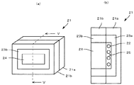
ここで算出される比誘電率は、ガラス溶解窯の側壁を構成する溶融鋳造耐火物13と同じ組成の溶融鋳造耐火物を用意して対照用溶融鋳造耐火物とし、この既知の厚さの対照用溶融鋳造耐火物の一方の面を測定するガラス溶解窯の炉内温度とほぼ同一の温度に加熱しておく。対照試験は、例えば、図5に示した試験炉21を用いて行う。ここで、図5(a)は試験炉21の斜視図、図5(b)は図5(a)のV−V断面図である。
The relative dielectric constant calculated here is prepared by preparing a molten cast refractory having the same composition as that of the molten cast refractory 13 constituting the side wall of the glass melting furnace to be a reference molten cast refractory. One surface of the molten cast refractory for heating is heated to substantially the same temperature as the furnace temperature of the glass melting furnace for measuring. The control test is performed using, for example, the
試験炉21は、その内部にヒータ22及び断熱材23aを有する(加熱側)試験炉21aと、その中央に断熱材23bを介して対照用溶融鋳造耐火物24を固定できる(耐火物固定側)試験炉21bと、から構成されている。そして、ヒータ22の加熱温度は、近傍に設けられた熱電対25により温度を検知して、所定の温度に炉内を加熱できるように制御されている。
The
この試験炉21を用いれば、既知の厚さの対照用溶融鋳造耐火物24の片面をヒータ22により実窯内温度と同等の温度に加熱し、対照用溶融鋳造耐火物24の加熱状態を実窯であるガラス溶解窯11の側壁と近似した加熱状態とできる。このときの加熱温度は、測定するガラス溶解窯の窯内温度に合わせて行うものであり、その温度は、窯内温度に対して±150℃の範囲をいい、±50℃の範囲であることが好ましい。また、実窯において、窯外面を冷却している場合には、試験炉においても同等の条件で冷却を行うことで、対照用溶融鋳造耐火物と実窯の溶融鋳造耐火物の温度分布を可能な限り近似した状態とするようにする。
When this
そして、試験炉21で対照用溶融鋳造耐火物24を十分に加熱した後、対照用溶融鋳造耐火物24の加熱される面の他方の面(試験炉21の炉外面)から、溶融鋳造耐火物の残厚測定装置1を用いて、対照用溶融鋳造耐火物24に向かってパルス状電磁波の送信を行う。それと同時に、送信した電磁波の対照用溶融鋳造耐火物24からの反射波データを取得する。すなわち、断熱板2を対照用溶融鋳造耐火物24にあてがい、断熱板2を介して電磁波探査機3により、対照用溶融鋳造耐火物24に対してパルス状電磁波の送受信を行って反射波データを取得する。
Then, after sufficiently heating the control molten cast refractory 24 in the
得られた反射波データから、電磁波の送信から対照用溶融鋳造耐火物24の加熱される側の面(試験炉の炉内面)からの反射波ピークが特定できる。この反射波ピークから、電磁波の送信から反射波の受信までの時間差(伝播時間)がわかり、このときの対照用溶融鋳造耐火物24と断熱板2とを合わせた材質、厚さについての見かけの比誘電率εpを次式により求めることができる。
From the obtained reflected wave data, the reflected wave peak from the surface to be heated of the control molten cast refractory 24 (the inner surface of the test furnace) can be identified from the transmission of electromagnetic waves. From this reflected wave peak, the time difference (propagation time) from the transmission of the electromagnetic wave to the reception of the reflected wave can be found, and the apparent material and thickness of the combined molten cast refractory 24 for control and the
電磁波探査機3による対照用溶融鋳造耐火物の厚さDは、対照用溶融鋳造耐火物中の電磁波の速度Vと対照用溶融鋳造耐火物に対して送信した電磁波の送信時刻から反射波の受信時刻までの時間差Tから(数1)により求めることができる。
The thickness D of the reference molten cast refractory by the
![]()
![]()

上記対照試験では、Dは対照用溶融鋳造耐火物24と断熱板2を合わせた厚さであって既知の値であり、Tは電磁波探査機3により測定される値であって、測定用電磁波の送信から反射波の受信までの時間差をそのまま用いる。また、Cは上記の通り定数である。したがって、上記対照試験を行うことにより、加熱状態における対照用溶融鋳造耐火物と断熱板をあわせた、見かけの比誘電率εpを算出できる。
In the above-mentioned control test, D is the thickness obtained by combining the control molten cast refractory 24 and the
なお、対照用溶融鋳造耐火物24としては、実窯であるガラス溶解窯11に用いられている溶融鋳造耐火物13の侵食された状況と合わせることで、より測定の精度が向上するため、溶融鋳造耐火物から切り出したものが好ましい。これは、溶融鋳造により得られた耐火物は、完全に均一な組成、組織でないことが一般的であり、溶融後、鋳型に流し込まれ冷却凝固される際に、場所により冷却速度が異なる等の理由により結晶サイズ、組成などの違いが生じるためである。
In addition, as the melt-cast refractory 24 for control, since the accuracy of measurement is further improved by combining with the eroded situation of the melt-cast refractory 13 used in the
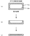
図6(a)に示したように、例えば、溶融鋳造により得られた溶融鋳造耐火物は、製造の際に、その表層付近は冷却速度が速くなり結晶サイズが小さく、濃度も内部とは若干異なる急冷部分13aとして形成される。また、その内部は表層付近とは異なり、徐々に冷却されていき結晶サイズが大きく、濃度も高くなりやすい徐冷部分13bとして形成される。そして、これがそのままガラス溶解窯11の側壁として使用される。
As shown in FIG. 6 (a), for example, in the case of a molten cast refractory obtained by melt casting, in the vicinity of the surface layer, the cooling rate is high, the crystal size is small, and the concentration is slightly different from the inside. It is formed as a
つまり、これを実窯に適用した場合には、最初は図6(a)のような断面で操業が開始されるが、操業を継続していくことで、溶融ガラスと接触するガラス溶解窯側が徐々に溶融鋳造耐火物が侵食され図6(b)のように薄くなり、さらには、図6(c)のようにさらに侵食が進んでいく。 In other words, when this is applied to an actual kiln, the operation is initially started with a cross section as shown in FIG. 6 (a), but by continuing the operation, the side of the glass melting kiln in contact with the molten glass is changed. The molten cast refractory is gradually eroded and thinned as shown in FIG. 6B, and further erosion proceeds as shown in FIG. 6C.
すなわち、本発明において測定対象となる溶融鋳造耐火物13は、図6(b)や図6(c)のように薄くなった状態であるため、より正確な測定を行うためには、一旦、図6(a)に示した操業前の溶融鋳造耐火物13と同じ厚さとなるように成形し、ここから侵食状況を想定して図6(b)や図6(c)のような一側面を切り出し、対照用溶融鋳造耐火物として用いることが好ましい。このように、実窯の耐火物配置時に使用された部位を考慮し、それと同等部位、配置状況で試験を実施することで、さらに測定誤差を小さくすることができる。 That is, since the molten cast refractory 13 to be measured in the present invention is in a thin state as shown in FIG. 6B or 6C, in order to perform more accurate measurement, It is formed so as to have the same thickness as the molten cast refractory 13 before operation shown in FIG. 6 (a), and one side as shown in FIG. 6 (b) and FIG. Is preferably used as a control melt cast refractory. In this way, the measurement error can be further reduced by considering the part used at the time of arranging the refractory in the actual kiln and conducting the test in the same part and the arrangement condition.
次に、実窯である溶解窯の側壁である溶融鋳造耐火物の残厚の測定を行う(S2)。 Next, the remaining thickness of the molten cast refractory that is the side wall of the melting kiln that is a real kiln is measured (S2).
図3は、図2のガラス溶解窯11の破線部分Aの部分拡大断面図である。図3に示したように、測定対象である溶融鋳造耐火物13の被測定面に断熱板2の一面を接触させ、電磁波探査機3をその断熱板2上に当接させながら、水平方向(図3で言えば、前後方向)に走査する。この水平方向の走査において、電磁波探査機3の位置は、ガラス溶解窯内の溶融ガラス12の界面の高さであることが好ましい。これは、溶融ガラスの界面において、溶解窯の側壁が侵食され易く、他の箇所に比べて厚さが薄くなるため、溶解窯の停止等の判断を行うのに適しているからである。
3 is a partially enlarged cross-sectional view of a broken line portion A of the
そして、この走査によって、電磁波探査機3の送信機32は送信アンテナ31から所定の電磁波を被測定面である溶融鋳造耐火物13に向かって連続的に送信し、それと同時に、該電磁波の溶融鋳造耐火物13からの反射波を受信アンテナ33で受信し、その受信状態を受信機34によって検知して、電磁波の反射波データを取得する。
Then, by this scanning, the
次に、得られた反射波データに基づいて、溶融鋳造耐火物の窯内周面からの反射波ピークの位置を判定する(S3)。この反射波ピークは、通常、一番大きな波形として表れ、また溶融鋳造耐火物とガラス素地の比誘電率の大小関係より、溶融鋳造耐火物→ガラス素地界面での反射率は、正の値となるため、反射波の位相を考慮すれば、容易に判定できる。 Next, the position of the reflected wave peak from the inner peripheral surface of the molten cast refractory is determined based on the obtained reflected wave data (S3). This reflected wave peak usually appears as the largest waveform, and the reflectivity at the interface between the molten cast refractory and the glass substrate is a positive value due to the relative dielectric constant between the molten cast refractory and the glass substrate. Therefore, it can be easily determined by considering the phase of the reflected wave.
そして、窯内周面からの反射波ピークの位置が判定できたら、その位置における反射波の測定時間から断熱板込みの溶融鋳造耐火物の厚さを算出する(S4)。具体的には、電磁波の送信時刻から反射波ピークの測定時刻の時間差が電磁波の伝播時間であるため、これを上記(数1)のTに当てはめると、対照試験でVは算出できているから、厚さDを算出できる。ただし、ここで算出される厚さは、溶融鋳造耐火物13と断熱板2とを合わせた厚さである。
And if the position of the reflected wave peak from a kiln internal peripheral surface can be determined, the thickness of the fusion | melting cast refractory material including a heat insulation board will be calculated from the measurement time of the reflected wave in the position (S4). Specifically, since the time difference between the transmission time of the electromagnetic wave and the measurement time of the reflected wave peak is the propagation time of the electromagnetic wave, if this is applied to T in (Equation 1), V can be calculated in the control test. The thickness D can be calculated. However, the thickness calculated here is the combined thickness of the molten cast refractory 13 and the
次に、溶融鋳造耐火物13単独の厚さを算出する(S5)。これは、上記S4で断熱板込みの厚さが既に算出されており、断熱板2の厚さは既知であるから、上記算出された厚さから実際に用いた断熱板2の厚さを差し引くことで、溶融鋳造耐火物13単独の残厚を算出できる。
Next, the thickness of the molten cast refractory 13 alone is calculated (S5). This is because the thickness including the heat insulating plate has already been calculated in S4, and the thickness of the
このS1〜S5のステップを、電磁波探査機3の水平方向への走査により複数個所で連続的に測定を行って、各測定箇所において、同じステップによりそれぞれの厚さを算出できる。これにより、ガラス溶解窯11の窯内周面の状態を把握できる。
The steps of S1 to S5 can be continuously measured at a plurality of locations by scanning the
なお、上記方法では、S4とS5の各ステップにより溶融鋳造耐火物13の残厚を算出しているが、S4において、断熱板2と溶融鋳造耐火物13の界面における反射波ピークの位置を完全に特定できる場合は、その反射波ピークと溶融鋳造耐火物13の窯内周面の反射波ピークとの時間差が溶融鋳造耐火物13単独の厚さを電磁波が往復した伝播時間に相当するため、この時間差から溶融鋳造耐火物13の残厚を算出してもよい。
In the above method, the remaining thickness of the molten cast refractory 13 is calculated in steps S4 and S5. However, in S4, the position of the reflected wave peak at the interface between the
〔第2の実施形態〕
次に、本発明の第2の実施形態について説明する。
第2の実施形態は、対照試験による比誘電率を対照用溶融鋳造耐火物の厚さを変えて複数個算出しておき、得られた複数の比誘電率を適用した溶融鋳造耐火物の厚さをそれぞれ算出し、その算出した厚さの中で最も適したものを溶融鋳造耐火物の厚さとして決定する点で第1の実施形態とは異なる。
[Second Embodiment]
Next, a second embodiment of the present invention will be described.
In the second embodiment, a plurality of relative dielectric constants in the control test are calculated by changing the thickness of the molten cast refractory for control, and the thickness of the molten cast refractory to which the obtained multiple relative dielectric constants are applied. This is different from the first embodiment in that each thickness is calculated and the most suitable thickness among the calculated thicknesses is determined as the thickness of the molten cast refractory.
この実施形態のフローチャートを図7に示したが、S12〜14までは、第1の実施形態のS2〜S4と同一の操作を行う。また、S16はS5に対応するステップであり、同一の操作を行う。以下、相違点を中心に説明する。 Although the flowchart of this embodiment is shown in FIG. 7, the same operation as S2 to S4 of the first embodiment is performed from S12 to S14. S16 is a step corresponding to S5, and performs the same operation. Hereinafter, the difference will be mainly described.
この実施形態では、まず、第1の実施形態のS1と同様に対照試験で比誘電率を算出する(S11)。ただし、本実施形態では、次に説明するように比誘電率を複数個算出する。 In this embodiment, first, the relative dielectric constant is calculated in the control test as in S1 of the first embodiment (S11). However, in the present embodiment, a plurality of relative dielectric constants are calculated as described below.
これは、実窯の溶融鋳造耐火物の残厚がどの程度の厚さであるかがわからないため、対照試験において、複数の厚さの溶融鋳造耐火物について、それぞれの比誘電率を算出しておくものである。例えば、対照用溶融鋳造耐火物として、断熱板込みの対照用溶融鋳造耐火物の厚さ(Tα)として40mm、70mm、100mm、130mmのものについて、それぞれの比誘電率εp1、εp2、εp3、εp4を求めておく。 This is because it is not known how much the remaining thickness of the molten cast refractory in the actual kiln is, so in the control test, the relative permittivity of each of the molten cast refractories with multiple thicknesses is calculated. It is something to keep. For example, as the control molten cast refractory, the relative dielectric constants εp 1 , εp 2 , εp of the control molten cast refractories including the heat insulating plate having the thickness (Tα) of 40 mm, 70 mm, 100 mm, and 130 mm, respectively. 3 and εp 4 are obtained in advance.
実窯測定(S12)、実窯内周面ピーク位置判定(S13)、断熱板込みの厚さ算出(S14)は、それぞれS2〜S4に対応するステップで、同一の操作により行う。ただし、S14において用いる比誘電率は、S11で算出した複数の比誘電率全てを用い、それぞれの比誘電率を適用した時の厚さを求める。 The actual kiln measurement (S12), the actual kiln inner peripheral surface peak position determination (S13), and the thickness calculation including the heat insulating plate (S14) are performed by the same operation in steps corresponding to S2 to S4, respectively. However, the relative dielectric constant used in S14 uses all of the plurality of relative dielectric constants calculated in S11, and obtains the thickness when each relative dielectric constant is applied.
そして、本実施形態においては、S14で算出された断熱板込みの溶融鋳造耐火物の換算厚み(Tβ)について、いずれの数値が最も妥当であるか判定を行う(S15)。ここでは、それぞれの計算に用いた比誘電率の基になる断熱板込みの対照用溶融鋳造耐火物の厚さ(Tα)と算出された溶融鋳造耐火物の換算厚み(Tβ)からその絶対値|Tα−Tβ|を算出し、一番小さい値となったものを最適なものとして、これを耐火物込みの溶融鋳造耐火物の厚さとして決定する。 In the present embodiment, it is determined which numerical value is most appropriate for the converted thickness (Tβ) of the molten cast refractory including the heat insulating plate calculated in S14 (S15). Here, the absolute value is calculated from the thickness (Tα) of the reference molten cast refractory including the heat insulating plate and the calculated thickness (Tβ) of the molten cast refractory calculated as the basis of the relative dielectric constant used for each calculation. | Tα−Tβ | is calculated, and the smallest value is determined as the optimum value, and this is determined as the thickness of the molten cast refractory including the refractory.
なお、このとき絶対値が5.0mm以内となっていることが好ましく、それより大きくなっている場合には、誤差が大きいものとして、再度測定条件を変更する等により検討することが望ましい。 At this time, the absolute value is preferably within 5.0 mm, and if it is larger than that, it is desirable that the error be large and that the measurement conditions be changed again.
そして、溶融鋳造耐火物13単独の残厚を算出する(S16)。これは、第1の実施形態のS5に対応するステップであり、同一の操作により、S15で決定された断熱板込みの溶融鋳造耐火物13の換算厚みから断熱板の厚さを除くことで行えばよい。 Then, the remaining thickness of the molten cast refractory 13 alone is calculated (S16). This is a step corresponding to S5 of the first embodiment, and is performed by removing the thickness of the heat insulating plate from the converted thickness of the molten cast refractory 13 including the heat insulating plate determined in S15 by the same operation. Just do it.
本実施形態により、溶融鋳造耐火物の残厚について、より誤差の少ない測定ができ、ガラス溶解窯の操業の可否判断を最適化することが可能となる。 According to this embodiment, the remaining thickness of the molten cast refractory can be measured with less error, and it is possible to optimize the judgment of whether or not to operate the glass melting furnace.
以下、上記した第2の実施形態に基づいて、対照試験によって複数の厚みに対する比誘電率を求める場合の厚み算出例を以下に示す。ここでは2種類の比誘電率を用いる場合、例えば、断熱板込みの対照用溶融鋳造耐火物の厚さ(以下、Tαと称する。)が70mmと100mmの厚さのものを用いた場合を説明する。 Hereinafter, based on the above-described second embodiment, a thickness calculation example in the case where the relative permittivity for a plurality of thicknesses is obtained by a control test is shown below. Here, when two types of relative dielectric constants are used, for example, the case where the thickness of a reference molten cast refractory including a heat insulating plate (hereinafter referred to as Tα) is 70 mm and 100 mm is described. To do.
まず、それぞれの厚さの見かけの比誘電率εpを求める。このように厚みが変わった場合、断熱板と溶融鋳造耐火物の体積比の変化、窯の温度分布の変化等によりそれぞれ比誘電率が変化する。得られた結果を表1に示した。 First, the apparent relative dielectric constant εp of each thickness is obtained. When the thickness changes in this way, the relative dielectric constant changes due to changes in the volume ratio between the heat insulating plate and the molten cast refractory, changes in the temperature distribution of the kiln, and the like. The obtained results are shown in Table 1.
そして、実窯での測定による反射波データから、電磁波の送信から反射波の受信までの時間差から、上記で得られた比誘電率を用い、それぞれの換算厚みTβを算出する。このとき、TαとTβの差の絶対値も計算する。得られた差の絶対値を比較し、絶対値が最も小さいデータが妥当であると判断し、使用する換算厚みTβを決定する。この結果を表2に示した。 And each conversion thickness T (beta) is calculated from the reflected wave data by the measurement in a real kiln, and the relative permittivity obtained above from the time difference from transmission of an electromagnetic wave to reception of a reflected wave. At this time, the absolute value of the difference between Tα and Tβ is also calculated. The absolute values of the obtained differences are compared, it is determined that the data having the smallest absolute value is appropriate, and the converted thickness Tβ to be used is determined. The results are shown in Table 2.
ここでは、Tαが70mm厚のとき、絶対値は30.3mmであり、Tαが100mm厚のとき、絶対値は1.8mmであり、絶対値の小さい100mm厚の対照用溶融鋳造耐火物に基づく算出値が妥当であると判断する。最後に、この換算厚みTβから断熱板の厚みを引いて、溶融鋳造耐火物の残厚とする。 Here, when Tα is 70 mm thick, the absolute value is 30.3 mm, and when Tα is 100 mm thick, the absolute value is 1.8 mm, which is based on a 100 mm thick reference molten cast refractory with a small absolute value. Judge that the calculated value is appropriate. Finally, the thickness of the heat insulating plate is subtracted from the converted thickness Tβ to obtain the remaining thickness of the molten cast refractory.
なお、複数の比誘電率を用いる場合においても、上記の残厚決定の方法は一例であり、他の残厚の決定方法として、Tαに対するεpの変化が極値を持つ様な変化ではなく、単調増加または単調減少である限り、反復法などの数学的解法を用いても良いし、各厚みデータ間の値を線形補間等により内挿し用いてもよい。
少なくとも、実施例に示す溶融鋳造耐火物に関する限りTαに対するεpの変化が極値を持つような変化は観測されておらず、第2の実施形態により、溶融鋳造耐火物の残厚がどのような厚さであってもより精度高く測定することを可能とする。
Even when a plurality of relative dielectric constants are used, the above-described method for determining the remaining thickness is an example. As another method for determining the remaining thickness, a change in εp with respect to Tα is not a change that has an extreme value. As long as monotonous increase or monotonic decrease, a mathematical solution such as an iterative method may be used, or a value between thickness data may be interpolated by linear interpolation or the like.
At least as far as the molten cast refractories shown in the examples are concerned, no change is observed in which the change in εp with respect to Tα has an extreme value, and according to the second embodiment, what is the remaining thickness of the molten cast refractory? Even a thickness can be measured with higher accuracy.
なお、第2の実施形態によれば、溶融鋳造耐火物の残厚がどのような厚さであってもより精度高く測定できるが、ガラス溶解窯の使用限界を見極めるという点では、第1の実施形態において、対照用溶融鋳造耐火物を使用限界と同程度の厚さとして用いていれば、限界値における算出値は妥当であるため問題はない。 According to the second embodiment, the thickness of the molten cast refractory can be measured with higher accuracy regardless of the thickness, but in terms of determining the use limit of the glass melting furnace, the first In the embodiment, if the control molten cast refractory is used with a thickness similar to the use limit, there is no problem because the calculated value at the limit value is appropriate.
以下、本発明を実施例及び比較例によって具体的に説明するが、本発明はこれらの記載によってなんら限定されるものではない。 EXAMPLES Hereinafter, although an Example and a comparative example demonstrate this invention concretely, this invention is not limited at all by these description.
実施例に使用する溶融鋳造耐火物は、ジルコニア成分を約95%含む、ガラス溶解窯用の溶融鋳造耐火物(AGCセラミックス社製、商品名:ZB−X9510)である。比誘電率測定に使用した対照用の溶融鋳造耐火物の寸法は、400mm×200mm×60mm、一個の質量が約26kgである。 The melt-cast refractory used in the examples is a melt-cast refractory for glass melting kiln (trade name: ZB-X9510, manufactured by AGC Ceramics) containing about 95% zirconia component. The size of the control molten cast refractory used for the relative permittivity measurement is 400 mm × 200 mm × 60 mm, and the mass of one piece is about 26 kg.
試験炉としては、図5に示した比誘電率測定用の対照試験設備である試験炉を用いた。なお、炉外面に相当する低温部が外気に接触しているが、さらに、実際のガラス溶解窯と同様に、炉外面に対し強制空気冷却を行うことにより、炉内側の温度と、炉外側の温度をコントロールしている。 As the test furnace, the test furnace which is a control test facility for measuring the relative dielectric constant shown in FIG. 5 was used. Although the low temperature portion corresponding to the outer surface of the furnace is in contact with the outside air, the temperature inside the furnace and the temperature outside the furnace are further reduced by performing forced air cooling on the outer surface of the furnace as in the actual glass melting furnace. The temperature is controlled.
また、電磁波探査機としては、日本無線社製のレーダーNJJ−95A(商品名)を使用した。この装置には、メモリカードが設けられており、測定結果である反射波データが保存可能となっている。得られたデータは、外部のコンピューターで処理して、反射波ピーク位置の検出、溶融鋳造耐火物の残厚の算出を実施した。 As an electromagnetic wave probe, a radar NJJ-95A (trade name) manufactured by Japan Radio Co., Ltd. was used. This apparatus is provided with a memory card, and can store reflected wave data as a measurement result. The obtained data was processed by an external computer to detect the reflected wave peak position and calculate the remaining thickness of the molten cast refractory.
図5の試験炉を用い、厚み60mmの対照用の溶融鋳造耐火物を片面加熱炉に固定した状態で、試験炉内温度を測定すべきガラス溶解窯の窯内温度と同じ1500℃に加熱し、外面は強制空気冷却を実施したところ溶融鋳造耐火物の炉外面温度は、480℃となった。 Using the test furnace shown in FIG. 5, with the 60-mm-thick control molten cast refractory fixed to a single-sided heating furnace, the test furnace temperature was heated to 1500 ° C., the same as the furnace temperature of the glass melting furnace to be measured. When the outer surface was subjected to forced air cooling, the furnace outer surface temperature of the molten cast refractory was 480 ° C.
この状態で、炉外側の対照用溶融鋳造耐火物の表面に、170mm×300mm×15mm厚のベニア板;温度拡散率:3.6×10⁻⁷m2/sec、比誘電率:2.2、発火温度:400℃)を接触させ、このベニア板の温度が上昇する前に、素早く電磁波探査機をベニア板の表面に接触させ測定した。なお、ここで、ベニア板の温度拡散率は、ベニア板の密度500〔kg/m3〕、熱伝導率0.18〔W/(m・K)〕、比熱1000〔J/kg/K〕として計算した。 In this state, on the surface of the control molten cast refractory outside the furnace, a veneer plate having a thickness of 170 mm × 300 mm × 15 mm; temperature diffusivity: 3.6 × 10 −7 m 2 / sec, relative dielectric constant: 2.2 , Ignition temperature: 400 ° C.), and before the temperature of the veneer plate rose, the electromagnetic wave probe was quickly brought into contact with the surface of the veneer plate and measured. Here, the temperature diffusivity of the veneer plate is the density of the veneer plate 500 [kg / m 3 ], the thermal conductivity 0.18 [W / (m · K)], and the specific heat 1000 [J / kg / K]. As calculated.
上記の通り参照実験炉の炉外面温度が480℃であるが、これはベニア板の発火温度400℃を超えている。しかし実際に測定は5秒以内で終了するため測定自体は問題なく実施できた。しかしベニア板の端部が焦げてしまうなどの現象が見られ、実施例2に後述する、より耐熱性に優れる断熱板を用いる方が望ましい。 As described above, the outer surface temperature of the reference experimental furnace is 480 ° C., which exceeds the ignition temperature of the veneer plate of 400 ° C. However, since the measurement actually ended within 5 seconds, the measurement itself could be carried out without any problem. However, a phenomenon such as scorching of the end of the veneer plate is observed, and it is desirable to use a heat insulating plate with higher heat resistance, which will be described later in Example 2.
この測定では、電磁波探査機により中心周波数が0.9GHzの電磁波を、断熱板を介して対照用の溶融鋳造耐火物に向かって送信し、その電磁波の溶融鋳造耐火物からの反射波を受信して反射波データを得た。電磁波探査機の電磁波の送信したときの反射波データは、送信してからの時間経過と反射波の波形との関係を示す画像データとして得られる。得られた反射波データに対して、その反射波のピーク位置(伝播時間)と対照用溶融鋳造耐火物及び断熱材の厚さとから(数1)及び(数2)を用いて、断熱板を含んだ見かけの比誘電率を算出したところ、εp=15.7となった。なお、見かけの比誘電率εpを15.7としたときの、反射波ピークと断熱板込みの対照用溶融鋳造耐火物の換算厚みとの関係について図8に示した。破線が反射波ピークの位置であり、以下の反射波データにおいても同様である。 In this measurement, an electromagnetic wave probe transmits an electromagnetic wave having a center frequency of 0.9 GHz to a reference molten cast refractory through a heat insulating plate, and receives a reflected wave of the electromagnetic wave from the molten cast refractory. The reflected wave data was obtained. The reflected wave data when the electromagnetic wave of the electromagnetic wave probe is transmitted is obtained as image data indicating the relationship between the time elapsed since the transmission and the waveform of the reflected wave. For the obtained reflected wave data, using the (Equation 1) and (Equation 2) from the peak position (propagation time) of the reflected wave and the thickness of the molten cast refractory for control and the heat insulating material, The apparent dielectric constant included was calculated to be εp = 15.7. FIG. 8 shows the relationship between the reflected wave peak and the converted thickness of the control molten cast refractory including the heat insulating plate when the apparent relative dielectric constant εp is 15.7. The broken line is the position of the reflected wave peak, and the same applies to the reflected wave data below.
まず、この実施例を元に、溶融鋳造耐火物の温度が上昇した際に、溶融鋳造耐火物内部の電磁波の減衰が大きくなることについて説明する。図8の高温での対照試験と同様の測定を常温にて行った結果を図9に示す。図9の反射波ピークは非常に大きくはっきりしているが、図8の反射波ピークは非常に小さい。これは、前述したとおり、高温になると溶融鋳造耐火物内での電磁波の減衰が増加するためである。例えば、常温から1500℃まで温度を上げていく途中において段階的に同様の測定を行うと、図9の反射波ピークが徐々に小さくなり、図8に近づいていき、図8のピークは間違いなく背面反射波ピークであることがわかっている。 First, based on this example, it will be described that the attenuation of electromagnetic waves inside the molten cast refractory increases when the temperature of the molten cast refractory rises. FIG. 9 shows the results of measurements similar to those in the high temperature control test of FIG. 8 performed at room temperature. Although the reflected wave peak in FIG. 9 is very large and clear, the reflected wave peak in FIG. 8 is very small. This is because, as described above, the attenuation of electromagnetic waves in the molten cast refractory increases at a high temperature. For example, if the same measurement is performed step by step in the course of raising the temperature from room temperature to 1500 ° C., the reflected wave peak in FIG. 9 gradually decreases and approaches FIG. 8, and the peak in FIG. It is known that it is a back reflection wave peak.
しかし、断熱板の比誘電率がさらに小さくなり、溶融鋳造耐火物との界面反射が増加したり、さらに煉瓦厚みが厚くなって煉瓦内部での電磁波減衰が増えた場合などは、さらに背面における反射波ピークが小さくなってしまい、ピークが検出できない可能性がある。このため電磁波をできるだけ効率的に被測定対象である溶融鋳造耐火物に送り込むことが重要であり、前述した範囲の比誘電率を有する断熱板を用いる必要がある。 However, if the dielectric constant of the heat insulating plate is further reduced, the interface reflection with the molten cast refractory is increased, or if the brick thickness is increased and the electromagnetic wave attenuation inside the brick is increased, the reflection on the back surface is further increased. There is a possibility that the wave peak becomes small and the peak cannot be detected. For this reason, it is important to send electromagnetic waves as efficiently as possible to the molten cast refractory to be measured, and it is necessary to use a heat insulating plate having a relative dielectric constant in the range described above.
また、この実施例を元に、溶融鋳造耐火物の比誘電率が温度によって変化することについて説明する。図9の常温の結果より、断熱板を含んだ見かけの比誘電率を算出したところεp=9.8となった。図8の高温の場合は、εp=15.7であったので温度が上昇したことにより比誘電率の値が全く異なる値となることがわかる。このため、実窯での残厚測定のためには、実窯状態に近い高温条件での比誘電率を把握しておかなければ誤差の少ない測定はできない。 Moreover, it demonstrates that the dielectric constant of a molten cast refractory changes with temperature based on this Example. From the result at room temperature in FIG. 9, the apparent dielectric constant including the heat insulating plate was calculated, and εp = 9.8. In the case of the high temperature shown in FIG. 8, since εp = 15.7, it can be seen that the value of the relative dielectric constant becomes completely different as the temperature rises. For this reason, in order to measure the remaining thickness in an actual kiln, measurement with little error cannot be performed unless the relative permittivity is measured under high temperature conditions close to the actual kiln state.
次に、実際に操業している板ガラスの窯末期停止直前に、測定した。このガラス溶解窯については図3に示したように、側壁である溶融鋳造耐火物13の溶融ガラス12の液面の高さにおいて測定した。この実窯測定により得られた反射波データについて、対照試験のεp=15.7を適用することで、反射波ピークの測定時間(伝播時間)から断熱板込みの換算厚みを算出した。その結果を図10に示した。
Next, the measurement was performed immediately before the end of the kiln of the plate glass actually operated. About this glass melting furnace, as shown in FIG. 3, it measured in the height of the liquid level of the
この結果から、板ガラス窯の測定箇所の残厚は、72mm(ピーク位置)−15mm(断熱板厚さ)=57mmと測定された。この測定実施から数日以内に窯が停止され、冷却された後に窯内に入って測定実施部位の残厚を確認したところ、60mmであり電磁波による測定結果と実際の厚みの誤差は+3mmであった。上記のように本発明を用いることで、少なくとも50mm以上の厚さの溶融鋳造耐火物の熱間使用時における残厚を高い精度(例えば、±5.0mm程度)で測定できるため、窯の停止、修理実施の判断を適切に行うことができる。 From this result, the remaining thickness of the measurement location of the plate glass kiln was measured as 72 mm (peak position) −15 mm (heat insulating plate thickness) = 57 mm. The kiln was stopped within a few days after the measurement was performed, and after entering the kiln, the remaining thickness of the measurement site was confirmed. As a result, the error between the measurement result due to electromagnetic waves and the actual thickness was +3 mm. It was. By using the present invention as described above, since the remaining thickness of the molten cast refractory having a thickness of at least 50 mm or more during hot use can be measured with high accuracy (for example, about ± 5.0 mm), the kiln is stopped. Therefore, it is possible to make an appropriate decision on repair execution.
実施例2では、実施例1と、ほぼ同じ条件で対照試験を実施した。実施例1との違いは、溶融鋳造耐火物の厚みと断熱板の種類である。溶融鋳造耐火物の厚みとして90mmのものを使用した。サイズは400mm×200mm×90mm、一個の質量が約39kgである。また、実施例2では、実施例1に述べた断熱板の耐熱性の問題や、電磁波を効率よく溶融鋳造耐火物に送る点を改良するために、より耐熱性が高くかつ比誘電率が大きい次の断熱板を使用した。 In Example 2, a control test was performed under substantially the same conditions as in Example 1. The difference from Example 1 is the thickness of the molten cast refractory and the type of heat insulating plate. The thickness of the molten cast refractory was 90 mm. The size is 400 mm × 200 mm × 90 mm, and the mass of one piece is about 39 kg. Moreover, in Example 2, in order to improve the heat resistance problem of the heat insulating plate described in Example 1 and the point of efficiently sending electromagnetic waves to the molten cast refractory, the heat resistance is higher and the relative dielectric constant is higher. The following insulation board was used.
ガラス繊維含有セメント板(ニチアス社製、商品名:ヘミサル15:温度拡散率が3.6×10⁻⁷m2/sec、比誘電率が12.0、耐熱温度が 500℃)
使用したサイズは、170mm×450mm×10mm厚。
Glass fiber-containing cement board (manufactured by NICHIAS, trade name: Hemisal 15: temperature diffusivity is 3.6 × 10 −7 m 2 / sec, relative permittivity is 12.0, heat resistance is 500 ° C.)
The size used is 170mm x 450mm x 10mm thick.
実施例1と同様に、炉内温度を1500℃に加熱し、外面を強制空気冷却を実施したところ、溶融鋳造耐火物の炉外面温度は、408℃となった。
さらに実施例1と同様の方法で、断熱板を含んだ見かけの比誘電率を算出したところεp=17.4となった。なお、見かけの比誘電率εpを17.4としたときの、反射波ピークと断熱板込みの対照用溶融鋳造耐火物の換算厚みとの関係について図11に示した。
As in Example 1, when the furnace temperature was heated to 1500 ° C. and forced air cooling was performed on the outer surface, the furnace outer surface temperature of the molten cast refractory was 408 ° C.
Further, when the apparent relative dielectric constant including the heat insulating plate was calculated in the same manner as in Example 1, εp = 17.4 was obtained. FIG. 11 shows the relationship between the reflected wave peak and the converted thickness of the control molten cast refractory including the heat insulating plate when the apparent relative dielectric constant εp is 17.4.
次に、実際に操業している板ガラス窯において、測定を実施した。このガラス溶解窯については図3に示したように、側壁である溶融鋳造耐火物13の溶融ガラス12の液面の高さにおいて、電磁波探査機を水平方向に走査し連続的に測定した。断熱板の位置を変えた測定を合計3回実施した。断熱材の位置を変える際に、前回測定との重複部分が存在する様にし、またその変位代を把握しておき、これらの測定結果をコンピューター上でつなぎ合わせた。その結果、溶融鋳造耐火物の目地をはさんだ、長手方向約700mmにわたる反射波ピークを連続的に捉えた。この実窯測定により得られた反射波データについて、対照試験のεp=17.4を適用することで、反射波ピークの測定時間(伝播時間)から断熱板込みの換算厚みを算出した。
Next, measurement was carried out in a plate glass kiln that was actually operated. As shown in FIG. 3, the glass melting furnace was continuously measured by scanning the electromagnetic wave probe in the horizontal direction at the height of the liquid surface of the
この換算厚みについて、走査したときの複数の測定地点全てで算出し、得られた換算厚みから断熱板の厚さを引いて、それぞれの溶融鋳造耐火物の残厚を算出した。得られた溶融鋳造耐火物の残厚について、これを走査した水平方向の距離を横軸に、溶融鋳造耐火物の残厚を縦軸にとって、図12に示した。なお、横軸は水平方向の距離を表わすが、溶融鋳造耐火物の目地を0点として表わした。 About this conversion thickness, it calculated in all the several measurement points when it scanned, and subtracted the thickness of the heat insulation board from the obtained conversion thickness, and calculated the remaining thickness of each molten cast refractory. The remaining thickness of the obtained molten cast refractory is shown in FIG. 12 with the horizontal distance obtained by scanning the horizontal axis being the horizontal axis and the remaining thickness of the molten cast refractory being the vertical axis. The horizontal axis represents the distance in the horizontal direction, but the joint of the molten cast refractory is represented as 0 point.
この結果から、溶融鋳造耐火物の残厚は、目地付近の最も薄い部分で90mmとなっている。実際の厚みは操業中であることから、目地からの物差挿入による測定値のみであり少なくとも70mm以上であることはわかっているが、絶対値の確認はできなかった。 From this result, the remaining thickness of the molten cast refractory is 90 mm in the thinnest part near the joint. Since the actual thickness is in operation, it is known that it is only a measured value by inserting a difference from the joint and is at least 70 mm or more, but the absolute value could not be confirmed.
一方、場所による相対的な厚みの変化について、溶融鋳造耐火物が目地に向けて薄くなっている様子が測定されている。通常のガラス溶解窯を停止した際の観察において、水平方向の厚み分布については、目地部分の残厚が他の部分の残厚よりも薄くなることが一般的であり、操業中においても同様の厚み分布であることが推察できる。 On the other hand, it has been measured that the molten cast refractory is becoming thinner toward the joints with respect to the relative thickness change depending on the location. In the observation when the normal glass melting furnace is stopped, the horizontal thickness distribution is generally that the remaining thickness of the joint part is thinner than the remaining thickness of the other part, and the same during operation It can be inferred that this is a thickness distribution.
また右側の煉瓦に比べて左側の煉瓦の方が、残厚が少ない測定結果であるが、実際の炉でも左側の煉瓦の方が、煉瓦に接している溶融ガラスの温度が高い事が確認されており、左の煉瓦の方が浸食が早く進むことは容易に推察できる。以上のことから、場所による残厚の相対的な変化について、本測定結果が妥当性であることが確認された。上記のように、場所による浸食量の違いが把握できることは、素地漏れの可能性が高い場所を特定できることにつながり、ガラス素地漏れ事故防止の観点で極めて有用な情報となる。 In addition, the left brick has a smaller residual thickness than the right brick, but it is confirmed that the temperature of the molten glass in contact with the brick is higher in the left brick even in an actual furnace. It can be easily guessed that erosion proceeds faster with the left brick. From the above, it was confirmed that this measurement result is valid for the relative change of the remaining thickness depending on the location. As described above, being able to grasp the difference in the amount of erosion depending on the location leads to identification of a location with a high possibility of substrate leakage, which is extremely useful information from the viewpoint of preventing glass substrate leakage accidents.
上記のように、本発明を用いることで、少なくとも50mm以上の厚さの溶融鋳造耐火物の熱間使用時における残厚を高い精度(例えば、±5.0mm程度)で測定でき、また残厚が薄くなっている部分を探し出せるため、炉の停止、修理実施の判断を適切に行うことができる。 As described above, by using the present invention, the remaining thickness of a molten cast refractory having a thickness of at least 50 mm or more during hot use can be measured with high accuracy (for example, about ± 5.0 mm). Because it is possible to find the thinned part, it is possible to appropriately judge whether to stop the furnace or to repair it.
本発明は、高温状態における溶融鋳造耐火物の厚さを測定するのに有効な測定方法及び測定装置であり、さらに、経時的に厚さが変化する溶融鋳造耐火物の残厚測定に極めて有効である。 The present invention is a measuring method and measuring apparatus effective for measuring the thickness of a molten cast refractory in a high temperature state, and is extremely effective for measuring the remaining thickness of a molten cast refractory whose thickness changes over time. It is.
1…溶融鋳造耐火物の残厚測定装置、2…断熱板、3…電磁波探査機、31…送信アンテナ、32…送信機、33…受信アンテナ、34…受信機、11…ガラス溶解窯、12…溶融ガラス、13…溶融鋳造耐火物
DESCRIPTION OF
Claims (8)
前記パルス状電磁波の前記対照用溶融鋳造耐火物の前記加熱される側の面からの反射波データを取得して前記対照用溶融鋳造耐火物の見かけの比誘電率を求める工程と、
前記ガラス溶解窯の測定すべき溶融鋳造耐火物の外周面に、耐熱温度が250℃以上、比誘電率が2以上20以下、温度拡散率が2×10⁻⁶m2/sec以下の断熱板を接触させ、前記断熱板を介して前記対照用溶融鋳造耐火物に送信したパルス状電磁波と同一周波数の電磁波を前記測定すべき溶融鋳造耐火物に向かって送信する工程と、
前記パルス状電磁波の前記溶融鋳造耐火物の炉内周面からの反射波データを取得する工程と、
前記パルス状電磁波の反射波データから求めた前記パルス状電磁波の前記溶融鋳造耐火物内の伝播時間と、前記対照用溶融鋳造耐火物について求めた見かけの比誘電率から前記溶融鋳造耐火物の残厚を算出する工程と、
を有することを特徴とする溶融鋳造耐火物の残厚測定方法。 A method for measuring a remaining thickness of a molten cast refractory used on a side wall of a glass melting furnace, wherein one side of a reference molten cast refractory having the same composition as the molten cast refractory to be measured is melted into the glass While heating to a temperature almost the same as the temperature in the kiln of the kiln, the other surface of the reference molten cast refractory has a heat-resistant temperature of 250 ° C. or higher, a relative dielectric constant of 2 to 20, and a temperature diffusivity of 2 ×. A step of contacting a heat insulating plate of 10 −6 m 2 / sec or less and transmitting a pulsed electromagnetic wave having a center frequency of 0.5 to 3 GHz toward the control molten cast refractory through the heat insulating plate;
Obtaining reflected wave data from the heated side surface of the reference molten cast refractory of the pulsed electromagnetic wave to determine an apparent relative dielectric constant of the reference molten cast refractory;
On the outer peripheral surface of the molten cast refractory to be measured in the glass melting kiln, a heat insulating plate having a heat resistance temperature of 250 ° C. or higher, a relative dielectric constant of 2 or more and 20 or less, and a temperature diffusivity of 2 × 10 −6 m 2 / sec or less. And transmitting an electromagnetic wave having the same frequency as the pulsed electromagnetic wave transmitted to the control molten cast refractory through the heat insulating plate toward the molten cast refractory to be measured,
Obtaining reflected wave data from the inner peripheral surface of the molten cast refractory of the pulsed electromagnetic wave;
Based on the propagation time of the pulsed electromagnetic wave in the molten cast refractory obtained from the reflected wave data of the pulsed electromagnetic wave, and the apparent relative dielectric constant obtained for the reference molten cast refractory, the remaining molten cast refractory is determined. Calculating the thickness;
A method for measuring a remaining thickness of a molten cast refractory, comprising:
前記溶融鋳造耐火物の残厚を算出する工程において、複数個それぞれの見かけの比誘電率を適用して前記溶融鋳造耐火物の残厚をそれぞれ算出し、
得られた複数の溶融鋳造耐火物の残厚について、用いた比誘電率の算出の基礎となった対照用溶融鋳造耐火物の厚さとの差が最も小さいものを残厚として決定する請求項1記載の溶融鋳造耐火物の残厚測定方法。 In the control test, a plurality of apparent relative dielectric constants were obtained using a plurality of control melt cast refractories having different thicknesses,
In the step of calculating the remaining thickness of the molten cast refractory, the remaining thickness of the molten cast refractory is calculated by applying a plurality of apparent relative dielectric constants, respectively.
The remaining thickness of the plurality of obtained molten cast refractories is determined as the remaining thickness with the smallest difference from the thickness of the reference molten cast refractory used as the basis for calculating the relative dielectric constant used. The method for measuring the remaining thickness of the molten cast refractory as described.
前記断熱板を介してパルス状電磁波を前記溶融鋳造耐火物の外周面に向かって送信アンテナから送信させる送信機と、該パルス状電磁波の前記溶融鋳造耐火物からの反射波を受信アンテナで受信して反射波データを取得する受信機と、を有する電磁波探査機と、
から構成されることを特徴とする溶融鋳造耐火物の残厚測定装置。 When measuring the remaining thickness of the molten cast refractory used for the side wall of the glass melting furnace, the heat resistance temperature is 250 ° C. or higher, the relative dielectric constant is 2 or higher, and 20 or lower, the temperature diffusion. A heat insulating plate having a rate of 2 × 10 −6 m 2 / sec or less,
A transmitter for transmitting a pulsed electromagnetic wave from the transmitting antenna toward the outer peripheral surface of the molten cast refractory through the heat insulating plate, and a reflected wave of the pulsed electromagnetic wave from the molten cast refractory is received by the receiving antenna. An electromagnetic wave probe having a receiver for acquiring reflected wave data,
An apparatus for measuring the remaining thickness of a molten cast refractory, comprising:
前記電磁波探査機により前記溶融鋳造耐火物から得られた反射波データに対し、前記記憶手段に格納されている比誘電率を適用して溶融鋳造耐火物の残厚を測定する演算手段と、
を有する請求項5記載の溶融鋳造耐火物の残厚測定装置。 In the measurement of the remaining thickness of the molten cast refractory, storage means for storing the relationship between the thickness of the reference molten cast refractory and the relative dielectric constant;
A calculation means for measuring the remaining thickness of the molten cast refractory by applying a relative dielectric constant stored in the storage means for the reflected wave data obtained from the molten cast refractory by the electromagnetic wave probe,
The apparatus for measuring a residual thickness of a molten cast refractory according to claim 5.
Priority Applications (1)
| Application Number | Priority Date | Filing Date | Title |
|---|---|---|---|
| JP2010149659A JP5395000B2 (en) | 2010-06-30 | 2010-06-30 | Method and apparatus for measuring remaining thickness of molten cast refractory |
Applications Claiming Priority (1)
| Application Number | Priority Date | Filing Date | Title |
|---|---|---|---|
| JP2010149659A JP5395000B2 (en) | 2010-06-30 | 2010-06-30 | Method and apparatus for measuring remaining thickness of molten cast refractory |
Publications (2)
| Publication Number | Publication Date |
|---|---|
| JP2012013512A JP2012013512A (en) | 2012-01-19 |
| JP5395000B2 true JP5395000B2 (en) | 2014-01-22 |
Family
ID=45600132
Family Applications (1)
| Application Number | Title | Priority Date | Filing Date |
|---|---|---|---|
| JP2010149659A Active JP5395000B2 (en) | 2010-06-30 | 2010-06-30 | Method and apparatus for measuring remaining thickness of molten cast refractory |
Country Status (1)
| Country | Link |
|---|---|
| JP (1) | JP5395000B2 (en) |
Families Citing this family (6)
| Publication number | Priority date | Publication date | Assignee | Title |
|---|---|---|---|---|
| JP5659838B2 (en) * | 2011-02-09 | 2015-01-28 | Jfeスチール株式会社 | Brick thickness measurement method |
| JP2014190901A (en) * | 2013-03-28 | 2014-10-06 | Ube Ind Ltd | Firebrick abnormality detector |
| US9880110B2 (en) | 2014-03-26 | 2018-01-30 | Paneratech, Inc. | Material erosion monitoring system and method |
| US9488601B2 (en) * | 2014-03-26 | 2016-11-08 | Paneratech, Inc. | Material erosion monitoring system and method |
| CN111854668B (en) * | 2020-08-25 | 2024-07-12 | 中冶赛迪工程技术股份有限公司 | Blast furnace lining thickness calculating device and method based on distributed optical fiber temperature measurement |
| JP7803234B2 (en) * | 2022-09-09 | 2026-01-21 | Agc株式会社 | Remaining thickness measuring device, remaining thickness measuring method, and glass manufacturing method |
Family Cites Families (2)
| Publication number | Priority date | Publication date | Assignee | Title |
|---|---|---|---|---|
| JP2663220B2 (en) * | 1992-01-17 | 1997-10-15 | 日本無線 株式会社 | Thickness measuring device |
| JP2003294430A (en) * | 2002-04-01 | 2003-10-15 | Mitsubishi Heavy Ind Ltd | Measuring instrument for thickness of refractory |
-
2010
- 2010-06-30 JP JP2010149659A patent/JP5395000B2/en active Active
Also Published As
| Publication number | Publication date |
|---|---|
| JP2012013512A (en) | 2012-01-19 |
Similar Documents
| Publication | Publication Date | Title |
|---|---|---|
| JP5395000B2 (en) | Method and apparatus for measuring remaining thickness of molten cast refractory | |
| CN107820565B (en) | Equipment for determining and/or monitoring the temperature of a medium | |
| Prasad et al. | Viscosity measurements of melts at high temperatures using ultrasonic guided waves | |
| EP3368910B1 (en) | Life optimization and monitoring system of the lining of an industrial furnace | |
| US8876372B2 (en) | Sensor arrangement for temperature measurement and method for measurement | |
| US6296385B1 (en) | Apparatus and method for high temperature viscosity and temperature measurements | |
| TW200907319A (en) | Structural component based on a ceramic body | |
| Dos Santos | Thermal properties of melt polymers by the hot wire technique | |
| CN112534226A (en) | Temperature measuring device and method for determining a temperature | |
| US20010033599A1 (en) | Thermocouple-type temperature-detecting device | |
| JP4264301B2 (en) | Diagnostic method for temperature sensor, refractory and refractory lining | |
| JP5064433B2 (en) | Method, apparatus and program for estimating heat flux on inner surface of container | |
| CA2590298A1 (en) | Thermocouple assembly and method of use | |
| JP5574142B2 (en) | Cooling liquid management apparatus and method, and temperature measuring element | |
| KR20250140562A (en) | Refractory monitoring system for high-voltage and high-temperature environment applications | |
| JP4843790B2 (en) | Temperature measurement method using ultrasonic waves | |
| JP2007033077A (en) | Method and apparatus for measuring temperature of mold material surface, and evaluation method and apparatus for mold release agent | |
| US20240093983A1 (en) | System and method for determining the thickness of a material in manufacturing vessels | |
| JP2021533343A (en) | Glass furnace with optical fiber | |
| KR20180066261A (en) | Determining the length of the electrode in the melting furnace | |
| KR100348064B1 (en) | Method for selecting optimal drilling position of tap hole on bottom of blast furnace | |
| JP2020059610A (en) | Method for evaluating peeling resistance of alumina-magnesia quality castable refractory | |
| CN106312032B (en) | Online ladle residual thick marker method safely | |
| JPH10273708A (en) | Estimation method of blast furnace bottom condition | |
| Zhu et al. | Effect of multilayered coating of single-mode optical fibers on distributed temperature and strain measurement in mortar specimens |
Legal Events
| Date | Code | Title | Description |
|---|---|---|---|
| A621 | Written request for application examination |
Free format text: JAPANESE INTERMEDIATE CODE: A621 Effective date: 20130510 |
|
| A977 | Report on retrieval |
Free format text: JAPANESE INTERMEDIATE CODE: A971007 Effective date: 20130913 |
|
| TRDD | Decision of grant or rejection written | ||
| A01 | Written decision to grant a patent or to grant a registration (utility model) |
Free format text: JAPANESE INTERMEDIATE CODE: A01 Effective date: 20131015 |
|
| A61 | First payment of annual fees (during grant procedure) |
Free format text: JAPANESE INTERMEDIATE CODE: A61 Effective date: 20131017 |
|
| R150 | Certificate of patent or registration of utility model |
Ref document number: 5395000 Country of ref document: JP Free format text: JAPANESE INTERMEDIATE CODE: R150 Free format text: JAPANESE INTERMEDIATE CODE: R150 |
|
| R250 | Receipt of annual fees |
Free format text: JAPANESE INTERMEDIATE CODE: R250 |
|
| R250 | Receipt of annual fees |
Free format text: JAPANESE INTERMEDIATE CODE: R250 |
|
| R250 | Receipt of annual fees |
Free format text: JAPANESE INTERMEDIATE CODE: R250 |
|
| R250 | Receipt of annual fees |
Free format text: JAPANESE INTERMEDIATE CODE: R250 |
|
| R250 | Receipt of annual fees |
Free format text: JAPANESE INTERMEDIATE CODE: R250 |
|
| R250 | Receipt of annual fees |
Free format text: JAPANESE INTERMEDIATE CODE: R250 |
|
| R250 | Receipt of annual fees |
Free format text: JAPANESE INTERMEDIATE CODE: R250 |
|
| R250 | Receipt of annual fees |
Free format text: JAPANESE INTERMEDIATE CODE: R250 |