JP5437654B2 - Temperature measuring device - Google Patents
Temperature measuring device Download PDFInfo
- Publication number
- JP5437654B2 JP5437654B2 JP2009023822A JP2009023822A JP5437654B2 JP 5437654 B2 JP5437654 B2 JP 5437654B2 JP 2009023822 A JP2009023822 A JP 2009023822A JP 2009023822 A JP2009023822 A JP 2009023822A JP 5437654 B2 JP5437654 B2 JP 5437654B2
- Authority
- JP
- Japan
- Prior art keywords
- value
- temperature
- sensor unit
- voltage value
- measured voltage
- Prior art date
- Legal status (The legal status is an assumption and is not a legal conclusion. Google has not performed a legal analysis and makes no representation as to the accuracy of the status listed.)
- Expired - Fee Related
Links
Images


Landscapes
- Measuring Temperature Or Quantity Of Heat (AREA)
Description
本発明は、白金測温抵抗体、サーミスタなど、温度によりその抵抗値が変化する素子をセンサとして利用して、測定した抵抗値から温度値を算出する温度測定装置に関するものである。 The present invention relates to a temperature measuring device that calculates a temperature value from a measured resistance value by using, as a sensor, an element whose resistance value varies depending on temperature, such as a platinum resistance thermometer or a thermistor.
従来から白金測温抵抗体、サーミスタなど、温度の変化に応じてその抵抗値が変化する素子を用いた温度測定装置が利用されている。 Conventionally, temperature measuring devices using elements such as platinum resistance thermometers, thermistors, etc. whose resistance values change according to changes in temperature have been used.
この種の従来の温度測定装置としては、例えば図4に示すものがある。この装置においては、白金測温抵抗体をセンサとして使用している。白金測温抵抗体は、温度によって抵抗値が変化するものであり、その抵抗値特性、すなわち温度値に対する抵抗値の対応関係はJIS C 1604規格書で規格化されている。尚、一般にPt100(0°Cのときの抵抗値が100Ω)のものが使用される。 An example of such a conventional temperature measuring apparatus is shown in FIG. In this apparatus, a platinum resistance thermometer is used as a sensor. The resistance value of the platinum resistance thermometer varies with temperature, and the resistance value characteristic, that is, the correspondence relationship of the resistance value to the temperature value is standardized in the JIS C 1604 standard. In general, Pt100 (resistance value at 0 ° C. is 100Ω) is used.
また、この白金測温抵抗体に定電流を供給したときの白金測温抵抗体の両端間の電圧値と抵抗値とは比例関係にあることから、当該白金測温抵抗体に所定の定電流を供給して得られる電圧値から、白金測温抵抗体における温度値が算出される(又は、前記定電流値と電圧値とから白金測温抵抗体の抵抗値を求め、さらに当該抵抗値と前記温度値に対する抵抗値の対応関係を参照して、当該白金測温抵抗体における温度値が算出される)。 In addition, since a voltage value and a resistance value between both ends of the platinum resistance thermometer when a constant current is supplied to the platinum resistance thermometer are in a proportional relationship, a predetermined constant current is supplied to the platinum resistance thermometer. The temperature value in the platinum resistance thermometer is calculated from the voltage value obtained by supplying (or the resistance value of the platinum resistance thermometer is obtained from the constant current value and the voltage value, and the resistance value and The temperature value in the platinum resistance thermometer is calculated with reference to the correspondence relationship of the resistance value to the temperature value).
この従来の装置では、定電流電源が白金測温抵抗体に定電流を供給し、当該抵抗体間に生じる電圧(電位差)を入力値としてADコンバータがこれを取得する。当該ADコンバータは、前記入力値をデジタル信号に変換し、マイコン(マイクロコンピュータ)に出力する。 In this conventional apparatus, a constant current power source supplies a constant current to a platinum resistance thermometer, and an AD converter acquires a voltage (potential difference) generated between the resistors as an input value. The AD converter converts the input value into a digital signal and outputs it to a microcomputer.
マイコンは、記憶手段と演算手段とを備えており、前記記憶手段には、前記規格書に基づきPt100の白金測温抵抗体に所定の定電流を供給したときに得られる当該白金測温抵抗体の両端間の電圧値と温度値との対応関係を示す関数式が格納されている(あるいは、前記電圧値に対応する温度値の対応関係がテーブル形式で格納されている)。前記演算手段は、白金測温抵抗体に所定の定電流を供給して得られた前記電圧値と前記関数式とを参照して、測定すべき温度値を算出する(あるいは、得られた前記電圧値と、前記テーブルとを参照して、測定すべき温度値を算出する)。尚、図4における白金測温抵抗体以外は、破線で示す基板上に設けられている。 The microcomputer includes storage means and calculation means, and the platinum resistance thermometer obtained when a predetermined constant current is supplied to the platinum resistance thermometer of Pt100 based on the standard document. Is stored (or a correspondence relationship between the temperature values corresponding to the voltage values is stored in a table format). The calculation means calculates a temperature value to be measured with reference to the voltage value obtained by supplying a predetermined constant current to the platinum resistance thermometer and the function equation (or the obtained temperature value). The temperature value to be measured is calculated with reference to the voltage value and the table). In addition, except the platinum resistance thermometer in FIG. 4, it is provided on the board | substrate shown with a broken line.
このような温度測定装置においては、センサ(白金測温抵抗体)の測定確度が高くても、基板とセンサとを接続するリード線の抵抗のため、測定誤差が生じるという問題があった。 In such a temperature measuring device, there is a problem that even if the measurement accuracy of the sensor (platinum resistance temperature detector) is high, a measurement error occurs due to the resistance of the lead wire connecting the substrate and the sensor.
そこで、ブリッジ回路を利用した所謂3導線式や、電流印加用のリード線と電圧計測用のリード線とを分離した所謂4導線式などを用いることによって、前記リード線の抵抗による測定誤差をなくすような対策が取られてきた(例えば、特許文献1、非特許文献1参照)。 Therefore, by using a so-called three-conductor type using a bridge circuit or a so-called four-conductor type in which a lead wire for current application and a lead wire for voltage measurement are separated, a measurement error due to the resistance of the lead wire is eliminated. Such measures have been taken (see, for example, Patent Document 1 and Non-Patent Document 1).
しかしながら、このように改善された温度測定装置においても、実際には基板上の配線パターンや、ノイズを除去するためのフィルタ回路、測定電圧値を増幅するアンプ装置における抵抗などによりわずかな測定誤差を生じていた。しかも、この誤差は基板1枚毎に微妙に違っている。それゆえ、基板の製造工程において基板1枚毎に手作業でアンプ装置の増幅度を微調整してマイコンへ出力される測定電圧値を、前記関数式、あるいはテーブルとを正確に一致させるためのキャリブレーション(補正)を行う必要があった。 However, even in the temperature measuring apparatus improved in this way, a slight measurement error is actually caused by the wiring pattern on the substrate, the filter circuit for removing noise, the resistance in the amplifier apparatus for amplifying the measured voltage value, and the like. It was happening. In addition, this error is slightly different for each substrate. Therefore, in the manufacturing process of the substrate, it is possible to finely adjust the amplification degree of the amplifier device manually for each substrate and accurately match the measured voltage value output to the microcomputer with the function equation or the table. It was necessary to perform calibration (correction).
また、キャリブレーションを行って前記アンプ装置の増幅度を調整した基板も、運搬中の接触や振動により、調整が狂ってしまうという問題があった。さらに、例えば、温度測定装置を道路近傍などの自然環境下に設置すると、風や振動などの影響により、経時的に前記キャリブレーションの調整が狂ってしまって、正確な温度測定が出来なくなるという問題点があった。 In addition, the substrate that has been calibrated to adjust the amplification degree of the amplifier device has a problem that the adjustment is out of order due to contact and vibration during transportation. Furthermore, for example, if the temperature measuring device is installed in a natural environment such as near a road, the calibration adjustment will be over time due to the influence of wind and vibration, and accurate temperature measurement will not be possible. There was a point.
そこで、本発明は、上記のような問題点を克服するためになされたものであり、手作業で基盤1枚毎にキャリブレーションを行う必要がなく製造が容易で、かつ運送中や設置後における振動等の影響による前記キャリブレーションの狂いを考慮しなくてよい温度測定装置を提供することを目的とする。また、それにより簡易な構成で安定的に確度の高い温度測定が可能な温度測定装置を提供することを目的とする。 Therefore, the present invention has been made to overcome the above-mentioned problems, and it is not necessary to perform calibration for each board manually, and is easy to manufacture, and in transit or after installation. It is an object of the present invention to provide a temperature measurement device that does not need to consider the calibration error due to the influence of vibration or the like. It is another object of the present invention to provide a temperature measuring apparatus capable of stably measuring temperature with high accuracy with a simple configuration.
上記の目的を達成するため、本発明に係る温度測定装置は、温度変化に応じて抵抗値が比例的に変化する抵抗素子からなるセンサ部に定電流を供給して得られる該センサ部の両端間の電圧値から、前記センサ部における温度値を算出して出力する温度測定装置であって、
前記センサ部が所定温度において有する抵抗値と同じ抵抗値を有し、温度変化によっても抵抗値が一定の基準抵抗体を前記センサ部に並列して配し、
定電流を前記基準抵抗体に流して得られた該基準抵抗体の両端間の測定電圧値から、測定電圧値と温度値との対応関係を求め、
該対応関係に基づいて、センサ部に定電流を供給して得られる該センサ部の両端間の測定電圧値から、センサ部における温度値を算出するようになされ、
且つ、前記センサ部として白金測温抵抗体が使用され、
前記基準抵抗体として、前記白金測温抵抗体の0℃における抵抗値と同じ抵抗値の基準抵抗体と、0℃を超える温度における抵抗値と同じ抵抗値の基準抵抗体と、0℃未満の温度における抵抗値と同じ抵抗値の基準抵抗体とを含む3つ以上の異なる抵抗値の前記基準抵抗体が、それぞれ前記センサ部と並列に配されて、
前記3つ以上の基準抵抗体についての前記測定電圧値と温度値との対応関係が、0℃以上の温度値において用いる関数式と、0℃以下の温度値において用いる関数式とでそれぞれ表されるとともに、
該関数式に基づいて、前記センサ部に定電流を供給して得られる該センサ部の両端間の測定電圧値から、前記センサ部における温度値を算出するようにしたことを特徴とする。
In order to achieve the above object, a temperature measuring device according to the present invention provides both ends of a sensor unit obtained by supplying a constant current to a sensor unit composed of a resistance element whose resistance value changes in proportion to a temperature change. A temperature measuring device that calculates and outputs a temperature value in the sensor unit from a voltage value between,
The sensor unit has the same resistance value as the resistance value at a predetermined temperature, and a reference resistor having a constant resistance value due to a temperature change is arranged in parallel with the sensor unit,
From the measured voltage value between both ends of the reference resistor obtained by flowing a constant current through the reference resistor, the correspondence between the measured voltage value and the temperature value is obtained,
Based on the correspondence, a temperature value in the sensor unit is calculated from a measured voltage value between both ends of the sensor unit obtained by supplying a constant current to the sensor unit ,
And a platinum resistance thermometer is used as the sensor part,
As the reference resistor, a reference resistor having the same resistance value as that of the platinum resistance thermometer at 0 ° C., a reference resistor having the same resistance value as that at a temperature exceeding 0 ° C., and less than 0 ° C. The reference resistors having three or more different resistance values including a reference resistor having the same resistance value as the resistance value at the temperature are respectively arranged in parallel with the sensor unit,
The correspondence relationship between the measured voltage value and the temperature value for the three or more reference resistors is expressed by a function equation used at a temperature value of 0 ° C. or higher and a function equation used at a temperature value of 0 ° C. or lower, respectively. And
A temperature value in the sensor unit is calculated from a measured voltage value between both ends of the sensor unit obtained by supplying a constant current to the sensor unit based on the function formula .
ここで、センサ部としては、温度と抵抗値とが比例的に変化する素子を利用するのが、好ましい。例えば、JIS C 1604規格書で規格化されている白金測温抵抗体(Pt100)や、特定の温度範囲内で温度と抵抗値とが比例的に変化するPTCタイプのサーミスタなどを好適に利用できる。 Here, as the sensor unit, it is preferable to use an element in which the temperature and the resistance value change proportionally. For example, a platinum resistance thermometer (Pt100) standardized in the JIS C 1604 standard or a PTC type thermistor in which the temperature and the resistance value change proportionally within a specific temperature range can be suitably used. .
また、基準抵抗体は、温度変化に関わらずその抵抗値が変化しない素子であれば、どのようなものであってもよい。例えば、金属薄膜により形成される高精度抵抗体が使用できる。好ましくは、温度係数(温度が1℃上昇したときの抵抗値の変化割合)が±1〜±25ppm/℃のものを使用すれば、より精度の高い温度測定が可能となる。 The reference resistor may be any element as long as its resistance value does not change regardless of temperature change. For example, a high precision resistor formed of a metal thin film can be used. Preferably, temperature measurement with higher accuracy is possible by using a temperature coefficient (change rate of resistance value when the temperature rises by 1 ° C.) of ± 1 to ± 25 ppm / ° C.
本発明の温度測定装置によれば、センサ部が所定温度において有する抵抗値と同じ抵抗値を有し、かつ温度変化によっても抵抗値が一定の基準抵抗体を利用し、当該基準抵抗体に定電流を供給して実際に電圧値を測定する。この測定電圧値は、基準抵抗体以外の配線パターンやフィルタ回路等の抵抗による影響も含んだ電圧値であり、この得られた測定電圧値と前記所定温度値との対応関係を求める。この対応関係を所定温度におけるセンサ部に定電流を供給して得られる測定電圧値と温度値との関係とし、この対応関係に基づいて、センサ部に定電流を供給して得られる該センサ部の両端間の測定電圧値から、センサ部における温度値を算出する。すなわち、基準抵抗体を利用し、各基板の配線パターンやフィルタ回路その他の素子の抵抗による影響を含んで実際に得られた測定電圧値から、測定電圧値と温度値との対応関係を求める。したがって、配線パターン等の抵抗による誤差を考慮する必要がなく、またキャリブレーションを行う必要もない。 According to the temperature measuring apparatus of the present invention, a reference resistor having the same resistance value as the resistance value of the sensor unit at a predetermined temperature and having a constant resistance value due to a temperature change is used. Supply current and actually measure voltage. This measured voltage value is a voltage value including the influence of resistances such as a wiring pattern other than the reference resistor and a filter circuit, and a correspondence relationship between the obtained measured voltage value and the predetermined temperature value is obtained. This correspondence is defined as a relationship between a measured voltage value obtained by supplying a constant current to the sensor unit at a predetermined temperature and a temperature value, and based on this correspondence, the sensor unit obtained by supplying a constant current to the sensor unit The temperature value in the sensor unit is calculated from the measured voltage value between both ends of the sensor. That is, using the reference resistor, the correspondence between the measured voltage value and the temperature value is obtained from the actually measured voltage value including the influence of the resistance of the wiring pattern of each substrate, the filter circuit, and other elements. Therefore, it is not necessary to consider an error due to resistance such as a wiring pattern, and it is not necessary to perform calibration.
よって、製造が容易で、かつ運送中などにおける前記キャリブレーションの狂いを考慮する必要がなく、かつ簡易な構成で安定的に確度の高い温度測定が可能となる。 Therefore, manufacturing is easy, and it is not necessary to consider the calibration error during transportation, and temperature measurement with high accuracy can be stably performed with a simple configuration.
また、本発明に係る温度測定装置においては、異なる抵抗値を有する複数の前記基準抵抗体をそれぞれ前記センサ部と並列に配し、前記複数の基準抵抗体について求められた各々の前記測定電圧値と温度値との対応関係を満たすような前記測定電圧値と温度値との対応関係を示す関数式を作成し、該関数式に基づいて、前記センサ部に定電流を供給して得られる該センサ部の両端間の測定電圧値から、前記センサ部における温度値を算出するようにするのが好ましい。 Further, in the temperature measurement device according to the present invention, a plurality of the reference resistors having different resistance values are arranged in parallel with the sensor unit, and the measured voltage values obtained for the plurality of reference resistors are obtained. A function equation indicating the correspondence relationship between the measured voltage value and the temperature value that satisfies the correspondence relationship between the temperature value and the measured voltage value is created, and the constant current is supplied to the sensor unit based on the function equation. It is preferable to calculate a temperature value in the sensor unit from a measured voltage value between both ends of the sensor unit.
このようにすれば、測定電圧値と温度値の対応関係が複数得られ、それらの対応関係を満たす関数式を作成することで、当該関数式に基づいて、センサ部に定電流を供給して得られる測定電圧値から、容易にセンサ部における温度値が算出される。 In this way, multiple correspondences between the measured voltage value and the temperature value are obtained, and by creating a function equation that satisfies these correspondences, a constant current is supplied to the sensor unit based on the function equation. The temperature value in the sensor unit is easily calculated from the measured voltage value obtained.
この点、例えば上述の白金測温抵抗体(Pt100)を利用すれば、温度変化と抵抗値(および電圧値)の変化との関係が直線性(比例的関係)を示すことから、互いに抵抗値が異なる2つの基準抵抗体を利用し、それぞれの測定電圧値と温度値との対応関係を求め、それら2つの対応関係を満たす一次関数を作成してもよい。 For example, if the platinum resistance thermometer (Pt100) described above is used, the relationship between the change in temperature and the change in resistance value (and voltage value) exhibits linearity (proportional relationship). Two reference resistors having different values may be used, the corresponding relationship between the measured voltage value and the temperature value may be obtained, and a linear function satisfying the two corresponding relationships may be created.
すなわち、定電流を供給して得られる電圧値と温度値との関係が直線性を示す抵抗素子をセンサとして利用することにより、測定電圧値と温度値との関係が一次関数式V=αt+β[Vは測定電圧値(mV)、αは温度が1℃上昇したときの測定電圧値の変化の割合(温度係数)、tは温度(℃)、βは0℃における測定電圧値]で示される。そして、互いに抵抗値が異なる2つの基準抵抗体を利用してそれぞれの測定電圧値と温度値との対応関係を求め、上記関数式において前記対応関係を満たすα、およびβを求めて関数式を作成する。これにより作成された前記関数式に基づいて、センサ部に定電流を供給して得られる該センサ部の両端間の測定電圧値から、前記センサ部における温度値を算出することができる。 That is, by using, as a sensor, a resistance element in which the relationship between the voltage value obtained by supplying a constant current and the temperature value is linear, the relationship between the measured voltage value and the temperature value is expressed by a linear function equation V = αt + β [ V is a measured voltage value (mV), α is a change rate (temperature coefficient) of the measured voltage value when the temperature is increased by 1 ° C., t is a temperature (° C.), β is a measured voltage value at 0 ° C. . Then, using two reference resistors having mutually different resistance values, the corresponding relationship between the measured voltage value and the temperature value is obtained, and α and β satisfying the corresponding relationship in the above functional equation are obtained and the functional equation is obtained. create. Based on the function formula thus created, the temperature value in the sensor unit can be calculated from the measured voltage value across the sensor unit obtained by supplying a constant current to the sensor unit.
また、3つ以上の前記基準抵抗体をそれぞれ前記センサ部と並列に配して、それぞれの測定電圧値と温度値との対応関係を求め、それら対応関係を満たす関数式を作成する。基準抵抗を多く配するほど実測値に近い関数式を導くことが可能となるので、より確度の高い温度測定が可能となる。 Further, by arranging three or more of the reference resistor in parallel with each of the sensor unit, it obtains a correspondence between the respective measured voltage value and the temperature value, to create a functional expression satisfying their correspondence. As more reference resistors are arranged, a function expression closer to the actual measurement value can be derived, and therefore temperature measurement with higher accuracy can be performed.
また、本発明に係る温度測定装置は、温度変化に応じて抵抗値が比例的に変化する抵抗素子からなるセンサ部と、
前記センサ部に定電流を供給する定電流電源と、
前記センサ部の両端間の電圧値を入力値とし、該入力値を増幅して出力するアンプ装置と、
前記アンプ装置から出力した測定電圧値をデジタル信号に変換するADコンバータと、
前記センサ部に定電流を流して得られる該センサ部の両端間の前記測定電圧値とそれに対応する温度値との対応関係を示す関数式又は対応関係データを格納する記憶手段と、
前記ADコンバータから出力された測定電圧値と前記関数式又は対応関係データとを参照して、温度値を算出する演算手段とを備える温度測定装置であって、
前記センサ部として白金測温抵抗体が使用され、
前記センサ部が所定温度において有する抵抗値と同じ抵抗値を有し、温度変化によっても抵抗値が一定の基準抵抗体であって、各々前記センサ部と並列に接続された、前記白金測温抵抗体の0℃における抵抗値と同じ抵抗値の基準抵抗体と、0℃を超える温度における抵抗値と同じ抵抗値の基準抵抗体と、0℃未満の温度における抵抗値と同じ抵抗値の基準抵抗体とを含む3つ以上の異なる抵抗値の基準抵抗体と、
前記センサ部及び前記各基準抵抗体のうちのいずれか一つに前記定電流電源からの定電流を供給するように接続を切り替える切替手段と、
前記切替手段により、前記各基準抵抗体それぞれに定電流を供給して得られた各基準抵抗体の両端間における測定電圧値を前記センサ部の各所定温度における測定電圧値として判断する判断手段と、
前記判断手段において判断した測定電圧値と温度値との対応関係を満たす関数式又は対応関係データを作成する対応関係作成手段とを備え、該対応関係作成手段において0℃以上の温度値において用いる関数式又は対応関係データと、0℃以下の温度値において用いる関数式又は対応関係データとがそれぞれ作成されると共に、前記演算手段において、センサ部に定電流を供給して得られる該センサ部の両端間の測定電圧値と前記関数式又は対応関係データとを参照して温度値を算出するようにしたことを特徴とする。
In addition, the temperature measuring device according to the present invention includes a sensor unit composed of a resistance element whose resistance value changes in proportion to a temperature change,
A constant current power source for supplying a constant current to the sensor unit;
The voltage value between both ends of the sensor unit as an input value, an amplifier device that amplifies and outputs the input value;
An AD converter that converts a measured voltage value output from the amplifier device into a digital signal;
Storage means for storing a functional expression or correspondence data indicating a correspondence relationship between the measured voltage value between both ends of the sensor portion obtained by flowing a constant current through the sensor portion and a temperature value corresponding thereto;
A temperature measurement apparatus comprising a calculation means for calculating a temperature value with reference to the measurement voltage value output from the AD converter and the functional expression or correspondence data,
A platinum resistance thermometer is used as the sensor unit,
The platinum resistance thermometer having a resistance value that is the same as the resistance value that the sensor unit has at a predetermined temperature, and a resistance value that is constant even with a temperature change, each connected in parallel with the sensor unit. A reference resistor having the same resistance value as the resistance value at 0 ° C., a reference resistor having the same resistance value as that at a temperature exceeding 0 ° C., and a reference resistor having the same resistance value as that at a temperature below 0 ° C. A reference resistor of three or more different resistance values including a body,
Switching means for switching connection so as to supply a constant current from the constant current power source to any one of the sensor unit and each of the reference resistors;
By the switching unit, a determination unit operable to determine a measured voltage value between both ends of the reference resistor body obtained by supplying a constant current to each of the reference resistors as a voltage value measured at each predetermined temperature of the sensor unit ,
A function formula that satisfies the correspondence relationship between the measured voltage value and the temperature value determined by the determination unit or a correspondence relationship creation unit that creates correspondence data, and the function used at a temperature value of 0 ° C. or higher in the correspondence relationship creation unit. Formulas or correspondence data and function formulas or correspondence data used at a temperature value of 0 ° C. or less are respectively created , and both ends of the sensor unit obtained by supplying a constant current to the sensor unit in the calculation unit The temperature value is calculated with reference to the measured voltage value and the functional expression or the correspondence data.
本願発明に係る温度測定装置によれば、複数の基準抵抗体を利用した実測値に基づいて測定電圧値とそれに対応する温度値との対応関係を示す関数式又は対応関係データを作成し、当該関数式又は対応関係データに基づいて、センサ部における測定電圧値から温度値を算出する。したがって、基板1枚毎にキャリブレーションを行う必要がなく、また運送中に生じるキャリブレーションの狂いを考慮しなくてよい。尚、ここで前記対応関係データとは、前記測定電圧値と温度値との関係をテーブル形式で表すものである。 According to the temperature measurement device according to the present invention, a function equation or correspondence data indicating a correspondence relationship between a measured voltage value and a corresponding temperature value is created based on an actual measurement value using a plurality of reference resistors, The temperature value is calculated from the measured voltage value in the sensor unit based on the functional equation or the correspondence data. Therefore, it is not necessary to perform calibration for each substrate, and it is not necessary to consider the calibration error that occurs during transportation. Here, the correspondence relationship data represents the relationship between the measured voltage value and the temperature value in a table format.
さらに、本発明に係る温度測定装置においては、通電開始時に測定電圧値と温度値との対応関係を示す関数式又は対応関係データの作成を開始する対応関係作成開始手段を備えるようにしてもよい。すなわち、本発明に係る温度測定装置に通電を開始すると、対応関係作成開始手段からのコマンドにより、前記切替手段が前記複数の基準抵抗体の一つずつに順に定電流を供給するよう接続を切り替え、各基準抵抗体の両端間における電圧値が測定され、該測定電圧値と温度値(所定温度)との対応関係を示す関数式又は対応関係データが作成される。 Furthermore, the temperature measurement device according to the present invention may further include correspondence creation start means for starting creation of a functional expression or correspondence data indicating the correspondence between the measured voltage value and the temperature value at the start of energization. . That is, when energization of the temperature measuring device according to the present invention is started, the connection is switched so that the switching unit sequentially supplies a constant current to each of the plurality of reference resistors by a command from the correspondence creation start unit. The voltage value between both ends of each reference resistor is measured, and a functional expression or correspondence data indicating the correspondence between the measured voltage value and the temperature value (predetermined temperature) is created.
このようにすると、本発明の温度測定装置に通電を開始すれば、自動的に測定電圧値と温度値との対応関係を示す関数式又は対応関係データが作成され、該関数式又は対応関係データに基づいて、前記測定電圧値から温度値を求めることが可能となる。したがって、製造工程や検査工程においてキャリブレーションを行わなくとも、温度測定装置に通電を開始するだけで、確度の高い温度測定ができる。また、定期的に当該温度測定装置の電源を入れ直すだけで、或いはマイコンを再起動するだけで、その都度前記関数式又は対応関係データが作成され、該関数式又は対応関係データに基づいて温度値を算出するので、当該温度測定装置を設置した後も、風や振動などによるキャリブレーション調整の狂いを手作業で補正する必要がない。 In this way, when energization of the temperature measuring device of the present invention is started, a function equation or correspondence data indicating the correspondence between the measured voltage value and the temperature value is automatically created, and the function equation or correspondence data On the basis of the measured voltage value, the temperature value can be obtained. Therefore, even if calibration is not performed in the manufacturing process or the inspection process, temperature measurement with high accuracy can be performed only by starting energization of the temperature measurement device. In addition, the function formula or correspondence data is created each time the power is periodically turned on or the microcomputer is restarted, and the temperature value is based on the function formula or the correspondence data. Therefore, even after the temperature measuring device is installed, it is not necessary to manually correct the calibration adjustment error due to wind or vibration.
本願発明に係る温度測定装置によれば、上述のように基準抵抗体を利用し、実測値に基づいて測定電圧値とそれに対応する温度値とを関連付ける関数式又は対応関係データを作成し、当該関数式又は対応関係データに基づいて、センサ部における測定電圧値から温度値を算出できる。したがって、手作業で基盤1枚毎にキャリブレーションを行う必要がなく製造が容易で、かつ運送中や設置後における振動等による前記キャリブレーションの狂いを考慮しなくてよい。また、安定的に確度の高い温度測定が可能な温度測定装置を提供することが可能となる。 According to the temperature measuring device according to the present invention, using the reference resistor as described above, a function equation or correspondence data that associates the measured voltage value with the corresponding temperature value is created based on the actually measured value, and Based on the functional equation or the correspondence data, the temperature value can be calculated from the measured voltage value in the sensor unit. Therefore, it is not necessary to perform calibration for each substrate manually, and manufacturing is easy, and it is not necessary to consider the calibration error due to vibration during transportation or after installation. In addition, it is possible to provide a temperature measuring device capable of stably measuring temperature with high accuracy.
以下、本願発明を実施するための形態を、図面に基づいて詳細に説明する。 Hereinafter, embodiments for carrying out the present invention will be described in detail with reference to the drawings.
図1の回路図に示すとおり、この実施形態における温度測定装置は、センサ部2、該センサ部2と並列に接続される基準抵抗A、B、C、およびこれらに定電流を供給する定電流電源31を備えている。この実施形態においては、センサ部2として白金測温抵抗体(Pt100)を使用しており、このセンサ部2の一端が、定電流電源31に切替手段(リレー)32を介して接続されており、他端は基準電位に接続されている。
As shown in the circuit diagram of FIG. 1, the temperature measurement device in this embodiment includes a
前記3つの基準抵抗体A、B、Cは、同様にリレー32を介して接続されており、切替手段32の接続切り替えにより、センサ部2、基準抵抗体A、B、Cのいずれか一つに定電流が供給されるように構成されている。
The three reference resistors A, B, and C are similarly connected via a
基準抵抗体A、B、Cは、いずれも温度変化に関わらず抵抗値が一定であり、また、それぞれの抵抗値は異なっている。この基準抵抗体としては、例えば金属薄膜により形成される高精度抵抗体が使用される。この実施形態においては、温度係数(温度が1℃上昇したときの抵抗値の変化割合)が±1〜±25ppm/℃であって、抵抗値許容差が±0.02〜0.1%のもの(たとえば、株式会社フラット電子製角型金属薄膜チップ抵抗器 RFC−3D)を使用する。 The reference resistors A, B, and C all have constant resistance values regardless of temperature changes, and the resistance values thereof are different. As this reference resistor, for example, a high-precision resistor formed of a metal thin film is used. In this embodiment, the temperature coefficient (the change rate of the resistance value when the temperature increases by 1 ° C.) is ± 1 to ± 25 ppm / ° C., and the resistance tolerance is ± 0.02 to 0.1%. A thing (for example, flat electronic Co., Ltd. square metal thin film chip resistor RFC-3D) is used.
定電流を供給したときのセンサ部2、基準抵抗体A、基準抵抗体B、及び基準抵抗体Cのそれぞれの両端間(P1−P2間)の電圧値は、フィルタ回路33でノイズがカットされ、アンプ装置34で増幅されて、ADコンバータ35がこれを取得する。ADコンバータ35は、アナログ信号で取得した測定電圧値をデジタル信号に変換してマイコン4に出力する。尚、ADコンバータ35は、マイコン4の内部に備えるようにしてもよい。
Noise is cut by the
マイコン4は、記憶手段41、演算手段42、判断手段43、対応関係作成手段44、出力手段45、および対応関係作成開始手段46を備えている。記憶手段42には、ADコンバータ35から出力された測定電圧値と温度値との対応関係を示す関数式又は対応関係データが格納されている。
演算手段42は、ADコンバータ35から出力された測定電圧値と前記関数式又は対応関係データとを参照して温度値を算出するように構成されている。
ところで、測定電圧値と温度値との関係を示す前記関数式又は対応関係データは、以下のとおり作成される。
The
The calculation means 42 is configured to calculate a temperature value with reference to the measured voltage value output from the
By the way, the function expression or the correspondence data indicating the relationship between the measured voltage value and the temperature value is created as follows.
すなわち、温度測定装置1の電源をオンにし、定電流電源31が定電流を供給し始めると、対応関係作成開始手段44が切替手段32に接続切替コマンドを送信する。切替手段32は、回路の接続を選択的に切り替えることができるリレー装置で構成され、前記接続切替コマンドに従って、基準抵抗体A、基準抵抗体B、基準抵抗体Cと順に接続を切り替えた後、最後にセンサ部2に接続する。この間、基準抵抗体A、B、およびCのそれぞれの接続時におけるP1−P2間における電圧値は、フィルタ33を通りアンプ装置34で増幅されてADコンバータ35において取得される。
That is, when the temperature measuring device 1 is turned on and the constant current power supply 31 starts to supply a constant current, the correspondence creation start means 44 transmits a connection switching command to the switching means 32. The switching means 32 is composed of a relay device that can selectively switch circuit connections, and in accordance with the connection switching command, after switching the connection in order with the reference resistor A, the reference resistor B, and the reference resistor C, Finally, the
基準抵抗体A、B、およびCは、それぞれ異なる抵抗値を有しており、かつそれぞれが、センサ部2に使用する白金測温抵抗体(Pt100)の所定温度における抵抗値と同じ又は近似する抵抗値を有している。尚、前記所定温度における抵抗値は、JIS C 1604規格書で規格化されている抵抗値特性に基づくものである。この実施形態においては、基準抵抗体Aの抵抗値は50Ω(すなわち、白金測温抵抗体が約−125℃の時の抵抗値)、基準抵抗体Bの抵抗値は100Ω(すなわち、白金測温抵抗体が0℃の時の抵抗値)、そして基準抵抗体Cの抵抗値は150Ω(すなわち、白金測温抵抗体が約130℃の時の抵抗値)のものを使用している。
The reference resistors A, B, and C have different resistance values, and each is the same as or approximate to the resistance value at a predetermined temperature of the platinum resistance thermometer (Pt100) used for the
上述のとおり、これら基準抵抗体A、B、およびCに順に定電流を供給し、それぞれP1−P2間における電圧値を測定する。この実施形態においては、1mAの定電流を供給して前記電圧値を測定したところ、各基準抵抗体A、B、CについてADコンバータで取得した測定電圧値Va、Vb、及びVcは、それぞれ60mV、110mV、160mVであった。 As described above, a constant current is supplied to these reference resistors A, B, and C in order, and the voltage value between P1 and P2 is measured. In this embodiment, when the voltage value was measured by supplying a constant current of 1 mA, the measured voltage values Va, Vb, and Vc acquired by the AD converter for each of the reference resistors A, B, and C were 60 mV, respectively. 110 mV and 160 mV.
ここで、ADコンバータ35で取得された測定電圧値は、デジタル信号に変換されマイコン4に送信される。そして、マイコン4の判断手段43は、各基準抵抗体における前記測定電圧値とそれに対応する各所定温度との対応関係を、センサ部2に定電流を供給して得られる測定電圧値とセンサ部2における温度値との対応関係と判断する。すなわち、判断手段43は、センサ部2(白金測温抵抗体)に1mAの定電流を供給したときの測定電圧値が60mVである場合には、センサ部2の温度値が−125℃であると判断する。また、同様に測定電圧値が110mVである場合には0℃、測定電圧値が160mVである場合には130℃であると判断する。
Here, the measured voltage value acquired by the
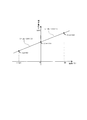
続いて、対応関係作成手段44は、上記測定電圧値と温度値との対応関係に基づき、当該対応関係を満たす関数式を作成する。尚、白金測温抵抗体(Pt100)は、0℃以上と0℃以下とで温度変化に対する抵抗値特性が異なることが知られており、また、−125℃〜0℃、および0℃〜130℃という温度域では、前記抵抗値特性が直線性を示すので、定電流を供給したときの測定電圧値と温度値との対応関係を一次関数式で表してもほとんど誤差がない。そこで、この実施形態においては、(1)−125℃〜0℃について、上記のとおり、測定電圧値が60mVのとき温度値は−125℃、測定電圧値が110mVのとき温度値は0℃という対応関係を満たす一次関数式を作成し、(2)0℃〜130℃について、測定電圧値が110mVのとき温度値は0℃、測定電圧値が160mVのとき温度値は130℃という対応関係を満たす一次関数式を作成する。 Subsequently, the correspondence creating means 44 creates a function expression that satisfies the correspondence based on the correspondence between the measured voltage value and the temperature value. The platinum resistance thermometer (Pt100) is known to have different resistance characteristics with respect to temperature changes between 0 ° C. and 0 ° C., and also from −125 ° C. to 0 ° C. and 0 ° C. to 130 ° C. In the temperature range of ° C., the resistance value characteristic exhibits linearity, so that there is almost no error even if the correspondence relationship between the measured voltage value and the temperature value when a constant current is supplied is expressed by a linear function equation. Therefore, in this embodiment, as described above, for (1) -125 ° C. to 0 ° C., the temperature value is −125 ° C. when the measured voltage value is 60 mV, and the temperature value is 0 ° C. when the measured voltage value is 110 mV. Create a linear function equation that satisfies the correspondence relationship. (2) For 0 ° C to 130 ° C, when the measured voltage value is 110 mV, the temperature value is 0 ° C, and when the measured voltage value is 160 mV, the temperature value is 130 ° C. Create a linear function that satisfies
すなわち、上述の一次関数式V=αt+β[Vは測定電圧値(mV)、αは温度が1℃上昇したときの測定電圧値の変化の割合(温度係数)、tは温度(℃)、βは0℃における測定電圧値]に前記各測定値(対応関係)を代入して計算すると、(1)−125℃〜0℃については、V=2t/5+110[Vは測定電圧値(mV)、tは温度値(℃)]の関数式が得られ、(2)0℃〜130℃については、V=5t/13+110の関数式が得られる。これをグラフに示すと図2のようになる。尚、上記各関数式は、記憶手段41に格納される。 That is, the above-mentioned linear function equation V = αt + β [V is the measured voltage value (mV), α is the rate of change in the measured voltage value when the temperature rises by 1 ° C. (temperature coefficient), t is the temperature (° C.), β Is calculated by substituting each measured value (corresponding relationship) into the measured voltage value at 0 ° C., and for (1) -125 ° C. to 0 ° C., V = 2t / 5 + 110 [V is the measured voltage value (mV) , T is a temperature equation (° C.)], and (2) for 0 ° C. to 130 ° C., a function equation of V = 5t / 13 + 110 is obtained. This is shown in a graph in FIG. Each function formula is stored in the storage means 41.
上記(1)(2)の式を変形して、(1)−125℃〜0℃については、t=2.5V−275、(2)0℃〜130℃については、t=2.6V−286の関数式がそれぞれ得られる。 By modifying the above formulas (1) and (2), (1) t = 2.5V-275 for -125 ° C to 0 ° C, (2) t = 2.6V for 0 ° C to 130 ° C. -286 functional expressions are obtained.
このようにして対応関係作成手段44において作成された関数式に基づき、演算手段42は、センサ部2に定電流を供給したときの測定電圧値Vから、温度tを算出する(ただし、V<110のときは(1)式により、V≧110のときは(2)式によりtを算出する)。 Based on the function formula created in the correspondence creation means 44 in this way, the computing means 42 calculates the temperature t from the measured voltage value V when a constant current is supplied to the sensor unit 2 (where V < T is calculated according to equation (1) when 110, and according to equation (2) when V ≧ 110.
例えば、1mAの定電流を供給したときのセンサ部2の測定電圧値が80mVだった場合、上記(1)式により、t=13(℃)が算出され、また、センサ部2の測定電圧値が115mVだった場合、上記(2)式により、t=13(℃)が算出される。
また、このようにして算出された温度値は、有線又は無線の出力手段45により、温度表示装置や、温度変化に応じて制御される各種機器等へ出力される。
For example, when the measured voltage value of the
Further, the temperature value calculated in this way is output to a temperature display device, various devices controlled according to a temperature change, or the like by a wired or wireless output unit 45.
尚、基準抵抗体の数を多くして、それぞれについて測定電圧値と所定温度との対応関係を求め、それらを満たす関数式を作成するようにすれば、より正確な温度値の算出が可能となる。また、関数式は、一次関数であってもよいし、二次関数等曲線で示されるものであってもよく、またそれらの組み合わせでもよい。さらに、関数式の代わりに、基準抵抗体を利用して求めた前記測定電圧値と所定温度との対応関係に基づいてテーブル形式の対応関係データを作成して、センサ部2における測定電圧値と前記対応関係データとから、温度値を算出するようにすることもできる。
In addition, if the number of reference resistors is increased, the corresponding relationship between the measured voltage value and the predetermined temperature is obtained for each, and a function equation that satisfies them is created, a more accurate temperature value can be calculated. Become. In addition, the function expression may be a linear function, a quadratic function curve, or a combination thereof. Further, instead of the function formula, table-like correspondence data is created based on the correspondence between the measured voltage value obtained using the reference resistor and the predetermined temperature, and the measured voltage value in the
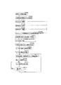
上述した、この実施形態における温度測定装置の動作フローを示すと、図3のようになる。まず、この実施形態における温度測定装置の電源をオンにして定電流を供給する(ST601)。これにより、マイコン4の対応関係作成開始手段46が切替手段32に対応関係作成開始コマンドを送信する(ST602)。切替手段32は、前記コマンドに従って回路の接続を切り替えて、先ず基準抵抗体Aに接続、通電する(ST603)。これにより、基準抵抗体Aの両端間の電圧値がフィルタ回路33を通ってアンプ装置34で増幅され、ADコンバータ35で取得される(ST606)。次に、切替手段32が接続を切り替えて、基準抵抗Bに接続、通電し(ST604)、同様に電圧値がADコンバータ35で取得される(ST606)。さらに、切替手段32が接続を切り替えて、基準抵抗Cに接続、通電し(ST605)、同様に電圧値がADコンバータ35で取得される(ST606)。
FIG. 3 shows an operation flow of the temperature measuring apparatus according to this embodiment described above. First, the temperature measuring device in this embodiment is turned on to supply a constant current (ST601). Thereby, the correspondence creation start means 46 of the
ADコンバータ35で取得された測定電圧値は、デジタル信号に変換され、マイコン4へ送信されて、既述のとおり、マイコン4の判断手段43は、各基準抵抗体における前記測定電圧値とそれに対応する各所定温度との対応関係を、センサ部2に定電流を供給して得られる測定電圧値とセンサ部2における温度値との対応関係と判断する(ST607)。
The measured voltage value acquired by the
ST607で判断した対応関係を基に、対応関係作成手段44は、前記対応関係を満たす関数式を作成する(ST608)。尚、作成された関数式は記憶手段41に格納される。 Based on the correspondence determined in ST607, the correspondence creation unit 44 creates a function expression that satisfies the correspondence (ST608). The created function formula is stored in the storage means 41.
次に、切替手段32は、接続を切り替えてセンサ部2に接続、通電し、センサ部2における温度値の測定を開始する(ST609)。センサ部2の両端間の電圧値が測定され(ST610)、ADコンバータに取得されデジタル信号に変換されて、マイコン4へ送信される。マイコン4の演算手段42は、前記送信された測定電圧値と前記関数式を参照して、センサ部2における温度値を算出する(ST611)。そして、算出された温度値は、有線又は無線の出力手段45により、外部機器等へ出力される(ST612)。
Next, the switching
以後、継続的にセンサ部2における前記測定電圧値の測定を繰り返し(ST613)、測定電圧値に変化があれば、再度温度値を算出する(ST611)。尚、ここでの電圧値の測定については、常時回路に定電流を供給して測定電圧値の変化を検知するようにしてもよいし、間欠的に定電流を供給して電圧値を測定し、温度値を算出するようにしてもよい。
Thereafter, the measurement of the measured voltage value in the
尚、本発明に係る温度測定装置の回路構成は、上述の実施形態のものに限られない。例えば、既述した従来の3導線式、あるいは4導線式の温度測定装置にも適用できる。またセンサ部2として、白金測温抵抗体のほか、サーミスタなど、温度の変化に応じてその抵抗値が変化する素子であれば、どのような素子を使用しても良い。好ましくは、測定すべき温度帯域において、温度変化に応じて比例的に抵抗値が変化する素子を選択して使用するのが良い。そのようにすれば、当該温度帯域においては、抵抗値(および測定電圧値)と温度値との関係が一次関数で示されるので、少ない数の基準抵抗体を利用して測定電圧値と温度値との関係を示す関数式(一次関数式)を作成でき、かつ正確な温度測定が可能となる。
The circuit configuration of the temperature measuring device according to the present invention is not limited to that of the above-described embodiment. For example, the present invention can also be applied to the above-described conventional three-conductor type or four-conductor type temperature measuring device. In addition to the platinum resistance thermometer, any element such as a thermistor may be used as the
1 温度測定装置
2 センサ部
31 定電流電源
32 切替手段
34 アンプ装置
35 ADコンバータ
4 マイコン
41 記憶手段
42 演算手段
43 判断手段
44 対応関係作成手段
45 出力手段
46 対応関係作成開始手段
5 基板
DESCRIPTION OF SYMBOLS 1
Claims (3)
前記センサ部が所定温度において有する抵抗値と同じ抵抗値を有し、温度変化によっても抵抗値が一定の基準抵抗体を前記センサ部に並列して配し、
定電流を前記基準抵抗体に流して得られた該基準抵抗体の両端間の測定電圧値から、測定電圧値と温度値との対応関係を求め、
該対応関係に基づいて、センサ部に定電流を供給して得られる該センサ部の両端間の測定電圧値から、センサ部における温度値を算出するようになされ、
且つ、前記センサ部として白金測温抵抗体が使用され、
前記基準抵抗体として、前記白金測温抵抗体の0℃における抵抗値と同じ抵抗値の基準抵抗体と、0℃を超える温度における抵抗値と同じ抵抗値の基準抵抗体と、0℃未満の温度における抵抗値と同じ抵抗値の基準抵抗体とを含む3つ以上の異なる抵抗値の前記基準抵抗体が、それぞれ前記センサ部と並列に配されて、
前記3つ以上の基準抵抗体についての前記測定電圧値と温度値との対応関係が、0℃以上の温度値において用いる関数式と、0℃以下の温度値において用いる関数式とでそれぞれ表されるとともに、
該関数式に基づいて、前記センサ部に定電流を供給して得られる該センサ部の両端間の測定電圧値から、前記センサ部における温度値を算出するようにしたことを特徴とする温度測定装置。 The temperature value in the sensor unit is calculated and output from the voltage value between both ends of the sensor unit obtained by supplying a constant current to the sensor unit consisting of a resistance element whose resistance value changes proportionally with temperature change A temperature measuring device,
The sensor unit has the same resistance value as the resistance value at a predetermined temperature, and a reference resistor having a constant resistance value due to a temperature change is arranged in parallel with the sensor unit,
From the measured voltage value between both ends of the reference resistor obtained by flowing a constant current through the reference resistor, the correspondence between the measured voltage value and the temperature value is obtained,
Based on the correspondence, a temperature value in the sensor unit is calculated from a measured voltage value between both ends of the sensor unit obtained by supplying a constant current to the sensor unit ,
And a platinum resistance thermometer is used as the sensor part,
As the reference resistor, a reference resistor having the same resistance value as that of the platinum resistance thermometer at 0 ° C., a reference resistor having the same resistance value as that at a temperature exceeding 0 ° C., and less than 0 ° C. The reference resistors having three or more different resistance values including a reference resistor having the same resistance value as the resistance value at the temperature are respectively arranged in parallel with the sensor unit,
The correspondence relationship between the measured voltage value and the temperature value for the three or more reference resistors is expressed by a function equation used at a temperature value of 0 ° C. or higher and a function equation used at a temperature value of 0 ° C. or lower, respectively. And
Based on the function formula, a temperature value in the sensor unit is calculated from a measured voltage value between both ends of the sensor unit obtained by supplying a constant current to the sensor unit. apparatus.
前記センサ部に定電流を供給する定電流電源と、
前記センサ部の両端間の電圧値を入力値とし、該入力値を増幅して出力するアンプ装置と、
前記アンプ装置から出力した測定電圧値をデジタル信号に変換するADコンバータと、
前記センサ部に定電流を流して得られる該センサ部の両端間の前記測定電圧値とそれに対応する温度値との対応関係を示す関数式又は対応関係データを格納する記憶手段と、
前記ADコンバータから出力された測定電圧値と前記関数式又は対応関係データとを参照して、温度値を算出する演算手段とを備える温度測定装置であって、
前記センサ部として白金測温抵抗体が使用され、
前記センサ部が所定温度において有する抵抗値と同じ抵抗値を有し、温度変化によっても抵抗値が一定の基準抵抗体であって、各々前記センサ部と並列に接続された、前記白金測温抵抗体の0℃における抵抗値と同じ抵抗値の基準抵抗体と、0℃を超える温度における抵抗値と同じ抵抗値の基準抵抗体と、0℃未満の温度における抵抗値と同じ抵抗値の基準抵抗体とを含む3つ以上の異なる抵抗値の基準抵抗体と、
前記センサ部及び前記各基準抵抗体のうちのいずれか一つに前記定電流電源からの定電流を供給するように接続を切り替える切替手段と、
前記切替手段により、前記各基準抵抗体それぞれに定電流を供給して得られた各基準抵抗体の両端間における測定電圧値を前記センサ部の各所定温度における測定電圧値として判断する判断手段と、
前記判断手段において判断した測定電圧値と温度値との対応関係を満たす関数式又は対応関係データを作成する対応関係作成手段とを備え、該対応関係作成手段において0℃以上の温度値において用いる関数式又は対応関係データと、0℃以下の温度値において用いる関数式又は対応関係データとがそれぞれ作成されると共に、前記演算手段において、センサ部に定電流を供給して得られる該センサ部の両端間の測定電圧値と前記関数式又は対応関係データとを参照して温度値を算出するようにしたことを特徴とする温度測定装置。 A sensor unit consisting of a resistance element whose resistance value changes proportionally with temperature change;
A constant current power source for supplying a constant current to the sensor unit;
The voltage value between both ends of the sensor unit as an input value, an amplifier device that amplifies and outputs the input value;
An AD converter that converts a measured voltage value output from the amplifier device into a digital signal;
Storage means for storing a functional expression or correspondence data indicating a correspondence relationship between the measured voltage value between both ends of the sensor portion obtained by flowing a constant current through the sensor portion and a temperature value corresponding thereto;
A temperature measurement apparatus comprising a calculation means for calculating a temperature value with reference to the measurement voltage value output from the AD converter and the functional expression or correspondence data,
A platinum resistance thermometer is used as the sensor unit,
The platinum resistance thermometer having a resistance value that is the same as the resistance value that the sensor unit has at a predetermined temperature, and a resistance value that is constant even with a temperature change, each connected in parallel with the sensor unit. A reference resistor having the same resistance value as the resistance value at 0 ° C., a reference resistor having the same resistance value as that at a temperature exceeding 0 ° C., and a reference resistor having the same resistance value as that at a temperature below 0 ° C. A reference resistor of three or more different resistance values including a body,
Switching means for switching connection so as to supply a constant current from the constant current power source to any one of the sensor unit and each of the reference resistors;
By the switching unit, a determination unit operable to determine a measured voltage value between both ends of the reference resistor body obtained by supplying a constant current to each of the reference resistors as a voltage value measured at each predetermined temperature of the sensor unit ,
A function formula that satisfies the correspondence relationship between the measured voltage value and the temperature value determined by the determination unit or a correspondence relationship creation unit that creates correspondence data, and the function used at a temperature value of 0 ° C. or higher in the correspondence relationship creation unit. Formulas or correspondence data and function formulas or correspondence data used at a temperature value of 0 ° C. or less are respectively created , and both ends of the sensor unit obtained by supplying a constant current to the sensor unit in the calculation unit A temperature measurement device characterized in that a temperature value is calculated with reference to a measured voltage value between the function expression and correspondence data.
Priority Applications (1)
| Application Number | Priority Date | Filing Date | Title |
|---|---|---|---|
| JP2009023822A JP5437654B2 (en) | 2009-02-04 | 2009-02-04 | Temperature measuring device |
Applications Claiming Priority (1)
| Application Number | Priority Date | Filing Date | Title |
|---|---|---|---|
| JP2009023822A JP5437654B2 (en) | 2009-02-04 | 2009-02-04 | Temperature measuring device |
Publications (2)
| Publication Number | Publication Date |
|---|---|
| JP2010181228A JP2010181228A (en) | 2010-08-19 |
| JP5437654B2 true JP5437654B2 (en) | 2014-03-12 |
Family
ID=42762889
Family Applications (1)
| Application Number | Title | Priority Date | Filing Date |
|---|---|---|---|
| JP2009023822A Expired - Fee Related JP5437654B2 (en) | 2009-02-04 | 2009-02-04 | Temperature measuring device |
Country Status (1)
| Country | Link |
|---|---|
| JP (1) | JP5437654B2 (en) |
Families Citing this family (3)
| Publication number | Priority date | Publication date | Assignee | Title |
|---|---|---|---|---|
| KR101810504B1 (en) * | 2017-02-01 | 2017-12-20 | 김원선 | Integrated analog signal processing apparatus and method thereof |
| CN113885359B (en) * | 2021-10-27 | 2024-05-10 | 江西洪都航空工业集团有限责任公司 | Semi-physical simulation atmospheric temperature simulation method |
| CN114513208A (en) * | 2021-12-30 | 2022-05-17 | 如果新能源科技(江苏)股份有限公司 | Parameter self-calibration system and control method thereof |
Family Cites Families (3)
| Publication number | Priority date | Publication date | Assignee | Title |
|---|---|---|---|---|
| JPH0755588A (en) * | 1993-08-10 | 1995-03-03 | Fujitsu Ltd | Temperature detector |
| JPH09986A (en) * | 1995-06-19 | 1997-01-07 | Hitachi Koki Co Ltd | Centrifuge temperature controller |
| JP2000241258A (en) * | 1999-02-25 | 2000-09-08 | T & D:Kk | Temperature measuring device and measuring method |
-
2009
- 2009-02-04 JP JP2009023822A patent/JP5437654B2/en not_active Expired - Fee Related
Also Published As
| Publication number | Publication date |
|---|---|
| JP2010181228A (en) | 2010-08-19 |
Similar Documents
| Publication | Publication Date | Title |
|---|---|---|
| ES2705433T3 (en) | Method for temperature drift compensation of temperature measurement device using thermocouple | |
| JP5009374B2 (en) | Detection of temperature sensor configuration in a process variable transmitter | |
| KR101610420B1 (en) | Arrangement for linearizing a non-linear sensor | |
| JP5981319B2 (en) | Intake air temperature sensor device and flow rate measuring device | |
| CN101957243B (en) | High-precision temperature measuring device and method | |
| US8874387B2 (en) | Air flow measurement device and air flow correction method | |
| KR102234155B1 (en) | System and method for correcting current value of shunt resistor | |
| JP4736508B2 (en) | Physical quantity detection method and sensor device | |
| JP4274385B1 (en) | Temperature measurement circuit in a flow meter | |
| CN103411699B (en) | A kind of high precision measuring temperature instrument | |
| JP5437654B2 (en) | Temperature measuring device | |
| KR101375363B1 (en) | Apparatus for measuring temperature using thermistor | |
| RU2677786C1 (en) | Temperature meter and method of measurement | |
| CN114112093B (en) | Thermal resistance temperature measurement circuit with sampling signal linearization function | |
| JP2008151596A (en) | Load cell and mass meter | |
| JPH102807A (en) | Thermocouple measuring device | |
| JP6489081B2 (en) | Sensor device | |
| JP4209429B2 (en) | Strain / temperature measurement method | |
| JP5579097B2 (en) | 4-wire RTD input circuit | |
| JP2011153972A (en) | Dynamic quantity sensor | |
| JP5523370B2 (en) | 4-wire RTD input circuit | |
| JP2000214030A (en) | Pressure sensor circuit | |
| JPWO2014068693A1 (en) | Anemometer | |
| JP5511120B2 (en) | Gas concentration detector | |
| JP2007285849A (en) | Gas concentration detector |
Legal Events
| Date | Code | Title | Description |
|---|---|---|---|
| A621 | Written request for application examination |
Free format text: JAPANESE INTERMEDIATE CODE: A621 Effective date: 20110926 |
|
| A977 | Report on retrieval |
Free format text: JAPANESE INTERMEDIATE CODE: A971007 Effective date: 20121212 |
|
| A131 | Notification of reasons for refusal |
Free format text: JAPANESE INTERMEDIATE CODE: A131 Effective date: 20121218 |
|
| A521 | Request for written amendment filed |
Free format text: JAPANESE INTERMEDIATE CODE: A523 Effective date: 20130213 |
|
| TRDD | Decision of grant or rejection written | ||
| A01 | Written decision to grant a patent or to grant a registration (utility model) |
Free format text: JAPANESE INTERMEDIATE CODE: A01 Effective date: 20131119 |
|
| A61 | First payment of annual fees (during grant procedure) |
Free format text: JAPANESE INTERMEDIATE CODE: A61 Effective date: 20131212 |
|
| R150 | Certificate of patent or registration of utility model |
Ref document number: 5437654 Country of ref document: JP Free format text: JAPANESE INTERMEDIATE CODE: R150 Free format text: JAPANESE INTERMEDIATE CODE: R150 |
|
| LAPS | Cancellation because of no payment of annual fees |