JP5456435B2 - 液体噴出器 - Google Patents
液体噴出器 Download PDFInfo
- Publication number
- JP5456435B2 JP5456435B2 JP2009246753A JP2009246753A JP5456435B2 JP 5456435 B2 JP5456435 B2 JP 5456435B2 JP 2009246753 A JP2009246753 A JP 2009246753A JP 2009246753 A JP2009246753 A JP 2009246753A JP 5456435 B2 JP5456435 B2 JP 5456435B2
- Authority
- JP
- Japan
- Prior art keywords
- cylinder
- hole
- peripheral wall
- contents
- container
- Prior art date
- Legal status (The legal status is an assumption and is not a legal conclusion. Google has not performed a legal analysis and makes no representation as to the accuracy of the status listed.)
- Active
Links
- 239000007788 liquid Substances 0.000 title claims description 17
- 230000002093 peripheral effect Effects 0.000 claims description 34
- 238000000034 method Methods 0.000 description 3
- 230000000630 rising effect Effects 0.000 description 3
- 238000005086 pumping Methods 0.000 description 2
- 244000273618 Sphenoclea zeylanica Species 0.000 description 1
- 210000000078 claw Anatomy 0.000 description 1
- 239000002537 cosmetic Substances 0.000 description 1
- 230000006837 decompression Effects 0.000 description 1
- -1 hair styling Substances 0.000 description 1
- 238000012856 packing Methods 0.000 description 1
- 239000002453 shampoo Substances 0.000 description 1
Images



Landscapes
- Containers And Packaging Bodies Having A Special Means To Remove Contents (AREA)
Description
前記ポンプのシリンダーに、該シリンダーを前記外気導入孔とともに取り囲んで該シリンダーの外周壁との間にて環状空間を形成するカバーを設け、
前記カバーに、該環状空間につながる少なくとも1つの貫通孔を設け、
前記カバーは、前記シリンダーの外周壁に沿う周壁と、該周壁の下端とつながり該シリンダーの外周壁と嵌合する底壁開口を有する底壁と、からなることを特徴とするものである。
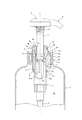
2 ベースキャップ
3 ポンプ
3a シリンダー
3a2 外気導入孔
3c ロッド
3d 環状ピストン
4 吸引管
5 押圧ヘッド
7 カバー
7c 貫通孔
8 係止部材
Claims (5)
- 容器の内側につながる貫通開口を有し、容器の口部に固定保持されるベースキャップと、少なくとも1つの外気導入孔を設けたシリンダーを備えるとともに該ベースキャップの貫通開口を通して吊り下げ保持されるポンプと、該ポンプのステムに連結し、該ステムの押し込みと復帰動作の繰り返しにより該ポンプを駆動させて容器内の内容物を吸引、加圧、圧送し、ノズルを通して外界へ排出する押圧ヘッドとを備えた液体噴出器であって、
前記ポンプのシリンダーに、該シリンダーを前記外気導入孔とともに取り囲んで該シリンダーの外周壁との間にて環状空間を形成するカバーを設け、
前記カバーに、該環状空間につながる少なくとも1つの貫通孔を設け、
前記カバーは、前記シリンダーの外周壁に沿う周壁と、該周壁の下端とつながり該シリンダーの外周壁と嵌合する底壁開口を有する底壁と、からなることを特徴とする液体噴出器。 - 前記貫通孔は、前記外気導入孔よりも下方に位置する、前記周壁に設けられていることを特徴とする請求項1記載の液体噴出器。
- 前記貫通孔は、前記底壁に設けられていることを特徴とする請求項1記載の液体噴出器。
- 前記貫通孔の前記シリンダーの軸心に向かって開口する向きと、前記外気導入孔の前記シリンダーの軸心に向かって開口する向きとは異なる向きであることを特徴とする、請求項1〜3の何れかに記載の液体噴出器。
- 前記シリンダーの内部空間をAとし、前記環状空間をBとした場合に、A≦Bの条件を満足するものである、請求項1〜4の何れかに記載の液体噴出器。
Priority Applications (1)
| Application Number | Priority Date | Filing Date | Title |
|---|---|---|---|
| JP2009246753A JP5456435B2 (ja) | 2009-10-27 | 2009-10-27 | 液体噴出器 |
Applications Claiming Priority (1)
| Application Number | Priority Date | Filing Date | Title |
|---|---|---|---|
| JP2009246753A JP5456435B2 (ja) | 2009-10-27 | 2009-10-27 | 液体噴出器 |
Publications (2)
| Publication Number | Publication Date |
|---|---|
| JP2011093539A JP2011093539A (ja) | 2011-05-12 |
| JP5456435B2 true JP5456435B2 (ja) | 2014-03-26 |
Family
ID=44110929
Family Applications (1)
| Application Number | Title | Priority Date | Filing Date |
|---|---|---|---|
| JP2009246753A Active JP5456435B2 (ja) | 2009-10-27 | 2009-10-27 | 液体噴出器 |
Country Status (1)
| Country | Link |
|---|---|
| JP (1) | JP5456435B2 (ja) |
Families Citing this family (2)
| Publication number | Priority date | Publication date | Assignee | Title |
|---|---|---|---|---|
| WO2012144202A1 (ja) | 2011-04-19 | 2012-10-26 | パナソニック株式会社 | 中継方法、中継装置 |
| JP6764720B2 (ja) * | 2016-07-29 | 2020-10-07 | 株式会社吉野工業所 | 吐出容器 |
Family Cites Families (4)
| Publication number | Priority date | Publication date | Assignee | Title |
|---|---|---|---|---|
| JPH0740512U (ja) * | 1993-12-22 | 1995-07-18 | 株式会社吉野工業所 | 特殊成分吸着防止アダプター |
| JP3822352B2 (ja) * | 1998-03-19 | 2006-09-20 | 株式会社吉野工業所 | 正倒立両用の液体噴出器 |
| JP3751450B2 (ja) * | 1998-09-25 | 2006-03-01 | 株式会社吉野工業所 | 液体噴出容器 |
| JP2005103360A (ja) * | 2003-09-29 | 2005-04-21 | Mitani Valve Co Ltd | 噴出ポンプ装置、および噴出器 |
-
2009
- 2009-10-27 JP JP2009246753A patent/JP5456435B2/ja active Active
Also Published As
| Publication number | Publication date |
|---|---|
| JP2011093539A (ja) | 2011-05-12 |
Similar Documents
| Publication | Publication Date | Title |
|---|---|---|
| EP2933206A1 (en) | Synthetic resin container having inverted, folded back bottom wall | |
| AU2894200A (en) | Pump dispenser having one-piece plastic spring and gasket | |
| KR20180111365A (ko) | 디스펜서 펌프 | |
| JP5456435B2 (ja) | 液体噴出器 | |
| US6364622B1 (en) | Vibratory pump apparatus | |
| JP2011073719A (ja) | 吐出ポンプ | |
| JP2009022935A (ja) | ポンプディスペンサー | |
| JP2004330000A (ja) | 縦形ポンプ付きデラミボトル | |
| JP5476084B2 (ja) | 反転、折返し底壁を備えた合成樹脂製容器 | |
| JP5229822B2 (ja) | 定量ポンプ | |
| JP2010173686A (ja) | 吸上げパイプ付き容器 | |
| US10376909B2 (en) | Pump type dispenser | |
| JP5650495B2 (ja) | ポンプ式注出器 | |
| JP6161388B2 (ja) | ディスペンサの吸引パイプ連結用アダプター | |
| JP3221629U (ja) | ポンプ | |
| JP4828324B2 (ja) | 液体吐出装置 | |
| JP4277990B2 (ja) | 液体噴出器 | |
| JP2005206218A (ja) | ポンプ式噴出装置、および噴出器 | |
| JP7055554B2 (ja) | 吐出具及び吐出容器 | |
| JP4400908B2 (ja) | スプレーノズル | |
| JP5825958B2 (ja) | 吐出ポンプ | |
| JP7475792B2 (ja) | 吐出具及び吐出容器 | |
| JP2002039055A (ja) | ポンプユニットおよびポンプ付き容器 | |
| JP2003192067A (ja) | ポンプ吐出器を備えた容器 | |
| JP3973895B2 (ja) | ポンプ吐出器 |
Legal Events
| Date | Code | Title | Description |
|---|---|---|---|
| A621 | Written request for application examination |
Free format text: JAPANESE INTERMEDIATE CODE: A621 Effective date: 20120426 |
|
| A977 | Report on retrieval |
Free format text: JAPANESE INTERMEDIATE CODE: A971007 Effective date: 20130514 |
|
| A131 | Notification of reasons for refusal |
Free format text: JAPANESE INTERMEDIATE CODE: A131 Effective date: 20130813 |
|
| A521 | Request for written amendment filed |
Free format text: JAPANESE INTERMEDIATE CODE: A523 Effective date: 20131011 |
|
| TRDD | Decision of grant or rejection written | ||
| A01 | Written decision to grant a patent or to grant a registration (utility model) |
Free format text: JAPANESE INTERMEDIATE CODE: A01 Effective date: 20140107 |
|
| A61 | First payment of annual fees (during grant procedure) |
Free format text: JAPANESE INTERMEDIATE CODE: A61 Effective date: 20140108 |
|
| R150 | Certificate of patent or registration of utility model |
Ref document number: 5456435 Country of ref document: JP Free format text: JAPANESE INTERMEDIATE CODE: R150 Free format text: JAPANESE INTERMEDIATE CODE: R150 |