JP5583368B2 - 予混合直接噴射ノズル - Google Patents
予混合直接噴射ノズル Download PDFInfo
- Publication number
- JP5583368B2 JP5583368B2 JP2009173798A JP2009173798A JP5583368B2 JP 5583368 B2 JP5583368 B2 JP 5583368B2 JP 2009173798 A JP2009173798 A JP 2009173798A JP 2009173798 A JP2009173798 A JP 2009173798A JP 5583368 B2 JP5583368 B2 JP 5583368B2
- Authority
- JP
- Japan
- Prior art keywords
- body portion
- fuel
- peripheral wall
- injection nozzle
- outer peripheral
- Prior art date
- Legal status (The legal status is an assumption and is not a legal conclusion. Google has not performed a legal analysis and makes no representation as to the accuracy of the status listed.)
- Active
Links
Images


Classifications
-
- F—MECHANICAL ENGINEERING; LIGHTING; HEATING; WEAPONS; BLASTING
- F23—COMBUSTION APPARATUS; COMBUSTION PROCESSES
- F23R—GENERATING COMBUSTION PRODUCTS OF HIGH PRESSURE OR HIGH VELOCITY, e.g. GAS-TURBINE COMBUSTION CHAMBERS
- F23R3/00—Continuous combustion chambers using liquid or gaseous fuel
- F23R3/28—Continuous combustion chambers using liquid or gaseous fuel characterised by the fuel supply
- F23R3/286—Continuous combustion chambers using liquid or gaseous fuel characterised by the fuel supply having fuel-air premixing devices
-
- F—MECHANICAL ENGINEERING; LIGHTING; HEATING; WEAPONS; BLASTING
- F23—COMBUSTION APPARATUS; COMBUSTION PROCESSES
- F23R—GENERATING COMBUSTION PRODUCTS OF HIGH PRESSURE OR HIGH VELOCITY, e.g. GAS-TURBINE COMBUSTION CHAMBERS
- F23R3/00—Continuous combustion chambers using liquid or gaseous fuel
- F23R3/28—Continuous combustion chambers using liquid or gaseous fuel characterised by the fuel supply
- F23R3/283—Attaching or cooling of fuel injecting means including supports for fuel injectors, stems, or lances
Landscapes
- Engineering & Computer Science (AREA)
- Chemical & Material Sciences (AREA)
- Combustion & Propulsion (AREA)
- Mechanical Engineering (AREA)
- General Engineering & Computer Science (AREA)
- Gas Burners (AREA)
- Turbine Rotor Nozzle Sealing (AREA)
Description
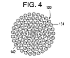
第1の端部154は、管130の束(管束121)の流体出口135に隣接して主本体部分111に連結される。図3で最もよく分かるように、第2の本体部分は、第1の端部154及び第2の端部155間で収束して、管束121の下流に加速ゾーン150を形成する。このことは、流体出口135から流出した後に燃料及び空気の連続的な混合を生じさせかつ加速ゾーン150及び第2の端部155の外部の火炎ゾーンに向けて燃料/空気混合気を加速する作用を有する。管束121は、個々の管130の第2の端部セクション132に沿って球状遮蔽ドームの形態になった面160を形成する。ドーム形状は、内周壁153の周辺部に沿った管130が加速ゾーン150内に落ち込む流体出口135における急激な面積拡大を防止することを意図している。
11 圧縮機
14 燃焼器組立体
16 燃焼器組立体壁
12 燃焼室
110 予混合装置又はノズル
21 燃料入口
30 タービン
31 圧縮機/タービンシャフト
111 主本体部分
112 外周壁
113 内周壁
114 燃料流路
115 内部空間
116 入口端部
121 管束
117 出口端部
130 燃料/空気混合管
136 バンド
131 第1の端部セクション
132 第2の端部セクション
133 中間部分
134 第1の流体入口
135 流体出口
141 燃料プレナム
142 流体入口
150 混合ゾーン
151 第2の本体部分
152 外周壁
153 内周壁
154 第1の端部
155 第2の端部
160 面
171 冷却媒体プレナム
172 オリフィス
173 冷却通路
174 ブリード孔
181 冷却通路
182 入口オリフィス
183 冷却出口オリフィス
Claims (13)
- 外周壁(112)を有する主本体部分(111)と、
前記主本体部分(111)内に配置された複数の燃料/空気混合管(130)と、
前記複数の燃料/空気混合管(130)に流体連結された燃料流路(114)と、
外周壁(152)を有しかつ第1の端部(154)と反対側の第2の端部(155)の間で延びる第2の本体部分(151)と、
第2の本体部分(151)に設けられかつ少なくとも部分的に前記第2の本体部分(151)の外周壁(152)に沿って延びる第1の冷却通路(181)と
を備えていて、第1の端部(154)が、前記複数の燃料/空気混合管(130)に隣接して前記主本体部分(111)に連結され、第2の本体部分(151)が、第1の端部(154)から第2の端部(155)に向かって収束する、噴射ノズル(110)。 - 前記複数の燃料/空気混合管(130)に隣接して設置された第2の冷却通路(173)を含む、請求項1記載の噴射ノズル。
- 前記複数の燃料/空気混合管(130)が互いに取付けられて単一の管束(121)を形成する、請求項1又は請求項2記載の噴射ノズル。
- 前記第1の冷却通路(181)が前記第2の本体部分(151)の外周壁(152)に設けられた複数の入口オリフィス(182)を含む、請求項1乃至請求項3のいずれか1項記載の噴射ノズル。
- 前記冷却入口オリフィス(182)が前記第2の本体部分(151)の外周壁(152)に対して略直角である、請求項4記載の噴射ノズル。
- 前記第1の冷却通路(181)が前記第2の本体部分(151)の外周壁(152)と内周壁(153)の間のギャップ内に形成される、請求項1乃至請求項5のいずれか1項記載の噴射ノズル。
- 前記第2の本体部分(151)の内周壁(153)及び外周壁(152)が略同心に間隔を置いて配置される、請求項6記載の噴射ノズル。
- 前記第1の冷却通路(181)が前記第2の本体部分(151)の内周壁(153)に設けられた冷却出口オリフィス(183)を含む、請求項7記載の噴射ノズル。
- 前記燃料流路(114)が前記主本体部分(111)の外周壁(112)と内周壁(113)の間に配置され、前記主本体部分(111)の内周壁(113)の内側の内部空間(115)に空気が供給される、請求項1乃至請求項8のいずれか1項記載の噴射ノズル。
- 前記複数の燃料/空気混合管(130)の各々が第1の端部セクション(131)から中間部分(133)を通って第2の端部セクション(132)まで延びており、前記第1の端部セクション(131)に第1の流体入口(134)が形成され、前記第2の端部セクション(132)に流体出口(135)が形成されている、請求項1乃至請求項9のいずれか1項記載の噴射ノズル。
- 前記複数の燃料/空気混合管(130)が互いに取付けられて単一の管束(121)を形成しており、前記管束(121)が、前記第2の端部セクション(132)に沿ってドーム形状の面(160)を形成している、請求項10記載の噴射ノズル。
- 前記燃料流路(114)が、燃料プレナム(141)を介して、前記燃料/空気混合管(130)の第2の流体入口(142)に流体連結されている、請求項10又は請求項11記載の噴射ノズル。
- 燃料/空気混合気が、前記第2の本体部分(151)の第2の端部(155)の下流に位置する燃焼室(12)内で点火される、請求項1乃至請求項12のいずれか1項記載の噴射ノズル。
Applications Claiming Priority (2)
| Application Number | Priority Date | Filing Date | Title |
|---|---|---|---|
| US12/245,266 US7886991B2 (en) | 2008-10-03 | 2008-10-03 | Premixed direct injection nozzle |
| US12/245,266 | 2008-10-03 |
Publications (2)
| Publication Number | Publication Date |
|---|---|
| JP2010091258A JP2010091258A (ja) | 2010-04-22 |
| JP5583368B2 true JP5583368B2 (ja) | 2014-09-03 |
Family
ID=41795203
Family Applications (1)
| Application Number | Title | Priority Date | Filing Date |
|---|---|---|---|
| JP2009173798A Active JP5583368B2 (ja) | 2008-10-03 | 2009-07-27 | 予混合直接噴射ノズル |
Country Status (5)
| Country | Link |
|---|---|
| US (1) | US7886991B2 (ja) |
| JP (1) | JP5583368B2 (ja) |
| CN (1) | CN101713541B (ja) |
| CH (1) | CH699684B1 (ja) |
| DE (1) | DE102009026313A1 (ja) |
Families Citing this family (53)
| Publication number | Priority date | Publication date | Assignee | Title |
|---|---|---|---|---|
| US8147121B2 (en) * | 2008-07-09 | 2012-04-03 | General Electric Company | Pre-mixing apparatus for a turbine engine |
| US8112999B2 (en) * | 2008-08-05 | 2012-02-14 | General Electric Company | Turbomachine injection nozzle including a coolant delivery system |
| JP4961415B2 (ja) * | 2008-12-04 | 2012-06-27 | 株式会社日立製作所 | ガスタービン燃焼器 |
| JP5180807B2 (ja) | 2008-12-24 | 2013-04-10 | 三菱重工業株式会社 | 1段静翼の冷却構造、及びガスタービン |
| US8297059B2 (en) * | 2009-01-22 | 2012-10-30 | General Electric Company | Nozzle for a turbomachine |
| US9140454B2 (en) * | 2009-01-23 | 2015-09-22 | General Electric Company | Bundled multi-tube nozzle for a turbomachine |
| US8539773B2 (en) * | 2009-02-04 | 2013-09-24 | General Electric Company | Premixed direct injection nozzle for highly reactive fuels |
| US8616002B2 (en) * | 2009-07-23 | 2013-12-31 | General Electric Company | Gas turbine premixing systems |
| JP5479058B2 (ja) * | 2009-12-07 | 2014-04-23 | 三菱重工業株式会社 | 燃焼器とタービン部との連通構造、および、ガスタービン |
| US8800289B2 (en) | 2010-09-08 | 2014-08-12 | General Electric Company | Apparatus and method for mixing fuel in a gas turbine nozzle |
| US8925324B2 (en) | 2010-10-05 | 2015-01-06 | General Electric Company | Turbomachine including a mixing tube element having a vortex generator |
| US9010083B2 (en) | 2011-02-03 | 2015-04-21 | General Electric Company | Apparatus for mixing fuel in a gas turbine |
| US9373984B2 (en) | 2011-06-29 | 2016-06-21 | General Electric Company | Electrical machine |
| US8904797B2 (en) | 2011-07-29 | 2014-12-09 | General Electric Company | Sector nozzle mounting systems |
| US9506654B2 (en) | 2011-08-19 | 2016-11-29 | General Electric Company | System and method for reducing combustion dynamics in a combustor |
| US8984887B2 (en) | 2011-09-25 | 2015-03-24 | General Electric Company | Combustor and method for supplying fuel to a combustor |
| US8801428B2 (en) | 2011-10-04 | 2014-08-12 | General Electric Company | Combustor and method for supplying fuel to a combustor |
| US9243803B2 (en) * | 2011-10-06 | 2016-01-26 | General Electric Company | System for cooling a multi-tube fuel nozzle |
| US20130091858A1 (en) * | 2011-10-14 | 2013-04-18 | General Electric Company | Effusion cooled nozzle and related method |
| US8550809B2 (en) | 2011-10-20 | 2013-10-08 | General Electric Company | Combustor and method for conditioning flow through a combustor |
| US9188335B2 (en) | 2011-10-26 | 2015-11-17 | General Electric Company | System and method for reducing combustion dynamics and NOx in a combustor |
| US9033699B2 (en) | 2011-11-11 | 2015-05-19 | General Electric Company | Combustor |
| US8894407B2 (en) | 2011-11-11 | 2014-11-25 | General Electric Company | Combustor and method for supplying fuel to a combustor |
| US9004912B2 (en) | 2011-11-11 | 2015-04-14 | General Electric Company | Combustor and method for supplying fuel to a combustor |
| US9366440B2 (en) | 2012-01-04 | 2016-06-14 | General Electric Company | Fuel nozzles with mixing tubes surrounding a liquid fuel cartridge for injecting fuel in a gas turbine combustor |
| US9322557B2 (en) | 2012-01-05 | 2016-04-26 | General Electric Company | Combustor and method for distributing fuel in the combustor |
| JP5331909B2 (ja) * | 2012-02-17 | 2013-10-30 | 株式会社日立製作所 | 燃焼器 |
| US9341376B2 (en) | 2012-02-20 | 2016-05-17 | General Electric Company | Combustor and method for supplying fuel to a combustor |
| US9052112B2 (en) | 2012-02-27 | 2015-06-09 | General Electric Company | Combustor and method for purging a combustor |
| US9121612B2 (en) | 2012-03-01 | 2015-09-01 | General Electric Company | System and method for reducing combustion dynamics in a combustor |
| US8511086B1 (en) | 2012-03-01 | 2013-08-20 | General Electric Company | System and method for reducing combustion dynamics in a combustor |
| RU2633249C2 (ru) * | 2012-03-29 | 2017-10-11 | Ансалдо Энерджиа Свитзерлэнд Аг | Камера сгорания газовой турбины |
| US9267690B2 (en) | 2012-05-29 | 2016-02-23 | General Electric Company | Turbomachine combustor nozzle including a monolithic nozzle component and method of forming the same |
| US9249734B2 (en) | 2012-07-10 | 2016-02-02 | General Electric Company | Combustor |
| US8904798B2 (en) * | 2012-07-31 | 2014-12-09 | General Electric Company | Combustor |
| US9677766B2 (en) * | 2012-11-28 | 2017-06-13 | General Electric Company | Fuel nozzle for use in a turbine engine and method of assembly |
| US9353950B2 (en) | 2012-12-10 | 2016-05-31 | General Electric Company | System for reducing combustion dynamics and NOx in a combustor |
| US9371997B2 (en) | 2013-07-01 | 2016-06-21 | General Electric Company | System for supporting a bundled tube fuel injector within a combustor |
| US9322555B2 (en) | 2013-07-01 | 2016-04-26 | General Electric Company | Cap assembly for a bundled tube fuel injector |
| US9273868B2 (en) | 2013-08-06 | 2016-03-01 | General Electric Company | System for supporting bundled tube segments within a combustor |
| DE102013016201A1 (de) * | 2013-09-28 | 2015-04-02 | Dürr Systems GmbH | "Brennerkopf eines Brenners und Gasturbine mit einem solchen Brenner" |
| US9423135B2 (en) | 2013-11-21 | 2016-08-23 | General Electric Company | Combustor having mixing tube bundle with baffle arrangement for directing fuel |
| US9435540B2 (en) | 2013-12-11 | 2016-09-06 | General Electric Company | Fuel injector with premix pilot nozzle |
| CN103925137B (zh) * | 2014-03-19 | 2016-09-28 | 成都绿迪科技有限公司 | 发动机燃油喷嘴 |
| US10030869B2 (en) | 2014-11-26 | 2018-07-24 | General Electric Company | Premix fuel nozzle assembly |
| US9714767B2 (en) | 2014-11-26 | 2017-07-25 | General Electric Company | Premix fuel nozzle assembly |
| US9982892B2 (en) | 2015-04-16 | 2018-05-29 | General Electric Company | Fuel nozzle assembly including a pilot nozzle |
| US9803867B2 (en) | 2015-04-21 | 2017-10-31 | General Electric Company | Premix pilot nozzle |
| US10145561B2 (en) | 2016-09-06 | 2018-12-04 | General Electric Company | Fuel nozzle assembly with resonator |
| US11525578B2 (en) | 2017-08-16 | 2022-12-13 | General Electric Company | Dynamics-mitigating adapter for bundled tube fuel nozzle |
| CN111174232A (zh) * | 2018-11-12 | 2020-05-19 | 中国联合重型燃气轮机技术有限公司 | 燃气轮机及其微混合喷嘴 |
| US12553385B2 (en) | 2020-03-30 | 2026-02-17 | Ge Vernova Infrastructure Technology Llc | Compact turbomachine combustor |
| KR102733280B1 (ko) | 2022-11-30 | 2024-11-25 | 두산에너빌리티 주식회사 | 노즐 어셈블리, 연소기 및 이를 포함하는 가스터빈 |
Family Cites Families (16)
| Publication number | Priority date | Publication date | Assignee | Title |
|---|---|---|---|---|
| US4100733A (en) * | 1976-10-04 | 1978-07-18 | United Technologies Corporation | Premix combustor |
| DE2950535A1 (de) * | 1979-11-23 | 1981-06-11 | BBC AG Brown, Boveri & Cie., Baden, Aargau | Brennkammer einer gasturbine mit vormisch/vorverdampf-elementen |
| US5435139A (en) * | 1991-03-22 | 1995-07-25 | Rolls-Royce Plc | Removable combustor liner for gas turbine engine combustor |
| US5263325A (en) * | 1991-12-16 | 1993-11-23 | United Technologies Corporation | Low NOx combustion |
| DE4443864A1 (de) * | 1994-12-09 | 1996-06-13 | Abb Management Ag | Gek}hltes Wandteil |
| JP3619626B2 (ja) * | 1996-11-29 | 2005-02-09 | 株式会社東芝 | ガスタービン燃焼器の運転方法 |
| EP0918190A1 (de) * | 1997-11-21 | 1999-05-26 | Abb Research Ltd. | Brenner für den Betrieb eines Wärmeerzeugers |
| US6237344B1 (en) * | 1998-07-20 | 2001-05-29 | General Electric Company | Dimpled impingement baffle |
| US6363724B1 (en) * | 2000-08-31 | 2002-04-02 | General Electric Company | Gas only nozzle fuel tip |
| EP1426558A3 (en) * | 2002-11-22 | 2005-02-09 | General Electric Company | Gas turbine transition piece with dimpled surface and cooling method for such a transition piece |
| US7146815B2 (en) * | 2003-07-31 | 2006-12-12 | United Technologies Corporation | Combustor |
| US7363763B2 (en) * | 2003-10-23 | 2008-04-29 | United Technologies Corporation | Combustor |
| US7007477B2 (en) * | 2004-06-03 | 2006-03-07 | General Electric Company | Premixing burner with impingement cooled centerbody and method of cooling centerbody |
| US20060191268A1 (en) * | 2005-02-25 | 2006-08-31 | General Electric Company | Method and apparatus for cooling gas turbine fuel nozzles |
| CN101614395B (zh) * | 2005-06-24 | 2012-01-18 | 株式会社日立制作所 | 喷烧器及喷烧器的冷却方法 |
| US7810333B2 (en) | 2006-10-02 | 2010-10-12 | General Electric Company | Method and apparatus for operating a turbine engine |
-
2008
- 2008-10-03 US US12/245,266 patent/US7886991B2/en active Active
-
2009
- 2009-07-24 CH CH01169/09A patent/CH699684B1/de not_active IP Right Cessation
- 2009-07-27 JP JP2009173798A patent/JP5583368B2/ja active Active
- 2009-08-03 DE DE102009026313A patent/DE102009026313A1/de not_active Withdrawn
- 2009-08-03 CN CN200910164171.7A patent/CN101713541B/zh not_active Expired - Fee Related
Also Published As
| Publication number | Publication date |
|---|---|
| CN101713541A (zh) | 2010-05-26 |
| US7886991B2 (en) | 2011-02-15 |
| DE102009026313A1 (de) | 2010-04-08 |
| JP2010091258A (ja) | 2010-04-22 |
| CH699684B1 (de) | 2013-09-13 |
| CH699684A2 (de) | 2010-04-15 |
| CN101713541B (zh) | 2014-01-29 |
| US20100084490A1 (en) | 2010-04-08 |
Similar Documents
| Publication | Publication Date | Title |
|---|---|---|
| JP2010091258A (ja) | 予混合直接噴射ノズル | |
| JP5530131B2 (ja) | ガスタービン燃焼器用の耐保炎性燃料/空気予混合器 | |
| JP5432683B2 (ja) | 予混合直接噴射ノズル | |
| JP5606776B2 (ja) | 燃焼システムにおいて燃料ノズルを熱的に保護するための方法及びシステム | |
| US8113000B2 (en) | Flashback resistant pre-mixer assembly | |
| JP6736284B2 (ja) | 予混合燃料ノズル組立体 | |
| JP5860620B2 (ja) | ターボ機械用噴射ノズル | |
| JP6659344B2 (ja) | 燃焼器内で冷却空気を利用するシステム及び方法 | |
| EP2239506B1 (en) | Premixing direct injector | |
| CN102844622B (zh) | 一种多燃料燃烧系统 | |
| EP2993404B1 (en) | Dilution gas or air mixer for a combustor of a gas turbine | |
| JP2012017971A5 (ja) | ||
| JP2014122784A (ja) | 燃焼器に燃料を供給するためのシステム | |
| US10030869B2 (en) | Premix fuel nozzle assembly | |
| JP2013181746A (ja) | 燃焼器内の燃焼ダイナミックスを小さくするためのシステムおよび方法 | |
| JP2017166479A (ja) | ガスタービンの流れスリーブの取り付け | |
| JP6595010B2 (ja) | 予混合保炎器を有する燃料ノズルアセンブリ | |
| KR102762432B1 (ko) | 노즐 어셈블리, 연소기 및 이를 포함하는 가스터빈 | |
| US20240263791A1 (en) | Hydrogen fuel distributor | |
| EP3220048B1 (en) | Combustion liner cooling |
Legal Events
| Date | Code | Title | Description |
|---|---|---|---|
| A621 | Written request for application examination |
Free format text: JAPANESE INTERMEDIATE CODE: A621 Effective date: 20120724 |
|
| A977 | Report on retrieval |
Free format text: JAPANESE INTERMEDIATE CODE: A971007 Effective date: 20130820 |
|
| A131 | Notification of reasons for refusal |
Free format text: JAPANESE INTERMEDIATE CODE: A131 Effective date: 20130827 |
|
| A601 | Written request for extension of time |
Free format text: JAPANESE INTERMEDIATE CODE: A601 Effective date: 20131127 |
|
| A602 | Written permission of extension of time |
Free format text: JAPANESE INTERMEDIATE CODE: A602 Effective date: 20131202 |
|
| A601 | Written request for extension of time |
Free format text: JAPANESE INTERMEDIATE CODE: A601 Effective date: 20131224 |
|
| A602 | Written permission of extension of time |
Free format text: JAPANESE INTERMEDIATE CODE: A602 Effective date: 20131227 |
|
| A601 | Written request for extension of time |
Free format text: JAPANESE INTERMEDIATE CODE: A601 Effective date: 20140127 |
|
| A602 | Written permission of extension of time |
Free format text: JAPANESE INTERMEDIATE CODE: A602 Effective date: 20140130 |
|
| A521 | Request for written amendment filed |
Free format text: JAPANESE INTERMEDIATE CODE: A523 Effective date: 20140227 |
|
| TRDD | Decision of grant or rejection written | ||
| A01 | Written decision to grant a patent or to grant a registration (utility model) |
Free format text: JAPANESE INTERMEDIATE CODE: A01 Effective date: 20140617 |
|
| A61 | First payment of annual fees (during grant procedure) |
Free format text: JAPANESE INTERMEDIATE CODE: A61 Effective date: 20140716 |
|
| R150 | Certificate of patent or registration of utility model |
Ref document number: 5583368 Country of ref document: JP Free format text: JAPANESE INTERMEDIATE CODE: R150 |
|
| R250 | Receipt of annual fees |
Free format text: JAPANESE INTERMEDIATE CODE: R250 |
|
| R250 | Receipt of annual fees |
Free format text: JAPANESE INTERMEDIATE CODE: R250 |
|
| R250 | Receipt of annual fees |
Free format text: JAPANESE INTERMEDIATE CODE: R250 |
|
| R250 | Receipt of annual fees |
Free format text: JAPANESE INTERMEDIATE CODE: R250 |
|
| R250 | Receipt of annual fees |
Free format text: JAPANESE INTERMEDIATE CODE: R250 |
|
| R250 | Receipt of annual fees |
Free format text: JAPANESE INTERMEDIATE CODE: R250 |
|
| R250 | Receipt of annual fees |
Free format text: JAPANESE INTERMEDIATE CODE: R250 |
|
| S111 | Request for change of ownership or part of ownership |
Free format text: JAPANESE INTERMEDIATE CODE: R313113 |
|
| R350 | Written notification of registration of transfer |
Free format text: JAPANESE INTERMEDIATE CODE: R350 |
|
| R250 | Receipt of annual fees |
Free format text: JAPANESE INTERMEDIATE CODE: R250 |
|
| R250 | Receipt of annual fees |
Free format text: JAPANESE INTERMEDIATE CODE: R250 |