JP5584552B2 - Objective lens for optical information recording / reproducing apparatus, and optical information recording / reproducing apparatus - Google Patents
Objective lens for optical information recording / reproducing apparatus, and optical information recording / reproducing apparatus Download PDFInfo
- Publication number
- JP5584552B2 JP5584552B2 JP2010178722A JP2010178722A JP5584552B2 JP 5584552 B2 JP5584552 B2 JP 5584552B2 JP 2010178722 A JP2010178722 A JP 2010178722A JP 2010178722 A JP2010178722 A JP 2010178722A JP 5584552 B2 JP5584552 B2 JP 5584552B2
- Authority
- JP
- Japan
- Prior art keywords
- optical
- region
- wavelength
- recording
- objective lens
- Prior art date
- Legal status (The legal status is an assumption and is not a legal conclusion. Google has not performed a legal analysis and makes no representation as to the accuracy of the status listed.)
- Expired - Fee Related
Links
- 230000003287 optical effect Effects 0.000 title claims description 280
- 238000007665 sagging Methods 0.000 claims description 29
- 239000011241 protective layer Substances 0.000 claims description 16
- 230000004907 flux Effects 0.000 claims description 8
- 230000004075 alteration Effects 0.000 description 23
- 230000002093 peripheral effect Effects 0.000 description 12
- 230000000052 comparative effect Effects 0.000 description 7
- 238000010586 diagram Methods 0.000 description 7
- 210000001747 pupil Anatomy 0.000 description 7
- 238000002834 transmittance Methods 0.000 description 7
- 230000000694 effects Effects 0.000 description 6
- 239000004065 semiconductor Substances 0.000 description 6
- 239000000203 mixture Substances 0.000 description 5
- 230000008859 change Effects 0.000 description 4
- 230000007423 decrease Effects 0.000 description 4
- 238000000465 moulding Methods 0.000 description 4
- 239000011347 resin Substances 0.000 description 3
- 229920005989 resin Polymers 0.000 description 3
- 206010010071 Coma Diseases 0.000 description 2
- 238000013459 approach Methods 0.000 description 2
- 230000005540 biological transmission Effects 0.000 description 2
- 230000007246 mechanism Effects 0.000 description 2
- 230000002411 adverse Effects 0.000 description 1
- 230000015572 biosynthetic process Effects 0.000 description 1
- 230000006866 deterioration Effects 0.000 description 1
- 239000000428 dust Substances 0.000 description 1
- 238000003384 imaging method Methods 0.000 description 1
- 238000001746 injection moulding Methods 0.000 description 1
- 238000009434 installation Methods 0.000 description 1
- 238000012986 modification Methods 0.000 description 1
- 230000004048 modification Effects 0.000 description 1
- 238000010606 normalization Methods 0.000 description 1
- 230000010363 phase shift Effects 0.000 description 1
Images




Classifications
-
- G—PHYSICS
- G11—INFORMATION STORAGE
- G11B—INFORMATION STORAGE BASED ON RELATIVE MOVEMENT BETWEEN RECORD CARRIER AND TRANSDUCER
- G11B7/00—Recording or reproducing by optical means, e.g. recording using a thermal beam of optical radiation by modifying optical properties or the physical structure, reproducing using an optical beam at lower power by sensing optical properties; Record carriers therefor
- G11B7/12—Heads, e.g. forming of the optical beam spot or modulation of the optical beam
- G11B7/135—Means for guiding the beam from the source to the record carrier or from the record carrier to the detector
- G11B7/1353—Diffractive elements, e.g. holograms or gratings
-
- G—PHYSICS
- G11—INFORMATION STORAGE
- G11B—INFORMATION STORAGE BASED ON RELATIVE MOVEMENT BETWEEN RECORD CARRIER AND TRANSDUCER
- G11B7/00—Recording or reproducing by optical means, e.g. recording using a thermal beam of optical radiation by modifying optical properties or the physical structure, reproducing using an optical beam at lower power by sensing optical properties; Record carriers therefor
- G11B7/12—Heads, e.g. forming of the optical beam spot or modulation of the optical beam
- G11B7/135—Means for guiding the beam from the source to the record carrier or from the record carrier to the detector
- G11B7/1372—Lenses
- G11B7/1374—Objective lenses
-
- G—PHYSICS
- G11—INFORMATION STORAGE
- G11B—INFORMATION STORAGE BASED ON RELATIVE MOVEMENT BETWEEN RECORD CARRIER AND TRANSDUCER
- G11B7/00—Recording or reproducing by optical means, e.g. recording using a thermal beam of optical radiation by modifying optical properties or the physical structure, reproducing using an optical beam at lower power by sensing optical properties; Record carriers therefor
- G11B2007/0003—Recording, reproducing or erasing systems characterised by the structure or type of the carrier
- G11B2007/0006—Recording, reproducing or erasing systems characterised by the structure or type of the carrier adapted for scanning different types of carrier, e.g. CD & DVD
Landscapes
- Physics & Mathematics (AREA)
- Optics & Photonics (AREA)
- Optical Head (AREA)
- Lenses (AREA)
Description
この発明は、規格の異なる複数種類の光ディスクに対する情報の記録又は再生を行うのに適した構成の光情報記録再生装置用対物レンズ、及び該対物レンズを搭載した光情報記録再生装置に関する。 The present invention relates to an objective lens for an optical information recording / reproducing apparatus having a configuration suitable for recording or reproducing information on a plurality of types of optical discs having different standards, and an optical information recording / reproducing apparatus equipped with the objective lens.
光ディスクには、DVD(Digital Versatile Disc)やBD(Blu-ray Disc)等の記録密度や保護層厚の異なる複数種類の規格が存在する。規格の異なる複数種類の光ディスクが存在するため、光情報記録再生装置に搭載された対物光学系には、各光ディスクに対する互換性が要求される。ここで、互換性とは、使用する光ディスクを切り替えたときに部品交換等をすることなく情報の記録又は再生が保証されることである。 There are multiple types of optical discs with different recording densities and protective layer thicknesses such as DVD (Digital Versatile Disc) and BD (Blu-ray Disc). Since there are a plurality of types of optical discs with different standards, the objective optical system mounted on the optical information recording / reproducing apparatus is required to be compatible with each optical disc. Here, compatibility means that recording or reproduction of information is guaranteed without changing parts when the optical disk to be used is switched.
対物光学系が規格の異なる複数種類の光ディスクに対して互換性を持つためには、ディスク厚(保護層表面から記録面までの光学的距離)に応じて変化する球面収差を補正すると同時に、対物光学系の開口数(NA)を変化させて記録密度の違いに対応したビームスポットを得る必要がある。一般に、ビームスポットは、波長が短いほど小さく絞られる。そこで、光情報記録再生装置は、光ディスクの記録密度毎に、異なる波長のレーザー光を使用するように構成されている。光情報記録再生装置は、例えばDVDの記録又は再生を行う場合、約660nmの波長の光(いわゆる赤色レーザー光)を使用する。BDの記録又は再生を行う場合には、約405nmの波長の光(いわゆる青色レーザー光)を使用する。複数種類の規格の光ディスクに対して互換性を持つ光情報記録再生装置の具体的構成例は、特許文献1〜3に記載されている。 In order for the objective optical system to be compatible with multiple types of optical discs with different standards, spherical aberration that changes according to the disc thickness (optical distance from the surface of the protective layer to the recording surface) is corrected, and at the same time It is necessary to obtain a beam spot corresponding to the difference in recording density by changing the numerical aperture (NA) of the optical system. In general, the beam spot is reduced as the wavelength becomes shorter. Therefore, the optical information recording / reproducing apparatus is configured to use laser beams having different wavelengths for each recording density of the optical disc. For example, when recording or reproducing a DVD, the optical information recording / reproducing apparatus uses light having a wavelength of about 660 nm (so-called red laser light). When recording or reproducing BD, light having a wavelength of about 405 nm (so-called blue laser light) is used. Specific configuration examples of an optical information recording / reproducing apparatus compatible with optical disks of a plurality of types are described in Patent Documents 1 to 3.
例えば、特許文献1や2には、BDとDVDの両規格に対して互換性を持たせるため、光軸を中心とする同心輪帯状の回折構造を対物レンズの一面に設けた光情報記録再生装置が記載されている。回折構造は、BDの記録面に対する青色レーザー光及びDVDの記録面に対する赤色レーザー光の収束に寄与する第一領域と、BDの記録面に対する青色レーザー光の収束にのみ寄与する第二領域とを有している。回折構造は、各規格のレーザー光使用時における回折効率を向上させるため、各規格のレーザー光に対してそれぞれ異なる高次の回折光を使用するように設計されている。しかし、この回折構造は、一段当たりの段差高さが高いため、金型加工や成形が難しいという問題を抱えている。 For example, Patent Documents 1 and 2 describe optical information recording / reproduction in which a concentric ring-shaped diffractive structure centered on the optical axis is provided on one surface of an objective lens to be compatible with both BD and DVD standards. An apparatus is described. The diffractive structure includes a first region that contributes to the convergence of the blue laser beam on the recording surface of the BD and the red laser beam on the recording surface of the DVD, and a second region that contributes only to the convergence of the blue laser beam on the recording surface of the BD. Have. The diffractive structure is designed to use different high-order diffracted light with respect to the laser light of each standard in order to improve the diffraction efficiency when using the laser light of each standard. However, this diffractive structure has a problem that it is difficult to mold and mold because the step height per step is high.
上記の問題を解消するためには、各規格のレーザー光使用時における回折次数(回折効率が最大となる次数)を共に低次に設定する必要がある。ところが、各回折次数を互いに異なる次数であって低次に設定すると、少なくとも一方の規格のレーザー光使用時における回折効率が低下するという問題が避けられない。そこで、本出願人は、各規格のレーザー光に対して低次かつ同一次数の回折光を使用するように回折構造を設計すべき点に着目した。 In order to solve the above problems, it is necessary to set both the diffraction orders (orders that maximize the diffraction efficiency) when using laser light of each standard to a low order. However, if each diffraction order is set to a different order and low order, the problem that the diffraction efficiency decreases when using at least one of the standards of laser light is inevitable. Therefore, the present applicant paid attention to the point that the diffractive structure should be designed so that low-order and same-order diffracted light is used for laser light of each standard.
ところが、各規格のレーザー光に対して低次かつ同一次数の回折光を使用するように第一領域を設計すると、第一領域における青色レーザー光の回折効率が第二領域における青色レーザー光の回折効率よりも低くなる。青色レーザー光は、瞳中心と瞳周辺とで透過光量が不均一であることから、超解像の影響を受ける。超解像とは、瞳周辺と瞳中心で透過光量が同等である場合よりも、瞳周辺で透過光量が瞳中心と比べて高い場合にスポットサイズが小さく絞られる現象をいう。そのため、光ディスクの記録面に形成されるスポットは、想定されるサイズよりもかなり小さく絞られる。この場合、記録面上のピットに対してスポットが小さすぎるため、情報の記録又は再生が良好に行われないという問題が生じる。 However, if the first region is designed to use low-order and the same-order diffracted light for each standard laser light, the blue laser light diffraction efficiency in the first region will be the same as the blue laser light diffraction in the second region. Lower than efficiency. Blue laser light is affected by super-resolution because the amount of transmitted light is not uniform between the pupil center and the periphery of the pupil. Super-resolution refers to a phenomenon in which the spot size is reduced when the transmitted light amount is higher in the periphery of the pupil and in the pupil center than when the transmitted light amount is higher than the pupil center. For this reason, the spot formed on the recording surface of the optical disk is narrowed down considerably smaller than the assumed size. In this case, since the spot is too small with respect to the pits on the recording surface, there arises a problem that information is not recorded or reproduced favorably.
特許文献3に記載の光情報記録再生装置では、レーザー光の周辺ほど光量が低下するという性質を利用して、瞳中心と瞳周辺とで透過光量が不均一になるという問題を是正している。具体的には、コリメートレンズの取り込み角を広く設定することによって対物光学系の周辺部に入射する光量を減らして、周辺部の透過光量を中央部の透過光量に近付けるよう試みている。しかし、この場合、コリメートレンズの焦点距離に対する設計上の制約が厳しく、対物光学系の結像倍率を自由に設定し難くなるという問題がある。 The optical information recording / reproducing apparatus described in Patent Document 3 corrects the problem that the amount of transmitted light is non-uniform between the center of the pupil and the periphery of the pupil by utilizing the property that the amount of light decreases as the periphery of the laser light. . Specifically, an attempt is made to reduce the amount of light incident on the peripheral portion of the objective optical system by setting the collimating lens capture angle wide so that the transmitted light amount at the peripheral portion is close to the transmitted light amount at the central portion. However, in this case, there are severe design restrictions on the focal length of the collimating lens, which makes it difficult to freely set the imaging magnification of the objective optical system.
本発明は上記の事情に鑑みてなされたものであり、その目的とするところは、BDやDVD等の規格の異なる複数種類の光ディスクに対する情報の記録又は再生を行うのに好適に構成された光情報記録再生装置用対物レンズ、及び該対物レンズを搭載した光情報記録再生装置を提供することである。 The present invention has been made in view of the above circumstances, and an object of the present invention is to provide a light that is suitably configured for recording or reproducing information on a plurality of types of optical disks having different standards such as BD and DVD. An objective lens for an information recording / reproducing apparatus and an optical information recording / reproducing apparatus equipped with the objective lens are provided.
上記の課題を解決する本発明の一形態に係る光情報記録再生装置用対物レンズは、記録密度の異なる第一、第二の光ディスクの各々に対して、所定の光源から射出された第一、第二の波長を持つ略平行光束を使うことにより、各光ディスクに対する情報の記録又は再生を行う光情報記録再生装置に搭載されたレンズである。なお、第一の波長λ1(単位:nm)、第二の波長λ2(単位:nm)はそれぞれ、
380<λ1<420
640<λ2<700
を満たす。第一の波長λ1の光束を用いて情報の記録又は再生が行われる第一の光ディスクの保護層t1(単位:mm)、第二の波長λ2の光束を用いて情報の記録又は再生が行われる第二の光ディスクの保護層t2(単位:mm)はそれぞれ、
0.05<t1<0.15
0.50<t2<0.70
を満たす。第一、第二の光ディスクに対する情報の記録又は再生に必要な開口数NA1、NA2は、
NA1>NA2
を満たす。
An objective lens for an optical information recording / reproducing apparatus according to an aspect of the present invention that solves the above-described problems is obtained by emitting a first light emitted from a predetermined light source to each of the first and second optical discs having different recording densities. This is a lens mounted on an optical information recording / reproducing apparatus that records or reproduces information on each optical disk by using a substantially parallel light beam having a second wavelength. The first wavelength λ1 (unit: nm) and the second wavelength λ2 (unit: nm) are respectively
380 <λ1 <420
640 <λ2 <700
Meet. Information recording or reproduction is performed using a protective layer t1 (unit: mm) of the first optical disc on which information is recorded or reproduced using a light beam having the first wavelength λ1, and a light beam having the second wavelength λ2. The protective layer t2 (unit: mm) of the second optical disc is respectively
0.05 <t1 <0.15
0.50 <t2 <0.70
Meet. The numerical apertures NA1 and NA2 necessary for recording or reproducing information with respect to the first and second optical disks are:
NA1> NA2
Meet.
本発明に係る光情報記録再生装置用対物レンズは、光源側の面又は光ディスク側の面の少なくとも一方に、第一の波長λ1の光束を第一の光ディスクの記録面上に、第二の波長λ2の光束を第二の光ディスクの記録面上に、それぞれ収束させる第一領域であって、光軸を中心とする同心状の複数の屈折面に分割され、互いに隣り合う該屈折面の境界において入射光束に対して光路長差を付与する第一の段差を有し、該第一の段差を透過した第一の波長λ1、第二の波長λ2の各光束使用時における回折効率が最大となる回折次数が共に1次である第一領域を有する。そして、第一領域の外側に、第一の波長λ1の光束を第一の光ディスクの記録面上に収束させて、第二の波長λ2の光束を第一、第二の光ディスクの何れの記録面上にも収束させない第二領域であって、光軸を中心とする同心状の複数の屈折面に分割され、互いに隣り合う該屈折面の境界において入射光束に対して光路長差を付与する第二の段差を有する第二領域とを有する。この光情報記録再生装置用対物レンズは、第一領域における回折効率をηinと定義し、第二領域の光軸と垂直な平面での投影面積をSoutと定義し、前記第二領域において段差位置から光軸方向の段差高さと同等の幅のダレがあるとした時の光軸と垂直な平面での投影面積をSdと定義した場合に、次の条件(1)
0.80 < ((Sout-Sd)/Sout)2 /ηin < 1.45 ・・・ (1)
を満たすように構成される。
The objective lens for an optical information recording / reproducing apparatus according to the present invention has a second wavelength of a light beam having a first wavelength λ1 on a recording surface of a first optical disc on at least one of a light source side surface and an optical disc side surface. A first region for converging the light flux of λ2 on the recording surface of the second optical disc, which is divided into a plurality of concentric refracting surfaces with the optical axis as the center, and at the boundary between the adjacent refracting surfaces It has a first step that gives an optical path length difference with respect to the incident light beam, and the diffraction efficiency is maximized when each light beam having the first wavelength λ1 and the second wavelength λ2 transmitted through the first step is used. The first region has first diffraction orders. Then, outside the first area, the light beam having the first wavelength λ1 is converged on the recording surface of the first optical disk, and the light beam having the second wavelength λ2 is converged on either recording surface of the first or second optical disk. A second region that does not converge evenly, is divided into a plurality of concentric refracting surfaces centered on the optical axis, and gives an optical path length difference to the incident light flux at the boundary between the adjacent refracting surfaces. And a second region having two steps. In this objective lens for an optical information recording / reproducing apparatus, the diffraction efficiency in the first region is defined as ηin, the projection area on the plane perpendicular to the optical axis of the second region is defined as Sout, and the step position in the second region is defined. When the projected area on a plane perpendicular to the optical axis when there is a sag with a width equivalent to the step height in the optical axis direction is defined as Sd, the following condition (1)
0.80 <((Sout−Sd) / Sout) 2 /ηin<1.45 (1)
Configured to meet.
条件(1)を満たす、つまり、第一領域でのブレーズ波長を第二領域の段差数に応じて適切にコントロールすることにより(別の表現をすると、第一領域での回折効率と第二領域での輪帯損失を考慮した透過率とを近付けることにより)、第一領域と第二領域の透過光量のバランスが取れて、第一の光ディスクの記録面に良好なスポットが形成される。輪帯損失は、金型加工での精度や成形での転写性の影響で輪帯ダレが発生することにより、実質的に光が集光に寄与しなくなることをいう。条件(1)の上限を上回る場合、第二領域の透過光量が第一領域の透過光量と比べて過剰である。よって、超解像の影響が避けられず、第一の光ディスクの記録面上でスポットが絞られすぎる。条件(1)の下限を下回る場合は、第二領域の透過光量が非常に少なくなる。すなわち、第二領域が第一の波長λ1の光束に対して実質的に開口制限機能を持つ領域として作用するため、NAが変化して、第一の光ディスクの記録面に良好なスポットが形成されない。 By satisfying the condition (1), that is, by appropriately controlling the blaze wavelength in the first region according to the number of steps in the second region (in other words, the diffraction efficiency in the first region and the second region In this case, the transmitted light amount of the first area and the second area is balanced, and a good spot is formed on the recording surface of the first optical disc. Ring loss refers to the fact that light does not substantially contribute to light collection due to the occurrence of ring sag due to the precision in mold processing and the transferability in molding. When exceeding the upper limit of the condition (1), the transmitted light amount of the second region is excessive as compared with the transmitted light amount of the first region. Therefore, the influence of super-resolution is unavoidable, and the spot is too narrow on the recording surface of the first optical disc. When the lower limit of condition (1) is not reached, the amount of transmitted light in the second region is very small. That is, the second region acts as a region having an aperture limiting function substantially for the light beam having the first wavelength λ1, so that the NA changes and a good spot is not formed on the recording surface of the first optical disc. .
なお、第一領域の回折効率ηinは以下のように定義される。
ηin=sinc2(α-1)
α=λB1[n(λ1)-1]/{λ1[n(λB1)-1]}
λB1:第一領域のブレーズ波長(単位:nm)
n(λ1):波長λ1での屈折率
n(λB1):波長λB1での屈折率
The diffraction efficiency ηin of the first region is defined as follows.
ηin = sinc 2 (α-1)
α = λB1 [n (λ1) -1] / {λ1 [n (λB1) -1]}
λB1: Blaze wavelength of the first region (unit: nm)
n (λ1): Refractive index at wavelength λ1
n (λB1): Refractive index at wavelength λB1
また、Soutは、第二領域の光軸と垂直な平面における投影面積(光軸方向に投影された当該平面上での第二領域の投影面積)であり、Sdは、第二領域における光軸と垂直な平面での段差部分の光量損失の影響を受ける投影面積(Soutのうち、段差のダレによる光量損失の影響を受ける部分の投影面積)である。 Sout is a projected area in a plane perpendicular to the optical axis of the second region (projected area of the second region on the plane projected in the optical axis direction), and Sd is an optical axis in the second region. The projected area affected by the light amount loss at the step portion on the plane perpendicular to (the projected area of the portion of Sout affected by the light amount loss due to the sagging of the step).
本発明に係る光情報記録再生装置用対物レンズは、第二領域における段差ダレを含めた光利用効率をηoutと定義した場合に、条件(1)に代えて次の条件(2)
0.80 < ηout /ηin < 1.45 ・・・ (2)
を満たす構成としてもよい。説明を加えると、ηoutは、回折効率とダレによる損失を考慮した数値であって、第二領域において段差構造を持たない形状とした場合の透過率に対する、第二領域において段差構造を持つ場合の透過率の割合である。
The objective lens for an optical information recording / reproducing apparatus according to the present invention replaces the condition (1) with the following condition (2) when the light utilization efficiency including the step sagging in the second region is defined as ηout.
0.80 <ηout / ηin <1.45 (2)
It is good also as composition which satisfies. In addition, ηout is a numerical value that takes into account the diffraction efficiency and loss due to sagging, and in the case where the second region has a step structure in the second region with respect to the transmittance when the second region has no step structure. Percentage of transmittance.
条件(2)を満たす、つまり、第一領域でのブレーズ波長を第二領域の光利用効率に応じて適切にコントロールすることにより、第一領域と第二領域の透過光量のバランスが取れて、第一の光ディスクの記録面に良好なスポットが形成される。条件(2)の上限を上回る場合、第二領域の透過光量が第一領域の透過光量と比べて過剰である。よって、超解像の影響が避けられず、第一の光ディスクの記録面上でスポットが絞られすぎる。条件(2)の下限を下回る場合は、第二領域の透過光量が非常に少なくなる。すなわち、第二領域が第一の波長λ1の光束に対して実質的に開口制限機能を持つ領域として作用するため、NAが変化して、第一の光ディスクの記録面に良好なスポットが形成されない。 By satisfying the condition (2), that is, by appropriately controlling the blaze wavelength in the first region according to the light utilization efficiency of the second region, the amount of transmitted light in the first region and the second region can be balanced, A good spot is formed on the recording surface of the first optical disk. When exceeding the upper limit of the condition (2), the transmitted light amount of the second region is excessive as compared with the transmitted light amount of the first region. Therefore, the influence of super-resolution is unavoidable, and the spot is too narrow on the recording surface of the first optical disc. If the lower limit of condition (2) is not reached, the amount of transmitted light in the second region is very small. That is, the second region acts as a region having an aperture limiting function substantially for the light beam having the first wavelength λ1, so that the NA changes and a good spot is not formed on the recording surface of the first optical disc. .
本発明に係る光情報記録再生装置用対物レンズは、第一領域におけるブレーズ波長λB1が(単位:nm)次の条件(3)
450≦λB1≦530・・・(3)
を満たす構成としてもよい。
In the objective lens for an optical information recording / reproducing apparatus according to the present invention, the blaze wavelength λB1 in the first region is (unit: nm) and the following condition (3)
450 ≦ λB1 ≦ 530 (3)
It is good also as composition which satisfies.
条件(3)を満たすことにより、第一領域と第二領域の透過光量のバランスがより一層好適で、例えば超解像によるスポット形状への影響が更に軽減される。条件(3)の下限を下回る場合、第一領域における第二の波長λ2の光束の回折効率が低下して、第二の光ディスクに対する情報の記録又は再生が良好に行われない。条件(3)の上限を上回る場合は、第一領域の透過光量が少なくなりすぎて、超解像によるスポット形状の劣化が懸念される。この種の劣化を抑制するために第二領域の透過光量を減らすと、光量不足が原因で第一の光ディスクに対する情報の記録又は再生が良好に行われないという別の弊害が生じる。 By satisfying the condition (3), the balance of the amount of transmitted light between the first region and the second region is more suitable, and for example, the influence on the spot shape due to super-resolution is further reduced. If the lower limit of condition (3) is not reached, the diffraction efficiency of the light beam having the second wavelength λ2 in the first region is lowered, and information recording or reproduction on the second optical disk is not performed well. If the upper limit of the condition (3) is exceeded, the transmitted light amount of the first region is too small, and there is a concern that the spot shape is deteriorated due to super-resolution. If the amount of transmitted light in the second region is reduced in order to suppress this kind of deterioration, another problem arises that information is not recorded or reproduced favorably on the first optical disk due to insufficient light amount.
本発明に係る光情報記録再生装置用対物レンズは、第二領域におけるブレーズ波長をλB2(単位:nm)と定義した場合に、次の条件(4)
390<λB2<420・・・(4)
を満たす構成としてもよい。
The objective lens for an optical information recording / reproducing apparatus according to the present invention has the following condition (4) when the blaze wavelength in the second region is defined as λB2 (unit: nm).
390 <λB2 <420 (4)
It is good also as composition which satisfies.
条件(4)を満たすことにより、第二領域における第一の波長λ1の光束の回折効率がほぼ100%になる。条件(4)を外れると、第二領域における第一の波長λ1の光束の回折効率が低下するため、望ましくない。 By satisfying the condition (4), the diffraction efficiency of the light beam having the first wavelength λ1 in the second region becomes almost 100%. If the condition (4) is not satisfied, the diffraction efficiency of the light beam having the first wavelength λ1 in the second region is lowered, which is not desirable.
本発明に係る光情報記録再生装置用対物レンズは、第一の波長λ1の光束に対する開口数をNA1’と定義し、第二の波長λ2の光束に対する開口数をNA2’と定義した場合に、次の条件(5)、(6)
0.78<NA1’<0.90・・・(5)
0.58<NA2’<0.68・・・(6)
を満たす構成としてもよい。
The objective lens for an optical information recording / reproducing apparatus according to the present invention defines NA1 ′ as the numerical aperture for the light beam having the first wavelength λ1 and NA2 ′ as the numerical aperture for the light beam having the second wavelength λ2. Next condition (5), (6)
0.78 <NA1 '<0.90 (5)
0.58 <NA2 ′ <0.68 (6)
It is good also as composition which satisfies.
本発明に係る光情報記録再生装置用対物レンズは、第一領域と第二領域の透過光量をより一層バランス良くして、例えば超解像によるスポット形状への影響をより一層軽減するため、次の条件(7)
0.85 < ((Sout-Sd)/Sout)2/ηin < 1.15 ・・・ (7)
を満たす構成であることが望ましい。
The objective lens for an optical information recording / reproducing apparatus according to the present invention further improves the balance of the amount of transmitted light in the first region and the second region, and further reduces the influence on the spot shape due to super-resolution, for example. Condition (7)
0.85 <((Sout−Sd) / Sout) 2 /ηin<1.15 (7)
It is desirable that the configuration satisfies the above.
また、本発明に係る光情報記録再生装置用対物レンズは、条件(7)に代えて次の条件(8)
0.85 < ηout/ηin < 1.15 ・・・ (8)
を満たす構成としてもよい。
The objective lens for an optical information recording / reproducing apparatus according to the present invention has the following condition (8) instead of condition (7).
0.85 <ηout / ηin <1.15 (8)
It is good also as composition which satisfies.
第一領域と第二領域に含まれる段差の総数は、例えば20以上である。そのうち、第二領域に含まれる段差の数は、例えば1以上である。 The total number of steps included in the first area and the second area is, for example, 20 or more. Of these, the number of steps included in the second region is, for example, one or more.
第二領域において第一の波長λ1の光束の回折効率が最大となる回折次数は、例えば1次である。第二領域において第一の波長λ1の光束の回折効率が最大となる次数は、回折効率がλ1に最適化されているため、2次、3次、5次等の高次の次数であってもよい。 The diffraction order that maximizes the diffraction efficiency of the light beam having the first wavelength λ1 in the second region is, for example, the first order. The order in which the diffraction efficiency of the light beam having the first wavelength λ1 is maximized in the second region is a higher order such as second order, third order, and fifth order because the diffraction efficiency is optimized to λ1. Also good.
上記の課題を解決する本発明の一形態に係る光情報記録再生装置は、記録密度の異なる第一、第二の光ディスクの各々に対して、所定の光源から射出された第一、第二の波長を持つ略平行光束を使うことにより、各光ディスクに対する情報の記録又は再生を行う装置であり、上記の何れかに記載の光情報記録再生装置用対物レンズと、第一又は第二の光ディスクの記録面からの戻り光を検出して所定の信号処理を行う信号処理手段とを有する。 An optical information recording / reproducing apparatus according to an aspect of the present invention for solving the above-described problems is provided by first and second light emitted from a predetermined light source for each of first and second optical discs having different recording densities. An apparatus for recording or reproducing information with respect to each optical disk by using a substantially parallel light beam having a wavelength, the objective lens for an optical information recording / reproducing apparatus according to any one of the above, and the first or second optical disk Signal processing means for detecting the return light from the recording surface and performing predetermined signal processing.
本発明によれば、BDやDVD等の規格の異なる複数種類の光ディスクに対する情報の記録又は再生を行うのに好適に構成された光情報記録再生装置用対物レンズ、及び該対物レンズを搭載した光情報記録再生装置が提供される。 According to the present invention, an objective lens for an optical information recording / reproducing apparatus suitably configured to record or reproduce information on a plurality of types of optical discs having different standards such as a BD and a DVD, and a light equipped with the objective lens An information recording / reproducing apparatus is provided.
以下、本発明の実施形態の光情報記録再生装置について説明する。本実施形態の光情報記録再生装置は、保護層厚や記録密度等の仕様が異なる二種類の光ディスクに対して互換性を有している。なお、本明細書において、光情報記録再生装置と記した場合には、「情報の記録専用装置」、「情報の再生専用装置」、「情報の記録及び再生兼用装置」の全てを含む。 Hereinafter, an optical information recording / reproducing apparatus according to an embodiment of the present invention will be described. The optical information recording / reproducing apparatus of this embodiment is compatible with two types of optical discs having different specifications such as a protective layer thickness and a recording density. In this specification, the term “optical information recording / reproducing apparatus” includes all of “information recording dedicated apparatus”, “information reproducing dedicated apparatus”, and “information recording and reproducing combined apparatus”.
以下においては、説明の便宜上、上記二種類の光ディスクのうち、例えばBD等の高記録密度の光ディスクを光ディスクD1と記し、BDよりも記録密度の低いDVDやDVD−R等の光ディスクを光ディスクD2と記す。 In the following, for convenience of explanation, of the two types of optical discs, for example, a high recording density optical disc such as BD is referred to as an optical disc D1, and an optical disc such as DVD or DVD-R having a recording density lower than BD is referred to as an optical disc D2. I write.
光ディスクD1、D2の保護層厚(保護層表面から記録対象又は再生対象の記録面までの光学的距離)をそれぞれt1(単位:mm)、t2(単位:mm)と定義すると、次の関係が成立する。
t1<t2
各保護層厚の具体的寸法は、製品個体差を考慮すると、次に示す範囲内の数値である。
0.05<t1<0.15
0.50<t2<0.70
When the protective layer thicknesses (optical distances from the surface of the protective layer to the recording surface to be recorded or reproduced) are defined as t1 (unit: mm) and t2 (unit: mm), respectively, the following relations are established. To establish.
t1 <t2
The specific dimension of each protective layer thickness is a numerical value within the following range, considering individual product differences.
0.05 <t1 <0.15
0.50 <t2 <0.70
光ディスクD1、D2の各々に対して情報の記録又は再生を行う場合、記録密度の違いに対応したビームスポットが得られるように、必要とされる開口数(NA)の値を変化させる必要がある。ここで、光ディスクD1、D2の各々に対する情報の記録時又は再生時に必要とされる最適な設計開口数を、それぞれNA1、NA2と定義すると、次の関係が成立する。
NA1>NA2
すなわち、記録密度の高い光ディスクD1使用時には、光ディスクD2使用時よりも小径なスポットの形成が要求されるため、NAが高くなる。NA1は、例えば0.85であり、NA2は、例えば0.60である。
When recording or reproducing information on each of the optical discs D1 and D2, it is necessary to change the required numerical aperture (NA) value so that a beam spot corresponding to the difference in recording density can be obtained. . Here, if the optimum design numerical apertures required for recording or reproducing information on each of the optical disks D1 and D2 are defined as NA1 and NA2, respectively, the following relationship is established.
NA1> NA2
That is, when the optical disc D1 having a high recording density is used, formation of a spot having a smaller diameter is required than when the optical disc D2 is used. NA1 is, for example, 0.85, and NA2 is, for example, 0.60.
上記のように記録密度の異なる光ディスクD1、D2を使用する場合、各記録密度に対応したビームスポットが得られるように、光情報記録再生装置内において、それぞれ異なる波長のレーザー光が使用される。具体的には、光ディスクD1使用時には、小径のビームスポットを光ディスクD1の記録面上に形成するため、波長λ1(単位:nm)のレーザー光を光源から射出する。光ディスクD2使用時には、光ディスクD1使用時よりも径の大きいビームスポットを光ディスクD2の記録面上に形成するため、波長λ1より長い波長λ2(単位:nm)のレーザー光を光源から射出する。すなわち、各波長には、次の関係が成立する。
λ1<λ2
各波長は、使用環境及び製品個体差を考慮すると、次に示される範囲で変動する。
380<λ1<420
640<λ2<700
When the optical disks D1 and D2 having different recording densities are used as described above, laser beams having different wavelengths are used in the optical information recording / reproducing apparatus so as to obtain beam spots corresponding to the respective recording densities. Specifically, when the optical disc D1 is used, a laser beam having a wavelength λ1 (unit: nm) is emitted from the light source in order to form a small-diameter beam spot on the recording surface of the optical disc D1. When the optical disc D2 is used, a laser beam having a wavelength λ2 (unit: nm) longer than the wavelength λ1 is emitted from the light source in order to form a beam spot having a diameter larger than that when the optical disc D1 is used on the recording surface of the optical disc D2. That is, the following relationship is established for each wavelength.
λ1 <λ2
Each wavelength varies within the following range in consideration of the use environment and individual product differences.
380 <λ1 <420
640 <λ2 <700
図1は、本実施形態の光情報記録再生装置100の構成を概略的に示す図である。光情報記録再生装置100は、対物レンズ10、BD用モジュール21、DVD用モジュール22、ビームコンバイナ23、コリメートレンズ24を有している。図1に示される一点鎖線は、光情報記録再生装置100の基準軸AXである。対物レンズ10の光軸は、通常、基準軸AXと一致する。但し、対物レンズ10は、図示省略された周知のトラッキング機構による光ディスクに対する半径方向の移動によって、光軸が基準軸AXから外れる状態も起こり得る。
FIG. 1 is a diagram schematically showing a configuration of an optical information recording / reproducing
また、図1中、実線で示されるレーザー光束L1は、光ディスクD1への入射光又はその戻り光である。点線で示されるレーザー光束L2は、光ディスクD2の入射光又はその戻り光である。対物レンズ10は、図示省略された周知のフォーカシング機構によって光軸方向に移動自在である。対物レンズ10は、光ディスクD1使用時には図1中実線で示される位置に移動して、光ディスクD2使用時には図1中点線で示される位置に移動する。
In FIG. 1, a laser beam L1 indicated by a solid line is incident light on the optical disc D1 or its return light. A laser beam L2 indicated by a dotted line is incident light of the optical disc D2 or its return light. The
BD用モジュール21、DVD用モジュール22は、半導体レーザーと受光センサとを一体化した素子である。BD用モジュール21は、波長λ1のレーザー光束L1を射出する半導体レーザーを、DVD用モジュール22は、波長λ2のレーザー光束L2を射出する半導体レーザーを、それぞれ備える。
The
光ディスクD1の使用時には、BD用モジュール21を動作させる。BD用モジュール21の半導体レーザーが射出したレーザー光束L1は、ビームコンバイナ23を介してコリメートレンズ24に入射する。コリメートレンズ24は、入射したレーザー光束L1を平行光束に変換して、対物レンズ10に向けて射出する。対物レンズ10は、入射した平行光束L1を光ディスクD1の記録面近傍に収束させる。収束したレーザー光束L1は、光ディスクD1の記録面上にスポットを形成する。光ディスクD1の記録面で反射したレーザー光束L1は、入射時と同一の光路を戻り、BD用モジュール21に設けられた受光センサによって受光される。
When the optical disc D1 is used, the
光ディスクD2の使用時には、DVD用モジュール22を動作させる。DVD用モジュール22の半導体レーザーが射出したレーザー光束L2は、ビームコンバイナ23によって光路が折り曲げられて、コリメートレンズ24に入射する。コリメートレンズ24は、レーザー光束L1と同様に、入射したレーザー光束L2を平行光束に変換して、対物レンズ10に向けて射出する。対物レンズ10は、入射した平行光束L2を光ディスクD2の記録面近傍に収束させる。収束したレーザー光束L2は、光ディスクD2の記録面上にスポットを形成する。光ディスクD2の記録面で反射したレーザー光束L2は、入射時と同一の光路を戻り、DVD用モジュール22に設けられた受光センサによって受光される。
When the optical disk D2 is used, the
各モジュールに設けられた受光センサは、受光した戻り光を検出して、周知の構成を持つ信号処理回路30に出力する。信号処理回路30は、受光センサの出力を基に、フォーカシングエラー信号、トラッキングエラー信号、光ディスクに記録された情報の再生信号等を検出する。なお、対物レンズ10には、何れの光ディスクを使用する際にも平行光束が入射する。そのため、対物レンズ10がトラッキング動作によって光軸と直交する方向に微小量移動(いわゆるトラッキングシフト)した場合であっても、コマ収差等の軸外収差が発生しない。
The light receiving sensor provided in each module detects the received return light and outputs it to the
ところで、光ディスクD1使用時と光ディスクD2使用時とでは、保護層厚の相違に起因して、発生する球面収差量が変化する。例えば、光情報記録再生装置100を光ディスクD1に最適に設計した場合、光ディスクD2使用時に保護層厚の差に起因して球面収差が補正過剰になり、光ディスクD2の利用に適さない。光情報記録再生装置100を光ディスクD2に最適に設計した場合は、光ディスクD1使用時に保護層厚の差に起因して球面収差が補正不足になり、光ディスクD1の利用に適さない。光ディスクD1とD2に対して互換性を持たせる、つまり両規格の光ディスクに対する情報の記録又は再生を保証するためには、何れの光ディスク使用時であっても球面収差を良好に補正することが求められる。また、記録密度(ピットサイズ)に対応したサイズのビームスポットを各光ディスクの記録面に形成して、再生信号等のS/N比を向上させることも求められる。本実施形態においては、これらの要求に応えるべく、対物レンズ10を次のように構成している。
By the way, when the optical disc D1 is used and when the optical disc D2 is used, the amount of generated spherical aberration changes due to the difference in the protective layer thickness. For example, when the optical information recording / reproducing
図2(a)は、対物レンズ10の正面図を、図2(b)は、対物レンズ10の側断面図を、それぞれ示す。対物レンズ10は、前述の通り、規格の異なる複数種類の光ディスク(光ディスクD1、D2)に対して互換性を有する光情報記録再生装置100の光ヘッドに適用され、光源である半導体レーザーから射出されたレーザー光束を各光ディスクの記録面に収束させる機能を有している。
FIG. 2A shows a front view of the
対物レンズ10は、コリメートレンズ24に対向する第一面10aと、光ディスクに対向する第二面10bとを有する両凸の樹脂製単レンズである。第一面10a、第二面10bは共に非球面である。非球面の形状は、光軸からの高さがh(単位:mm)となる非球面上の座標点の該非球面の光軸上での接平面からの距離(サグ量)をSAGと定義し、非球面の光軸上での曲率を1/r(但し、r(単位:mm)は曲率半径)と定義し、円錐係数をκと定義し、4次以上の偶数次の非球面係数をA4、A6、・・・と定義した場合に、次の式で表される。対物レンズ10の各レンズ面を非球面にすることにより、球面収差やコマ収差等の諸収差を適切にコントロールすることが可能になる。

図2(a)に示されるように、対物レンズ10の第一面10aは、光軸を中心とする円形の第一領域RCと、第一領域RCの外側に配置された円環状の第二領域REを有する。第一領域RCと第二領域REを含む全域に、輪帯構造が設けられている。この輪帯構造は、図2(a)又は図2(b)の拡大図に示されるように、同心状に分割された複数の屈折面と各屈折面の境界において光軸に沿って延びる複数の微小な段差からなる。第一領域RCと第二領域REを含む全域に設けられた段差の合計数は、例えば20以上である。そのうち、第二領域REには、1つ以上の段差が設けられている。輪帯構造は、第二面10bにだけ設けられてもよく、又は第一面10aと第二面10bの両面に設けられてもよい。なお、図2(b)の拡大図中の段差は、後述するダレのない理想的な段差形状を示している。
As shown in FIG. 2A, the
輪帯構造を第二面10bでなく第一面10aに設けた場合、例えば輪帯構造の最小輪帯幅をより広く設計することができ、有効光束幅に対する輪帯の段差部分による光量損失を抑えることができるメリットがある。また、回転する光ディスクと向き合わず第二面10bに対するゴミ等の付着の心配が増えない、対物レンズ10がレンズクリーナーを用いて擦られた場合に輪帯構造が摩耗する虞がない、などのメリットがある。
When the annular zone structure is provided on the
輪帯構造の段差は、各屈折面の境界の内側を透過する光束と外側を透過する光束との間で所定の光路長差が生じるように設計される。この構造を一般に回折構造と称することができる。所定の光路長差が特定の波長λαのn倍(nは整数)となるように設計された輪帯構造は、ブレーズ波長λαのn次回折構造と称することができる。ここで、回折構造に特定の波長λβの光束を透過させた際に最も回折効率が高くなる回折光の回折次数は、波長λβの光束に対して与えられる光路長差を波長λβで割ったときの値に最も近い整数mとして求まる。 The steps of the annular zone structure are designed so that a predetermined optical path length difference is generated between the light beam that passes through the inside of the boundary of each refracting surface and the light beam that passes through the outside. This structure can generally be referred to as a diffractive structure. An annular structure designed so that the predetermined optical path length difference is n times the specific wavelength λα (n is an integer) can be referred to as an nth-order diffraction structure having a blaze wavelength λα. Here, the diffraction order of the diffracted light that has the highest diffraction efficiency when a light beam with a specific wavelength λβ is transmitted through the diffractive structure is obtained by dividing the optical path length difference given to the light beam with the wavelength λβ by the wavelength λβ. It is obtained as an integer m closest to the value of.
他にも、各屈折面の境界の内側を透過する光束と外側を透過する光束との間に光路長差が生じるということは、互いの位相が、輪帯構造の段差の作用によってずれると捉えることもできる。したがって輪帯構造は、入射光束の位相をシフトする構造、つまり、位相シフト構造と称することもできる。 In addition, the fact that there is a difference in optical path length between the light beam that passes through the inside of the boundary of each refracting surface and the light beam that passes through the outside is considered that the phase of each other is shifted due to the effect of the step of the annular zone structure. You can also. Therefore, the annular structure can also be referred to as a structure that shifts the phase of the incident light beam, that is, a phase shift structure.
輪帯構造は、光路差関数φ(h)によって表すことができる。光路差関数φ(h)は、対物レンズ10の回折レンズとしての機能を光軸からの高さhにおける光路長付加量の形で表現した関数であり、輪帯構造における各段差の設置位置を規定する。光路差関数φ(h)は、二次、四次、六次、・・・の光路差関数係数をそれぞれP2、P4、P6、・・・と定義し、使用される(入射する)レーザー光の設計波長をλと定義し、入射光束の回折効率が最大となる回折次数をmと定義した場合に、次の式により表される。
φ(h)=(P2h2+P4h4+P6h6+P8h8+P10h10+P12h12)mλ
The annular structure can be represented by an optical path difference function φ (h). The optical path difference function φ (h) is a function expressing the function of the
φ (h) = (P 2 h 2 + P 4 h 4 + P 6 h 6 + P 8 h 8 + P 10 h 10 + P 12 h 12 ) mλ
第一領域RCに設けられた輪帯構造は、レーザー光束L1、L2の何れの収束にも寄与する、具体的には、レーザー光束L1を光ディスクD1の記録面上に収束させると共に、レーザー光束L2を光ディスクD2の記録面上に収束させるように構成されている。第一領域RCに設けられた輪帯構造は、回折構造として捉えた場合、レーザー光束L1、L2で回折効率が最大となる回折次数が共に1次であるように設計されている。 The annular structure provided in the first region RC contributes to the convergence of both the laser beams L1 and L2. Specifically, the laser beam L1 converges on the recording surface of the optical disc D1, and the laser beam L2 Are converged on the recording surface of the optical disc D2. The ring zone structure provided in the first region RC is designed so that the diffraction orders at which the diffraction efficiency is maximum in the laser light beams L1 and L2 are both the first order when viewed as a diffraction structure.
レーザー光束L1、L2に対して1次回折光を使用するように第一領域RCを設計することにより、レーザー光束L1使用時における回折効率と、レーザー光束L2使用時における回折効率とのバランスをとることができ、一方の回折効率が低くなりすぎるという問題が有効に避けられる。また、必要な光路長付加量が少ないため、段差が低く、金型加工や成形が容易である。 The first region RC is designed so that the first-order diffracted light is used for the laser beams L1 and L2, thereby balancing the diffraction efficiency when using the laser beam L1 and the diffraction efficiency when using the laser beam L2. The problem that the diffraction efficiency of one of them is too low can be effectively avoided. Further, since the required additional optical path length is small, the level difference is low, and mold processing and molding are easy.
第二領域REに設けられた輪帯構造は、レーザー光束L1の収束にのみ寄与する、具体的には、レーザー光束L1を光ディスクD1の記録面上に収束させると共に、レーザー光束L2を何れの光ディスクの記録面にも収束させないように構成されている。すなわち、第二領域REは、レーザー光束L2に対する開口制限機能を持つ領域として定義される。第二領域REに設けられた輪帯構造は、光ディスクD1専用に設計されており、レーザー光束L1使用時における回折効率がほぼ100%になるように設計されている。 The annular structure provided in the second region RE contributes only to the convergence of the laser beam L1, specifically, the laser beam L1 is converged on the recording surface of the optical disc D1, and any optical disc is used. The recording surface is not converged. That is, the second region RE is defined as a region having an aperture limiting function with respect to the laser beam L2. The annular structure provided in the second region RE is designed exclusively for the optical disc D1, and is designed so that the diffraction efficiency when using the laser beam L1 is almost 100%.
第二領域REは、光ディスクD1専用に設計された領域であるため、レーザー光束L1使用時における回折効率が第一領域RCよりも高い。そのため、レーザー光束L1に関して、瞳中心と瞳周辺とで透過光量が不均一になり得る。これにより、超解像の影響を受けて、光ディスクD1の記録面上でスポットが絞られすぎるという問題が懸念される。そこで、本実施形態においては、第二領域REの段差に生じるダレによる光量損失を加味した透過率と、第一領域RCの回折効率とのバランスを考慮することにより、超解像によるスポット形状への影響を軽減する。 Since the second region RE is a region designed exclusively for the optical disc D1, the diffraction efficiency when using the laser beam L1 is higher than that of the first region RC. Therefore, regarding the laser beam L1, the amount of transmitted light can be non-uniform between the pupil center and the pupil periphery. Accordingly, there is a concern that the spot is excessively narrowed on the recording surface of the optical disc D1 due to the influence of super-resolution. Therefore, in the present embodiment, the spot shape by super-resolution is obtained by considering the balance between the transmittance considering the light amount loss due to the sagging that occurs in the step of the second region RE and the diffraction efficiency of the first region RC. To reduce the effects of
図3は、段差のダレを説明するための図である。図3中、斜線部分の形状がダレの生じた段差形状を、破線で示す形状がダレのない理想的な段差形状を、それぞれ示す。図3の模式図では、各段差には、段差高さDとほぼ同じ幅Δh(=h2−段差位置h1)のダレが生じている。 FIG. 3 is a diagram for explaining the sagging of the step. In FIG. 3, the shape of the hatched portion indicates a step shape in which a sagging occurs, and the shape indicated by a broken line indicates an ideal step shape in which no sagging occurs. In the schematic diagram of FIG. 3, each step has a sagging of a width Δh (= h2−step position h1) substantially the same as the step height D.
射出成形において、樹脂は、金型の段差形状が微細構造であるため、段差形状の奥深くにまで充填しきらないことがある。図3に例示される段差のダレは、主として、樹脂の充填不足によって角が丸みを帯びた状態で転写されたために生じた形状誤差である。段差のダレは、光量を損失させる原因であり、望ましくない。 In injection molding, since the step shape of the mold has a fine structure, the resin may not be filled to the depth of the step shape. The sagging of the step illustrated in FIG. 3 is mainly a shape error that is caused by the fact that the corner is rounded due to insufficient filling of the resin. The sagging of the step is a cause of losing the amount of light and is not desirable.
各段差のダレによる光量損失は、段差に対するダレの大きさに応じて変化する。定性的には、段差に対するダレの大きさが大きいほど光量損失の割合が多くなる。また、ダレの大きさは、光軸方向の段差の設計寸法が大きいほど大きくなる。光量損失への影響は光軸と垂直な平面での投影面積に依存するため、投影面積が小さい第一領域RCに形成される段差のダレよりも、面積の大きい第二領域REの段差のダレの影響が大きい。さらに説明を加えると、透過光量は第二領域REの投影面積のうちダレの影響を受けない投影面積の割合の2乗に比例する。 The light amount loss due to the sagging of each step varies depending on the size of the sagging with respect to the step. Qualitatively, the greater the amount of sagging relative to the step, the greater the ratio of light loss. Further, the size of the sagging increases as the design dimension of the step in the optical axis direction increases. Since the influence on the light quantity loss depends on the projected area on the plane perpendicular to the optical axis, the level difference of the second area RE having a larger area than the level difference of the level difference formed in the first area RC having a small projected area. The influence of is great. In further explanation, the amount of transmitted light is proportional to the square of the ratio of the projected area of the second area RE that is not affected by sagging.
対物レンズ10は、第二領域REにおけるレーザー光束L1の透過光量(以下、「周辺側透過光量」と記す。)と、第一領域RCにおけるレーザー光束L1の透過光量(以下、「中央側透過光量」と記す。)とのバランスを取り、超解像によるスポット形状への影響を軽減するように構成されている。具体的には、対物レンズ10は、輪帯構造を持つ第一面10aの有効光束径において第一領域RCにおける回折効率をηinと定義し、第二領域REの光軸と垂直な平面での投影面積をSoutと定義し、前記第二領域において段差位置から光軸方向の段差高さと同等の幅のダレがあるとした時の光軸と垂直な平面での投影面積をSdと定義した場合に、次の条件(1)、
0.80 < ((Sout-Sd)/Sout)2 /ηin < 1.45 ・・・ (1)
を満たすように構成されている。補足すると、Soutは、光軸方向に投影された、光軸と垂直な平面上での第二領域REの投影面積であって、例えば図2(a)中紙面に現れている第二領域REの面積である。Sdは、Soutのうち、段差のダレによる光量損失の影響を受ける部分の投影面積であって、例えば図3中幅Δhのダレ部分が占める面積である。ダレ部分が占める面積は、
π×{(h2)2−(h1)2}≒π×{(h1+D)2−(h1)2}
で表される。
The
0.80 <((Sout−Sd) / Sout) 2 /ηin<1.45 (1)
It is configured to satisfy. Supplementally, Sout is a projection area of the second region RE projected on the plane perpendicular to the optical axis and projected in the optical axis direction, for example, the second region RE appearing on the paper surface in FIG. Area. Sd is the projected area of the portion of Sout that is affected by the light loss due to the sagging of the step, for example, the area occupied by the sagging portion of the width Δh in FIG. The area occupied by the sagging part is
π × {(h2) 2 − (h1) 2 } ≈π × {(h1 + D) 2 − (h1) 2 }
It is represented by
条件(1)は、第一領域RCと第二領域REの透過光量の比率を規定する。条件(1)を満たす場合、第二領域REにおける透過光量と第一領域RCにおける回折効率がほぼ同等となることが分かる。すなわち、条件(1)を満たすと、周辺側透過光量と中央側透過光量とのバランスが取れて、超解像によるスポット形状への影響が軽減される。 Condition (1) defines the ratio of the amount of transmitted light between the first region RC and the second region RE. When the condition (1) is satisfied, it can be seen that the transmitted light amount in the second region RE and the diffraction efficiency in the first region RC are substantially equal. That is, when the condition (1) is satisfied, the peripheral transmitted light amount and the central transmitted light amount are balanced, and the influence on the spot shape due to super-resolution is reduced.
条件(1)の上限を上回る場合、第二領域REでの透過光量が第一領域RCの回折効率よりも大きい、つまり周辺側透過光量が中央側透過光量と比べて過剰である。よって、超解像の影響が避けられず、光ディスクD1の記録面上でスポットが絞られすぎる。条件(1)の下限を下回る場合は、第二領域REの光量損失が非常に多いため、周辺側透過光量が非常に小さくなる。すなわち、第二領域REがレーザー光束L1に対しても実質的に開口制限機能を持つ領域として作用するため、NAが変化して、光ディスクD1の記録面に良好なスポットが形成されない。 When exceeding the upper limit of the condition (1), the transmitted light amount in the second region RE is larger than the diffraction efficiency of the first region RC, that is, the peripheral transmitted light amount is excessive as compared with the central transmitted light amount. Therefore, the influence of super-resolution is unavoidable, and the spot is too narrow on the recording surface of the optical disc D1. If the lower limit of the condition (1) is not reached, the amount of light loss in the second region RE is very large, so that the transmitted light amount on the peripheral side becomes very small. That is, since the second region RE acts as a region having an aperture limiting function substantially with respect to the laser beam L1, the NA changes and a good spot is not formed on the recording surface of the optical disc D1.
本実施形態の対物レンズ10は、第二領域REに段差を設けることによって、温度変化時に発生する球面収差が良好に補正される。これは、対物レンズ周辺部の入射光量を単に減らすという特許文献3に記載の構成と比べて有利である。
In the
本実施形態においては、超解像によるスポット形状への影響を対物レンズ10単体で軽減できるため、光情報記録再生装置100の小型化に有利である。
In the present embodiment, the influence on the spot shape due to super-resolution can be reduced by the
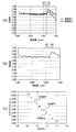
図4は、条件(1)の値に対するスポットサイズの変化を説明するためのグラフである。図4(a),(b)の縦軸は、透過率(正規化のため単位無し)を、横軸は、瞳座標(単位:mm)を、それぞれ示す。図4(c)の縦軸は、光ディスクD1の記録面に形成されるスポットのサイズ(単位:μm)を、横軸は、条件(1)の値を、それぞれ示す。なお、スポットサイズは、周辺側透過光量と中央側透過光量とのバランスが取れているときのサイズほど理想的である。図4(c)中、条件(1)の値が1に近いスポットサイズほど理想的である。まず、条件(1)を満たす3例に着目して説明をする。 FIG. 4 is a graph for explaining the change of the spot size with respect to the value of the condition (1). 4A and 4B, the vertical axis represents transmittance (no unit for normalization), and the horizontal axis represents pupil coordinates (unit: mm). In FIG. 4C, the vertical axis represents the size (unit: μm) of the spot formed on the recording surface of the optical disc D1, and the horizontal axis represents the value of the condition (1). Note that the spot size is more ideal as the spot size is balanced between the peripheral side transmitted light amount and the center side transmitted light amount. In FIG. 4C, the spot size where the value of the condition (1) is close to 1 is ideal. First, description will be given focusing on three examples that satisfy the condition (1).
実施例1は、有効光束径内の段差総量に対する第二領域RE内の段差総量の割合が多く、図4(a)に示されるように、第二領域RE内での透過率が低い。実施例2は、有効光束径内の段差総量に対する第二領域RE内の段差総量の割合が実施例1よりも少なく、図4(a)に示されるように、第二領域RE内での透過率が実施例1よりも高い。実施例3は、有効光束径内の段差総量に対する第二領域RE内の段差総量の割合が実施例2よりも少なく、図4(b)に示されるように、第二領域RE内での透過率が実施例2よりも高い。実施例2は、実施例1と比べて、周辺側透過光量が中央側透過光量に対して多いから、超解像の影響を実施例1よりも受ける。また、実施例3は、実施例2と比べて、周辺側透過光量が中央側透過光量に対して多いから、超解像の影響を実施例2よりも受ける。そのため、図4(c)に示されるように、スポットが実施例3、実施例2、実施例1の順に小さい。図4の例によれば、スポットは、条件(1)の値が大きいほど絞られる。しかし、条件(1)を満たす限りは、過剰に絞られることがなく、理想的なサイズに近い。 In Example 1, the ratio of the total amount of steps in the second region RE to the total amount of steps in the effective beam diameter is large, and the transmittance in the second region RE is low as shown in FIG. In Example 2, the ratio of the total amount of steps in the second region RE to the total amount of steps in the effective beam diameter is smaller than that in Example 1, and as shown in FIG. 4A, the transmission in the second region RE is performed. The rate is higher than Example 1. In Example 3, the ratio of the total amount of steps in the second region RE to the total amount of steps in the effective light beam diameter is smaller than that in Example 2, and as shown in FIG. 4B, transmission in the second region RE is performed. The rate is higher than Example 2. The second embodiment is more affected by super-resolution than the first embodiment because the peripheral transmitted light amount is greater than the central transmitted light amount compared to the first embodiment. Further, compared to the second embodiment, the third embodiment is more affected by super-resolution than the second embodiment because the peripheral-side transmitted light amount is larger than the central-side transmitted light amount. Therefore, as shown in FIG. 4C, the spots are smaller in the order of Example 3, Example 2, and Example 1. According to the example of FIG. 4, the spot is narrowed as the value of the condition (1) increases. However, as long as the condition (1) is satisfied, it is not excessively narrowed and is close to an ideal size.
図4(c)に示される15例は、何れも条件(1)を満たしており、スポットサイズが0.384〜0.401の範囲に収まっている。各実施例は、理想的なスポットサイズ(条件(1)の値が1であるときのスポットサイズであり、約0.395μm)と比べても+1.5%程度〜−3.0%程度の範囲に収まる。そのため、光ディスクD1に対する情報の記録又は再生が依然として良好に行われることが分かる。なお、スポットサイズが理想サイズに対して大きい場合、理想サイズに対して小さい場合と比べてジッター等の悪影響が大きい。そのため、条件(1)は、許容する理想と現実のスポットサイズ差が、スポットサイズが大きい場合の方が厳しくなる(小さく)ように設定されている。 All the 15 examples shown in FIG. 4C satisfy the condition (1), and the spot size is in the range of 0.384 to 0.401. Each example is about + 1.5% to about −3.0% compared to the ideal spot size (the spot size when the value of the condition (1) is 1 and about 0.395 μm). Fits in range. Therefore, it can be seen that information recording or reproduction with respect to the optical disc D1 is still performed satisfactorily. Note that when the spot size is larger than the ideal size, adverse effects such as jitter are larger than when the spot size is smaller than the ideal size. Therefore, the condition (1) is set such that the difference between the ideal and actual spot size to be allowed becomes stricter (smaller) when the spot size is larger.
条件(1)は、次の条件(2)
0.80 < ηout /ηin < 1.45 ・・・ (2)
に置き換えることもできる。ηoutは、第二領域REにおける段差ダレを含めた光利用効率である。説明を加えると、ηoutは、回折効率とダレによる損失を考慮した数値であって、第二領域REにおいて段差構造を持たない形状とした場合の透過率に対する、第二領域REにおいて段差構造を持つ場合の透過率の割合である。
Condition (1) is the following condition (2)
0.80 <ηout / ηin <1.45 (2)
Can also be replaced. ηout is the light use efficiency including the step sag in the second region RE. In addition, ηout is a numerical value that takes into account the diffraction efficiency and loss due to sagging, and has a step structure in the second region RE with respect to the transmittance when the second region RE has a shape without a step structure. It is the ratio of the transmittance in the case.
また、第一領域RCにおけるブレーズ波長λB1(単位:nm)を適切に設定することによってスポット形状の最適化だけでなく、それぞれの光ディスクにおける透過光量のバランスを取ることが可能である。下記の表1は、ブレーズ波長λB1と、第一領域RCにおけるレーザー光束L1の回折効率(表1中BD)及び第一領域RCにおけるレーザー光束L2の回折効率(表1中DVD)との関係を示す。表1に示されるように、ブレーズ波長λB1を波長λ1に近付けるほどレーザー光束L1の回折効率が大きくなる。一方、ブレーズ波長λB1を波長λ2に近付けるほどレーザー光束L2の回折効率が小さくなるため、中央側透過光量が減少する。 In addition, by appropriately setting the blaze wavelength λB1 (unit: nm) in the first region RC, not only the spot shape can be optimized, but also the amount of transmitted light in each optical disk can be balanced. Table 1 below shows the relationship between the blaze wavelength λB1, the diffraction efficiency of the laser beam L1 in the first region RC (BD in Table 1), and the diffraction efficiency of the laser beam L2 in the first region RC (DVD in Table 1). Show. As shown in Table 1, the diffraction efficiency of the laser beam L1 increases as the blaze wavelength λB1 approaches the wavelength λ1. On the other hand, the closer the blaze wavelength λB1 is to the wavelength λ2, the smaller the diffraction efficiency of the laser beam L2, so that the transmitted light amount on the center side decreases.
周辺側透過光量と中央側透過光量とのバランスを取り、超解像によるスポット形状への影響を軽減させるためには、中央側透過光量を増加させて周辺側透過光量に近付けることが望ましい。但し、中央側透過光量を増加させすぎると、第一領域RCにおけるレーザー光束L2の回折効率が低下するという問題が生じる。そこで、ブレーズ波長λB1は、次の条件(3)を満たす範囲で設定されている。
450≦λB1≦530・・・(3)
In order to balance the peripheral transmitted light amount and the central transmitted light amount and to reduce the influence of the super-resolution on the spot shape, it is desirable to increase the central transmitted light amount so as to approach the peripheral transmitted light amount. However, if the center side transmitted light amount is excessively increased, there arises a problem that the diffraction efficiency of the laser beam L2 in the first region RC is lowered. Therefore, the blaze wavelength λB1 is set in a range that satisfies the following condition (3).
450 ≦ λB1 ≦ 530 (3)
条件(3)を満たすことにより、レーザー光束L1、L2の何れの使用時においても65%以上の回折効率が確保される(表1参照)。条件(3)の下限を下回る場合、第一領域RCにおけるレーザー光束L2の回折効率が低すぎて、光ディスクD2に対する情報の記録又は再生が良好に行われない。条件(3)の上限を上回る場合は、第一領域RCにおけるレーザー光束L1の回折効率が低すぎて、光ディスクD1に対する情報の記録又は再生が良好に行われない。 Satisfying the condition (3) ensures a diffraction efficiency of 65% or more when using either the laser beam L1 or L2 (see Table 1). If the lower limit of the condition (3) is not reached, the diffraction efficiency of the laser beam L2 in the first region RC is too low, and information recording or reproduction on the optical disc D2 is not performed well. When exceeding the upper limit of the condition (3), the diffraction efficiency of the laser beam L1 in the first region RC is too low, and information recording or reproduction on the optical disc D1 is not performed well.
対物レンズ10は、第二領域REにおけるブレーズ波長をλB2(単位:nm)と定義した場合に、次の条件(4)
390<λB2<420・・・(4)
を満たすように構成される。
The
390 <λB2 <420 (4)
Configured to meet.
条件(4)を満たすことにより、光ディスクD1専用領域である第二領域REでレーザー光束L1の回折効率がほぼ100%になる。条件(4)を外れると、レーザー光束L1の回折効率の低下が顕著である。この場合、周辺側透過光量と中央側透過光量とのバランスを保つためには、周辺側透過光量の低下に合わせて中央側透過光量も低下させる必要がある。しかし、中央側透過光量も低下させると、光ディスクD1に対する情報の記録又は再生に必要な光量が不足するため、望ましくない。 By satisfying the condition (4), the diffraction efficiency of the laser light beam L1 becomes almost 100% in the second region RE that is the region dedicated to the optical disc D1. If the condition (4) is not satisfied, the diffraction efficiency of the laser beam L1 is significantly reduced. In this case, in order to maintain the balance between the peripheral-side transmitted light amount and the central-side transmitted light amount, it is necessary to reduce the central-side transmitted light amount as the peripheral-side transmitted light amount decreases. However, if the transmitted light amount on the center side is also reduced, the amount of light necessary for recording or reproducing information on the optical disc D1 is insufficient, which is not desirable.
対物レンズ10は、レーザー光束L1に対する開口数をNA1’と定義し、レーザー光束L2に対する開口数をNA2’と定義した場合に、次の条件(5)、(6)、
0.78<NA1’<0.90・・・(5)
0.58<NA2’<0.68・・・(6)
を満たすように構成される。すなわち、対物レンズ10のNA1’、NA2’は、光ディスクD1、D2に対する情報の記録又は再生に好適な値である。
When the numerical aperture for the laser beam L1 is defined as NA1 ′ and the numerical aperture for the laser beam L2 is defined as NA2 ′, the
0.78 <NA1 '<0.90 (5)
0.58 <NA2 ′ <0.68 (6)
Configured to meet. That is, NA1 ′ and NA2 ′ of the
対物レンズ10は、超解像によるスポット形状への影響をより一層軽減するためには、次の条件(7)
0.85 < ((Sout-Sd)/Sout)2/ηin < 1.15 ・・・ (7)
を満たす構成であることが望ましい。この条件(7)は、次の条件(8)
0.85 < ηout/ηin < 1.15 ・・・ (8)
に置き換えることもできる。
In order to further reduce the influence of the super-resolution on the spot shape, the
0.85 <((Sout−Sd) / Sout) 2 /ηin<1.15 (7)
It is desirable that the configuration satisfies the above. This condition (7) is the following condition (8)
0.85 <ηout / ηin <1.15 (8)
Can also be replaced.
次に、これまで説明した対物レンズ10を搭載する光情報記録再生装置100の具体的実施例を、15例説明する。各具体的実施例1〜15の光情報記録再生装置100は、図1に示される概略構成を有する。実施例1〜15の対物レンズ10は、図2に示される概略構成を有し、第一面10aの各段差には図3に示すダレが生じているものとする。実施例1〜15は、図4(c)に示した15例に対応する。なお、実施例1〜15の各数値データから再現される対物レンズ10の形状の違いは、本件願書に添付可能な図面の縮尺では現れない微差に過ぎない。よって、実施例1〜15の対物レンズ10の構成図は、図2を参照し、本件願書への添付を省略する。
Next, 15 specific examples of the optical information recording / reproducing
実施例1の光情報記録再生装置100に搭載される対物レンズ10の仕様、具体的には、使用波長、焦点距離、NA、倍率は、表2に示される。なお、実施例1の各表についての説明は、実施例1以外の他の実施例で提示される各表においても適用される。
Table 2 shows the specifications of the
表2中、倍率の値が示すように、光情報記録再生装置100では、何れの光ディスク使用時であっても、レーザー光束は、平行光束として対物レンズ10に入射する。これにより、トラッキングした際における軸外収差の発生が有効に避けられる。光情報記録再生装置100の各光ディスクD1、D2使用時における具体的数値構成は、表3に示される。
As shown by the magnification value in Table 2, in the optical information recording / reproducing
表3中、面番号1−1は、対物レンズ10の第一面10aの第一領域RCを、面番号1−2は、第一面10aの第二領域REを、面番号2は、対物レンズ10の第二面10bを、面番号3は、対象となる光ディスクの保護層表面を、面番号4は、対象となる光ディスクの記録面を、それぞれ示す。「r」は、光学部材の各面の曲率半径(単位:mm)を、「d(406nm)」は、波長λ1に対する光学部材厚又は光学部材間隔(単位:mm)を、「n(406nm)」は、波長λ1に対する光学部材の屈折率を、「d(660nm)」は、波長λ2に対する光学部材厚又は光学部材間隔(単位:mm)を、「n(660nm)」は、波長λ2に対する光学部材の屈折率を、それぞれ示す。なお、非球面素子におけるrは、光軸上での曲率半径を示す。
In Table 3, surface number 1-1 is the first region RC of the
第一領域RC(面番号1−1)、第二領域RE(面番号1−2)、第二面10b(面番号2)は、非球面である。各非球面形状は、光ディスクD1及びD2の記録又は再生に最適に設計されている。各非球面形状を規定する円錐係数κ、非球面係数A4、A6、・・・は、表4に示される。各表における表記Eは、10を基数、Eの右の数字を指数とする累乗を表している。
The first region RC (surface number 1-1), the second region RE (surface number 1-2), and the
第一領域RC(面番号1−1)、第二領域RE(面番号1−2)には、輪帯構造が設けられている。この光路差関数φ(h)を規定する各係数は、表5に示される。 An annular structure is provided in the first region RC (surface number 1-1) and the second region RE (surface number 1-2). Table 5 shows the coefficients that define the optical path difference function φ (h).
表5中、回折次数「1/1」は、第一領域RCで回折効率が最大となるレーザー光束L1、L2の回折次数が共に1次であることを示す。回折次数「1」は、第二領域REで回折効率が最大となるレーザー光束L1の回折次数が1次であることを示す。 In Table 5, the diffraction order “1/1” indicates that both of the diffraction orders of the laser beams L1 and L2 having the maximum diffraction efficiency in the first region RC are the first order. The diffraction order “1” indicates that the diffraction order of the laser beam L1 having the maximum diffraction efficiency in the second region RE is the first order.
第一領域RC、第二領域REの各領域に形成される輪帯構造の具体的構成は、表6に示される。表6中、輪帯構造を構成する各輪帯の番号は、光軸側から順に振られている。番号1〜26の段差位置に対応する段差は、第一領域RCに形成された段差であり、番号27〜83の段差位置に対応する段差は、第二領域REに形成された段差である。 Table 6 shows specific configurations of the annular zone structure formed in each of the first region RC and the second region RE. In Table 6, the numbers of the annular zones constituting the annular zone structure are assigned in order from the optical axis side. The steps corresponding to the step positions with numbers 1 to 26 are steps formed in the first region RC, and the steps corresponding to the step positions with numbers 27 to 83 are steps formed in the second region RE.
実施例2の光情報記録再生装置100に搭載される対物レンズ10の仕様は表7に、光情報記録再生装置100の各光ディスクD1、D2使用時における具体的数値構成は表8に、非球面形状を規定する各係数は表9に、光路差関数φ(h)を規定する各係数は表10に、各領域の輪帯構造の具体的構成は表11に、それぞれ示される。表11中、番号1〜15の段差位置に対応する段差は、第一領域RCに形成された段差であり、番号16〜32の段差位置に対応する段差は、第二領域REに形成された段差である。
Table 7 shows the specifications of the
実施例3の光情報記録再生装置100に搭載される対物レンズ10の仕様は表12に、光情報記録再生装置100の各光ディスクD1、D2使用時における具体的数値構成は表13に、非球面形状を規定する各係数は表14に、光路差関数φ(h)を規定する各係数は表15に、各領域の輪帯構造の具体的構成は表16に、それぞれ示される。表16中、番号1〜14の段差位置に対応する段差は、第一領域RCに形成された段差であり、番号15〜19の段差位置に対応する段差は、第二領域REに形成された段差である。
Table 12 shows the specifications of the
以上説明した実施例1〜3に実施例4〜15、比較例1、2を加えた17例の光情報記録再生装置100を用いて各光ディスクD1、D2に対する情報の記録又は再生を行った際の光学性能を検証する。実施例4〜7の対物レンズ10は、実施例1の対物レンズ10と段差位置が同一で、第一領域RCのブレーズ波長のみ異なるため、段差高さDが異なる。実施例8〜11の対物レンズ10は、実施例2の対物レンズ10と段差位置が同一で、第一領域RCのブレーズ波長のみ異なるため、段差高さDが異なる。実施例12〜15の対物レンズ10は、実施例3の対物レンズ10と段差位置が同一で、第一領域RCのブレーズ波長のみ異なるため、段差高さDが異なる。比較例1、2の対物レンズはそれぞれ、輪帯構造を規定するブレーズ波長λB1が実施例1、2の対物レンズ10と異なる。
When information is recorded or reproduced on each of the optical discs D1 and D2 by using the optical information recording / reproducing
表17は、実施例1〜15、比較例1、2に関する各条件(1)〜(8)の値、及び光ディスクD1の記録面上に形成されるスポットのサイズを示す表である。図5(a)、(b)はそれぞれ、実施例1(又は実施例4〜7の何れか)において光ディスクD1、D2を使用した時の球面収差を示す図である。図6(a)、(b)はそれぞれ、実施例2(又は実施例8〜11の何れか)において光ディスクD1、D2を使用した時の球面収差を示す図である。図7(a)、(b)はそれぞれ、実施例3(又は実施例12〜15の何れか)において光ディスクD1、D2を使用した時の球面収差を示す図である。図5〜7の各図の縦軸は入射瞳座標を、横軸は球面収差量(単位:λrms)を示す。また、図5(a)、図6(a)、図7(a)中、実線、点線、一点鎖線はそれぞれ、レーザー光束L1の波長λ1が406nm、411nm、401nmである時の球面収差を示す。図5(b)、図6(b)、図7(b)中、実線、点線、一点鎖線はそれぞれ、レーザー光束L2の波長λ2が662nm、667nm、657nmである時の球面収差を示す。 Table 17 is a table showing the values of the conditions (1) to (8) regarding Examples 1 to 15 and Comparative Examples 1 and 2, and the size of the spot formed on the recording surface of the optical disc D1. FIGS. 5A and 5B are diagrams showing spherical aberration when the optical discs D1 and D2 are used in Example 1 (or any one of Examples 4 to 7), respectively. FIGS. 6A and 6B are diagrams showing spherical aberration when the optical discs D1 and D2 are used in Example 2 (or any of Examples 8 to 11), respectively. FIGS. 7A and 7B are diagrams showing spherical aberration when the optical discs D1 and D2 are used in Example 3 (or any one of Examples 12 to 15), respectively. 5 to 7, the vertical axis represents the entrance pupil coordinates, and the horizontal axis represents the spherical aberration amount (unit: λrms). In FIGS. 5A, 6A, and 7A, the solid line, the dotted line, and the alternate long and short dash line indicate the spherical aberration when the wavelength λ1 of the laser beam L1 is 406 nm, 411 nm, and 401 nm, respectively. . In FIG. 5B, FIG. 6B, and FIG. 7B, the solid line, the dotted line, and the alternate long and short dash line indicate the spherical aberration when the wavelength λ2 of the laser beam L2 is 662, 667, and 657 nm, respectively.
表17に示されるように、比較例1又は比較例2の構成では、条件(1)が満たされない。具体的には、比較例1は、条件(1)の下限を下回るため、第二領域REの透過光量が非常に少なくなり、第二領域REがレーザー光束L1に対して実質的に開口制限機能を持つ領域として作用する。そのため、NAが変化して、光ディスクD1の記録面に良好なスポットが形成されない。比較例2は、条件(1)の上限を上回るため、第二領域REの透過光量が第一領域RCの透過光量と比べて過剰である。よって、超解像の影響が避けられず、第一の光ディスクの記録面上でスポットが絞られすぎる。これに対して、実施例1〜15の構成では、表17に示されるように、条件(1)が満たされる。そのため、実施例1〜15では、図5〜7に示されるように、何れの光ディスク使用時にも球面収差が良好に補正されつつ、周辺側透過光量と中央側透過光量とのバランスがとれる。そのため、表17又は図4(c)に示されるように、理想レンズの場合(0.395μm)とほぼ同じサイズのスポットが光ディスクD1の記録面上に形成されて、光ディスクD1とD2の両規格に対する情報の記録又は再生が良好に行われる。なお、実施例1〜15では、更に、条件(2)〜(6)も満たされる。実施例1、2、5、6、8、9、14、15においては、条件(7)、(8)が更に満たされる。よって、実施例1〜15では、各条件を満たすことによる更なる効果が奏される。 As shown in Table 17, in the configuration of Comparative Example 1 or Comparative Example 2, the condition (1) is not satisfied. Specifically, since the comparative example 1 is below the lower limit of the condition (1), the amount of light transmitted through the second region RE is very small, and the second region RE substantially functions as an aperture limit with respect to the laser beam L1. Acts as an area with For this reason, the NA changes and a good spot is not formed on the recording surface of the optical disc D1. Since the comparative example 2 exceeds the upper limit of the condition (1), the transmitted light amount in the second region RE is excessive as compared with the transmitted light amount in the first region RC. Therefore, the influence of super-resolution is unavoidable, and the spot is too narrow on the recording surface of the first optical disc. On the other hand, in the configurations of Examples 1 to 15, as shown in Table 17, the condition (1) is satisfied. Therefore, in Examples 1 to 15, as shown in FIGS. 5 to 7, the spherical aberration is well corrected when any optical disk is used, and the peripheral transmitted light amount and the central transmitted light amount are balanced. Therefore, as shown in Table 17 or FIG. 4C, a spot having the same size as that of the ideal lens (0.395 μm) is formed on the recording surface of the optical disk D1, and both standards of the optical disks D1 and D2 are used. Recording or reproduction of information is performed satisfactorily. In Examples 1 to 15, the conditions (2) to (6) are also satisfied. In Examples 1, 2, 5, 6, 8, 9, 14, and 15, the conditions (7) and (8) are further satisfied. Therefore, in Examples 1-15, the further effect by satisfy | filling each condition is show | played.
また、実施例1〜15において対物レンズ10は、第二領域REに段差を多数設けることによって周辺側透過光量を減じつつも回折作用を強めているため、温度変化時に発生する球面収差が良好に補正される。具体的には、レーザー光束L1の温度変化に伴う球面収差の変動量が、実施例1、4〜7では−0.011λrms/50℃に、実施例2、8〜11では−0.153λrms/50℃に、それぞれ抑えられている。実施例3、12〜15では−0.159λrms/50℃に、それぞれ抑えられている。
In the first to fifteenth embodiments, the
また、実施例1〜15において段差のダレΔhを段差高さDと同等と考えているが、成形条件等によって段差のダレΔhが変化した場合においても、条件(1)又は(2)を満たすことで本発明の目的は達成される。更に、条件(7)又は(8)も満たせば更なる効果が奏される。また、通常の成形条件の範囲内で段差のダレΔhは段差高さDの0.3倍から2倍程度まで変化する可能性がある。 Further, in Examples 1 to 15, the step sagging Δh is considered to be equivalent to the step height D, but the condition (1) or (2) is satisfied even when the step sagging Δh changes due to molding conditions or the like. Thus, the object of the present invention is achieved. Furthermore, if the condition (7) or (8) is also satisfied, further effects are achieved. Further, the step sagging Δh may vary from 0.3 times to about twice the step height D within the range of normal molding conditions.
以上が本発明の実施形態の説明である。本発明は、上記の構成に限定されるものではなく、本発明の技術的思想の範囲において様々な変形が可能である。 The above is the description of the embodiment of the present invention. The present invention is not limited to the above-described configuration, and various modifications can be made within the scope of the technical idea of the present invention.
10 対物レンズ
21 BD用モジュール
22 DVD用モジュール
23 ビームコンバイナ
24 コリメートレンズ
100 光情報記録再生装置
DESCRIPTION OF
Claims (12)
前記第一の波長をλ1(単位:nm)と定義し、前記第二の波長をλ2(単位:nm)と定義した場合に、
380<λ1<420
640<λ2<700
であり、
前記第一の波長λ1の光束を用いて情報の記録又は再生が行われる前記第一の光ディスクの保護層をt1(単位:mm)と定義し、前記第二の波長λ2の光束を用いて情報の記録又は再生が行われる前記第二の光ディスクの保護層をt2(単位:mm)と定義した場合に、
0.05<t1<0.15
0.50<t2<0.70
であり、
前記第一の光ディスクに対する情報の記録又は再生に必要な開口数をNA1と定義し、前記第二の光ディスクに対する情報の記録又は再生に必要な開口数をNA2と定義した場合に、
NA1>NA2
であり、
光源側の面又は前記光ディスク側の面の少なくとも一方に、
前記第一の波長λ1の光束を前記第一の光ディスクの記録面上に、前記第二の波長λ2の光束を前記第二の光ディスクの記録面上に、それぞれ収束させる第一領域であって、光軸を中心とする同心状の複数の屈折面に分割され、互いに隣り合う該屈折面の境界において入射光束に対して光路長差を付与する第一の段差を有し、該第一の段差を透過した第一の波長λ1、第二の波長λ2の各光束使用時における回折効率が最大となる回折次数が共に1次である第一領域と、
前記第一の波長λ1の光束を前記第一の光ディスクの記録面上に収束させて、前記第二の波長λ2の光束を前記第一、前記第二の光ディスクの何れの記録面上にも収束させない、前記第一領域の外側に配置された第二領域であって、前記光軸を中心とする同心状の複数の屈折面に分割され、互いに隣り合う該屈折面の境界において入射光束に対して光路長差を付与する第二の段差を有する第二領域と、
を有し、
前記第二の段差には、前記第二領域における前記第一の波長λ1の光束に対する光利用効率に影響を与えるダレが形成され、
前記第一領域における回折効率をηinと定義し、前記第二領域の光軸と垂直な平面での投影面積をSoutと定義し、該第二領域のうち前記ダレが形成された領域の光軸と垂直な平面での投影面積をSdと定義した場合に、次の条件(1)
0.80 < ((Sout-Sd)/Sout)2/ηin < 1.45 ・・・ (1)
を満たすことを特徴とする光情報記録再生装置用対物レンズ。 By using substantially parallel light beams having first and second wavelengths emitted from a predetermined light source for each of the first and second optical discs having different recording densities, information can be recorded or reproduced on each optical disc. In an objective lens for an optical information recording / reproducing apparatus mounted on an optical information recording / reproducing apparatus to perform,
When the first wavelength is defined as λ1 (unit: nm) and the second wavelength is defined as λ2 (unit: nm),
380 <λ1 <420
640 <λ2 <700
And
The protective layer of the first optical disk on which information is recorded or reproduced using the light beam having the first wavelength λ1 is defined as t1 (unit: mm), and information using the light beam having the second wavelength λ2 is defined. When the protective layer of the second optical disc on which recording or reproduction is performed is defined as t2 (unit: mm),
0.05 <t1 <0.15
0.50 <t2 <0.70
And
When the numerical aperture necessary for recording or reproducing information on the first optical disc is defined as NA1, and the numerical aperture necessary for recording or reproducing information on the second optical disc is defined as NA2,
NA1> NA2
And
At least one of the light source side surface and the optical disc side surface,
A first region for converging the light beam having the first wavelength λ1 on the recording surface of the first optical disc and the light beam having the second wavelength λ2 on the recording surface of the second optical disc, The first step is divided into a plurality of concentric refracting surfaces with the optical axis as the center, and has a first step that gives an optical path length difference to the incident light flux at the boundary between the refracting surfaces adjacent to each other. A first region in which the diffraction orders at which the diffraction efficiency is maximized when using each of the light beams having the first wavelength λ1 and the second wavelength λ2 that are transmitted through
The light beam having the first wavelength λ1 is converged on the recording surface of the first optical disk, and the light beam having the second wavelength λ2 is converged on either the recording surface of the first or second optical disk. A second region disposed outside the first region, which is divided into a plurality of concentric refracting surfaces centered on the optical axis, and incident light fluxes at the boundary between the refracting surfaces adjacent to each other. A second region having a second step for providing an optical path length difference,
Have
In the second step, a sagging that affects the light use efficiency with respect to the light beam having the first wavelength λ1 in the second region is formed,
The diffraction efficiency in the first region is defined as ηin, the projected area in a plane perpendicular to the optical axis of the second region is defined as Sout, and the optical axis of the region where the sagging is formed in the second region When the projected area on a plane perpendicular to the plane is defined as Sd, the following condition (1)
0.80 <((Sout−Sd) / Sout) 2 /ηin<1.45 (1)
An objective lens for an optical information recording / reproducing apparatus, characterized in that:
前記第一の波長をλ1(単位:nm)と定義し、前記第二の波長をλ2(単位:nm)と定義した場合に、
380<λ1<420
640<λ2<700
であり、
前記第一の波長λ1の光束を用いて情報の記録又は再生が行われる前記第一の光ディスクの保護層をt1(単位:mm)と定義し、前記第二の波長λ2の光束を用いて情報の記録又は再生が行われる前記第二の光ディスクの保護層をt2(単位:mm)と定義した場合に、
0.05<t1<0.15
0.50<t2<0.70
であり、
前記第一の光ディスクに対する情報の記録又は再生に必要な開口数をNA1と定義し、前記第二の光ディスクに対する情報の記録又は再生に必要な開口数をNA2と定義した場合に、
NA1>NA2
であり、
光源側の面又は前記光ディスク側の面の少なくとも一方に、
前記第一の波長λ1の光束を前記第一の光ディスクの記録面上に、前記第二の波長λ2の光束を前記第二の光ディスクの記録面上に、それぞれ収束させる第一領域であって、光軸を中心とする同心状の複数の屈折面に分割され、互いに隣り合う該屈折面の境界において入射光束に対して光路長差を付与する第一の段差を有し、該第一の段差を透過した第一の波長λ1、第二の波長λ2の各光束使用時における回折効率が最大となる回折次数が共に1次である第一領域と、
前記第一の波長λ1の光束を前記第一の光ディスクの記録面上に収束させて、前記第二の波長λ2の光束を前記第一、前記第二の光ディスクの何れの記録面上にも収束させない、前記第一領域の外側に配置された第二領域であって、前記光軸を中心とする同心状の複数の屈折面に分割され、互いに隣り合う該屈折面の境界において入射光束に対して光路長差を付与する第二の段差を有する第二領域と、
を有し、
前記第二の段差には、前記第二領域における前記第一の波長λ1の光束に対する光利用効率に影響を与えるダレが形成され、
前記第一領域における回折効率をηinと定義し、前記第二領域における前記ダレの影響を含んだ光利用効率をηoutと定義した場合に、次の条件(2)
0.80 < ηout/ηin < 1.45 ・・・ (2)
を満たすことを特徴とする光情報記録再生装置用対物レンズ。 By using substantially parallel light beams having first and second wavelengths emitted from a predetermined light source for each of the first and second optical discs having different recording densities, information can be recorded or reproduced on each optical disc. In an objective lens for an optical information recording / reproducing apparatus mounted on an optical information recording / reproducing apparatus to perform,
When the first wavelength is defined as λ1 (unit: nm) and the second wavelength is defined as λ2 (unit: nm),
380 <λ1 <420
640 <λ2 <700
And
The protective layer of the first optical disk on which information is recorded or reproduced using the light beam having the first wavelength λ1 is defined as t1 (unit: mm), and information using the light beam having the second wavelength λ2 is defined. When the protective layer of the second optical disc on which recording or reproduction is performed is defined as t2 (unit: mm),
0.05 <t1 <0.15
0.50 <t2 <0.70
And
When the numerical aperture necessary for recording or reproducing information on the first optical disc is defined as NA1, and the numerical aperture necessary for recording or reproducing information on the second optical disc is defined as NA2,
NA1> NA2
And
At least one of the light source side surface and the optical disc side surface,
A first region for converging the light beam having the first wavelength λ1 on the recording surface of the first optical disc and the light beam having the second wavelength λ2 on the recording surface of the second optical disc, The first step is divided into a plurality of concentric refracting surfaces with the optical axis as the center, and has a first step that gives an optical path length difference to the incident light flux at the boundary between the refracting surfaces adjacent to each other. A first region in which the diffraction orders at which the diffraction efficiency is maximized when using each of the light beams having the first wavelength λ1 and the second wavelength λ2 that are transmitted through
The light beam having the first wavelength λ1 is converged on the recording surface of the first optical disk, and the light beam having the second wavelength λ2 is converged on either the recording surface of the first or second optical disk. A second region disposed outside the first region, which is divided into a plurality of concentric refracting surfaces centered on the optical axis, and incident light fluxes at the boundary between the refracting surfaces adjacent to each other. A second region having a second step for providing an optical path length difference,
Have
In the second step, a sagging that affects the light use efficiency with respect to the light beam having the first wavelength λ1 in the second region is formed,
Wherein the diffraction efficiency in the first region is defined as Itain, when you define the ηout the light utilization efficiency including the influence of the sag in the second region, the following conditions (2)
0.80 <ηout / ηin <1.45 (2)
An objective lens for an optical information recording / reproducing apparatus, characterized in that:
請求項1または請求項2に記載の光情報記録再生装置用対物レンズ。The objective lens for an optical information recording / reproducing apparatus according to claim 1 or 2.
450≦λB1≦530・・・(3)
を満たすことを特徴とする、請求項1から請求項3の何れか一項に記載の光情報記録再生装置用対物レンズ。 When the blaze wavelength in the first region is defined as λB1 (unit: nm), the following condition (3)
450 ≦ λB1 ≦ 530 (3)
The objective lens for an optical information recording / reproducing apparatus according to any one of claims 1 to 3, wherein:
390<λB2<420・・・(4)
を満たすことを特徴とする、請求項1から請求項4の何れか一項に記載の光情報記録再生装置用対物レンズ。 When the blaze wavelength in the second region is defined as λB2 (unit: nm), the following condition (4)
390 <λB2 <420 (4)
The objective lens for an optical information recording / reproducing apparatus according to any one of claims 1 to 4 , wherein:
0.78<NA1’<0.90・・・(5)
0.58<NA2’<0.68・・・(6)
を満たすことを特徴とする、請求項1から請求項5の何れか一項に記載の光情報記録再生装置用対物レンズ。 When the numerical aperture for the light beam having the first wavelength λ1 is defined as NA1 ′ and the numerical aperture for the light beam having the second wavelength λ2 is defined as NA2 ′, the following conditions (5), (6)
0.78 <NA1 '<0.90 (5)
0.58 <NA2 ′ <0.68 (6)
The objective lens for an optical information recording / reproducing apparatus according to any one of claims 1 to 5 , wherein:
0.85 < ((Sout-Sd)/Sout)2 /ηin < 1.15 ・・・ (7)
を満たすことを特徴とする、請求項1を引用する請求項3から請求項6の何れか一項に記載の光情報記録再生装置用対物レンズ。 Next condition (7)
0.85 <((Sout−Sd) / Sout) 2 / ηin <1.15 (7)
The objective lens for an optical information recording / reproducing apparatus according to any one of claims 3 to 6 , wherein the objective lens according to claim 1 is cited.
0.85 < ηout/ηin < 1.15 ・・・ (8)
を満たすことを特徴とする、請求項2を引用する請求項3から請求項6の何れか一項に記載の光情報記録再生装置用対物レンズ。 Next condition (8)
0.85 <ηout / ηin <1.15 (8)
The objective lens for an optical information recording / reproducing apparatus according to any one of claims 3 to 6 , wherein the objective lens according to claim 2 is cited.
請求項1から請求項11の何れか一項に記載の光情報記録再生装置用対物レンズと、
前記第一又は前記第二の光ディスクの記録面からの戻り光を検出して所定の信号処理を行う信号処理手段と、
を有することを特徴とする光情報記録再生装置。 By using substantially parallel light beams having first and second wavelengths emitted from a predetermined light source for each of the first and second optical discs having different recording densities, information can be recorded or reproduced on each optical disc. In the optical information recording / reproducing apparatus to perform,
An objective lens for an optical information recording / reproducing apparatus according to any one of claims 1 to 11 ,
Signal processing means for detecting a return light from the recording surface of the first or second optical disc and performing predetermined signal processing;
An optical information recording / reproducing apparatus comprising:
Priority Applications (3)
| Application Number | Priority Date | Filing Date | Title |
|---|---|---|---|
| JP2010178722A JP5584552B2 (en) | 2009-12-21 | 2010-08-09 | Objective lens for optical information recording / reproducing apparatus, and optical information recording / reproducing apparatus |
| US12/972,790 US8107350B2 (en) | 2009-12-21 | 2010-12-20 | Optical information recording/reproducing apparatus and objective lens for the same |
| CN201010597882.6A CN102103871B (en) | 2009-12-21 | 2010-12-21 | Optical information recording/reproducing apparatus and objective lens for the same |
Applications Claiming Priority (3)
| Application Number | Priority Date | Filing Date | Title |
|---|---|---|---|
| JP2009289228 | 2009-12-21 | ||
| JP2009289228 | 2009-12-21 | ||
| JP2010178722A JP5584552B2 (en) | 2009-12-21 | 2010-08-09 | Objective lens for optical information recording / reproducing apparatus, and optical information recording / reproducing apparatus |
Publications (2)
| Publication Number | Publication Date |
|---|---|
| JP2011150773A JP2011150773A (en) | 2011-08-04 |
| JP5584552B2 true JP5584552B2 (en) | 2014-09-03 |
Family
ID=44150867
Family Applications (1)
| Application Number | Title | Priority Date | Filing Date |
|---|---|---|---|
| JP2010178722A Expired - Fee Related JP5584552B2 (en) | 2009-12-21 | 2010-08-09 | Objective lens for optical information recording / reproducing apparatus, and optical information recording / reproducing apparatus |
Country Status (3)
| Country | Link |
|---|---|
| US (1) | US8107350B2 (en) |
| JP (1) | JP5584552B2 (en) |
| CN (1) | CN102103871B (en) |
Families Citing this family (1)
| Publication number | Priority date | Publication date | Assignee | Title |
|---|---|---|---|---|
| US9633688B2 (en) * | 2013-07-16 | 2017-04-25 | Sharp Kabushiki Kaisha | Reproducing device |
Family Cites Families (17)
| Publication number | Priority date | Publication date | Assignee | Title |
|---|---|---|---|---|
| JP2532818B2 (en) | 1993-02-01 | 1996-09-11 | 松下電器産業株式会社 | Objective lens and optical head device |
| JP3689266B2 (en) * | 1998-06-26 | 2005-08-31 | ペンタックス株式会社 | Objective lens for optical head |
| JP4131366B2 (en) * | 2000-10-30 | 2008-08-13 | コニカミノルタホールディングス株式会社 | Objective lens, optical pickup device and recording / reproducing device |
| JP4610118B2 (en) * | 2001-03-30 | 2011-01-12 | Hoya株式会社 | Objective lens for optical head |
| JP2004101931A (en) * | 2002-09-10 | 2004-04-02 | Konica Minolta Holdings Inc | Objective condensing means and optical pickup device |
| JP2004288346A (en) * | 2002-10-18 | 2004-10-14 | Konica Minolta Holdings Inc | Optical element for optical pickup device, coupling lens, and optical pickup device |
| US7408866B2 (en) * | 2003-02-14 | 2008-08-05 | Konica Minolta Holdings, Inc. | Objective lens for optical pickup apparatus, optical pickup apparatus and optical information recording reproducing apparatus |
| JP4433818B2 (en) | 2003-02-14 | 2010-03-17 | コニカミノルタホールディングス株式会社 | Objective lens for optical pickup device, optical pickup device and optical information recording / reproducing device |
| JP2004326862A (en) | 2003-04-22 | 2004-11-18 | Konica Minolta Opto Inc | Diffraction optical element used in optical pickup device, optical pickup device and optical information recording and reproducing device |
| EP1471514A3 (en) * | 2003-04-22 | 2006-10-04 | Konica Minolta Opto, Inc. | Optical pickup device, optical information recording and reproducing apparatus, expander lens, coupling lens and chromatic aberration correcting optical element |
| US6982838B2 (en) * | 2003-06-04 | 2006-01-03 | Pentax Corporation | Objective lens for optical pick-up |
| US7038862B2 (en) * | 2003-06-17 | 2006-05-02 | Pentax Corporation | Objective lens for optical pick-up |
| US6952390B2 (en) * | 2003-06-30 | 2005-10-04 | Konica Minolta Opto, Inc. | Optical pickup apparatus, condensing optical system, and optical element |
| JP3948481B2 (en) * | 2003-08-12 | 2007-07-25 | コニカミノルタオプト株式会社 | Optical pickup device |
| JP4321217B2 (en) * | 2003-10-31 | 2009-08-26 | コニカミノルタオプト株式会社 | Optical element and optical pickup device |
| JP4849979B2 (en) * | 2005-07-12 | 2012-01-11 | Hoya株式会社 | Objective lens for optical information recording / reproducing apparatus and optical information recording / reproducing apparatus |
| JP5199655B2 (en) * | 2007-12-12 | 2013-05-15 | Hoya株式会社 | Objective lens for optical information recording / reproducing apparatus and optical information recording / reproducing apparatus |
-
2010
- 2010-08-09 JP JP2010178722A patent/JP5584552B2/en not_active Expired - Fee Related
- 2010-12-20 US US12/972,790 patent/US8107350B2/en not_active Expired - Fee Related
- 2010-12-21 CN CN201010597882.6A patent/CN102103871B/en not_active Expired - Fee Related
Also Published As
| Publication number | Publication date |
|---|---|
| CN102103871B (en) | 2014-04-16 |
| US20110149712A1 (en) | 2011-06-23 |
| CN102103871A (en) | 2011-06-22 |
| US8107350B2 (en) | 2012-01-31 |
| JP2011150773A (en) | 2011-08-04 |
Similar Documents
| Publication | Publication Date | Title |
|---|---|---|
| JP2011014236A (en) | Objective optical system for optical pickup device, optical pickup device, drive device for optical information recording medium, condensing lens, and optical path integration element | |
| JP4822175B2 (en) | Objective lens, optical pickup device, and optical information recording / reproducing device | |
| JPWO2010013616A1 (en) | Objective lens and optical pickup device | |
| JPWO2008136242A1 (en) | Optical pickup device and objective optical element | |
| JP2015057751A (en) | Objective optical system for optical information recording and reproducing device, and optical information recording and reproducing device | |
| JP2009252309A (en) | Objective lens for optical information recording/reproducing device and optical information recording/reproducing device | |
| JP5013117B2 (en) | Optical pickup device and objective optical element for optical pickup device | |
| JP2005353261A (en) | Optical pickup device | |
| JP2005202998A (en) | Objective lens for optical disc | |
| JP4850013B2 (en) | Optical information recording / reproducing apparatus and objective lens for optical information recording / reproducing apparatus | |
| JP5584552B2 (en) | Objective lens for optical information recording / reproducing apparatus, and optical information recording / reproducing apparatus | |
| JP4828303B2 (en) | Objective lens for optical information recording / reproducing apparatus and optical information recording / reproducing apparatus | |
| JPWO2006121025A1 (en) | Optical pickup device | |
| JP2009070547A (en) | Objective optical system for optical information recording/reproducing device, and optical information recording/reproducing device | |
| JP2007334952A (en) | Objective lens for optical information recording / reproducing device | |
| JP2010153006A (en) | Objective optical element and optical pickup device | |
| JP4849979B2 (en) | Objective lens for optical information recording / reproducing apparatus and optical information recording / reproducing apparatus | |
| JP5300769B2 (en) | Objective lens for optical information recording / reproducing apparatus, and optical information recording / reproducing apparatus | |
| JP5363951B2 (en) | Optical information recording / reproducing apparatus | |
| JP4849905B2 (en) | Optical pickup optical system, objective lens, and optical pickup device | |
| JP2010153016A (en) | Objective lens for optical information recording/reproducing apparatus, optical information recording/reproducing apparatus | |
| JP2008165963A (en) | Objective optical system for optical information recording/reproducing device and optical information recording/reproducing device | |
| JP2008123659A (en) | Objective lens for optical information recording / reproducing apparatus and optical information recording / reproducing apparatus | |
| JP2013109801A (en) | Objective lens for optical pickup device, optical pickup device, and optical information recording/reproducing device | |
| JP2011028808A (en) | Objective lens for optical pickup device, optical pickup device, and optical information recording/reproducing device |
Legal Events
| Date | Code | Title | Description |
|---|---|---|---|
| RD04 | Notification of resignation of power of attorney |
Free format text: JAPANESE INTERMEDIATE CODE: A7424 Effective date: 20130510 |
|
| A621 | Written request for application examination |
Free format text: JAPANESE INTERMEDIATE CODE: A621 Effective date: 20130719 |
|
| A977 | Report on retrieval |
Free format text: JAPANESE INTERMEDIATE CODE: A971007 Effective date: 20131219 |
|
| A131 | Notification of reasons for refusal |
Free format text: JAPANESE INTERMEDIATE CODE: A131 Effective date: 20131224 |
|
| A521 | Written amendment |
Free format text: JAPANESE INTERMEDIATE CODE: A523 Effective date: 20140221 |
|
| TRDD | Decision of grant or rejection written | ||
| A01 | Written decision to grant a patent or to grant a registration (utility model) |
Free format text: JAPANESE INTERMEDIATE CODE: A01 Effective date: 20140702 |
|
| A61 | First payment of annual fees (during grant procedure) |
Free format text: JAPANESE INTERMEDIATE CODE: A61 Effective date: 20140718 |
|
| R150 | Certificate of patent or registration of utility model |
Ref document number: 5584552 Country of ref document: JP Free format text: JAPANESE INTERMEDIATE CODE: R150 |
|
| S111 | Request for change of ownership or part of ownership |
Free format text: JAPANESE INTERMEDIATE CODE: R313113 |
|
| R350 | Written notification of registration of transfer |
Free format text: JAPANESE INTERMEDIATE CODE: R350 |
|
| LAPS | Cancellation because of no payment of annual fees |