JP5584559B2 - Impact rotary tool - Google Patents
Impact rotary tool Download PDFInfo
- Publication number
- JP5584559B2 JP5584559B2 JP2010189992A JP2010189992A JP5584559B2 JP 5584559 B2 JP5584559 B2 JP 5584559B2 JP 2010189992 A JP2010189992 A JP 2010189992A JP 2010189992 A JP2010189992 A JP 2010189992A JP 5584559 B2 JP5584559 B2 JP 5584559B2
- Authority
- JP
- Japan
- Prior art keywords
- anvil
- hammer
- impact
- unit
- hit
- Prior art date
- Legal status (The legal status is an assumption and is not a legal conclusion. Google has not performed a legal analysis and makes no representation as to the accuracy of the status listed.)
- Active
Links
Images


Landscapes
- Percussive Tools And Related Accessories (AREA)
Description
本発明は、インパクトレンチやインパクトドライバー等の打撃動作を伴って回転駆動を伝達するインパクト回転工具に関するものである。 The present invention relates to an impact rotary tool that transmits rotational drive with an impact operation such as an impact wrench or impact driver.
従来からインパクト回転工具は、駆動源であるモータと、モータにより回転するハンマと、ハンマに打撃されて回転を伝達するアンビルと、アンビルの回転を出力する出力部と、からなる(例えば、特許文献1等参照)。 Conventionally, an impact rotary tool includes a motor that is a driving source, a hammer that is rotated by the motor, an anvil that is struck by the hammer and transmits the rotation, and an output unit that outputs the rotation of the anvil (for example, Patent Documents). 1 etc.).
このようなものでは、ハンマが軸方向に移動しながら回転して打撃を行うため、ハンマに衝突されたアンビルには、モータからの回転駆動である回転方向(軸の周方向)の力の他に、軸方向の力も与えられている。そして、この軸方向の力は、出力部に取り付けられた先端工具と、該先端工具により締付けあるいは緩められるネジ等の被締付部材と、の接触部位を振動させるため、工具使用時に騒音を発生させる原因になっている。そのため、特許文献1等では、ハンマを回転させる駆動軸とアンビルの軸方向の隙間に緩衝材を配置して、アンビルが軸方向に振動することを抑制して、先端工具と被締付部材の間から発生する騒音を低減している。
In such a case, since the hammer rotates and strikes while moving in the axial direction, the anvil collided with the hammer has a force in the rotational direction (the circumferential direction of the shaft) that is a rotational drive from the motor. In addition, axial forces are also provided. This axial force vibrates the contact part between the tip tool attached to the output section and the member to be tightened such as a screw that is tightened or loosened by the tip tool, generating noise when using the tool. It is a cause. For this reason, in
しかしながら、これら従来のものでは、軸方向の力により発生する騒音は低減できるが、ハンマとアンビルの衝突時(打撃時)に回転方向の力により発生する騒音(衝突音)を低減できないという問題がある。 However, these conventional devices can reduce the noise generated by the axial force, but cannot reduce the noise (collision sound) generated by the rotational force when the hammer and the anvil collide (when hit). is there.
そこで、この事情に鑑み、打撃時に、回転方向の力により発生する騒音を低減したインパクト回転工具を提供することを課題とした。 Therefore, in view of this situation, an object of the present invention is to provide an impact rotary tool that reduces noise generated by force in the rotational direction at the time of impact.
この課題を解決するために、本発明のインパクト回転工具は、モータを有した駆動部と、前記駆動部の回転駆動を出力する出力部と、前記駆動部の回転駆動を打撃動作を伴って前記出力部に伝達する打撃部と、を有し、前記打撃部が、前記駆動部により回転するハンマと、前記ハンマに打撃される被打撃面を有すると共に前記出力部に回転駆動を伝達するアンビルと、前記被打撃面を覆う粘性流体と、からなる。 In order to solve this problem, an impact rotary tool according to the present invention includes a drive unit having a motor, an output unit that outputs the rotation drive of the drive unit, and the rotation drive of the drive unit with a striking operation. A hammer part that transmits to the output part, and the hammer part has a hammered surface that is struck by the hammer, and an anvil that transmits the rotational drive to the output part. And a viscous fluid covering the hit surface .
そして、前記粘性流体が磁性流体であり、前記磁性流体が前記アンビルに磁気吸着されて前記被打撃面を覆うものであることに特徴を有している。 The viscous fluid is a magnetic fluid, and the magnetic fluid is magnetically attracted to the anvil to cover the hit surface .
このインパクト回転工具として、前記アンビルが永久磁石を有し、前記永久磁石が前記被打撃面に磁極を形成するものであることが好ましい。 As the impact rotating tool, it is preferable that the anvil has a permanent magnet, and the permanent magnet forms a magnetic pole on the hit surface.
このインパクト回転工具として、前記アンビルを磁化するコイルを有し、前記コイルによる磁化で前記被打撃面に磁極を形成するものであることが好ましい。 The impact rotating tool preferably has a coil for magnetizing the anvil and forms a magnetic pole on the hit surface by the magnetization of the coil.
このような構成としたことで、打撃時に、回転方向の力により発生する騒音を低減することができる。 By adopting such a configuration, it is possible to reduce noise generated by force in the rotational direction at the time of impact.
以下、インパクト回転工具の実施形態を図面に基づいて説明する。 Hereinafter, an embodiment of an impact rotary tool will be described based on the drawings.
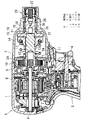
実施形態の一例のインパクト回転工具は、図1に示すように、駆動源であるモータ7が収納された円筒部5と、円筒部5の周面に一端が接続された把持部3と、把持部3の他端に設けられた電源部(特に図示しない)と、からなる。そして、外装は、二つ割りのハウジング1と、両ハウジング1で形成された円筒部5の回転駆動の出力側に取り付けられた筒状のカバー2と、で構成されており、図1は両ハウジング1間の継ぎ目に沿って切断した図である。
As shown in FIG. 1, an impact rotary tool according to an embodiment includes a cylindrical portion 5 in which a
把持部3は、モータ7の回転速度等を操作するトリガスイッチ4と、インパクト回転工具を制御する制御回路(特に図示しない)と、を備えている。そして、電源部は二次電池やバッテリー等を有した電池パックからなり、把持部3に脱着自在で取り付けられている。更に、電源部は制御回路及びモータ7に電力を供給すると共に、電池パックの容量や残量等の情報を制御回路に出力している。なお、電源部は外部の商用電源とインパクト回転工具を電気的に接続する接続コードからなるものであってもよい。
The grip portion 3 includes a
また、円筒部5は、モータ7を有した駆動部6と、駆動部6の回転駆動を出力する出力部25と、駆動部6の回転駆動を打撃動作を伴って出力部25に伝達する打撃部11と、を備えている。駆動部6は、ブラシレス型のモータ7と、モータ7の回転駆動を減速して打撃部11に伝達する減速部9と、を有している。そして、減速部9は、例えば、回転駆動を減速する複数の歯車からなる歯車組と、歯車組を内部に収容したギアケース10と、で構成された遊星減速機構であり、モータ7の回転軸8が歯車組に接続されている。更に、ギアケース10は、円筒部5のハウジング1とカバー2の接続部位に位置して、ハウジング1及びカバー2に固定されており、ギアケース10とカバー2に囲まれた空間には打撃部11及び出力部25が配置されている。
The cylindrical portion 5 includes a
打撃部11は、モータ7によって回転するハンマ14と、ハンマ14に打撃されて回転するアンビル18と、を備えたインパクト機構であり、詳細は後述する。
The striking portion 11 is an impact mechanism including a
出力部25は回転駆動を外部に出力する出力軸26からなり、出力軸26の一端はカバー2を貫通して外部に露出しており、露出した一端(先端)は、先端工具(特に図示しない)を脱着自在に取り付けるチャック27になっている。そのため、出力部25は、打撃部11から伝達された回転駆動によって、チャック27に取り付けられた先端工具を回転させることで、回転駆動を外部に出力している。
The
そして、モータ7の回転軸8の軸芯と、打撃部11のハンマ14及びアンビル18の回転中心と、出力部25の出力軸26の軸芯が、略同一直線上に並んで配置されている。以下、回転軸8等の並ぶ直線を軸方向とし、該軸方向に視た形状を平面視とし、ハンマ14やアンビル18が回転する回転円の円周に沿った方向を回転方向とし、該回転円の中心から外周への径に沿った向きをラジアル方向として、打撃部11の詳細を説明する。
And the axis of the
打撃部11は、図1及び図2に示すように、減速部9から回転駆動が入力される駆動軸12と、駆動軸12により回転するハンマ14と、ハンマ14に打撃されるアンビル18と、駆動軸12とハンマ14を接続するカム部13と、を有している。そして、駆動軸12は、モータ7に近い側の端部がギアケース10を貫通して歯車組に接続されており、他方の端部の外周にハンマ14がカム部13を介して取り付けられている。
As shown in FIGS. 1 and 2, the striking unit 11 includes a
カム部13は、駆動軸12の外周とハンマ14の内周に夫々形成されたカム溝と、カム溝内に配置されたカム球と、からなり、カム球は駆動軸12の回転をハンマ14に伝達すると共にカム溝内を転がり動くことで、ハンマ14を軸方向に移動自在としている。すなわち、ハンマ14はカム部13を介して、駆動軸12の外周で軸方向に移動自在であると共に、駆動軸12に回転させられるものとなっており、ハンマ14は回転と軸方向の移動の両動作を行うことで、アンビル18を打撃する打撃動作を行っている。なお、符号17はハンマ14をアンビル18側に付勢する付勢ばねである。
The cam portion 13 includes cam grooves formed on the outer periphery of the
そして、ハンマ14及びアンビル18は、打撃動作に伴う衝突に耐えられる程度の高い剛性を有した剛性材料で形成されており、剛性材料とは、例えば、鉄やステンレス、あるいはチタン等の金属部材である。なお、高い剛性とは、打撃時の衝突で、ヒビ割れや欠け落ち等の破損や、彎曲や凹み等の形状変形等を生じ難い程度の剛性である。更に、アンビル18は剛性部材のなかでも、強磁性体としての機能を有する金属部材で形成されており、鉄鋼やステンレス等の鉄系部材が好ましい。
The
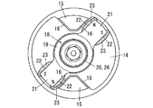
また、ハンマ14はアンビル18に衝突する突出部15を複数(実施例では二つ)備えており、突出部15はハンマ14のアンビル18側の端部から軸方向に突出してハンマ14と一体で設けられている。そして、突出部15は平面視略三角形の角柱状で突出しており、三角形の角の一つをハンマ14の回転中心に向けると共に、残りの角を回転方向に並べて配置されている。更に、平面視において、突出部15は互いにハンマ14の回転中心を基点として点対称で位置しており、角柱の回転方向を向く側面16が、打撃時にアンビル18と接触する打撃面になっている。
The
アンビル18は、図1乃至図3に示すように、ハンマ14及び駆動軸12と略同芯で回転自在となっている。詳しくは、アンビル18の回転中心に略同芯で配置された平面視略環状の本体部19と、突出部15が衝突する平面視矩形状の接触部21と、アンビル18の回転を出力軸26に伝達する伝達軸20と、からなる。
As shown in FIGS. 1 to 3, the
そして、本体部19は接触部21で受けた回転駆動により回転することで、伝達軸20に回転駆動を伝達している。更に、伝達軸20は本体部19と略同芯で本体部19の出力部25側に一端が接続されており、他端が出力軸26と略同芯で出力軸26に接続されており、本体部19からの回転駆動を出力軸26に伝達している。
The
また、接触部21は突出部15と同数で本体部19からラジアル方向に突出して設けられており、接触部21と本体部19は平面視においてアンビル18の回転中心を通る同一直線上に並んでいる。すなわち、アンビル18は本体部19の外周に二つの接触部21を有すると共に、接触部21が本体部19を介して互いに背中を向けて配置されている。そして、接触部21は回転方向を向く両側に夫々、軸方向に平行な側面22を有しており、側面22が突出部15に打撃される被打撃面となっている。
Further, the
また、接触部21は夫々永久磁石になっており、接触部21は各被打撃面に磁極を有しており、被打撃面の磁極は接触部21毎に対をなしている。そして、両接触部21は回転方向で同じ向きを向いた側の被打撃面が、互いに同じ極性の磁極になっており、打撃時に、同じ極性を有した被打撃面が夫々突出部15に衝突されるものとなっている。
Further, each of the
また、打撃部11はカバー2とギアケース10に囲まれた空間内に磁性流体を有しており、磁性流体はオイルシール24によって該空間内に封止されている。そして、オイルシール24は、カバー2とギアケース10の間と、ギアケース10と駆動軸12の間と、伝達軸20とカバー2の間に夫々設けられており、工具外(外装の外側)や減速部9や出力部25に磁性流体が漏れることを抑制している。なお、本例における磁性流体とは、例えば、フェライトやマグネタイト等の強磁性体の微粒子と、油等のベース液と、界面活性剤と、からなる磁性コロイド溶液あるいは、該溶液や上記微粒子を樹脂等でゲル状にした磁性ゲル等である。
The striking portion 11 has a magnetic fluid in a space surrounded by the
そして、空間内に封入された磁性流体の一部は、図2乃至図6に示すように、接触部21の磁気モーメント(磁力)に吸い寄せられて、磁極である被打撃面に付着している。この付着した磁性流体は、磁力によって粘性を増すと共に、被打撃面の略全面を覆い、被打撃面上に粘性流体層23を形成している。そのため、打撃時には、突出部15が磁性流体(粘性流体層23)に接触した後、粘性流体層23を被打撃面と打撃面の間から押し出して、突出部15が接触部21に直接衝突することで、ハンマ14からアンビル18へ回転駆動が伝達されるものとなっている。
A part of the magnetic fluid sealed in the space is attracted to the magnetic moment (magnetic force) of the
詳しくは、ハンマ14が衝突する前では、図4に示すように、磁気吸着された磁性流体(粘性流体層23)が、被打撃面を覆っている。そして、打撃動作によって突出部15が粘性流体層23に接触すると、図5に示すように、粘性流体層23が突出部15により被打撃面側に押されて、粘性流体層23の周方向の厚さが薄くなると共に、被打撃面の外側に押し広げられる。そして、図6に示すように、略全ての粘性流体層23が被打撃面より外方に押し出されることで、突出部15が接触部21に衝突して、アンビル18が回転させられる。更に、打撃されたアンビル18は回転中や回転終了直後に、磁性流体を被打撃面に磁気吸着して粘性流体層23を形成し、アンビル18を図4に示した状態に戻して、次の打撃動作の際に、再度ハンマ14を粘性流体層23に接触させるものとなっている。
Specifically, before the
このように、突出部15が、打撃時に、被打撃面より先に粘性流体層23に接触するため、粘性流体層23が緩衝部となって、突出部15の回転速度が低下され、打撃面と被打撃面の衝突速度(回転速度)を低下させている。そのため、打撃時の衝撃が低減され、打撃時に回転方向の力によって発生する騒音(衝突音)を低減することができる。そして、打撃時に、突出部15が粘性流体層23を被打撃面の外方に押し出すため、打撃面が被打撃面に直接衝突するものとなり、打撃面と被打撃面を面接触させて衝突させることができると共に、剛性部材どうしを衝突させることができる。そのため、打撃面の略全面から被打撃面に回転駆動を伝達できて、打撃時の衝撃エネルギー(回転駆動)の損失を軽減することができると共に、打撃動作による駆動伝達の安定性を向上させることができる。更に、磁性流体のベース液が空間内に注入されているため、打撃時に発生した騒音はベース液を介して外装に伝達されている。そのため、振動吸収性を有する油等をベース液に用いることで、騒音をベース液内で減衰させることができ、工具外に音を漏れ難くできる。
Thus, since the
なお、アンビル18は、接触部21はもちろん、本体部19や伝達軸20に永久磁石を埋め込んだものであってもよい。ましてや、磁極が、接触部21毎に極性が異なるものや、接触部21に同じ極性の磁極を形成して他方の極性の磁極を伝達軸20の出力軸26側に形成したもの等であってもよい。すなわち、アンビル18は、少なくとも一部に永久磁石を有すると共に、該永久磁石によって各被打撃面に磁極を形成して、被打撃面を粘性流体層23で覆うことができるものであればよい。
The
もちろん、駆動軸12、ギアケース10、カバー2は、夫々アンビル18の磁力で磁化され難い部材で形成して、磁性流体の付着を抑制すると共に、回転軸8の磁化を抑制することが好ましい。また、ハンマ14は剛性部材のなかでも、磁化され難い部材で形成されることが好ましいが、打撃時の衝撃で容易に磁化が解かれるものであれば、磁化され易い部材で形成してもよい。
Of course, it is preferable that the
ましてや、磁性流体は、空間全体に充填するのではなく、所定の隙間を有して空間内に注入することで、ハンマ14や駆動軸12の回転時の摩擦負荷を軽減できて好ましい。そして、駆動軸12側のカム溝全体を常にハンマ14で覆うと共に、ハンマ14のカム溝を覆う部位の両端にオイルシール24を設けて、カム溝内への磁性流体の浸入を防止して、磁性流体によるカム部13の摩擦負荷を低減することが好ましい。
Furthermore, the magnetic fluid is preferably not injected into the entire space but injected into the space with a predetermined gap, so that the frictional load during rotation of the
また、実施形態の他の一例では、図7に示すように、伝達軸20の外周にコイル28を配置して、コイル28でアンビル18を磁化させることで、被打撃面に磁性流体からなる粘性流体層23を形成して、打撃時の衝突音を低減している。なお、前述の例と同様の構成の説明は省略する。
In another example of the embodiment, as shown in FIG. 7, a
詳しくは、環状のコイル28が略同芯で伝達軸20の外周に配置されており、コイル28は電源部からの給電を受けて励磁すると共に、モータ76への給電開始と略同時に給電が開始されるものとなっている。そして、コイル28が励磁すると、伝達軸20が磁化されて、アンビル18の接触部21と出力軸26のチャック27に夫々磁極が形成されるものとなっている。すなわち、アンビル18は、コイル28によって接触部21に磁極が形成されることで、接触部21に磁性流体が磁気吸着させて、被打撃面に粘性流体層23を形成するものとなっている。
Specifically, the
このように、コイル28の励磁によって被打撃面に粘性流体層23が形成されるため、突出部15が粘性流体層23と接触した後に、被打撃面に衝突するものとなり、打撃時の衝突音を低減することができる。なお、伝達軸20は出力軸26と一体であるため、コイル28を出力軸26の外周に配置してもよい。
Thus, since the
また、インパクト回転工具は、回転駆動を出力する工具であれば、チャック27と先端工具が一体で構成されたものや、出力軸26の軸方向が回転軸8に略直交して配置されたコーナー用のもの等であってもよい。ましてや、打撃部11が打撃動作を行うインパクトモードと、打撃部11に打撃動作を行わせない非インパクトモードを切替可能で備えたものであってもよい。この非インパクトモードとは、ハンマ14をアンビル18に固定するあるいは駆動軸12をアンビル18や伝達軸20に固定する等で、駆動軸12と出力軸26を一体で回転させて、打撃部11に打撃動作を行わせずに回転駆動を伝達するモードである。
Further, if the impact rotary tool is a tool that outputs rotational drive, a tool in which the
6 駆動部
7 モータ
11 打撃部
14 ハンマ
18 アンビル
23 粘性流体層
25 出力部
28 コイル
6 Driving
Claims (3)
前記粘性流体が磁性流体であり、前記磁性流体が前記アンビルに磁気吸着されて前記被打撃面を覆うものであることを特徴とするインパクト回転工具。 A driving unit having a motor; an output unit that outputs rotational driving of the driving unit; and a striking unit that transmits the rotational driving of the driving unit to the output unit with a striking operation. Is composed of a hammer that is rotated by the drive unit, an anvil that has a hitting surface that is hit by the hammer and that transmits rotational drive to the output unit, and a viscous fluid that covers the hitting surface ,
The impact rotary tool according to claim 1, wherein the viscous fluid is a magnetic fluid, and the magnetic fluid is magnetically attracted to the anvil to cover the hit surface .
Priority Applications (1)
| Application Number | Priority Date | Filing Date | Title |
|---|---|---|---|
| JP2010189992A JP5584559B2 (en) | 2010-08-26 | 2010-08-26 | Impact rotary tool |
Applications Claiming Priority (1)
| Application Number | Priority Date | Filing Date | Title |
|---|---|---|---|
| JP2010189992A JP5584559B2 (en) | 2010-08-26 | 2010-08-26 | Impact rotary tool |
Publications (2)
| Publication Number | Publication Date |
|---|---|
| JP2012045669A JP2012045669A (en) | 2012-03-08 |
| JP5584559B2 true JP5584559B2 (en) | 2014-09-03 |
Family
ID=45901152
Family Applications (1)
| Application Number | Title | Priority Date | Filing Date |
|---|---|---|---|
| JP2010189992A Active JP5584559B2 (en) | 2010-08-26 | 2010-08-26 | Impact rotary tool |
Country Status (1)
| Country | Link |
|---|---|
| JP (1) | JP5584559B2 (en) |
Families Citing this family (3)
| Publication number | Priority date | Publication date | Assignee | Title |
|---|---|---|---|---|
| KR101606407B1 (en) * | 2015-03-31 | 2016-03-28 | 계양전기 주식회사 | Preventing device for abnormal striking of impactor |
| CN216127155U (en) | 2019-04-10 | 2022-03-25 | 米沃奇电动工具公司 | Impact tool |
| WO2021222729A1 (en) * | 2020-05-01 | 2021-11-04 | Milwaukee Electric Tool Corporation | Rotary impact tool |
Family Cites Families (3)
| Publication number | Priority date | Publication date | Assignee | Title |
|---|---|---|---|---|
| JPH09109044A (en) * | 1995-10-24 | 1997-04-28 | Makita Corp | Impact tool |
| JP3968994B2 (en) * | 2001-01-26 | 2007-08-29 | 松下電工株式会社 | Impact rotary tool |
| JP4513128B2 (en) * | 2004-12-28 | 2010-07-28 | 日立工機株式会社 | Pulse torque generator and power tool |
-
2010
- 2010-08-26 JP JP2010189992A patent/JP5584559B2/en active Active
Also Published As
| Publication number | Publication date |
|---|---|
| JP2012045669A (en) | 2012-03-08 |
Similar Documents
| Publication | Publication Date | Title |
|---|---|---|
| CN108808979B (en) | Power generation device and electronic apparatus | |
| WO2012132028A1 (en) | Vibration actuator | |
| JP2009072012A (en) | Axial gap type rotating electrical machine | |
| JP2006204003A (en) | Oscillation-type linear actuator and electric toothbrush using the same | |
| JP5584559B2 (en) | Impact rotary tool | |
| TW201636151A (en) | Electromagnetic chuck | |
| WO2016067532A1 (en) | Brushless motor and electrically powered tool | |
| JP6814979B2 (en) | Electric tool | |
| JP6304124B2 (en) | Engagement system and brake system and clutch system using the same | |
| US6695070B1 (en) | Magnetic impact device and method for magnetically generating impact motion | |
| JP4852237B2 (en) | Electric tool | |
| JP5582383B2 (en) | Embedded magnet rotor | |
| KR20220134285A (en) | A magnetic coupling | |
| CN103745888B (en) | A kind of contactor polarization magnetic structure | |
| JP5525386B2 (en) | Impact rotary tool | |
| JP2009072032A (en) | DC motor and electric tool provided with the same | |
| JP2021035703A (en) | Power tool | |
| JP2006026849A (en) | Magnetic impact tool | |
| CN105846651A (en) | Non-contact shaft coupler | |
| JP2008022664A (en) | Field element and rotating electric machine | |
| TWI855642B (en) | Impact mechanism, impact tool and impact hammer tool | |
| JP2006097738A (en) | Electromagnetic clutch | |
| JP6035596B2 (en) | Electric motor rotor, electric motor and washing machine | |
| JP2007293213A5 (en) | ||
| KR101606407B1 (en) | Preventing device for abnormal striking of impactor |
Legal Events
| Date | Code | Title | Description |
|---|---|---|---|
| A711 | Notification of change in applicant |
Free format text: JAPANESE INTERMEDIATE CODE: A712 Effective date: 20130513 |
|
| A621 | Written request for application examination |
Free format text: JAPANESE INTERMEDIATE CODE: A621 Effective date: 20130514 |
|
| A131 | Notification of reasons for refusal |
Free format text: JAPANESE INTERMEDIATE CODE: A131 Effective date: 20140318 |
|
| A977 | Report on retrieval |
Free format text: JAPANESE INTERMEDIATE CODE: A971007 Effective date: 20140320 |
|
| A521 | Written amendment |
Free format text: JAPANESE INTERMEDIATE CODE: A523 Effective date: 20140519 |
|
| TRDD | Decision of grant or rejection written | ||
| A01 | Written decision to grant a patent or to grant a registration (utility model) |
Free format text: JAPANESE INTERMEDIATE CODE: A01 Effective date: 20140624 |
|
| A61 | First payment of annual fees (during grant procedure) |
Free format text: JAPANESE INTERMEDIATE CODE: A61 Effective date: 20140718 |
|
| R151 | Written notification of patent or utility model registration |
Ref document number: 5584559 Country of ref document: JP Free format text: JAPANESE INTERMEDIATE CODE: R151 |