JP5587601B2 - Light emitting device having at least one ceramic spherical color conversion material - Google Patents
Light emitting device having at least one ceramic spherical color conversion material Download PDFInfo
- Publication number
- JP5587601B2 JP5587601B2 JP2009516014A JP2009516014A JP5587601B2 JP 5587601 B2 JP5587601 B2 JP 5587601B2 JP 2009516014 A JP2009516014 A JP 2009516014A JP 2009516014 A JP2009516014 A JP 2009516014A JP 5587601 B2 JP5587601 B2 JP 5587601B2
- Authority
- JP
- Japan
- Prior art keywords
- color conversion
- ceramic spherical
- spherical color
- light emitting
- conversion material
- Prior art date
- Legal status (The legal status is an assumption and is not a legal conclusion. Google has not performed a legal analysis and makes no representation as to the accuracy of the status listed.)
- Active
Links
Images




Classifications
-
- C—CHEMISTRY; METALLURGY
- C09—DYES; PAINTS; POLISHES; NATURAL RESINS; ADHESIVES; COMPOSITIONS NOT OTHERWISE PROVIDED FOR; APPLICATIONS OF MATERIALS NOT OTHERWISE PROVIDED FOR
- C09K—MATERIALS FOR MISCELLANEOUS APPLICATIONS, NOT PROVIDED FOR ELSEWHERE
- C09K11/00—Luminescent materials, e.g. electroluminescent or chemiluminescent
- C09K11/08—Luminescent materials, e.g. electroluminescent or chemiluminescent containing inorganic luminescent materials
- C09K11/77—Luminescent materials, e.g. electroluminescent or chemiluminescent containing inorganic luminescent materials containing rare earth metals
- C09K11/7766—Luminescent materials, e.g. electroluminescent or chemiluminescent containing inorganic luminescent materials containing rare earth metals containing two or more rare earth metals
- C09K11/7774—Aluminates
-
- H—ELECTRICITY
- H10—SEMICONDUCTOR DEVICES; ELECTRIC SOLID-STATE DEVICES NOT OTHERWISE PROVIDED FOR
- H10H—INORGANIC LIGHT-EMITTING SEMICONDUCTOR DEVICES HAVING POTENTIAL BARRIERS
- H10H20/00—Individual inorganic light-emitting semiconductor devices having potential barriers, e.g. light-emitting diodes [LED]
- H10H20/80—Constructional details
- H10H20/85—Packages
- H10H20/851—Wavelength conversion means
-
- C—CHEMISTRY; METALLURGY
- C01—INORGANIC CHEMISTRY
- C01B—NON-METALLIC ELEMENTS; COMPOUNDS THEREOF; METALLOIDS OR COMPOUNDS THEREOF NOT COVERED BY SUBCLASS C01C
- C01B17/00—Sulfur; Compounds thereof
- C01B17/42—Sulfides or polysulfides of magnesium, calcium, strontium, or barium
-
- C—CHEMISTRY; METALLURGY
- C01—INORGANIC CHEMISTRY
- C01B—NON-METALLIC ELEMENTS; COMPOUNDS THEREOF; METALLOIDS OR COMPOUNDS THEREOF NOT COVERED BY SUBCLASS C01C
- C01B21/00—Nitrogen; Compounds thereof
- C01B21/082—Compounds containing nitrogen and non-metals and optionally metals
- C01B21/0821—Oxynitrides of metals, boron or silicon
- C01B21/0826—Silicon aluminium oxynitrides, i.e. sialons
-
- C—CHEMISTRY; METALLURGY
- C01—INORGANIC CHEMISTRY
- C01F—COMPOUNDS OF THE METALS BERYLLIUM, MAGNESIUM, ALUMINIUM, CALCIUM, STRONTIUM, BARIUM, RADIUM, THORIUM, OR OF THE RARE-EARTH METALS
- C01F17/00—Compounds of rare earth metals
- C01F17/30—Compounds containing rare earth metals and at least one element other than a rare earth metal, oxygen or hydrogen, e.g. La4S3Br6
- C01F17/32—Compounds containing rare earth metals and at least one element other than a rare earth metal, oxygen or hydrogen, e.g. La4S3Br6 oxide or hydroxide being the only anion, e.g. NaCeO2 or MgxCayEuO
- C01F17/34—Aluminates, e.g. YAlO3 or Y3-xGdxAl5O12
-
- C—CHEMISTRY; METALLURGY
- C04—CEMENTS; CONCRETE; ARTIFICIAL STONE; CERAMICS; REFRACTORIES
- C04B—LIME, MAGNESIA; SLAG; CEMENTS; COMPOSITIONS THEREOF, e.g. MORTARS, CONCRETE OR LIKE BUILDING MATERIALS; ARTIFICIAL STONE; CERAMICS; REFRACTORIES; TREATMENT OF NATURAL STONE
- C04B35/00—Shaped ceramic products characterised by their composition; Ceramics compositions; Processing powders of inorganic compounds preparatory to the manufacturing of ceramic products
- C04B35/01—Shaped ceramic products characterised by their composition; Ceramics compositions; Processing powders of inorganic compounds preparatory to the manufacturing of ceramic products based on oxide ceramics
- C04B35/44—Shaped ceramic products characterised by their composition; Ceramics compositions; Processing powders of inorganic compounds preparatory to the manufacturing of ceramic products based on oxide ceramics based on aluminates
-
- C—CHEMISTRY; METALLURGY
- C04—CEMENTS; CONCRETE; ARTIFICIAL STONE; CERAMICS; REFRACTORIES
- C04B—LIME, MAGNESIA; SLAG; CEMENTS; COMPOSITIONS THEREOF, e.g. MORTARS, CONCRETE OR LIKE BUILDING MATERIALS; ARTIFICIAL STONE; CERAMICS; REFRACTORIES; TREATMENT OF NATURAL STONE
- C04B35/00—Shaped ceramic products characterised by their composition; Ceramics compositions; Processing powders of inorganic compounds preparatory to the manufacturing of ceramic products
- C04B35/622—Forming processes; Processing powders of inorganic compounds preparatory to the manufacturing of ceramic products
- C04B35/626—Preparing or treating the powders individually or as batches ; preparing or treating macroscopic reinforcing agents for ceramic products, e.g. fibres; mechanical aspects section B
- C04B35/62605—Treating the starting powders individually or as mixtures
- C04B35/6261—Milling
-
- C—CHEMISTRY; METALLURGY
- C04—CEMENTS; CONCRETE; ARTIFICIAL STONE; CERAMICS; REFRACTORIES
- C04B—LIME, MAGNESIA; SLAG; CEMENTS; COMPOSITIONS THEREOF, e.g. MORTARS, CONCRETE OR LIKE BUILDING MATERIALS; ARTIFICIAL STONE; CERAMICS; REFRACTORIES; TREATMENT OF NATURAL STONE
- C04B35/00—Shaped ceramic products characterised by their composition; Ceramics compositions; Processing powders of inorganic compounds preparatory to the manufacturing of ceramic products
- C04B35/622—Forming processes; Processing powders of inorganic compounds preparatory to the manufacturing of ceramic products
- C04B35/626—Preparing or treating the powders individually or as batches ; preparing or treating macroscopic reinforcing agents for ceramic products, e.g. fibres; mechanical aspects section B
- C04B35/62605—Treating the starting powders individually or as mixtures
- C04B35/62645—Thermal treatment of powders or mixtures thereof other than sintering
- C04B35/62655—Drying, e.g. freeze-drying, spray-drying, microwave or supercritical drying
-
- C—CHEMISTRY; METALLURGY
- C04—CEMENTS; CONCRETE; ARTIFICIAL STONE; CERAMICS; REFRACTORIES
- C04B—LIME, MAGNESIA; SLAG; CEMENTS; COMPOSITIONS THEREOF, e.g. MORTARS, CONCRETE OR LIKE BUILDING MATERIALS; ARTIFICIAL STONE; CERAMICS; REFRACTORIES; TREATMENT OF NATURAL STONE
- C04B35/00—Shaped ceramic products characterised by their composition; Ceramics compositions; Processing powders of inorganic compounds preparatory to the manufacturing of ceramic products
- C04B35/622—Forming processes; Processing powders of inorganic compounds preparatory to the manufacturing of ceramic products
- C04B35/626—Preparing or treating the powders individually or as batches ; preparing or treating macroscopic reinforcing agents for ceramic products, e.g. fibres; mechanical aspects section B
- C04B35/62605—Treating the starting powders individually or as mixtures
- C04B35/62695—Granulation or pelletising
-
- C—CHEMISTRY; METALLURGY
- C04—CEMENTS; CONCRETE; ARTIFICIAL STONE; CERAMICS; REFRACTORIES
- C04B—LIME, MAGNESIA; SLAG; CEMENTS; COMPOSITIONS THEREOF, e.g. MORTARS, CONCRETE OR LIKE BUILDING MATERIALS; ARTIFICIAL STONE; CERAMICS; REFRACTORIES; TREATMENT OF NATURAL STONE
- C04B35/00—Shaped ceramic products characterised by their composition; Ceramics compositions; Processing powders of inorganic compounds preparatory to the manufacturing of ceramic products
- C04B35/622—Forming processes; Processing powders of inorganic compounds preparatory to the manufacturing of ceramic products
- C04B35/626—Preparing or treating the powders individually or as batches ; preparing or treating macroscopic reinforcing agents for ceramic products, e.g. fibres; mechanical aspects section B
- C04B35/63—Preparing or treating the powders individually or as batches ; preparing or treating macroscopic reinforcing agents for ceramic products, e.g. fibres; mechanical aspects section B using additives specially adapted for forming the products, e.g.. binder binders
- C04B35/632—Organic additives
- C04B35/634—Polymers
-
- C—CHEMISTRY; METALLURGY
- C04—CEMENTS; CONCRETE; ARTIFICIAL STONE; CERAMICS; REFRACTORIES
- C04B—LIME, MAGNESIA; SLAG; CEMENTS; COMPOSITIONS THEREOF, e.g. MORTARS, CONCRETE OR LIKE BUILDING MATERIALS; ARTIFICIAL STONE; CERAMICS; REFRACTORIES; TREATMENT OF NATURAL STONE
- C04B35/00—Shaped ceramic products characterised by their composition; Ceramics compositions; Processing powders of inorganic compounds preparatory to the manufacturing of ceramic products
- C04B35/622—Forming processes; Processing powders of inorganic compounds preparatory to the manufacturing of ceramic products
- C04B35/626—Preparing or treating the powders individually or as batches ; preparing or treating macroscopic reinforcing agents for ceramic products, e.g. fibres; mechanical aspects section B
- C04B35/63—Preparing or treating the powders individually or as batches ; preparing or treating macroscopic reinforcing agents for ceramic products, e.g. fibres; mechanical aspects section B using additives specially adapted for forming the products, e.g.. binder binders
- C04B35/638—Removal thereof
-
- C—CHEMISTRY; METALLURGY
- C04—CEMENTS; CONCRETE; ARTIFICIAL STONE; CERAMICS; REFRACTORIES
- C04B—LIME, MAGNESIA; SLAG; CEMENTS; COMPOSITIONS THEREOF, e.g. MORTARS, CONCRETE OR LIKE BUILDING MATERIALS; ARTIFICIAL STONE; CERAMICS; REFRACTORIES; TREATMENT OF NATURAL STONE
- C04B35/00—Shaped ceramic products characterised by their composition; Ceramics compositions; Processing powders of inorganic compounds preparatory to the manufacturing of ceramic products
- C04B35/622—Forming processes; Processing powders of inorganic compounds preparatory to the manufacturing of ceramic products
- C04B35/64—Burning or sintering processes
- C04B35/645—Pressure sintering
- C04B35/6455—Hot isostatic pressing
-
- C—CHEMISTRY; METALLURGY
- C09—DYES; PAINTS; POLISHES; NATURAL RESINS; ADHESIVES; COMPOSITIONS NOT OTHERWISE PROVIDED FOR; APPLICATIONS OF MATERIALS NOT OTHERWISE PROVIDED FOR
- C09K—MATERIALS FOR MISCELLANEOUS APPLICATIONS, NOT PROVIDED FOR ELSEWHERE
- C09K11/00—Luminescent materials, e.g. electroluminescent or chemiluminescent
- C09K11/08—Luminescent materials, e.g. electroluminescent or chemiluminescent containing inorganic luminescent materials
-
- C—CHEMISTRY; METALLURGY
- C09—DYES; PAINTS; POLISHES; NATURAL RESINS; ADHESIVES; COMPOSITIONS NOT OTHERWISE PROVIDED FOR; APPLICATIONS OF MATERIALS NOT OTHERWISE PROVIDED FOR
- C09K—MATERIALS FOR MISCELLANEOUS APPLICATIONS, NOT PROVIDED FOR ELSEWHERE
- C09K11/00—Luminescent materials, e.g. electroluminescent or chemiluminescent
- C09K11/08—Luminescent materials, e.g. electroluminescent or chemiluminescent containing inorganic luminescent materials
- C09K11/0883—Arsenides; Nitrides; Phosphides
-
- H—ELECTRICITY
- H10—SEMICONDUCTOR DEVICES; ELECTRIC SOLID-STATE DEVICES NOT OTHERWISE PROVIDED FOR
- H10H—INORGANIC LIGHT-EMITTING SEMICONDUCTOR DEVICES HAVING POTENTIAL BARRIERS
- H10H20/00—Individual inorganic light-emitting semiconductor devices having potential barriers, e.g. light-emitting diodes [LED]
- H10H20/80—Constructional details
- H10H20/85—Packages
- H10H20/851—Wavelength conversion means
- H10H20/8511—Wavelength conversion means characterised by their material, e.g. binder
- H10H20/8512—Wavelength conversion materials
-
- C—CHEMISTRY; METALLURGY
- C01—INORGANIC CHEMISTRY
- C01P—INDEXING SCHEME RELATING TO STRUCTURAL AND PHYSICAL ASPECTS OF SOLID INORGANIC COMPOUNDS
- C01P2002/00—Crystal-structural characteristics
- C01P2002/50—Solid solutions
-
- C—CHEMISTRY; METALLURGY
- C01—INORGANIC CHEMISTRY
- C01P—INDEXING SCHEME RELATING TO STRUCTURAL AND PHYSICAL ASPECTS OF SOLID INORGANIC COMPOUNDS
- C01P2002/00—Crystal-structural characteristics
- C01P2002/50—Solid solutions
- C01P2002/52—Solid solutions containing elements as dopants
- C01P2002/54—Solid solutions containing elements as dopants one element only
-
- C—CHEMISTRY; METALLURGY
- C04—CEMENTS; CONCRETE; ARTIFICIAL STONE; CERAMICS; REFRACTORIES
- C04B—LIME, MAGNESIA; SLAG; CEMENTS; COMPOSITIONS THEREOF, e.g. MORTARS, CONCRETE OR LIKE BUILDING MATERIALS; ARTIFICIAL STONE; CERAMICS; REFRACTORIES; TREATMENT OF NATURAL STONE
- C04B2235/00—Aspects relating to ceramic starting mixtures or sintered ceramic products
- C04B2235/02—Composition of constituents of the starting material or of secondary phases of the final product
- C04B2235/30—Constituents and secondary phases not being of a fibrous nature
- C04B2235/32—Metal oxides, mixed metal oxides, or oxide-forming salts thereof, e.g. carbonates, nitrates, (oxy)hydroxides, chlorides
- C04B2235/3217—Aluminum oxide or oxide forming salts thereof, e.g. bauxite, alpha-alumina
-
- C—CHEMISTRY; METALLURGY
- C04—CEMENTS; CONCRETE; ARTIFICIAL STONE; CERAMICS; REFRACTORIES
- C04B—LIME, MAGNESIA; SLAG; CEMENTS; COMPOSITIONS THEREOF, e.g. MORTARS, CONCRETE OR LIKE BUILDING MATERIALS; ARTIFICIAL STONE; CERAMICS; REFRACTORIES; TREATMENT OF NATURAL STONE
- C04B2235/00—Aspects relating to ceramic starting mixtures or sintered ceramic products
- C04B2235/02—Composition of constituents of the starting material or of secondary phases of the final product
- C04B2235/30—Constituents and secondary phases not being of a fibrous nature
- C04B2235/32—Metal oxides, mixed metal oxides, or oxide-forming salts thereof, e.g. carbonates, nitrates, (oxy)hydroxides, chlorides
- C04B2235/3224—Rare earth oxide or oxide forming salts thereof, e.g. scandium oxide
- C04B2235/3225—Yttrium oxide or oxide-forming salts thereof
-
- C—CHEMISTRY; METALLURGY
- C04—CEMENTS; CONCRETE; ARTIFICIAL STONE; CERAMICS; REFRACTORIES
- C04B—LIME, MAGNESIA; SLAG; CEMENTS; COMPOSITIONS THEREOF, e.g. MORTARS, CONCRETE OR LIKE BUILDING MATERIALS; ARTIFICIAL STONE; CERAMICS; REFRACTORIES; TREATMENT OF NATURAL STONE
- C04B2235/00—Aspects relating to ceramic starting mixtures or sintered ceramic products
- C04B2235/02—Composition of constituents of the starting material or of secondary phases of the final product
- C04B2235/30—Constituents and secondary phases not being of a fibrous nature
- C04B2235/32—Metal oxides, mixed metal oxides, or oxide-forming salts thereof, e.g. carbonates, nitrates, (oxy)hydroxides, chlorides
- C04B2235/3224—Rare earth oxide or oxide forming salts thereof, e.g. scandium oxide
- C04B2235/3229—Cerium oxides or oxide-forming salts thereof
-
- C—CHEMISTRY; METALLURGY
- C04—CEMENTS; CONCRETE; ARTIFICIAL STONE; CERAMICS; REFRACTORIES
- C04B—LIME, MAGNESIA; SLAG; CEMENTS; COMPOSITIONS THEREOF, e.g. MORTARS, CONCRETE OR LIKE BUILDING MATERIALS; ARTIFICIAL STONE; CERAMICS; REFRACTORIES; TREATMENT OF NATURAL STONE
- C04B2235/00—Aspects relating to ceramic starting mixtures or sintered ceramic products
- C04B2235/02—Composition of constituents of the starting material or of secondary phases of the final product
- C04B2235/50—Constituents or additives of the starting mixture chosen for their shape or used because of their shape or their physical appearance
- C04B2235/54—Particle size related information
- C04B2235/5418—Particle size related information expressed by the size of the particles or aggregates thereof
- C04B2235/5427—Particle size related information expressed by the size of the particles or aggregates thereof millimeter or submillimeter sized, i.e. larger than 0,1 mm
-
- C—CHEMISTRY; METALLURGY
- C04—CEMENTS; CONCRETE; ARTIFICIAL STONE; CERAMICS; REFRACTORIES
- C04B—LIME, MAGNESIA; SLAG; CEMENTS; COMPOSITIONS THEREOF, e.g. MORTARS, CONCRETE OR LIKE BUILDING MATERIALS; ARTIFICIAL STONE; CERAMICS; REFRACTORIES; TREATMENT OF NATURAL STONE
- C04B2235/00—Aspects relating to ceramic starting mixtures or sintered ceramic products
- C04B2235/02—Composition of constituents of the starting material or of secondary phases of the final product
- C04B2235/50—Constituents or additives of the starting mixture chosen for their shape or used because of their shape or their physical appearance
- C04B2235/54—Particle size related information
- C04B2235/5418—Particle size related information expressed by the size of the particles or aggregates thereof
- C04B2235/5436—Particle size related information expressed by the size of the particles or aggregates thereof micrometer sized, i.e. from 1 to 100 micron
-
- C—CHEMISTRY; METALLURGY
- C04—CEMENTS; CONCRETE; ARTIFICIAL STONE; CERAMICS; REFRACTORIES
- C04B—LIME, MAGNESIA; SLAG; CEMENTS; COMPOSITIONS THEREOF, e.g. MORTARS, CONCRETE OR LIKE BUILDING MATERIALS; ARTIFICIAL STONE; CERAMICS; REFRACTORIES; TREATMENT OF NATURAL STONE
- C04B2235/00—Aspects relating to ceramic starting mixtures or sintered ceramic products
- C04B2235/02—Composition of constituents of the starting material or of secondary phases of the final product
- C04B2235/50—Constituents or additives of the starting mixture chosen for their shape or used because of their shape or their physical appearance
- C04B2235/54—Particle size related information
- C04B2235/5418—Particle size related information expressed by the size of the particles or aggregates thereof
- C04B2235/5445—Particle size related information expressed by the size of the particles or aggregates thereof submicron sized, i.e. from 0,1 to 1 micron
-
- C—CHEMISTRY; METALLURGY
- C04—CEMENTS; CONCRETE; ARTIFICIAL STONE; CERAMICS; REFRACTORIES
- C04B—LIME, MAGNESIA; SLAG; CEMENTS; COMPOSITIONS THEREOF, e.g. MORTARS, CONCRETE OR LIKE BUILDING MATERIALS; ARTIFICIAL STONE; CERAMICS; REFRACTORIES; TREATMENT OF NATURAL STONE
- C04B2235/00—Aspects relating to ceramic starting mixtures or sintered ceramic products
- C04B2235/02—Composition of constituents of the starting material or of secondary phases of the final product
- C04B2235/50—Constituents or additives of the starting mixture chosen for their shape or used because of their shape or their physical appearance
- C04B2235/54—Particle size related information
- C04B2235/5418—Particle size related information expressed by the size of the particles or aggregates thereof
- C04B2235/5454—Particle size related information expressed by the size of the particles or aggregates thereof nanometer sized, i.e. below 100 nm
-
- C—CHEMISTRY; METALLURGY
- C04—CEMENTS; CONCRETE; ARTIFICIAL STONE; CERAMICS; REFRACTORIES
- C04B—LIME, MAGNESIA; SLAG; CEMENTS; COMPOSITIONS THEREOF, e.g. MORTARS, CONCRETE OR LIKE BUILDING MATERIALS; ARTIFICIAL STONE; CERAMICS; REFRACTORIES; TREATMENT OF NATURAL STONE
- C04B2235/00—Aspects relating to ceramic starting mixtures or sintered ceramic products
- C04B2235/60—Aspects relating to the preparation, properties or mechanical treatment of green bodies or pre-forms
- C04B2235/604—Pressing at temperatures other than sintering temperatures
-
- C—CHEMISTRY; METALLURGY
- C04—CEMENTS; CONCRETE; ARTIFICIAL STONE; CERAMICS; REFRACTORIES
- C04B—LIME, MAGNESIA; SLAG; CEMENTS; COMPOSITIONS THEREOF, e.g. MORTARS, CONCRETE OR LIKE BUILDING MATERIALS; ARTIFICIAL STONE; CERAMICS; REFRACTORIES; TREATMENT OF NATURAL STONE
- C04B2235/00—Aspects relating to ceramic starting mixtures or sintered ceramic products
- C04B2235/65—Aspects relating to heat treatments of ceramic bodies such as green ceramics or pre-sintered ceramics, e.g. burning, sintering or melting processes
- C04B2235/658—Atmosphere during thermal treatment
-
- C—CHEMISTRY; METALLURGY
- C04—CEMENTS; CONCRETE; ARTIFICIAL STONE; CERAMICS; REFRACTORIES
- C04B—LIME, MAGNESIA; SLAG; CEMENTS; COMPOSITIONS THEREOF, e.g. MORTARS, CONCRETE OR LIKE BUILDING MATERIALS; ARTIFICIAL STONE; CERAMICS; REFRACTORIES; TREATMENT OF NATURAL STONE
- C04B2235/00—Aspects relating to ceramic starting mixtures or sintered ceramic products
- C04B2235/65—Aspects relating to heat treatments of ceramic bodies such as green ceramics or pre-sintered ceramics, e.g. burning, sintering or melting processes
- C04B2235/66—Specific sintering techniques, e.g. centrifugal sintering
- C04B2235/661—Multi-step sintering
- C04B2235/662—Annealing after sintering
- C04B2235/663—Oxidative annealing
-
- C—CHEMISTRY; METALLURGY
- C04—CEMENTS; CONCRETE; ARTIFICIAL STONE; CERAMICS; REFRACTORIES
- C04B—LIME, MAGNESIA; SLAG; CEMENTS; COMPOSITIONS THEREOF, e.g. MORTARS, CONCRETE OR LIKE BUILDING MATERIALS; ARTIFICIAL STONE; CERAMICS; REFRACTORIES; TREATMENT OF NATURAL STONE
- C04B2235/00—Aspects relating to ceramic starting mixtures or sintered ceramic products
- C04B2235/70—Aspects relating to sintered or melt-casted ceramic products
- C04B2235/74—Physical characteristics
- C04B2235/76—Crystal structural characteristics, e.g. symmetry
- C04B2235/762—Cubic symmetry, e.g. beta-SiC
- C04B2235/764—Garnet structure A3B2(CO4)3
-
- H—ELECTRICITY
- H10—SEMICONDUCTOR DEVICES; ELECTRIC SOLID-STATE DEVICES NOT OTHERWISE PROVIDED FOR
- H10H—INORGANIC LIGHT-EMITTING SEMICONDUCTOR DEVICES HAVING POTENTIAL BARRIERS
- H10H20/00—Individual inorganic light-emitting semiconductor devices having potential barriers, e.g. light-emitting diodes [LED]
- H10H20/01—Manufacture or treatment
- H10H20/036—Manufacture or treatment of packages
- H10H20/0361—Manufacture or treatment of packages of wavelength conversion means
Landscapes
- Chemical & Material Sciences (AREA)
- Engineering & Computer Science (AREA)
- Organic Chemistry (AREA)
- Ceramic Engineering (AREA)
- Manufacturing & Machinery (AREA)
- Inorganic Chemistry (AREA)
- Materials Engineering (AREA)
- Structural Engineering (AREA)
- Life Sciences & Earth Sciences (AREA)
- Geology (AREA)
- Physics & Mathematics (AREA)
- Thermal Sciences (AREA)
- Luminescent Compositions (AREA)
- Led Device Packages (AREA)
- Compositions Of Oxide Ceramics (AREA)
Abstract
Description
本発明は光放出デバイスに関し、特にLED分野に関する。 The present invention relates to light emitting devices, and in particular to the LED field.
遷移金属または希土類金属を活性化材料としてホスト材料へ添加したケイ酸塩、リン酸塩(たとえば、りん灰石)およびアルミン酸塩を含有する蛍光体は周知である。特に、近年実用的になってきた青色LEDのように、蛍光材料と組み合わせた青色LEDを使用した白色光放出デバイスの開発が精力的に推進されてきている。光源としてLEDを有する白色光放出デバイスは低消費電力であること、および、既存の白色光源より長期間の有効寿命が期待され、液晶パネルのバックライト、屋内および屋外照明備品、自動車パネルのバックライト、自動車のフロントライトおよび信号灯の光源、投射装置の光源等の用途に向けた開発が進められている。 Phosphors containing silicates, phosphates (eg apatite) and aluminates with transition metals or rare earth metals added to the host material as activation materials are well known. In particular, development of white light emitting devices using blue LEDs combined with fluorescent materials, such as blue LEDs that have become practical in recent years, has been vigorously promoted. White light emitting devices having LEDs as light sources are expected to have lower power consumption and a longer useful life than existing white light sources, such as liquid crystal panel backlights, indoor and outdoor lighting fixtures, and automotive panel backlights. Developments for applications such as automotive frontlights and signal light sources, and projection device light sources are underway.
しかしながら、最新技術のLEDの製造、特に色変換材料用途では、複雑な技法を含んでいる。本発明における色変換材料は、特に、光放出デバイスからの光を吸収することが可能で、たいていの用途では緑色光および/または赤色光を含むであろう異波長の光を放出する材料を意味し、および/または含む。 However, the manufacture of state-of-the-art LEDs, particularly color conversion material applications, involves complex techniques. The color conversion material in the present invention means in particular a material capable of absorbing light from a light emitting device and emitting light of different wavelengths that would include green light and / or red light in most applications. And / or include.
本発明の目的は、多くの用途において容易にLEDを強化(build−up)することが可能な光放出デバイスを提供することである。 An object of the present invention is to provide a light emitting device that can easily build-up LEDs in many applications.
この目的は本発明の請求項1の光放出デバイスによって解決される。すなわち、少なくとも一つの光源と、平均直径が25μm以上2500μm以下である少なくとも一つのセラミック球状色変換材料を有する光放出デバイスが提供される。一例を挙げると、光源は、無機LED、有機LEDまたはレーザーダイオードであってもよい。 This object is solved by the light emitting device of claim 1 of the present invention. That is, a light emitting device having at least one light source and at least one ceramic spherical color conversion material having an average diameter of 25 μm or more and 2500 μm or less is provided. As an example, the light source may be an inorganic LED, an organic LED or a laser diode.
光放出デバイスおよび/または光放出デバイス用の少なくとも一つのセラミック球状色変換材料の使用は、本発明における広範囲の用途に対して少なくとも一つの次の利点を持つことが示された。 The use of light emitting devices and / or at least one ceramic spherical color conversion material for light emitting devices has been shown to have at least one of the following advantages for a wide range of applications in the present invention.
光放出デバイスは球状色変換材料を有し、この材料は、球間の摩擦が小さいので低圧力下で、外部からの力および/または自己集合(self−assembly)によって密に詰まった構造に集合し得る。 The light-emitting device has a spherical color conversion material, which collects in a tightly packed structure by external forces and / or self-assembly under low pressure due to low friction between the spheres. Can do.
最小平均直径25μmの球の(原子の寸法と比較した)巨視的な性質によれば、少なくとも一つのセラミック球状色変換材料の使用によって非常に正確な球の注入(dosing)ができるので、優れた色度制御が可能になる。 The macroscopic nature of the spheres with a minimum average diameter of 25 μm (compared to the atomic dimensions) is excellent because very accurate sphere dosing can be achieved by using at least one ceramic spherical color conversion material. Chromaticity control becomes possible.
少なくとも一つのセラミック球状色変換材料の球状形状によれば広範な用途での素晴らしい光変換、光混合、および光外部結合特性を得ることが可能になる。 The spherical shape of the at least one ceramic spherical color conversion material makes it possible to obtain excellent light conversion, light mixing and light outcoupling properties in a wide range of applications.
このような少なくとも一つのセラミック球状色変換材料を含む光放出デバイスばかりではなく、少なくとも一つのセラミック球状色変換材料も本発明の広範な用途において供給され、および/または、高度ではないが効率的な技法、例えば以下に記述されている技法、を使用して製造されることが可能である。 Not only such light emitting devices comprising at least one ceramic spherical color conversion material, but also at least one ceramic spherical color conversion material is supplied in a wide range of applications of the present invention and / or is not sophisticated but efficient. It can be manufactured using techniques such as those described below.
球状色変換材料の正確な堆積制御によれば、改良された発光特性を持つ異なる色変換材料の組み合わせを簡単に実現できる。 Accurate deposition control of the spherical color conversion material makes it easy to realize a combination of different color conversion materials with improved luminescent properties.
本発明における用語“球状”は、理想的な球状形状からの少なくとも一つのセラミック球状色変換材料の形状の平均偏差が10%以下であることを特に意味し、および/または、含み、この範囲は本発明の好適な実施形態である。ここで平均偏差は、セラミック球状色変換材料の全体の平均直径と一部の直径との平均差異を示す。 The term “spherical” in the present invention specifically means and / or includes that the average deviation of the shape of the at least one ceramic spherical color conversion material from the ideal spherical shape is 10% or less, the range being It is a preferred embodiment of the present invention. Here, the average deviation indicates an average difference between the overall average diameter and a partial diameter of the ceramic spherical color conversion material.
特に好適な、理想的な球状形状からの少なくとも一つのセラミック球状色変換材料の形状の平均偏差は5%以下であり、より好適には2%以下であり、最も好適には1%以下である。 The average deviation of the shape of the at least one ceramic spherical color conversion material from the ideal spherical shape is particularly preferably 5% or less, more preferably 2% or less, and most preferably 1% or less. .
本発明における用語“セラミック材料”は、微細孔の総量が制御されている、または、微細孔が無い結晶または多結晶の圧縮(compact)材料または複合材料を、特に意味し、および/または、含む。 The term “ceramic material” in the present invention specifically means and / or includes a crystalline or polycrystalline compact material or composite material in which the total amount of micropores is controlled or without micropores. .
本発明における用語“多結晶材料”は、特に、主成分の体積密度が90パーセントよりも大きく、その80パーセントを超える部分が単結晶ドメインからなり、それぞれのドメインは直径が0.5μmよりも大きく、異なる結晶方向を有している材料を意味し、および/または、含む。単結晶ドメインは、アモルファスまたはガラス状の材料または追加の結晶成分とつながっていてもよい。 The term “polycrystalline material” in the present invention particularly means that the volume density of the main component is larger than 90 percent, and the portion exceeding 80 percent is composed of single crystal domains, and each domain has a diameter larger than 0.5 μm. Means and / or includes materials having different crystal orientations. The single crystal domain may be connected to an amorphous or glassy material or an additional crystal component.
本発明の好適な実施形態によれば、光放出デバイスは、少なくとも一つの光源および、平均直径が100μm以上2000μm以下、より好適には200μm以上1500μm以下、さらにより好適には250μm以上1000μm以下、最も好適には300μm以上750μm以下の少なくとも一つのセラミック球状色変換材料を含んで供給される。 According to a preferred embodiment of the present invention, the light emitting device comprises at least one light source and an average diameter of 100 μm to 2000 μm, more preferably 200 μm to 1500 μm, even more preferably 250 μm to 1000 μm, most preferably Preferably, it is supplied including at least one ceramic spherical color conversion material of 300 μm or more and 750 μm or less.
好適な実施形態によれば、少なくとも一つのセラミック球状色変換材料は、対応する単結晶の理論密度の95%以上100%以下の密度を有している。これによって、散乱光が減少するので、少なくとも一つのセラミック球状色変換材料の発光特性が向上されるかもしれないという点で本発明が広範な用途にとって有利であることを示した。散乱が少ないことで、セラミック球状色変換材料中の平均光路長は減少し、従って、光の放射ではない損失量が低減する。 According to a preferred embodiment, the at least one ceramic spherical color conversion material has a density of 95% or more and 100% or less of the theoretical density of the corresponding single crystal. This has shown that the present invention is advantageous for a wide range of applications in that the scattered light is reduced and the luminescent properties of at least one ceramic spherical color conversion material may be improved. Less scattering reduces the average optical path length in the ceramic spherical color conversion material, thus reducing the amount of loss that is not radiation of light.
より好ましくは少なくとも一つのセラミック球状色変換材料は、対応する単結晶の理論密度の97%以上100%以下の密度、さらにより好適には98%以上100%以下、なおより好適には98.5%以上100%以下、最も好適には99.0%以上100%以下の密度を有している。 More preferably, the at least one ceramic spherical color conversion material has a density of 97% to 100% of the theoretical density of the corresponding single crystal, even more preferably 98% to 100%, still more preferably 98.5. %, And most preferably has a density of 99.0% to 100%.
本発明の一実施形態によれば、少なくとも一つのセラミック球状色変換材料の球の直径は、本質的に、幅(s)が0.1以下である対数正規分布に従う。対数正規分布は直径“a”及び平均直径“a0”を有するセラミック球状色変換材料の数n(a)が次式に従う分布を示す。

ここで、“s”はn(a)の分布幅を示す。Nはセラミック球状色変換材料の総数を示す。直径の大きさがより均一になると、本発明の広範な用途において、特に、少なくとも一つのセラミック球状色変換材料の自己組み立てが簡単になることが示された。 Here, “s” indicates the distribution width of n (a). N represents the total number of ceramic spherical color conversion materials. It has been shown that a more uniform size of diameter simplifies the self-assembly of at least one ceramic spherical color conversion material, particularly in a wide range of applications of the present invention.
好ましくは、少なくとも一つのセラミック球状色変換材料の球の直径は、本質的には、幅(s)が0.08以下、より好適には幅(s)が0.06以下である対数正規分布に従う。 Preferably, the diameter of the sphere of the at least one ceramic spherical color conversion material is essentially a lognormal distribution with a width (s) of 0.08 or less, more preferably a width (s) of 0.06 or less. Follow.
本発明の好適な実施形態によれば、少なくとも一つのセラミック球状色変換材料の表面(単数または複数)の表面粗さ(表面の平面性の破壊、表面の特徴である最高部と最深部との間の差の二乗平均平方根として測定される)は0.001μm以上1μm以下である。 According to a preferred embodiment of the present invention, the surface roughness (s) of the surface (s) of at least one ceramic spherical color conversion material (disruption of surface flatness, the highest and deepest surface features) (Measured as the root mean square of the difference between) is 0.001 μm or more and 1 μm or less.
本発明の一つの実施形態によれば、少なくとも一つのセラミック球状色変換材料の表面(単数または複数)の表面粗さは0.005μm以上0.8μm以下であり、本発明の一実施形態によれば0.01μm以上0.5μm以下であり、本発明の一実施形態によれば0.02μm以上0.2μm以下であり、本発明の一実施形態によれば0.03μm以上0.15μm以下である。 According to one embodiment of the present invention, the surface roughness (es) of the at least one ceramic spherical color conversion material is from 0.005 μm to 0.8 μm, according to one embodiment of the present invention. From 0.01 μm to 0.5 μm, according to one embodiment of the present invention, from 0.02 μm to 0.2 μm, and according to one embodiment of the present invention, from 0.03 μm to 0.15 μm. is there.
本発明の好適な実施形態によれば、少なくとも一つのセラミック球状色変換材料の比表面積は10-7m2/g以上0.1m2/g以下である。ここで、比表面積は全セラミック球状色変換材料の全表面積の和をセラミック球状色変換材料の全質量で除算したものを意味する。 According to a preferred embodiment of the present invention, the specific surface area of at least one ceramic spherical color conversion material is not less than 10 −7 m 2 / g and not more than 0.1 m 2 / g. Here, the specific surface area means the sum of the total surface areas of all ceramic spherical color conversion materials divided by the total mass of the ceramic spherical color conversion materials.
本発明の好適な実施形態によれば、少なくとも一つのセラミック球状色変換材料は本質的には次のグループから選択された材料から作製される。 According to a preferred embodiment of the present invention, the at least one ceramic spherical color conversion material is made essentially from a material selected from the following group.
(Lu1-x-y-a-bYxGdy)3(Al1-z-cGazSic)5O12-cNc:CeaPrb(0≦x≦1、0≦y≦1、0≦z≦0.1、0<a≦0.2、0<b≦0.1および0<c<1)、
(Sr1-x-yBaxCay)2-zSi5-aAlaN8-aOa:Euz 2+(0≦a≦5、0<x≦1、0≦y≦1および0<z≦0.l)、
(Sr1-a-bCabBac)SixNyOz:Eua 2+(0.002≦a≦0.2、0.0≦B≦0.25、0.0≦c≦0.25、1.5≦x≦2.5、1.5≦y≦2.5、1.5≦z≦2.5)、
(Sr1-u-v-xCavBax)2(SiO4):Euu(0≦x≦1、0≦u≦0.1、0≦v≦1)、
(Ca1-x-ySrx)S:Eu2+ y(0≦x≦1、0≦y≦0.01)、
(Ca1-x-y-zSrxBayMgz)1-n(Al1-a+bBa)Si1-bN3-bOb:REn(0≦x≦1、0≦y≦1、0≦z≦1、0≦a≦1、0<b≦1および0.002≦n≦0.2、REはEuおよび/またはCeから選択される。)および、
Mx v+Si12-(m+n)Alm+nOnN16-n(x=m/v、Mは金属であり、Mは好ましくは、Li、Mg、Ca、Y、Sc、Ce、Pr、Nf、Sm、Eu、Gd、Tb、Dy、Ho、Er、Tm、Yb、Luまたはそれらの混合物を含むグループから選択される。)
またはそれらの混合物である。
(Lu 1-xyab Y x Gd y) 3 (Al 1-zc Ga z Si c) 5 O 12-c N c: Ce a Pr b (0 ≦ x ≦ 1,0 ≦ y ≦ 1,0 ≦ z ≦ 0.1, 0 <a ≦ 0.2, 0 <b ≦ 0.1 and 0 <c <1),
(Sr 1-xy Ba x Ca y) 2-z Si 5-a Al a N 8-a O a: Eu z 2+ (0 ≦ a ≦ 5,0 <x ≦ 1,0 ≦ y ≦ 1 and 0 <Z ≦ 0.1),
(Sr 1-ab Ca b B c ) Si x N y O z : Eu a 2+ (0.002 ≦ a ≦ 0.2, 0.0 ≦ B ≦ 0.25, 0.0 ≦ c ≦ 0. 25, 1.5 ≦ x ≦ 2.5, 1.5 ≦ y ≦ 2.5, 1.5 ≦ z ≦ 2.5),
(Sr 1-uvx Ca v Ba x) 2 (SiO 4): Eu u (0 ≦ x ≦ 1,0 ≦ u ≦ 0.1,0 ≦ v ≦ 1),
(Ca 1-xy Sr x ) S: Eu 2+ y (0 ≦ x ≦ 1, 0 ≦ y ≦ 0.01),
(Ca 1-xyz Sr x Ba y Mg z) 1-n (Al 1-a + b B a) Si 1-b N 3-b O b: RE n (0 ≦ x ≦ 1,0 ≦ y ≦ 1 0 ≦ z ≦ 1, 0 ≦ a ≦ 1, 0 <b ≦ 1 and 0.002 ≦ n ≦ 0.2, RE is selected from Eu and / or Ce), and
M x v + Si 12- (m + n) Al m + n O n N 16-n (x = m / v, M is a metal, M is preferably, Li, Mg, Ca, Y , Sc, Ce , Pr, Nf, Sm, Eu, Gd, Tb, Dy, Ho, Er, Tm, Yb, Lu, or mixtures thereof.
Or a mixture thereof.
用語“本質的に(essentially)”は、特に、少なくとも一つのセラミック球状色変換材料の95%以上、好ましくは97%以上、最も好適には99%以上がこの材料からなることを意味する。しかしながら、いくつかの用途では、微量の添加剤がバルク組成物中に存在してもよい。これらの添加剤は、特に、例えば当業者にとってフラックスとして知られる種類のものを含む。適切なフラックスはアルカリ土類またはアルカリ金属酸化物およびフッ化物、SiO2および同種のものおよびこれらの混合物を含む。 The term “essentially” means in particular that more than 95%, preferably more than 97%, most preferably more than 99% of at least one ceramic spherical color conversion material consists of this material. However, for some applications, trace amounts of additives may be present in the bulk composition. These additives include in particular those of the kind known for example by those skilled in the art as fluxes. Suitable fluxes include alkaline earth or alkali metal oxides and fluorides, SiO 2 and the like and mixtures thereof.
本発明の好適な実施形態によれば、光放出デバイスは、色変換特性を有しない材料からなる少なくとも一つのさらなる球状材料を有する。 According to a preferred embodiment of the present invention, the light emitting device has at least one further spherical material made of a material that does not have color conversion properties.
こうすることで、光変換および光非変換の球の混合物を、光放出デバイスの色特性を本発明の広範な用途で非常に容易に調整するために設置することが可能である。このように本発明は光放出デバイスの色特性の設定および/または調整方法にも関することは言うまでもないことである。 In this way, a mixture of light-converting and non-light-converting spheres can be installed to adjust the color characteristics of the light emitting device very easily in a wide range of applications of the present invention. Thus, it goes without saying that the present invention also relates to a method for setting and / or adjusting the color characteristics of a light emitting device.
好適な実施形態によれば、少なくとも一つのさらなる球状材料は平均直径が25μm以上2500μm以下であり、好適な実施形態によれば、少なくとも一つのさらなる球状材料の平均直径は、少なくとも一つのセラミック球状色変換材料の直径の5%よりも小さい範囲で外れている。 According to a preferred embodiment, the at least one further spherical material has an average diameter of not less than 25 μm and not more than 2500 μm, and according to a preferred embodiment, the at least one further spherical material has an average diameter of at least one ceramic spherical color It is out of the range of less than 5% of the diameter of the conversion material.
好適な実施形態によれば、少なくとも一つのさらなる球状材料は、本質的にはガラス、セラミックス、ガーネット(YAG等)、酸化物、ボラート、ホスファート、硫化物またはそれらの混合物のグループから選択された材料から作製される。 According to a preferred embodiment, the at least one further spherical material is essentially a material selected from the group of glass, ceramics, garnet (such as YAG), oxides, borates, phosphates, sulfides or mixtures thereof. Made from.
好適な実施形態によれば、少なくとも一つのさらなる球状材料の表面粗さは0.005μm以上0.8μm以下であり、本発明の一実施形態によれば0.01μm以上0.5μm以下であり、本発明の一実施形態によれば0.02μm以上0.2μm以下であり、本発明の一実施形態によれば0.03μm以上0.15μm以下である。 According to a preferred embodiment, the surface roughness of the at least one further spherical material is not less than 0.005 μm and not more than 0.8 μm, and according to one embodiment of the invention is not less than 0.01 μm and not more than 0.5 μm, According to one embodiment of the present invention, it is 0.02 μm or more and 0.2 μm or less, and according to one embodiment of the present invention, it is 0.03 μm or more and 0.15 μm or less.
好適な実施形態によれば、少なくとも一つのさらなる球状材料の形状の平均偏差は、理想的な球状形状から5%以内であり、より好適には2%以内であり、最も好適には1%以内である。 According to a preferred embodiment, the mean deviation of the shape of the at least one further spherical material is within 5% of the ideal spherical shape, more preferably within 2%, most preferably within 1%. It is.
本発明の好適な実施形態によれば、少なくとも一つのセラミック球状色変換材料は、n(屈折率)が1.3以上のマトリックス材料で少なくとも一部が囲まれている。好ましくは少なくとも一つのセラミック球状色変換材料はn(屈折率)が1.5以上、より好適には1.7以上、最も好適には1.8以上のマトリックス材料で少なくとも一部が囲まれている。 According to a preferred embodiment of the present invention, at least one ceramic spherical color conversion material is at least partially surrounded by a matrix material having an n (refractive index) of 1.3 or more. Preferably, at least one ceramic spherical color conversion material is at least partially surrounded by a matrix material having an n (refractive index) of 1.5 or more, more preferably 1.7 or more, and most preferably 1.8 or more. Yes.
本発明の好適な実施形態によれば、少なくとも一つのセラミック球状色変換材料は、n(屈折率)がncv-0.1以下のマトリックス材料で少なくとも一部が囲まれている(ここでncvは少なくとも一つのセラミック球状色変換材料の屈折率である)。好ましくは少なくとも一つのセラミック球状色変換材料は、n(屈折率)がncv以下のマトリックス材料で少なくとも一部が囲まれている(ここでncvは少なくとも一つのセラミック球状色変換材料の屈折率である)。 According to a preferred embodiment of the present invention, the at least one ceramic spherical color conversion material is at least partially surrounded by a matrix material having an n (refractive index) of n cv −0.1 or less, where n cv is the refractive index of at least one ceramic spherical color conversion material). Preferably, at least one ceramic spherical color conversion material is at least partially surrounded by a matrix material having n (refractive index) of n cv or less (where n cv is the refractive index of at least one ceramic spherical color conversion material). Is).
このような屈折特性を持つマトリックス材料は、本発明の広範な用途で光放出デバイスの発光特性を向上できることを示した。 It has been shown that matrix materials with such refractive properties can improve the light emission properties of light emitting devices in a wide range of applications of the present invention.
マトリックス材料は、好ましくは、ポリマー、特にシリコーンポリマー、ガラス、金属酸化物、好ましくはアルミニウム、シリコンおよび/またはチタン酸化物またはそれらの混合物を含むグループから選択される。 The matrix material is preferably selected from the group comprising polymers, in particular silicone polymers, glasses, metal oxides, preferably aluminum, silicon and / or titanium oxides or mixtures thereof.
本発明の好適な実施形態によれば、マトリックス材料は、ポリマー、特にシリコンポリマー、ガラス、またはそれらの混合物および発光材料を含むグループの材料の混合物から選択される。 According to a preferred embodiment of the invention, the matrix material is selected from a mixture of materials, including polymers, in particular silicon polymers, glasses, or mixtures thereof and luminescent materials.
本発明範囲内のいくつかの用途で、特にほんの微量の発光材料がさらに必要とされる場合、この材料をマトリックス中に供給することが可能となり、光放出デバイスがコンパクトになる。 For some applications within the scope of the present invention, particularly where only a small amount of luminescent material is required, this material can be delivered into the matrix, making the light emitting device compact.
本発明の好適な実施形態によれば、少なくとも一つのセラミック球状色変換材料は層類似構造で、および/または層類似(layer−like)構造の光放出デバイスで供給され、好ましくは、本質的には球を最蜜に配置した組み立て、またはその組み立てにいくらか近い組み立てとなる。 According to a preferred embodiment of the present invention, the at least one ceramic spherical color conversion material is provided in a layer-like structure and / or in a layer-like structure light emitting device, preferably essentially Is an assembly with the spheres arranged in the honeymoon, or an assembly that is somewhat close to the assembly.
用語“本質的(essentially)”は、特に、80%以上、好ましくは85%以上、最も好適には90%以上の少なくとも一つのセラミック球状色変換材料が球を最蜜に配置して組み立てられていることを意味する。非発光球が存在する場合には、これらの球は最蜜に配置した一部であると考える。 The term “essentially” means in particular that 80% or more, preferably 85% or more, most preferably 90% or more of at least one ceramic spherical color conversion material is assembled with the spheres arranged in the honeymoon. Means that If non-luminous spheres are present, these spheres are considered to be the most densely arranged parts.
本発明の好適な実施形態によれば、光放出デバイスは少なくとも二つの異なるセラミック球状色変換材料を含む。好ましくはこれらの少なくとも二つの異なるセラミック球状色変換材料は層類似構造で供給され、好ましくは、本質的には球を最蜜に配置した組み立て、またはその組み立てにいくらか近い組み立てとなる。 According to a preferred embodiment of the present invention, the light emitting device comprises at least two different ceramic spherical color conversion materials. Preferably, these at least two different ceramic spherical color conversion materials are provided in a layer-like structure, preferably essentially an assembly with the spheres arranged in the most honey, or an assembly somewhat close to the assembly.
本発明の実施形態の範囲内では、このようにすることによって、光放出デバイスの相関色温度を非常に容易に設定および/または調整できることが示された。 Within the scope of embodiments of the present invention, it has been shown that by doing so, the correlated color temperature of the light emitting device can be set and / or adjusted very easily.
本発明はさらに本発明による光放出デバイス用のセラミック球状色変換材料の製造および/または供給方法に関し、その方法のスッテプは、
(a) 少なくとも一つのセラミック球状色変換材料の材料をプリフォームするステップ、
(b) プリフォームされた少なくとも一つのセラミック球状色変換材料の材料を加圧するステップ、および、
(c) ステップ(b)において成形された少なくとも一つのセラミック球状色変換材料の任意の二次的な処理ステップを含む。
The present invention further relates to a method for producing and / or supplying a ceramic spherical color conversion material for a light emitting device according to the present invention, the steps of the method comprising:
(A) preforming at least one ceramic spherical color conversion material;
(B) pressurizing the preformed material of at least one ceramic spherical color conversion material; and
(C) including an optional secondary processing step of at least one ceramic spherical color conversion material formed in step (b).
これによって、広範な用途において好適なセラミック球状色変換材料を容易に製造し、および/または供給することが可能になる。 This makes it possible to easily produce and / or supply ceramic spherical color conversion materials suitable for a wide range of applications.
好ましくはステップa)には少なくとも一つのセラミック球状色変換材料の材料のミリング、プリシェイピング(pre−shaping)および/またはラフシェイピング(rough shaping)が含まれる。 Preferably step a) includes milling, pre-shaping and / or rough shaping of at least one ceramic spherical color conversion material.
好ましくはステップb)には少なくとも一つのセラミック球状色変換材料の静水圧圧縮成形が含まれ、圧力は好ましくは1500バール以上10000バール以下であり、より好ましくは2500バール以上5500バール以下である。 Preferably step b) includes isostatic pressing of at least one ceramic spherical color conversion material, the pressure is preferably from 1500 bar to 10000 bar, more preferably from 2500 bar to 5500 bar.
好ましくは少なくとも一つのセラミック球状色変換材料の静水圧圧縮成形は溶媒中で行なわれ、好ましくは水中で行なわれる。 Preferably the isostatic pressing of at least one ceramic spherical color conversion material is carried out in a solvent, preferably in water.
本発明の好適な実施形態によれば、ステップb)を行なう前に、少なくとも一つのセラミック球状色変換材料の材料をコーティング層で覆い、この層はその後除去してもよい。 According to a preferred embodiment of the invention, prior to performing step b), the material of at least one ceramic spherical color conversion material may be covered with a coating layer, which may then be removed.
これは実際に、少なくとも一つのセラミック球状色変換材料の球状形状を理想的な球状形状に近づけることを手助けしているので、本発明の広範な範囲の用途にとって有用であることを示した。 This has been shown to be useful for a wide range of applications of the present invention as it actually helps to bring the spherical shape of the at least one ceramic spherical color conversion material closer to the ideal spherical shape.
コーティング層は、好ましくは有機高分子材料および/または無機高分子材料、例えばポリオレフィンから選択される。 The coating layer is preferably selected from organic polymer materials and / or inorganic polymer materials such as polyolefins.
好ましくは、ステップc)には研削および/または研磨が含まれる。 Preferably step c) includes grinding and / or polishing.
本発明はさらに、噴霧乾燥ステップを含む本発明による光放出デバイス用のセラミック球状色変換材料の製造および/または供給方法に関する。この手法は本発明内のいくつかの用途および/または材料に適用できることを示した。 The invention further relates to a method for producing and / or supplying a ceramic spherical color conversion material for a light emitting device according to the invention comprising a spray drying step. This approach has been shown to be applicable to several applications and / or materials within the present invention.
本発明の方法で製造されたセラミック球状色変換材料および、本発明による光放出デバイスは、次の1以上の項目の幅広い種類のシステムおよび/または用途で使用してもよい。 The ceramic spherical color conversion material produced by the method of the present invention and the light emitting device according to the present invention may be used in a wide variety of systems and / or applications in one or more of the following items.
事務照明システム、
家庭用途システム、
店舗照明システム、
家庭照明システム、
アクセント照明システム、
スポット照明システム、
劇場照明システム、
光ファイバー用途のシステム、
投影システム、
自己点灯(self−lit)ディスプレイシステム、
ピクセルで構成された(pixelated)ディスプレイシステム、
セグメント化された(segmented)ディスプレイシステム、
警標システム、
医療照明用システム、
指標(indicator sign)システム、
装飾照明システム、
携帯システム、
自動車用途、および
温室照明システム。
Office lighting system,
Home use system,
Store lighting system,
Home lighting system,
Accent lighting system,
Spot lighting system,
Theater lighting system,
Systems for optical fiber applications,
Projection system,
Self-lit display system,
A pixelated display system,
A segmented display system,
Warning sign system,
Medical lighting system,
Indicator sign system,
Decorative lighting system,
Mobile system,
Automotive applications and greenhouse lighting systems.
請求の範囲に記載されている要素および実施形態に記述されている本発明に従って使用されている要素だけではなく前述の要素も、大きさ、形状、材料選択および技術概念に関して当業者に知られている選択基準を制限無く適用できることに特別な例外はない。 The elements described in the claims and the elements used in accordance with the invention described in the embodiments as well as the elements described above are known to those skilled in the art in terms of size, shape, material selection and technical concept. There is no special exception that the selection criteria can be applied without limitation.
本発明の対象である追加の詳細、特徴、特性および利点は、サブクレーム、図およびそれぞれの図の以下の記述および実施例に開示されており、それらは−例示的な方法で−本発明による光放出デバイスのいくつかの実施形態および実施例だけではなく、本発明による光放出デバイスに用いられる少なくとも一つのセラミック球状色変換材料のいくつかの実施形態および実施例として示されている。 Additional details, features, characteristics and advantages which are the subject of the present invention are disclosed in the subclaims, the figures and the following description and examples of the respective figures, which are in an exemplary manner-according to the invention. Not only some embodiments and examples of light emitting devices, but also some embodiments and examples of at least one ceramic spherical color conversion material used in the light emitting device according to the present invention are shown.
図1は本発明の第1実施形態によるセラミック球状色変換材料の第1の組み立てによる部分概略斜視図である。 FIG. 1 is a partial schematic perspective view showing a first assembly of a ceramic spherical color conversion material according to a first embodiment of the present invention.
図2は本発明の第1実施形態によるセラミック球状色変換材料の組み立てのための準備の部分概略斜視図である。 FIG. 2 is a partial schematic perspective view of a preparation for assembling a ceramic spherical color conversion material according to the first embodiment of the present invention.
図3は、本発明の第2実施形態による光放出デバイスを作製する、作製第一段階の形成デバイスの横断面図である。 FIG. 3 is a cross-sectional view of the forming device in the first stage of manufacturing the light emitting device according to the second embodiment of the present invention.
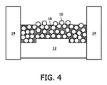
図4は、本発明の第2実施形態による光放出デバイスを作製する、作製第二段階の形成デバイスの横断面図である。 FIG. 4 is a cross-sectional view of a forming device in a second stage of manufacturing a light-emitting device according to the second embodiment of the present invention.
図5は、本発明の第2実施形態による光放出デバイスを作製する、作製第三段階の形成デバイスの横断面図である。 FIG. 5 is a cross-sectional view of a forming device in a third stage of manufacturing a light-emitting device according to the second embodiment of the present invention.
図6は、図3乃至図5の形成デバイスで作製されたマトリックス材料中に組み込まれた本発明の第2実施形態によるセラミック球状色変換材料の集合図である。 FIG. 6 is an aggregate view of a ceramic spherical color conversion material according to a second embodiment of the present invention incorporated into a matrix material made with the forming device of FIGS. 3-5.
図7は、本発明の第3の実施形態による光放出デバイスを作製する、作製第一段階の形成デバイスの横断面図である。 FIG. 7 is a cross-sectional view of a forming device in the first stage of manufacturing a light-emitting device according to the third embodiment of the present invention.
図8は、第3および第4の実施形態によるセラミック球状色変換材料の二つの更なる組み立て図である。 FIG. 8 is two further assembly views of ceramic spherical color conversion materials according to the third and fourth embodiments.
図9は、二種類のセラミック球状色変換材料を有する本発明の第5の実施形態による光放出デバイスの概略配置を示す図である。 FIG. 9 is a diagram showing a schematic arrangement of a light emitting device according to a fifth embodiment of the present invention having two types of ceramic spherical color conversion materials.
図10は、本発明の第6の実施形態による光放出デバイスの概略配置を示す図である。 FIG. 10 is a diagram showing a schematic arrangement of a light emitting device according to the sixth embodiment of the present invention.
図1は、本発明の第1実施形態によるセラミック球状色変換材料10の第1の集合30の部分概略斜視図である。セラミック球状色変換材料10は多くの用途で層類似構造の形で容易に供給できることが分かる。
FIG. 1 is a partial schematic perspective view of a
図2は本発明の第1実施形態によるセラミック球状色変換材料を集合させるための準備の部分概略斜視図である。この準備には単純に傾斜板60が含まれ、傾斜板と水平軸との間の角度が適切に設定された場合には、セラミック球状色変換材料10は、容易に所望の集合が形成されるであろう。本発明の利点は、セラミック球状色変換材料および/またはこのようなセラミック球状色変換材料を用いる光放出デバイスの製造の多くのステップにとって、ここで用いられる技法は、広範な用途で高度な設備を必要することなく、とても容易に準備できるだろうということである。
FIG. 2 is a partial schematic perspective view of the preparation for assembling the ceramic spherical color conversion material according to the first embodiment of the present invention. In this preparation, the
図3は、本発明の第2実施形態による光放出デバイスを作製する、作製第一段階の形成デバイスの横断面図であり、図4および図5は第二および第三段階を示す図である。 FIG. 3 is a cross-sectional view of a forming device in a first stage of manufacturing a light-emitting device according to a second embodiment of the present invention, and FIGS. 4 and 5 are diagrams illustrating second and third stages. .
この形成デバイスは単純にいくつかのモールド12、14および18を有する。最初に、モールド12および14が供給され、セラミック球状色変換材料10が単純にモールドに充填される。セラミック球状色変換材料10の量は、好ましくは、光放出デバイスが製造される場合にはいくつかの層を築くように設定される。
This forming device simply has
第二段階では(図4に示すように)マトリックス材料16および/またはマトリックス前駆物質材料16が添加される。製造されるデバイス中でセラミック球状色変換材料10間の空間を埋めるであろうこのマトリックス材料は、好ましくは上記のような材料である。
In the second stage,
最後に、図5に示すように、さらなるモールド18が現在のモールド12および14に加えられ、セラミック球状色変換材料10およびマトリックス(前駆物質)材料は、セラミック球状色変換材料10が層構造を形成するように矢印A方向に加圧される。
Finally, as shown in FIG. 5, an
加圧中またはその後に、マトリックス前駆物質材料16はポリマーおよび/またはガラス類似構造を形成するように処理されてもよい。これは、例えば、マトリックス前駆物質材料16を加熱することによる融解で達成してもよい。
During or after pressurization, the
図6は、図3乃至図5の形成デバイスで作製されるマトリックス材料中に組み込まれる本発明の第2実施形態によるセラミック球状色変換材料の集合(30’)の図である。さらなるステップにおいて、光源40(図示しないが図6において示されている)が加えられる。この光源は当該技術分野における当業者に知られているどのような光源、例えば、AlInGaN LEDダイを含んでいてもよい。 FIG. 6 is an illustration of a collection (30 ') of ceramic spherical color conversion materials according to a second embodiment of the present invention incorporated into a matrix material made with the forming device of FIGS. In a further step, a light source 40 (not shown but shown in FIG. 6) is added. The light source may include any light source known to those skilled in the art, such as an AlInGaN LED die.
セラミック球状色変換材料の球の直径およびモールド空間の外形寸法を適切に選択すれば、次式の最大球実装密度Dが色変換配置30’において達成され得る。 With appropriate selection of the sphere diameter of the ceramic spherical color conversion material and the outer dimensions of the mold space, a maximum sphere mounting density D of the following equation can be achieved in the color conversion arrangement 30 '.
D=π/(3√2)=0.7405 D = π / (3√2) = 0.7405
図7は、本発明の第3の実施形態による光放出デバイスを作製する、作製第一段階の形成デバイスの横断面図である。この形成デバイスの組み立ては、最初からすでに光源40が供給されている点を除いて、図3乃至図5と類似しているが、モールド12’は異なって形状をしている。
FIG. 7 is a cross-sectional view of a forming device in the first stage of manufacturing a light-emitting device according to the third embodiment of the present invention. The assembly of the forming device is similar to FIGS. 3-5 except that the
図8は、本発明の第3および第4の実施形態によるセラミック球状色変換材料10の二つの更なる集合図32および34である。適切に形成されていれば、セラミック球状色変換材料10は自分自身で層類似構造32、34に配置することが分かる。セラミック球状色変換材料10の配置の長さd1およびd2は容易に計算することができる。
FIG. 8 is two further
長さd1およびd2はセラミック球状色変換材料によって変換される光量に影響するであろうことは言うまでもない。光放出デバイスの配置および/または製造が容易に達成でき、本発明範囲内の広範な用途でセラミック球状色変換材料配置の長さをとても信頼して計算できるので、セラミック球状色変換材料は光放出デバイスの演色特性および/または相関色温度(CCT)の設定および/または調整には信頼性がある。セラミック球状色変換材料の球をさらに追加することで、CCTをシフトさせてもよい。 Of course, the lengths d1 and d2 will affect the amount of light converted by the ceramic spherical color conversion material. Ceramic spherical color conversion materials are light emitting because the arrangement and / or manufacture of light emitting devices can be easily achieved and the length of the ceramic spherical color conversion material arrangement can be calculated very reliably for a wide range of applications within the scope of the present invention. The setting and / or adjustment of the color rendering properties and / or correlated color temperature (CCT) of the device is reliable. The CCT may be shifted by adding more spheres of ceramic spherical color conversion material.
変換される二次光の量は、色変換組み立ての厚さでとても正確に制御可能である。この厚さは、球を最蜜に配置した組み立ての場合には下記の値になってもよい。 The amount of secondary light converted can be controlled very accurately by the thickness of the color conversion assembly. This thickness may be the following value in the case of an assembly in which the spheres are arranged at the most dense position.
dn=2√3rn d n = 2√3 rn
ここで、dnは集合させられた球の層の厚さであり、rは球の半径であり、nは六角形に実装された球層の数である。実際この値は、本質的に、本発明範囲内の多くの用途で、ほんのわずかな偏差しか発生しなかった。 Here, d n is the thickness of the layer of the sphere was allowed to set, r is the radius of the sphere, n is the number of spheres layer mounted on hexagonal. In fact, this value essentially resulted in only a small deviation for many applications within the scope of the present invention.
図9は、二種類のセラミック球状色変換材料を有する本発明の第5の実施形態による光放出デバイスの概略配置を示す図である。 FIG. 9 is a diagram showing a schematic arrangement of a light emitting device according to a fifth embodiment of the present invention having two types of ceramic spherical color conversion materials.
この実施形態では、二つのセラミック球状色変換材料10および20の二つの集合36、38があり、それらはお互いに接して層類似構造で供給される。光放出デバイスは、さらにセラミック球状色変換材料で二次光40bに変換される一次光40aを放出する光源40(AlInGaN LEDダイ等)を有する。二次光40bは、セラミック球状色変換材料の特性に依存する一定量の一次光40aをも有してもよい。二つのセラミック球状色変換材料は材料が異なり、放出特性も異なるであろうから、LEDの発光特性を変化させることが可能となる。
In this embodiment, there are two
図9(または、さらにもっと異なるセラミック球状色変換材料が存在する他の実施形態−図示せず−)による光放出デバイスを提供する場合にも光放出デバイスの演色特性および/または相関色温度(CCT)の調整および/または設定が可能であることは言うまでもない。 The color rendering properties and / or correlated color temperature (CCT) of the light emitting device may also be provided when providing a light emitting device according to FIG. 9 (or other embodiments in which there are even different ceramic spherical color conversion materials—not shown). Needless to say, adjustment and / or setting of () is possible.
また、さらに別の実施形態(図示せず)によれば、さらに別の色変換材料をマトリックス材料16に(図3に示すように)組み込む。製造される光放出デバイスでは、さらに別の層を使用する必要なく、やはり二種類の色変換材料が存在するであろう。これは、本発明の範囲内のいくつかの用途にとって有利であることを示している。 Also, according to yet another embodiment (not shown), yet another color conversion material is incorporated into the matrix material 16 (as shown in FIG. 3). In a manufactured light emitting device, there will still be two types of color conversion materials without the need to use additional layers. This shows an advantage for some applications within the scope of the present invention.
二つの球状材料が存在するさらに別の実施形態(図示しないが、図9と類似している)では、ひとつは色変換をし、他のもう一つは色変換をしない。この場合にも、光放出デバイスの相関色温度(CCT)の調整および/または設定が可能である。非色変換材料は、ある意味で色変換材料に対する“希釈(diluting)”材料の役目をする。このような構造によれば、多くの用途で色変換球と非色変換球との比さえ変化させれば、異なるCCT(あるいは他の光学特徴)を有する同じ大きさの光放出デバイスに容易に到達できる。 In yet another embodiment where two spherical materials are present (not shown but similar to FIG. 9), one performs color conversion and the other does not. In this case as well, the correlation color temperature (CCT) of the light emitting device can be adjusted and / or set. The non-color converting material serves in a sense as a “diluting” material for the color converting material. With such a structure, it is easy to produce a light emitting device of the same size with different CCTs (or other optical features) as long as the ratio of the color conversion sphere to the non-color conversion sphere is changed in many applications. Can reach.
図10は、本発明の第6の実施形態による光源40を有する光放出デバイスの概略配置を示す図である。この実施形態では、セラミック球状色変換材料は、光を反射できる“ガラスドーム”50として設置される。光源40はセラミック球状色変換材料の方向に光を放出する。このような構造によれば、セラミック球状色変換材料の変換効率はさらに向上させることができる。
FIG. 10 is a diagram showing a schematic arrangement of a light emitting device having a
本発明は、本発明のさらに別の実施形態によるセラミック球状色変換材料の製造方法を示す次の実施例I(単に説明だけである)によってさらに理解されよう。 The invention will be further understood by the following Example I (which is merely illustrative) showing a method of making a ceramic spherical color conversion material according to yet another embodiment of the invention.
実施例I
Al2O3(99.99%、平均粒径350nm)、Y2O3(99.99%、平均粒径700nm)およびCeO2(>98.5%、平均粒径40nm)を、イソプロパノール中で高純度アルミナのミリング媒体(ニッカト−製、SSA−W999)で粉砕した。ポリビニルブチラールバインダー(積水製、BM−S)を添加後に、粉末懸濁液を乾燥させ、顆粒直径が80〜120μmの範囲の顆粒を形成するように粒状化にした。そして顆粒を平均直径800μmのビーズに常温圧縮(cold pressed)し、空気中500℃でデバインドした(debindered)。
Example I
Al 2 O 3 (99.99%, average particle size 350 nm), Y 2 O 3 (99.99%, average particle size 700 nm) and CeO 2 (> 98.5%,
そしてビーズを防水性のポリエチレンコーティング層で覆った。ポリエチレンコーティングでは200〜400℃の範囲の温度での流動層コーティングを適用したが、代わりに静電塗装またはフロックコーティングを使用してもよい。 The beads were then covered with a waterproof polyethylene coating layer. For the polyethylene coating, fluidized bed coating at a temperature in the range of 200-400 ° C. was applied, but electrostatic or flock coating may be used instead.
そしてコーティングされたビーズは2000〜4500バールの範囲の圧力で冷間等方圧加圧された。加圧後に、残留有機バインダーおよびコーティングは1000℃で12時間、空気中でビーズを焼成して除去された(加熱勾配(heating ramp),50K/h)。デバインドされたセラミック素地を1750℃の一酸化炭素雰囲気中で2時間かけて焼結した。 The coated beads were then cold isostatically pressed at a pressure in the range of 2000-4500 bar. After pressing, the residual organic binder and coating were removed by baking the beads in air for 12 hours at 1000 ° C. (heating ramp, 50 K / h). The debound ceramic body was sintered in a carbon monoxide atmosphere at 1750 ° C. for 2 hours.
焼結および適度な研磨によるデアグロメレーション後、セラミックYAG:Ce球を1700℃、500バールアルゴン(4.8)で熱間等方圧加圧した。そして、最終的な表面仕上げおよび直径に到達するまで、市販されているミリングおよび研磨用添加剤を用いてローラベンチ上で湿式粉砕により、透明球を研削および/または研磨した。洗浄後、セラミック球を空気中1350℃で4時間かけて後焼きなまし(postannealed)をした。 After deagglomeration by sintering and moderate polishing, a ceramic YAG: Ce sphere was hot isostatically pressed at 1700 ° C. and 500 bar argon (4.8). The transparent spheres were then ground and / or polished by wet grinding on a roller bench using commercially available milling and polishing additives until the final surface finish and diameter were reached. After washing, the ceramic spheres were post-annealed in air at 1350 ° C. for 4 hours.
この結果セラミック球状色変換材料は平均直径が450μmで、理想的な球状形状からの形状の平均偏差が1%未満となった。 As a result, the ceramic spherical color conversion material had an average diameter of 450 μm, and the average deviation of the shape from the ideal spherical shape was less than 1%.
前述された詳細な実施形態の要素および特徴の特定の組み合わせは一例にすぎず、これらの教示と、本明細書および参照として取り入れられた特許/特許出願の他の教示との交換および置換も明確に考慮される。当業者であれば、請求項に記載されている本発明の精神および範囲から逸脱することなく、本明細書に記述されたものの変形、修正、および他の実施形態を想到可能であることを当業者は理解するであろう。従って、前述の記載は実施例にすぎず、限定して解釈すべきではない。本発明の範囲は、特許請求の範囲およびそれらと均等の範囲によって定義される。さらに、明細書および請求項に使用されている参照記号は請求項に記載される本発明の範囲を限定するものではない。 The specific combinations of elements and features of the detailed embodiments described above are merely examples, and the exchange and substitution of these teachings with other teachings of this specification and patents / patent applications incorporated by reference are clear. To be considered. Those skilled in the art will recognize that variations, modifications, and other embodiments of what is described herein may be made without departing from the spirit and scope of the invention as set forth in the claims. The merchant will understand. Accordingly, the foregoing description is by way of example only and should not be construed as limiting. The scope of the present invention is defined by the appended claims and their equivalents. Furthermore, reference signs used in the description and claims do not limit the scope of the invention described in the claims.
Claims (11)
少なくとも一つの光源および平均直径が100μm以上2500μm以下である少なくとも一つのセラミック球状色変換材料を有し、
前記少なくとも一つのセラミック球状色変換材料の密度は、対応する単結晶の理論密度の95%以上100%以下であり、
前記少なくとも一つのセラミック球状色変換材料は、
(a) 少なくとも一つのセラミック球状色変換材料の材料をプリフォームするステップと、
(b) プリフォームされた少なくとも一つのセラミック球状色変換材料の材料を加圧するステップと、
(c) 前記ステップ(b)において成形された少なくとも一つのセラミック球状色変換材料の任意の二次的な処理ステップと、を含む方法によって得られるものであり、
前記ステップ(b)は、少なくとも一つのセラミック球状色変換材料の静水圧圧縮成形処理を含む、
光放出デバイス。 A light emitting device comprising:
Have at least one ceramic spherical color converter material of at least one light source and the average diameter is 100μm or more 2500μm or less,
The density of the at least one ceramic spherical color conversion material is 95% or more and 100% or less of the theoretical density of the corresponding single crystal;
The at least one ceramic spherical color conversion material is:
(A) preforming at least one ceramic spherical color conversion material;
(B) pressing the preformed material of at least one ceramic spherical color conversion material;
And (c) an optional secondary processing step of at least one ceramic spherical color conversion material formed in step (b).
Step (b) includes a hydrostatic compression molding process of at least one ceramic spherical color conversion material,
Light emitting device.
(Lu1-x-y-a-bYxGdy)3(Al1-z-cGazSic)5O12-cNc:CeaPrb(0≦x≦1、0≦y≦1、0≦z≦0.1、0<a≦0.2、0<b≦0.1および0<c<1)、
(Sr1-x-yBaxCay)2-zSi5-aAlaN8-aOa:Euz 2+(0≦a≦5、0<x≦1、0≦Y≦1および0<z≦0.1)、
(Sr1-a-bCabBac)SixNyOz:Eua 2+(0.002≦a≦0.2、0.0≦b≦0.25、0.0≦c≦0.25、1.5≦x≦2.5、1.5≦y≦2.5、1.5≦z≦2.5)、
(Sr1-u-v-xCavBax)2(SiO4):Euu(0≦x≦1、0≦u≦0.1、0≦v≦1)、
(Ca1-x-ySrx)S:Eu2+ y(0≦x≦1、0≦y≦0.01)、
(Ca1-x-y-zSrxBayMgz)1-n(Al1-a+bBa)Si1-bN3-bOb:REn(0≦x≦1、0≦y≦1、0≦z≦1、0≦a≦1、0<b≦1および0.002≦n≦0.2およびREはEuおよび/またはCeから選択される。)、
Mx v+Si12-(m+n)Alm+nOnN16-n(x=m/v、Mは金属であり、好ましくはLi、Mg、Ca、Y、Sc、Ce、Pr、Nf、Sm、Eu、Gd、Tb、Dy、Ho、Er、Tm、Yb、Luまたはそれらの混合物を含むグループから選択される。)あるいは、
それらの混合物である光放出デバイス。 5. The light emitting device according to any of claims 1 to 4 , wherein the at least one ceramic spherical color conversion material is essentially manufactured from a material selected from the group:
(Lu 1-xyab Y x Gd y) 3 (Al 1-zc Ga z Si c) 5 O 12-c N c: Ce a Pr b (0 ≦ x ≦ 1,0 ≦ y ≦ 1,0 ≦ z ≦ 0.1, 0 <a ≦ 0.2, 0 <b ≦ 0.1 and 0 <c <1),
(Sr 1-xy Ba x Ca y) 2-z Si 5-a Al a N 8-a O a: Eu z 2+ (0 ≦ a ≦ 5,0 <x ≦ 1,0 ≦ Y ≦ 1 and 0 <Z ≦ 0.1),
(Sr 1-ab Ca b B c ) Si x N y O z : Eu a 2+ (0.002 ≦ a ≦ 0.2, 0.0 ≦ b ≦ 0.25, 0.0 ≦ c ≦ 0. 25, 1.5 ≦ x ≦ 2.5, 1.5 ≦ y ≦ 2.5, 1.5 ≦ z ≦ 2.5),
(Sr 1-uvx Ca v Ba x) 2 (SiO 4): Eu u (0 ≦ x ≦ 1,0 ≦ u ≦ 0.1,0 ≦ v ≦ 1),
(Ca 1-xy Sr x ) S: Eu 2+ y (0 ≦ x ≦ 1, 0 ≦ y ≦ 0.01),
(Ca 1-xyz Sr x Ba y Mg z) 1-n (Al 1-a + b B a) Si 1-b N 3-b O b: RE n (0 ≦ x ≦ 1,0 ≦ y ≦ 1 , 0 ≦ z ≦ 1, 0 ≦ a ≦ 1, 0 <b ≦ 1, and 0.002 ≦ n ≦ 0.2 and RE are selected from Eu and / or Ce).
M x v + Si 12- (m + n) Al m + n O n N 16-n (x = m / v, M is a metal, preferably Li, Mg, Ca, Y, Sc, Ce, Pr, Selected from the group comprising Nf, Sm, Eu, Gd, Tb, Dy, Ho, Er, Tm, Yb, Lu or mixtures thereof) or
A light emitting device that is a mixture of them.
(a) 少なくとも一つのセラミック球状色変換材料の材料をプリフォームするステップと、
(b) プリフォームされた少なくとも一つのセラミック球状色変換材料の材料を加圧するステップと、
(c) 前記ステップ(b)において成形された少なくとも一つのセラミック球状色変換材料の任意の二次的な処理ステップと、を含み
前記ステップ(b)が少なくとも一つのセラミック球状色変換材料の静水圧圧縮成形処理を含む、
方法。 At least one ceramic spherical color conversion having an average diameter of 100 μm or more and 2500 μm or less and a density of 95% or more and 100% or less of the theoretical density of the corresponding single crystal, which is used for a light emitting device having at least one light source A material supply method comprising:
(A) a step of preform material of at least one ceramic spherical color converter material,
(B) a step of the material of at least one ceramic spherical color converter material is preformed pressurized,
(C) viewing contains a and any secondary processing steps of said at least one ceramic spherical color converter material is molded in step (b)
The step (b) includes isostatic pressing of at least one ceramic spherical color conversion material;
Method.
事務照明システム、
家庭用途システム、
店舗照明システム、
家庭照明システム、
アクセント照明システム、
スポット照明システム、
劇場照明システム、
光ファイバー用途のシステム、
投影システム、
自己点灯(self−lit)ディスプレイシステム、
ピクセルで構成された(pixelated)ディスプレイシステム、
セグメント化された(segmented)ディスプレイシステム、
警標システム、
医療照明用システム、
指標(indicator sign)システム
装飾照明システム、
携帯システム、
自動車用途、および
温室照明システム。 In a system comprising a light emitting device according to any of claims 1 to 6 and / or at least one ceramic spherical color conversion material produced by the method of claim 7 or 8 , used in one or more of the following applications: Said system:
Office lighting system,
Home use system,
Store lighting system,
Home lighting system,
Accent lighting system,
Spot lighting system,
Theater lighting system,
Systems for optical fiber applications,
Projection system,
Self-lit display system,
A pixelated display system,
A segmented display system,
Warning sign system,
Medical lighting system,
Indicator system decorative lighting system,
Mobile system,
Automotive applications and greenhouse lighting systems.
Applications Claiming Priority (3)
| Application Number | Priority Date | Filing Date | Title |
|---|---|---|---|
| EP06115815.0 | 2006-06-21 | ||
| EP06115815 | 2006-06-21 | ||
| PCT/IB2007/052193 WO2007148253A1 (en) | 2006-06-21 | 2007-06-11 | Light emitting device with a at least one ceramic spherical color converter material |
Publications (3)
| Publication Number | Publication Date |
|---|---|
| JP2009541520A JP2009541520A (en) | 2009-11-26 |
| JP2009541520A5 JP2009541520A5 (en) | 2010-07-29 |
| JP5587601B2 true JP5587601B2 (en) | 2014-09-10 |
Family
ID=38543654
Family Applications (1)
| Application Number | Title | Priority Date | Filing Date |
|---|---|---|---|
| JP2009516014A Active JP5587601B2 (en) | 2006-06-21 | 2007-06-11 | Light emitting device having at least one ceramic spherical color conversion material |
Country Status (10)
| Country | Link |
|---|---|
| US (1) | US8120247B2 (en) |
| EP (1) | EP2036134B1 (en) |
| JP (1) | JP5587601B2 (en) |
| KR (1) | KR101421412B1 (en) |
| CN (2) | CN104882527B (en) |
| AT (1) | ATE470243T1 (en) |
| DE (1) | DE602007006952D1 (en) |
| RU (1) | RU2431219C2 (en) |
| TW (1) | TWI511321B (en) |
| WO (1) | WO2007148253A1 (en) |
Families Citing this family (18)
| Publication number | Priority date | Publication date | Assignee | Title |
|---|---|---|---|---|
| JP2008285606A (en) * | 2007-05-18 | 2008-11-27 | Nec Lighting Ltd | Phosphor, method for manufacturing the same, and light emitting device |
| US8482191B2 (en) | 2008-08-11 | 2013-07-09 | Osram Gesellschaft Mit Beschraenkter Haftung | Conversion LED |
| DE102008045331A1 (en) | 2008-09-01 | 2010-03-04 | Osram Opto Semiconductors Gmbh | Optoelectronic component |
| JP5682104B2 (en) * | 2008-09-05 | 2015-03-11 | 三菱化学株式会社 | Phosphor and method for producing the same, phosphor-containing composition and light emitting device using the phosphor, and image display device and lighting device using the light emitting device |
| DE102008057140A1 (en) | 2008-11-13 | 2010-05-20 | Osram Opto Semiconductors Gmbh | Optoelectronic component |
| EP2412038B1 (en) * | 2009-03-19 | 2019-01-02 | Philips Lighting Holding B.V. | Illumination device with remote luminescent material |
| DE102011113962B4 (en) * | 2011-09-21 | 2024-02-08 | OSRAM Opto Semiconductors Gesellschaft mit beschränkter Haftung | Method for producing a ceramic conversion element |
| JP6002772B2 (en) * | 2011-10-17 | 2016-10-05 | グリレム アドヴァンスド マテリアルズ カンパニー リミテッドGrirem Advanced Materials Co.,Ltd. | Nitride red light emitting material, light emitting element and light emitting device including the same |
| CN102494305A (en) * | 2011-11-24 | 2012-06-13 | 上海大学 | Color-adjustable light source |
| CN102994079A (en) * | 2012-12-21 | 2013-03-27 | 北京有色金属研究总院 | Nitrogen-oxide orange-red fluorescent material comprising light-emitting film or light-emitting piece and light-emitting device |
| WO2014155227A1 (en) * | 2013-03-29 | 2014-10-02 | Koninklijke Philips N.V. | Light emitting device comprising wavelength converter |
| JP6273464B2 (en) * | 2013-06-21 | 2018-02-07 | パナソニックIpマネジメント株式会社 | Red phosphor material and light emitting device |
| JP6286676B2 (en) | 2013-06-21 | 2018-03-07 | パナソニックIpマネジメント株式会社 | Red phosphor material and light emitting device |
| JP2015142046A (en) * | 2014-01-29 | 2015-08-03 | シャープ株式会社 | Wavelength conversion member, light emitting device, and method of manufacturing wavelength conversion member |
| DE102014107473A1 (en) * | 2014-05-27 | 2015-12-03 | Osram Opto Semiconductors Gmbh | Converter element for converting a wavelength, optoelectronic component with converter element and method for producing a converter element |
| DE102015203578A1 (en) * | 2015-02-27 | 2016-09-01 | Fraunhofer-Gesellschaft zur Förderung der angewandten Forschung e.V. | PROCESS FOR PRODUCING OPTOELECTRONIC COMPONENTS AND OPTOELECTRONIC COMPONENTS |
| JPWO2017056470A1 (en) * | 2015-09-29 | 2018-07-19 | パナソニックIpマネジメント株式会社 | Wavelength conversion element and light emitting device |
| KR102585238B1 (en) | 2017-12-28 | 2023-10-06 | 삼성디스플레이 주식회사 | Organic light-emitting display device and method of manufacturing the same |
Family Cites Families (34)
| Publication number | Priority date | Publication date | Assignee | Title |
|---|---|---|---|---|
| JPH069956A (en) * | 1991-12-27 | 1994-01-18 | Fuji Photo Film Co Ltd | Spherical sintered phosphor and its production |
| JP2739061B2 (en) * | 1993-03-15 | 1998-04-08 | 日本電信電話株式会社 | Method for producing infrared stimulable phosphor, infrared stimulable phosphor, and infrared-visible conversion element using infrared stimulable phosphor |
| EP0918045A1 (en) | 1997-02-18 | 1999-05-26 | Mikuni Corporation | Ceramic granules |
| US7625420B1 (en) * | 1997-02-24 | 2009-12-01 | Cabot Corporation | Copper powders methods for producing powders and devices fabricated from same |
| US6197218B1 (en) * | 1997-02-24 | 2001-03-06 | Superior Micropowders Llc | Photoluminescent phosphor powders, methods for making phosphor powders and devices incorporating same |
| EP1127098A4 (en) * | 1998-08-27 | 2006-05-24 | Superior Micropowders Llc | PHOSPHORUS POWDERS, METHODS OF MAKING PHOSPHORUS POWDERS, AND DEVICES INCLUDING THE SAME |
| US6429583B1 (en) * | 1998-11-30 | 2002-08-06 | General Electric Company | Light emitting device with ba2mgsi2o7:eu2+, ba2sio4:eu2+, or (srxcay ba1-x-y)(a1zga1-z)2sr:eu2+phosphors |
| US6246744B1 (en) * | 1999-05-06 | 2001-06-12 | General Electric Company | Cubic garnet host with PR activator as a scintillator material |
| KR20020070337A (en) * | 2000-11-22 | 2002-09-05 | 도쿠슈 페이퍼 매뉴팩츄어링 가부시키가이샤 | Particles emitting fluorescence by irradiation of infrared ray and forgery preventing paper using the same |
| JP3749243B2 (en) * | 2001-09-03 | 2006-02-22 | 松下電器産業株式会社 | Semiconductor light emitting device, light emitting apparatus, and method for manufacturing semiconductor light emitting device |
| US6734466B2 (en) * | 2002-03-05 | 2004-05-11 | Agilent Technologies, Inc. | Coated phosphor filler and a method of forming the coated phosphor filler |
| ATE521092T1 (en) * | 2002-04-25 | 2011-09-15 | Nichia Corp | LIGHT-EMITTING COMPONENT WITH A FLUORESCENT SUBSTANCE |
| AUPS327002A0 (en) * | 2002-06-28 | 2002-07-18 | Kabay & Company Pty Ltd | An electroluminescent light emitting device |
| US7768189B2 (en) * | 2004-08-02 | 2010-08-03 | Lumination Llc | White LEDs with tunable CRI |
| US7554258B2 (en) * | 2002-10-22 | 2009-06-30 | Osram Opto Semiconductors Gmbh | Light source having an LED and a luminescence conversion body and method for producing the luminescence conversion body |
| RU2219622C1 (en) * | 2002-10-25 | 2003-12-20 | Закрытое акционерное общество "Светлана-Оптоэлектроника" | Semiconductor white light source |
| JP3717480B2 (en) * | 2003-01-27 | 2005-11-16 | ローム株式会社 | Semiconductor light emitting device |
| JP2004235546A (en) * | 2003-01-31 | 2004-08-19 | Mitsubishi Chemicals Corp | Light emitting device, lighting device and display using the same |
| JP2004265866A (en) * | 2003-02-14 | 2004-09-24 | Fuji Photo Film Co Ltd | Electroluminescence element |
| JP2005041942A (en) * | 2003-07-24 | 2005-02-17 | Mitsubishi Chemicals Corp | Luminescent substance, light emitting device using the same, lighting device using light emitting device, and image display device |
| US7238304B2 (en) * | 2003-08-04 | 2007-07-03 | Kabushiki Kaisha Fine Rubber Kenkyuusho | Green light emitting phosphor and light emitting device |
| JP2005294185A (en) * | 2004-04-05 | 2005-10-20 | Nichia Chem Ind Ltd | Light emitting device |
| US20050122034A1 (en) * | 2003-12-08 | 2005-06-09 | Fuji Photo Film Co., Ltd. | Electroluminescent device |
| JP2005197234A (en) * | 2003-12-08 | 2005-07-21 | Fuji Photo Film Co Ltd | Electroluminescence element |
| KR100610249B1 (en) * | 2003-12-23 | 2006-08-09 | 럭스피아 주식회사 | Yellow light emitting phosphor and white semiconductor light emitting device using the same |
| JP2005277331A (en) * | 2004-03-26 | 2005-10-06 | Kyocera Corp | Light emitting device and lighting device |
| US20050211991A1 (en) * | 2004-03-26 | 2005-09-29 | Kyocera Corporation | Light-emitting apparatus and illuminating apparatus |
| US20070262702A1 (en) * | 2004-03-31 | 2007-11-15 | Shunsuke Fujita | Phoshor and Light-Emitting Diode |
| US7488990B2 (en) | 2004-04-02 | 2009-02-10 | Avago Technologies Ecbu Ip (Singapore) Pte. Ltd. | Using multiple types of phosphor in combination with a light emitting device |
| JP4583076B2 (en) * | 2004-06-11 | 2010-11-17 | スタンレー電気株式会社 | Light emitting element |
| JP3802911B2 (en) * | 2004-09-13 | 2006-08-02 | ローム株式会社 | Semiconductor light emitting device |
| US7265488B2 (en) * | 2004-09-30 | 2007-09-04 | Avago Technologies General Ip Pte. Ltd | Light source with wavelength converting material |
| DE602005010122D1 (en) * | 2005-01-04 | 2008-11-13 | Philips Intellectual Property | WAVELENGTH CONVERSION LAYERS WITH EMBEDDED CRYSTALLITES |
| JP4788944B2 (en) * | 2005-03-18 | 2011-10-05 | 株式会社フジクラ | Powdered phosphor, method for manufacturing the same, light emitting device, and lighting apparatus |
-
2007
- 2007-06-11 KR KR1020097001145A patent/KR101421412B1/en active Active
- 2007-06-11 WO PCT/IB2007/052193 patent/WO2007148253A1/en not_active Ceased
- 2007-06-11 DE DE602007006952T patent/DE602007006952D1/en active Active
- 2007-06-11 RU RU2009101791/28A patent/RU2431219C2/en active
- 2007-06-11 EP EP07766702A patent/EP2036134B1/en active Active
- 2007-06-11 US US12/305,380 patent/US8120247B2/en active Active
- 2007-06-11 AT AT07766702T patent/ATE470243T1/en not_active IP Right Cessation
- 2007-06-11 JP JP2009516014A patent/JP5587601B2/en active Active
- 2007-06-11 CN CN201510360498.7A patent/CN104882527B/en active Active
- 2007-06-11 CN CNA2007800233226A patent/CN101473459A/en active Pending
- 2007-06-15 TW TW096121934A patent/TWI511321B/en active
Also Published As
| Publication number | Publication date |
|---|---|
| US20090174309A1 (en) | 2009-07-09 |
| CN101473459A (en) | 2009-07-01 |
| EP2036134A1 (en) | 2009-03-18 |
| JP2009541520A (en) | 2009-11-26 |
| WO2007148253A1 (en) | 2007-12-27 |
| RU2009101791A (en) | 2010-07-27 |
| CN104882527B (en) | 2018-05-15 |
| KR101421412B1 (en) | 2014-07-22 |
| RU2431219C2 (en) | 2011-10-10 |
| TW200808114A (en) | 2008-02-01 |
| KR20090037432A (en) | 2009-04-15 |
| CN104882527A (en) | 2015-09-02 |
| ATE470243T1 (en) | 2010-06-15 |
| TWI511321B (en) | 2015-12-01 |
| DE602007006952D1 (en) | 2010-07-15 |
| US8120247B2 (en) | 2012-02-21 |
| EP2036134B1 (en) | 2010-06-02 |
Similar Documents
| Publication | Publication Date | Title |
|---|---|---|
| JP5587601B2 (en) | Light emitting device having at least one ceramic spherical color conversion material | |
| CN101605866B (en) | Lighting systems incorporating composite monolithic ceramic luminescence converters | |
| CN101305072B (en) | There is the luminescent device of the CaAlSiN light-converting material of improvement | |
| US8169136B2 (en) | Light emitting device with translucent ceramic plate | |
| US9966512B2 (en) | Light scattering and conversion plate for LEDs | |
| JP2009541520A5 (en) | ||
| KR102059425B1 (en) | Oxide Ceramic Fluorescent Material Having Rare Earth Diffused Therein | |
| US8721925B2 (en) | Co-doped silicooxynitrides | |
| JP6941821B2 (en) | Wavelength converter, its manufacturing method, and light emitting device using the wavelength converter | |
| KR20090089384A (en) | Lighting system comprising monolithic ceramic light-emitting converter, composite monolithic ceramic light-emitting converter and method for manufacturing composite monolithic ceramic light-emitting converter | |
| CN112441817A (en) | Fluorescent ceramic, preparation method thereof and light source device | |
| KR20080056258A (en) | Light-Emitting Element Having Ceramic SiAONON Material | |
| JP2012532079A (en) | Green light emitting material |
Legal Events
| Date | Code | Title | Description |
|---|---|---|---|
| A521 | Request for written amendment filed |
Free format text: JAPANESE INTERMEDIATE CODE: A523 Effective date: 20100609 |
|
| A621 | Written request for application examination |
Free format text: JAPANESE INTERMEDIATE CODE: A621 Effective date: 20100609 |
|
| A131 | Notification of reasons for refusal |
Free format text: JAPANESE INTERMEDIATE CODE: A131 Effective date: 20121105 |
|
| A521 | Request for written amendment filed |
Free format text: JAPANESE INTERMEDIATE CODE: A523 Effective date: 20130205 |
|
| RD02 | Notification of acceptance of power of attorney |
Free format text: JAPANESE INTERMEDIATE CODE: A7422 Effective date: 20130912 |
|
| A02 | Decision of refusal |
Free format text: JAPANESE INTERMEDIATE CODE: A02 Effective date: 20131202 |
|
| RD04 | Notification of resignation of power of attorney |
Free format text: JAPANESE INTERMEDIATE CODE: A7424 Effective date: 20140122 |
|
| A521 | Request for written amendment filed |
Free format text: JAPANESE INTERMEDIATE CODE: A523 Effective date: 20140402 |
|
| A911 | Transfer to examiner for re-examination before appeal (zenchi) |
Free format text: JAPANESE INTERMEDIATE CODE: A911 Effective date: 20140410 |
|
| TRDD | Decision of grant or rejection written | ||
| A01 | Written decision to grant a patent or to grant a registration (utility model) |
Free format text: JAPANESE INTERMEDIATE CODE: A01 Effective date: 20140701 |
|
| A61 | First payment of annual fees (during grant procedure) |
Free format text: JAPANESE INTERMEDIATE CODE: A61 Effective date: 20140724 |
|
| R150 | Certificate of patent or registration of utility model |
Ref document number: 5587601 Country of ref document: JP Free format text: JAPANESE INTERMEDIATE CODE: R150 |
|
| R250 | Receipt of annual fees |
Free format text: JAPANESE INTERMEDIATE CODE: R250 |
|
| R250 | Receipt of annual fees |
Free format text: JAPANESE INTERMEDIATE CODE: R250 |
|
| S111 | Request for change of ownership or part of ownership |
Free format text: JAPANESE INTERMEDIATE CODE: R313113 |
|
| R350 | Written notification of registration of transfer |
Free format text: JAPANESE INTERMEDIATE CODE: R350 |
|
| R250 | Receipt of annual fees |
Free format text: JAPANESE INTERMEDIATE CODE: R250 |
|
| R250 | Receipt of annual fees |
Free format text: JAPANESE INTERMEDIATE CODE: R250 |
|
| R250 | Receipt of annual fees |
Free format text: JAPANESE INTERMEDIATE CODE: R250 |
|
| R250 | Receipt of annual fees |
Free format text: JAPANESE INTERMEDIATE CODE: R250 |
|
| R250 | Receipt of annual fees |
Free format text: JAPANESE INTERMEDIATE CODE: R250 |
|
| R250 | Receipt of annual fees |
Free format text: JAPANESE INTERMEDIATE CODE: R250 |
|
| R250 | Receipt of annual fees |
Free format text: JAPANESE INTERMEDIATE CODE: R250 |