JP5589948B2 - Battery manufacturing method - Google Patents
Battery manufacturing method Download PDFInfo
- Publication number
- JP5589948B2 JP5589948B2 JP2011098160A JP2011098160A JP5589948B2 JP 5589948 B2 JP5589948 B2 JP 5589948B2 JP 2011098160 A JP2011098160 A JP 2011098160A JP 2011098160 A JP2011098160 A JP 2011098160A JP 5589948 B2 JP5589948 B2 JP 5589948B2
- Authority
- JP
- Japan
- Prior art keywords
- electrode
- battery
- positive electrode
- welding
- negative electrode
- Prior art date
- Legal status (The legal status is an assumption and is not a legal conclusion. Google has not performed a legal analysis and makes no representation as to the accuracy of the status listed.)
- Expired - Fee Related
Links
Images




Classifications
-
- Y—GENERAL TAGGING OF NEW TECHNOLOGICAL DEVELOPMENTS; GENERAL TAGGING OF CROSS-SECTIONAL TECHNOLOGIES SPANNING OVER SEVERAL SECTIONS OF THE IPC; TECHNICAL SUBJECTS COVERED BY FORMER USPC CROSS-REFERENCE ART COLLECTIONS [XRACs] AND DIGESTS
- Y02—TECHNOLOGIES OR APPLICATIONS FOR MITIGATION OR ADAPTATION AGAINST CLIMATE CHANGE
- Y02E—REDUCTION OF GREENHOUSE GAS [GHG] EMISSIONS, RELATED TO ENERGY GENERATION, TRANSMISSION OR DISTRIBUTION
- Y02E60/00—Enabling technologies; Technologies with a potential or indirect contribution to GHG emissions mitigation
- Y02E60/10—Energy storage using batteries
-
- Y—GENERAL TAGGING OF NEW TECHNOLOGICAL DEVELOPMENTS; GENERAL TAGGING OF CROSS-SECTIONAL TECHNOLOGIES SPANNING OVER SEVERAL SECTIONS OF THE IPC; TECHNICAL SUBJECTS COVERED BY FORMER USPC CROSS-REFERENCE ART COLLECTIONS [XRACs] AND DIGESTS
- Y02—TECHNOLOGIES OR APPLICATIONS FOR MITIGATION OR ADAPTATION AGAINST CLIMATE CHANGE
- Y02P—CLIMATE CHANGE MITIGATION TECHNOLOGIES IN THE PRODUCTION OR PROCESSING OF GOODS
- Y02P70/00—Climate change mitigation technologies in the production process for final industrial or consumer products
- Y02P70/50—Manufacturing or production processes characterised by the final manufactured product
Landscapes
- Secondary Cells (AREA)
- Connection Of Batteries Or Terminals (AREA)
Description
本発明は,電池の製造方法に関する。さらに詳細には,電極体の電極集電部を電極端子に溶接する際における,電極集電部に加わる応力の緩和を図った電池の製造方法に関するものである。 The present invention relates to a process for the production of batteries. More particularly, definitive in welding the electrode current collector of the electrode body to the electrode terminals, a method of manufacturing a mitigating efforts were batteries of stress applied to the electrode current collector.
電池は,携帯電話やパーソナルコンピュータ等の電子機器,ハイブリッド車両や電気自動車等の車両など,多岐にわたる分野で利用されている。これらのうち,車両や大型電子機器類には,単電池を直列または並列につないだ組電池が搭載されることが一般的である。 Batteries are used in various fields such as electronic devices such as mobile phones and personal computers, vehicles such as hybrid vehicles and electric vehicles. Of these, assembled batteries in which single cells are connected in series or in parallel are generally mounted on vehicles and large electronic devices.
このような電池のうちには,集電部の突出している電極体を有する電池がある。このような電極体では,電極体の一方の側に正極集電部の突出している正極突出部と,他方の側に負極集電部の突出している負極突出部とが設けられている。そして,正極突出部および負極突出部(以下,「電極突出部」という)はそれぞれ,正極端子および負極端子(以下,「電極端子」という)に溶接されている。 Among such batteries, there is a battery having an electrode body with a protruding current collector. In such an electrode body, a positive electrode protruding portion protruding from the positive electrode current collector is provided on one side of the electrode body, and a negative electrode protruding portion protruding from the negative electrode current collector on the other side. The positive electrode protruding portion and the negative electrode protruding portion (hereinafter referred to as “electrode protruding portion”) are welded to the positive electrode terminal and the negative electrode terminal (hereinafter referred to as “electrode terminal”), respectively.
そして,この溶接は好適になされることが好ましい。電極体からの集電を確実に行うためである。そのため,例えば特許文献1には,電極突出部と電極端子との溶接箇所以外に,電極突出部同士を溶融接着した溶融接着部を形成する技術が開示されている(特許文献1の段落[0040]―[0042]参照)。これにより,電極突出部と電極端子との抵抗値が小さいものとなるとしている(特許文献1の段落[0051]―[0054]参照)。 And it is preferable that this welding is made suitably. This is for reliably collecting current from the electrode body. Therefore, for example, Patent Document 1 discloses a technique for forming a melt-bonded portion in which electrode protruding portions are melt-bonded to each other in addition to the welded portion between the electrode protruding portion and the electrode terminal (see paragraph [0040] of Patent Document 1). ]-[0042]). As a result, the resistance value between the electrode protrusion and the electrode terminal is reduced (see paragraphs [0051] to [0054] of Patent Document 1).
ところで,電極体の電極突出部を電極端子に複数の溶接箇所で溶接する場合,電極突出部に箔折れや箔潰れが生ずることがある。箔折れ等が生じている箇所の強度は弱い。そして,その箇所に応力が加わると,箔が切れてしまうことがある。箔切れが生じている箇所から集電をすることはできない。これでは,電池から必要な出力を得ることができない。 By the way, when the electrode protrusion part of the electrode body is welded to the electrode terminal at a plurality of welding locations, the electrode protrusion part may be folded or crushed. The strength of the portion where the foil is broken is weak. And if stress is applied to the location, the foil may break. It is not possible to collect current from the location where the foil is cut. This makes it impossible to obtain the necessary output from the battery.
本発明は,前述した従来の技術が有する問題点を解決するためになされたものである。すなわちその課題とするところは,電極体の電極突出部を電極端子に複数の溶接箇所で溶接する際における,電極突出部に加わる応力の緩和を図った電池の製造方法を提供することである。 The present invention has been made to solve the above-described problems of the prior art. That it is an object is definitive in welding at a plurality of welding points of the electrode projecting portions of the electrode assembly to the electrode terminal, manufacturing method of alleviating the aim was batteries of stress applied to the electrode projection to provide a is there.
この課題の解決を目的としてなされた本発明の一態様における電池の製造方法は,一方から正極芯材の突出している正極突出部と他方から負極芯材の突出している負極突出部とを備える電極体を作成する電極体作成工程と,電極体を正極端子および負極端子(以下,「電極端子」という)に溶接して溶接体とする溶接体作成工程と,溶接体を電池容器に収容するとともに電解液を注入する電池組立工程とを有する方法である。そして,溶接体作成工程は,正極突出部および負極突出部(以下,「電極突出部」という)の少なくとも一方に絶縁部材を挿入する絶縁部材挿入工程と,絶縁部材を挿入している状態で電極突出部を電極端子に複数の溶接箇所で溶接する溶接工程とを有する。かかる電池の製造方法では,電極端子から遠い側の正極芯材もしくは負極芯材に加わる張力は弱い。そのため,箔切れや箔潰れが生じにくい。したがって,歩留まりはよい。 In order to solve this problem, a battery manufacturing method according to one aspect of the present invention includes an electrode including a positive electrode protrusion protruding from one side and a negative electrode protrusion protruding from the other negative electrode core. An electrode body creation process for creating a body, a weld body creation process in which the electrode body is welded to a positive electrode terminal and a negative electrode terminal (hereinafter referred to as “electrode terminal”) to form a weld body, and the weld body is accommodated in a battery container A battery assembly step of injecting an electrolytic solution. The welded body forming step includes an insulating member inserting step of inserting an insulating member into at least one of the positive electrode protruding portion and the negative electrode protruding portion (hereinafter referred to as “electrode protruding portion”), and the electrode with the insulating member inserted. A welding step of welding the protruding portion to the electrode terminal at a plurality of welding locations. In such a battery manufacturing method, the tension applied to the positive electrode core material or the negative electrode core material on the side far from the electrode terminal is weak. Therefore, foil breakage and foil crushing are unlikely to occur. Therefore, the yield is good.
上記に記載の電池の製造方法において,溶接体作成工程では,絶縁部材として,電極突出部を電極端子に押圧したときの厚みHに対して,
H/6 ≦ H1 ≦ H/3
を満たす厚みH1の絶縁部材を用いる。これにより,箔切れや箔潰れが生じにくいからである。
In the battery manufacturing method described above, in the welded body creation step, as an insulating member, with respect to the thickness H when the electrode protrusion is pressed against the electrode terminal,
H / 6 ≦ H1 ≦ H / 3
Ru using the insulating member of a thickness H1 satisfying. More to this, the foil breakage or foil collapse is less likely to occur.
上記に記載の電池の製造方法において,溶接体作成工程では,絶縁部材として,電極突出部のうち電極端子から最も遠い位置に位置する最外芯材における第1の溶接箇所から第2の溶接箇所までにわたる長さである最外芯材長が,第1の溶接箇所から第2の溶接箇所までの溶接箇所間距離の1.05〜1.20倍の範囲内となるものを用いるとよい。この場合,電極端子から遠い側の正極芯材もしくは負極芯材が電極端子から遠ざかる向きに膨らんでいる。そのため,箔切れや箔潰れが生じにくいことに変わりないからである。 In the battery manufacturing method described above, in the welded body creation step, as the insulating member, the first welded portion to the second welded portion of the outermost core material located farthest from the electrode terminal among the electrode protrusions is used as the insulating member. It is preferable that the outermost core material length, which is a length extending up to, be within a range of 1.05 to 1.20 times the distance between the weld locations from the first weld location to the second weld location. In this case, the positive electrode core material or the negative electrode core material on the side far from the electrode terminal swells in a direction away from the electrode terminal. For this reason, it does not change that foil breakage and foil crushing are less likely to occur.
上記に記載の電池の製造方法において,溶接体作成工程では,複数の溶接箇所における電極端子の長手方向の長さを足し合わせた合計長さである溶接長を,電極端子が電極突出部に接触する端子長の3分の1以下の長さとして溶接を行うとよい。箔に加わる張力がより弱くなり,箔切れや箔潰れがより生じにくいからである。 In the battery manufacturing method described above, in the welded body creation step, the electrode terminal contacts the electrode protrusion with the weld length, which is the total length of the lengths of the electrode terminals in a plurality of weld locations in the longitudinal direction. It is recommended that welding be performed with a length of one-third or less of the terminal length. This is because the tension applied to the foil becomes weaker and the foil breakage and crushing are less likely to occur.
上記に記載の電池の製造方法において,溶接体作成工程では,絶縁部材として,複数の絶縁部材であって合計の厚みがH1であるものを用い,複数の絶縁部材のそれぞれの挿入箇所を互いに異なっている箇所とするとよい。電池容器の内部に電解液を注入した後の含浸完了時間が短いものとなるからである。つまり,サイクルタイムは短い。 In the battery manufacturing method described above, in the welded body creation step, a plurality of insulating members having a total thickness of H1 are used as the insulating members, and the insertion positions of the plurality of insulating members are different from each other. It is good to be a place. This is because the impregnation completion time after injecting the electrolyte into the battery container is short. In other words, the cycle time is short.
本発明によれば,電極体の電極突出部を電極端子に複数の溶接箇所で溶接する際における,電極突出部に加わる応力の緩和を図った電池の製造方法が提供されている。 According to the present invention, definitive in welding at a plurality of welding points of the electrode projecting portions of the electrode assembly to the electrode terminal, manufacturing method of alleviating the aim was batteries of stress applied to the electrode protrusion is provided.
以下,本発明を具体化した実施の形態について,添付図面を参照しつつ詳細に説明する。本形態は,電極体の電極突出部を電極端子に溶接する際における,電極突出部に加わる応力の緩和を図った密閉型のリチウムイオン二次電池の製造方法について,本発明を具体化したものである。 DESCRIPTION OF THE PREFERRED EMBODIMENTS Embodiments embodying the present invention will be described below in detail with reference to the accompanying drawings. This embodiment is definitive in welding the electrode projection of the electrode member to the electrode terminals, a method of manufacturing the stress lithium ion secondary batteries alleviate the sealed which attained the applied to the electrode projection, embodying the present invention It is a thing.
(第1の実施形態)
1.電池の構造
1−1.バッテリパック
本形態のバッテリパックBPは,図1に示すように,バッテリ100を直列に接続した組電池である。バッテリ100は,角型の単電池である。バッテリパックBPでは,図1に示すように,バッテリ100の正極端子と,そのバッテリ100に隣り合うバッテリ100の負極端子とが,バスバー190を介して締結されている。この締結は,ボルトとナットによりなされている。
(First embodiment)
1. Battery structure 1-1. Battery Pack The battery pack BP of this embodiment is an assembled battery in which
1−2.バッテリセル
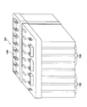
バッテリ100の概略構成を図2の断面図に示す。図2は,図1に示したバッテリパックBPからバッテリ100を取り出して描いたものである。電池容器110は,図2に示すように,電池容器本体120と,封口板130とを備えるものである。電池容器110の内部には,捲回電極体10が配置されている。この捲回電極体10は,実際に発電に寄与する発電要素である。封口板130は,電池容器本体120の開口部を塞ぐためのものである。そのため,電池容器本体120に接合されている。
1-2. Battery Cell A schematic configuration of the
電池容器110の内部には,電解液が注入されている。この電解液は,有機溶媒に電解質を溶解させたものである。有機溶媒として例えば,プロピレンカーボネート(PC),エチレンカーボネート(EC),ジメチルカーボネート(DMC),ジエチルカーボネート(DEC),エチルメチルカーボネート(EMC),1,2−ジメトキシエタン,1,2−ジエトキシエタン,テトラヒドロフラン,2−メチルテトラヒドロフラン,ジオキサン,1,3−ジオキソラン,エチレングリコールジメチルエーテル,ジエチレングリコールジメチルエーテル,アセトニトリル,プロピオニトリル,ニトロメタン,N,N−ジメチルホルムアミド,ジメチルスルホキシド,スルホラン,γ−ブチロラクトン等の非水系溶媒またはこれらを組み合わせた溶媒を用いることができる。
An electrolyte is injected into the
また,電解質である塩として,過塩素酸リチウム(LiClO4)やホウフッ化リチウム(LiBF4),六フッ化リン酸リチウム(LiPF6),六フッ化砒酸リチウム(LiAsF6),LiCF3SO3,LiC4F9SO3,LiN(CF3SO2)2,LiC(CF3SO2)3,LiIなどのリチウム塩を用いることができる。 Further, as a salt that is an electrolyte, lithium perchlorate (LiClO 4 ), lithium borofluoride (LiBF 4 ), lithium hexafluorophosphate (LiPF 6 ), lithium hexafluoroarsenate (LiAsF 6 ), LiCF 3 SO 3 , LiC 4 F 9 SO 3, LiN (CF 3 SO 2) 2, LiC (CF 3 SO 2) 3, can be used a lithium salt such as LiI.
図2に示すように,バッテリ100は,正極端子50と,負極端子60と,絶縁部材150と,絶縁部材160とを有している。絶縁部材150は,正極端子50と封口板130とを絶縁するための部材である。絶縁部材160は,負極端子60と封口板130とを絶縁するための部材である。
As shown in FIG. 2, the
図2に示すように,封口板130には注液孔140が設けられている。注液孔140は,封口板130を貫通する貫通孔である。後述する電解液注入工程では,この注液孔140から電解液を電池容器110の内部に注入する。また,注液孔140の内壁の内側には,何も充填されていない。すなわち,空洞である。注液孔140の内壁の内側には,一旦注液孔を封止する仮封止部材は設けられていない。後述するように,本形態における電池の製造方法では,仮封止をする必要がないからである。蓋体170は,封口板130の注液孔140を塞ぐための注液孔用蓋体である。したがって,蓋体170は,注液孔140の開口部分を覆っている。蓋体170は,封口板130の外側から封口板130にシーム溶接されている。
As shown in FIG. 2, a
1−3.捲回電極体の構造
図3は,溶接前における捲回電極体10を示す斜視図である。図3に示すように,捲回電極体10は扁平形状をしている。捲回電極体10の一方の端部には,正極端部30が突出している。正極端部30は,後述するように,正極板の正極芯材が突出している正極突出部である。捲回電極体10の他方の端部には,負極端部40が突出している。負極端部40は,後述するように,負極板の負極芯材が突出している負極突出部である。このように,正極端部30および負極端部40は,後述する正極板,負極板,セパレータを積層した積層部から突出している。
1-3. FIG. 3 is a perspective view showing the
図4は,捲回電極体10の捲回構造を示す展開図である。捲回電極体10は,図4に示すように,内側から正極板P,セパレータS,負極板N,セパレータTの順に積み重ねた状態で捲回されたものである。すなわち,捲回電極体10は,正極板Pと負極板Nとをこれらの間にセパレータS,Tを介在させて交互に配置したものである。
FIG. 4 is a development view showing a wound structure of the
正極板Pは,正極芯材であるアルミ箔にリチウムイオンを吸蔵・放出可能な正極活物質を含む合材を塗布したものである。正極活物質として,ニッケル酸リチウム(LiNiO2),マンガン酸リチウム(LiMnO2),コバルト酸リチウム(LiCoO2)等のリチウム複合酸化物などが用いられる。負極板Nは,負極芯材である銅箔にリチウムイオンを吸蔵・放出可能な負極活物質を含む合材を塗布したものである。負極活物質として,非晶質炭素,難黒鉛化炭素,易黒鉛化炭素,黒鉛等の炭素系物質が用いられる。 The positive electrode plate P is obtained by applying a composite material containing a positive electrode active material capable of inserting and extracting lithium ions to an aluminum foil as a positive electrode core material. As the positive electrode active material, lithium composite oxides such as lithium nickelate (LiNiO 2 ), lithium manganate (LiMnO 2 ), and lithium cobaltate (LiCoO 2 ) are used. The negative electrode plate N is obtained by applying a composite material containing a negative electrode active material capable of occluding and releasing lithium ions to a copper foil as a negative electrode core material. As the negative electrode active material, carbon-based materials such as amorphous carbon, non-graphitizable carbon, graphitizable carbon, and graphite are used.
図4に示すように正極板Pには,正極塗工部P1と,正極非塗工部P2とがある。正極塗工部P1は,正極芯材に正極活物質等を含む正極合材層を形成した箇所である。正極非塗工部P2は,正極芯材に正極合材層を形成していない箇所である。負極板Nには,負極塗工部N1と,負極非塗工部N2とがある。負極塗工部N1は,負極芯材に負極活物質等を含む負極合材層を形成した箇所である。負極非塗工部N2は,負極芯材に負極合材層を形成していない箇所である。 As shown in FIG. 4, the positive electrode plate P has a positive electrode coating part P1 and a positive electrode non-coating part P2. The positive electrode coating part P1 is a place where a positive electrode mixture layer containing a positive electrode active material or the like is formed on a positive electrode core material. The positive electrode non-coated portion P2 is a portion where the positive electrode mixture layer is not formed on the positive electrode core material. The negative electrode plate N includes a negative electrode coating portion N1 and a negative electrode non-coating portion N2. The negative electrode coating portion N1 is a portion where a negative electrode mixture layer containing a negative electrode active material or the like is formed on a negative electrode core material. The negative electrode non-coated portion N2 is a portion where the negative electrode mixture layer is not formed on the negative electrode core material.
図4中の矢印Aは,正極板P,負極板N,セパレータS,Tの幅方向(図3でいえば横方向)を示している。図4中の矢印Bは,正極板P,負極板N,セパレータS,Tの長手方向(図3の捲回電極体10の周方向)を示している。
An arrow A in FIG. 4 indicates the width direction (lateral direction in FIG. 3) of the positive electrode plate P, the negative electrode plate N, and the separators S and T. An arrow B in FIG. 4 indicates the longitudinal direction of the positive electrode plate P, the negative electrode plate N, the separators S and T (the circumferential direction of the
セパレータS,Tは,ポリエチレンやポリプロピレン等の多孔性フィルムである。セパレータS,Tの厚みは,10〜50μm程度である。ここで,セパレータSとセパレータTとは同じ材質のものである。上記の捲回順の理解のために符号をS,Tとして区別しただけである。 The separators S and T are porous films such as polyethylene and polypropylene. The thicknesses of the separators S and T are about 10 to 50 μm. Here, the separator S and the separator T are made of the same material. For the understanding of the above winding order, only the codes are distinguished as S and T.
図5は,正極板P(もしくは負極板N)の斜視断面図である。図5中の括弧外の各符号は,正極の場合の各部を,括弧内の各符号は,負極の場合の各部を示している。図5中の矢印Aが示す方向は,図4中の矢印Aが示す方向と同じである。すなわち,正極板P(もしくは負極板N)の幅方向である。図5中の矢印Bが示す方向は,図4中の矢印Bが示す方向と同じである。すなわち,正極板P(もしくは負極板N)の長手方向である。 FIG. 5 is a perspective sectional view of the positive electrode plate P (or the negative electrode plate N). In FIG. 5, each symbol outside the parentheses indicates each part in the case of the positive electrode, and each symbol in the parenthesis indicates each part in the case of the negative electrode. The direction indicated by the arrow A in FIG. 5 is the same as the direction indicated by the arrow A in FIG. That is, it is the width direction of the positive electrode plate P (or the negative electrode plate N). The direction indicated by arrow B in FIG. 5 is the same as the direction indicated by arrow B in FIG. That is, it is the longitudinal direction of the positive electrode plate P (or the negative electrode plate N).
図5に示すように,正極板Pは,帯状の正極芯材PBの両面の一部に正極合材層PAが形成されたものである。図5中左側には,正極板Pの正極非塗工部P2が幅方向に突出している。正極非塗工部P2は,帯状に形成されている。正極非塗工部P2は,正極芯材PBの両面ともに正極活物質が塗布されていない領域である。したがって正極非塗工部P2では,正極芯材PBがむき出したままの状態にある。一方,図5中右側には,正極非塗工部P2に対応するような突出部はない。正極塗工部P1では,正極芯材PBの両面に一様の厚みで正極合材層PAが形成されている。 As shown in FIG. 5, the positive electrode plate P is obtained by forming a positive electrode mixture layer PA on a part of both surfaces of a strip-like positive electrode core material PB. On the left side in FIG. 5, the positive electrode non-coated portion P2 of the positive electrode plate P protrudes in the width direction. The positive electrode non-coated portion P2 is formed in a strip shape. The positive electrode non-coated portion P2 is a region where the positive electrode active material is not applied to both surfaces of the positive electrode core material PB. Therefore, in the positive electrode non-coating portion P2, the positive electrode core material PB is still exposed. On the other hand, there is no protrusion corresponding to the positive electrode non-coated portion P2 on the right side in FIG. In the positive electrode coating part P1, the positive electrode mixture layer PA is formed with a uniform thickness on both surfaces of the positive electrode core material PB.
正極合材層PAは,正極芯材PBであるアルミ箔にリチウムイオンを吸蔵・放出可能な正極活物質の他に,導電材,結着材,増粘材を含む合材を塗布して形成された層である。正極活物質として,ニッケル酸リチウム(LiNiO2),マンガン酸リチウム(LiMnO2),コバルト酸リチウム(LiCoO2)等のリチウム複合酸化物などが用いられる。 The positive electrode mixture layer PA is formed by applying a composite material including a conductive material, a binder, and a thickener in addition to the positive electrode active material capable of occluding and releasing lithium ions to the aluminum foil as the positive electrode core material PB. Layer. As the positive electrode active material, lithium composite oxides such as lithium nickelate (LiNiO 2 ), lithium manganate (LiMnO 2 ), and lithium cobaltate (LiCoO 2 ) are used.
正極用の導電材として,カーボン粉末やカーボンファイバー等のカーボン材料を用いることができる。例えば,アセチレンブラック,ファーネスブラック,ケッチェンブラック等のカーボンブラック,グラファイト粉末,などのカーボン粉末である。 Carbon materials such as carbon powder and carbon fiber can be used as the conductive material for the positive electrode. For example, carbon powder such as acetylene black, furnace black, ketjen black, etc., graphite powder, etc.
正極用の結着材は,電解液に不溶性(または難溶性)であって,正極用ペーストに用いる溶媒に分散するポリマーであるとよい。例えば,ポリフッ化ビニリデン(PVDF),ポリテトラフルオロエチレン(PTFE),テトラフルオロエチレン−パーフルオロアルキルビニルエーテル共重合体(PFA),テトラフルオロエチレン−ヘキサフルオロプロピレン共重合体(FEP),エチレン−テトラフルオロエチレン共重合体(ETFE)等のフッ素系樹脂,酢酸ビニル共重合体,スチレンブタジエンゴム(SBR),アクリル酸変性SBR樹脂(SBR系ラテックス),アラビアゴム等のゴムを用いることができる。または,これらの組み合わせを用いてもよい。結着材は,必ずしも上記のポリマーに限定されない。 The binder for the positive electrode is preferably a polymer that is insoluble (or hardly soluble) in the electrolyte and is dispersed in the solvent used for the positive electrode paste. For example, polyvinylidene fluoride (PVDF), polytetrafluoroethylene (PTFE), tetrafluoroethylene-perfluoroalkyl vinyl ether copolymer (PFA), tetrafluoroethylene-hexafluoropropylene copolymer (FEP), ethylene-tetrafluoro Fluorine resin such as ethylene copolymer (ETFE), vinyl acetate copolymer, styrene butadiene rubber (SBR), acrylic acid-modified SBR resin (SBR latex), rubber such as gum arabic can be used. Alternatively, a combination of these may be used. The binder is not necessarily limited to the above polymer.
正極用の増粘材として,カルボキシメチルセルロース(CMC),メチルセルロース(MC),酢酸フタル酸セルロース(CAP),ヒドロキシプロピルメチルセルロース(HPMC),ヒドロキシプロピルメチルセルロースフタレート(HPMCP)等のセルロースが用いられる。ただし,必ずしも上記したようなセルロースに限らず用いることができる。 As the thickener for the positive electrode, cellulose such as carboxymethylcellulose (CMC), methylcellulose (MC), cellulose acetate phthalate (CAP), hydroxypropylmethylcellulose (HPMC), hydroxypropylmethylcellulose phthalate (HPMCP) or the like is used. However, it is not necessarily limited to cellulose as described above, and can be used.
溶媒として,水が挙げられる。その他に,N−メチル−2−ピロリドン(NMP,以下NMPという)を用いてもよい。また,その他の低級アルコールや低級ケトンを用いることもできる。 An example of the solvent is water. In addition, N-methyl-2-pyrrolidone (NMP, hereinafter referred to as NMP) may be used. Other lower alcohols and lower ketones can also be used.
図5の括弧内の符号で示すように,負極板Nは,帯状の負極芯材NBの両面の一部に負極合材層NAが形成されたものである。図5中左側には,負極板Nの負極非塗工部N2が幅方向に突出している。負極非塗工部N2は,帯状に形成されている。負極非塗工部N2は,負極芯材NBの両面ともに負極活物質が塗布されていない領域である。したがって負極非塗工部N2では,負極芯材NBがむき出したままの状態にある。一方,図5中右側には,負極非塗工部N2に対応するような突出部はない。負極塗工部N1では,負極芯材NBの両面に一様の厚みで負極合材層NAが形成されている。ただし,図4に示したように,捲回時には,正極非塗工部P2と負極非塗工部N2とは,反対側に突出した状態で捲回されることとなる。 As indicated by the reference numerals in parentheses in FIG. 5, the negative electrode plate N is obtained by forming a negative electrode mixture layer NA on a part of both surfaces of a strip-shaped negative electrode core material NB. On the left side in FIG. 5, a negative electrode non-coated portion N2 of the negative electrode plate N protrudes in the width direction. The negative electrode non-coated portion N2 is formed in a strip shape. The negative electrode non-coated portion N2 is a region where the negative electrode active material is not applied to both surfaces of the negative electrode core material NB. Therefore, in the negative electrode non-coating portion N2, the negative electrode core material NB is still exposed. On the other hand, there is no protrusion corresponding to the negative electrode non-coated portion N2 on the right side in FIG. In the negative electrode coating portion N1, the negative electrode mixture layer NA is formed with a uniform thickness on both surfaces of the negative electrode core material NB. However, as shown in FIG. 4, at the time of winding, the positive electrode non-coated portion P2 and the negative electrode non-coated portion N2 are wound in a state of protruding to the opposite side.
負極合材層NAは,負極芯材NBである銅箔に負極活物質,結着材,増粘材を含む合材を塗布して乾燥させた層である。負極活物質は,リチウムイオンを吸蔵・放出可能な物質である。負極活物質として,少なくとも一部にグラファイト構造を含む炭素系物質が用いられる。例えば,非晶質炭素,難黒鉛化炭素(ハードカーボン),易黒鉛化炭素(ソフトカーボン),黒鉛(グラファイト),またはこれらを組み合わせた構造を有する炭素材料を用いることができる。 The negative electrode mixture layer NA is a layer obtained by applying a mixture containing a negative electrode active material, a binder, and a thickener to a copper foil as the negative electrode core material NB and drying it. The negative electrode active material is a material that can occlude and release lithium ions. As the negative electrode active material, a carbon-based material containing a graphite structure at least partially is used. For example, amorphous carbon, non-graphitizable carbon (hard carbon), graphitizable carbon (soft carbon), graphite (graphite), or a carbon material having a combination thereof can be used.
負極用の結着材は,電解液に不溶性(または難溶性)であって,負極用ペーストに用いる溶媒に分散するポリマーであるとよい。例えば,ポリフッ化ビニリデン(PVDF),ポリテトラフルオロエチレン(PTFE),テトラフルオロエチレン−パーフルオロアルキルビニルエーテル共重合体(PFA),テトラフルオロエチレン−ヘキサフルオロプロピレン共重合体(FEP),エチレン−テトラフルオロエチレン共重合体(ETFE)等のフッ素系樹脂,酢酸ビニル共重合体,スチレンブタジエンゴム(SBR),アクリル酸変性SBR樹脂(SBR系ラテックス),アラビアゴム等のゴムを用いることができる。または,これらの組み合わせを用いてもよい。結着材は,必ずしも上記のポリマーに限定されない。 The binder for the negative electrode may be a polymer that is insoluble (or hardly soluble) in the electrolyte and is dispersed in the solvent used for the negative electrode paste. For example, polyvinylidene fluoride (PVDF), polytetrafluoroethylene (PTFE), tetrafluoroethylene-perfluoroalkyl vinyl ether copolymer (PFA), tetrafluoroethylene-hexafluoropropylene copolymer (FEP), ethylene-tetrafluoro Fluorine resin such as ethylene copolymer (ETFE), vinyl acetate copolymer, styrene butadiene rubber (SBR), acrylic acid-modified SBR resin (SBR latex), rubber such as gum arabic can be used. Alternatively, a combination of these may be used. The binder is not necessarily limited to the above polymer.
負極用の増粘材として,カルボキシメチルセルロース(CMC),メチルセルロース(MC),酢酸フタル酸セルロース(CAP),ヒドロキシプロピルメチルセルロース(HPMC),ヒドロキシプロピルメチルセルロースフタレート(HPMCP)等のセルロースが用いられる。ただし,必ずしも上記したようなセルロースに限らず用いることができる。 As the thickener for the negative electrode, cellulose such as carboxymethylcellulose (CMC), methylcellulose (MC), cellulose acetate phthalate (CAP), hydroxypropylmethylcellulose (HPMC), hydroxypropylmethylcellulose phthalate (HPMCP) or the like is used. However, it is not necessarily limited to cellulose as described above, and can be used.
溶媒として,水が挙げられる。NMPを用いてもよい。また,その他の低級アルコールや低級ケトンを用いることもできる。 An example of the solvent is water. NMP may be used. Other lower alcohols and lower ketones can also be used.
2.溶接体
2−1.溶接体の基本構成
本形態の溶接体20を図6に示す。図6は,図2のCC断面を示す断面図である。図6では,正極芯材PB(負極芯材NB)を簡略化して描いてある。以降の図でも同様である。溶接体20は,図6に示すように,捲回電極体10と,正極端子50と,負極端子60とを有している。
2. Welded body 2-1. Basic Configuration of Welded Body A welded body 20 of this embodiment is shown in FIG. FIG. 6 is a cross-sectional view showing the CC cross section of FIG. In FIG. 6, the positive electrode core material PB (negative electrode core material NB) is depicted in a simplified manner. The same applies to the subsequent drawings. As shown in FIG. 6, the welded body 20 includes a
図2に示すように,捲回電極体10の正極端部30は,正極端子50に溶接されている。その溶接されている位置は,溶接箇所71および溶接箇所72の2箇所である。正極端部30は,正極合材層PAと電気的に接続されている。したがって,正極端子50は,正極端部30を介して正極合材層PAと電気的に接続されている。
As shown in FIG. 2, the
一方,捲回電極体10の負極端部40は,負極端子60に溶接されている。その溶接されている位置は,溶接箇所81および溶接箇所82の2箇所である。負極端部40は,負極合材層NAと電気的に接続されている。したがって,負極端子60は,負極端部40を介して負極合材層NAと電気的に接続されている。
On the other hand, the
2−2.溶接体における溶接箇所周辺
ここで,溶接体20における溶接箇所71,72の周辺について説明する。また,溶接体20の正極端部30には,図6に示すような隙間70が空いている。この隙間70は,溶接箇所71と溶接箇所72との間に位置している。この隙間70は,後述する溶接方法により,形成されたものである。同様に,負極側の隙間80は,溶接箇所81と溶接箇所82との間に位置している。
2-2. Here, the periphery of the welded
図7に,溶接箇所71と溶接箇所72との間の溶接箇所間距離Lを示す。溶接箇所間距離Lは,溶接箇所71の内側の端部71aと溶接箇所72の内側の端部72aとの間の距離である。
In FIG. 7, the distance L between the welding locations between the
また,正極端部30における,正極端子50から最も遠い位置に位置している正極芯材PBを,最外箔(最外芯材)PXということとする。そして,端部71aから端部72aまでにわたる最外箔PXの長さを最外箔長(最外芯材長)Xということとする。最外箔PXは,外側に,すなわち正極端子50から遠ざかる向きに膨らんで湾曲している。そのため,最外箔長Xは,溶接箇所間距離Lよりも長い。そして,最外箔長Xは,溶接箇所間距離Lに対して,次式の範囲内にあるとよい。
1.05 ≦ X/L ≦ 1.20 ………(1)
Further, the positive electrode core material PB located at the position farthest from the
1.05 ≦ X / L ≦ 1.20 (1)
このように,最外箔長Xは,溶接箇所間距離Lよりも長い。後述する溶接方法により,予め膨らむようにして,溶接されているからである。そのため,最外箔PXには,それほど大きな張力がかかることはない。したがって,最外箔PXが切れるおそれはほとんどない。なお,負極側においても同様である。 As described above, the outermost foil length X is longer than the distance L between the welding locations. This is because it is welded so as to swell in advance by a welding method described later. For this reason, the outermost foil PX is not subjected to such a large tension. Therefore, there is almost no possibility that the outermost foil PX will break. The same applies to the negative electrode side.
3.溶接方法
3−1.スペーサ
続いて,本形態の溶接方法について説明する。本形態の溶接方法は,捲回電極体10の正極端部30および負極端部40をそれぞれ,正極端子50および負極端子60に溶接する方法である。本形態の溶接方法は,正極側でも負極側でも同様である。したがって,これらを代表して,正極側について説明する。
3. Welding method 3-1. Spacer Next, the welding method of this embodiment will be described. The welding method of this embodiment is a method of welding the
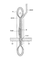
本形態の溶接方法では,図8に示すようなスペーサMを用いる。スペーサMは,捲回電極体10を正極端子50に溶接する前に,正極端部30に挿入される絶縁部材である。なお,後述するように,スペーサMは,溶接時においても正極端部30に挿入されたままである。スペーサMは,板状の部材である。そして,スペーサMの角部M1は,丸面取りされているとよい。なお,スペーサMの厚みは,H1である。
In the welding method of this embodiment, a spacer M as shown in FIG. 8 is used. The spacer M is an insulating member that is inserted into the
3−2.絶縁部材挿入工程
次に,図9に示すように,1枚のスペーサMを正極端部30に挿入する。その挿入箇所は,捲回電極体10の捲回中心付近であるとよい。ただし,捲回中心付近からずれた箇所に挿入することとしてもよい。正極端部30は,捲回電極体10から突出している正極非塗工部P2である。そのため,正極端部30には,セパレータS,Tや負極板N,正極合材層PA等の厚みに相当する隙間が空いている。したがって,スペーサMの挿入は容易である。このスペーサMの挿入により,隙間70が形成される。
3-2. Next, as shown in FIG. 9, one spacer M is inserted into the
3−3.溶接工程
続いて,正極端部30を正極端子50に抵抗溶接する。このとき,スペーサMは,隙間70に挿入されたままである。まず,図10に示すように,正極端部30を正極端子50に押圧する。そのため,正極端部30は,捲回電極体10の厚み方向につぶれる。ここで,押圧時における正極端部30の押圧箇所の厚みをHとする。
3-3. Next, the positive
続いて,電極E1,E2で,溶接を予定されている溶接箇所71を挟み込む。そして,電極E1,E2で溶接箇所71を挟み込んだ状態で,電極E1,E2間に電圧を印加する。スペーサMは絶縁部材であるため,抵抗溶接の際にスペーサMの箇所には電流は流れない。そのため,溶接不良は生じにくい。これにより,正極端部30の溶接箇所71は,好適に溶接される。つまり,スペーサMを正極端部30に挟みつつ,抵抗溶接を行うのである。次に,図11に示すように,溶接箇所72も溶接する。そして,溶接終了後に,スペーサMを正極端部30から引き抜く。負極についても,同様に溶接を行う。これにより,図7に示した溶接体20が製造される。
Subsequently, a
4.電池の製造方法
ここで,本実施の形態に係る電池の製造方法について説明する。本形態の電池の製造方法は,次に示すように,電極板作成工程と,電極体作成工程と,溶接体作成工程と,電池組立工程とを有する方法である。そして,本形態の電池の製造方法は,溶接体作成工程において,前述の溶接方法を用いることに特徴点を有する。
(A)電極板作成工程
(B)電極体作成工程
(C)溶接体作成工程
(D)電池組立工程
4). Battery Manufacturing Method Here, a battery manufacturing method according to the present embodiment will be described. The battery manufacturing method of the present embodiment is a method having an electrode plate creation process, an electrode body creation process, a welded body creation process, and a battery assembly process, as shown below. And the manufacturing method of the battery of this form has the feature point in using the above-mentioned welding method in a welding body preparation process.
(A) Electrode plate creation process (B) Electrode body creation process (C) Welded body creation process (D) Battery assembly process
4−1.(A)電極板作成工程
まず,正極芯材PBであるアルミニウム箔に正極用塗工液を塗工して正極用ペースト層とする。この正極用塗工液は,溶媒に上記の正極活物質等を混練したものである。次に,正極用ペースト層の形成された正極芯材PBを乾燥炉の内部に搬送しつつその正極用ペースト層を乾燥させる。これにより,正極芯材PBに正極合材層PAが形成される。正極合材層PAは,正極活物質を含む層である。なお,正極芯材PBの両面に正極合材層PAを形成することが好ましい。これにより,正極板Pが作成される。負極板Nについても同様である。
4-1. (A) Electrode plate preparation process First, the positive electrode coating liquid is applied to the aluminum foil that is the positive electrode core material PB to form a positive electrode paste layer. This positive electrode coating solution is obtained by kneading the above positive electrode active material or the like in a solvent. Next, the positive electrode paste layer on which the positive electrode paste layer is formed is dried while being conveyed into the drying furnace. Thereby, the positive electrode mixture layer PA is formed on the positive electrode core material PB. The positive electrode mixture layer PA is a layer containing a positive electrode active material. The positive electrode mixture layer PA is preferably formed on both surfaces of the positive electrode core material PB. Thereby, the positive electrode plate P is created. The same applies to the negative electrode plate N.
4−2.(B)電極体作成工程
続いて,捲回電極体10を作成する。その際に,図4に示したように,正極板Pおよび負極板Nに,これらの間にセパレータS,Tを介在させて捲回する。これにより,円筒形状の捲回電極体が作成される。この円筒形状の捲回電極体を円筒側面方向から圧縮することにより,図3に示したような扁平形状の捲回電極体10が作成される。
4-2. (B) Electrode body creation process Subsequently, the
4−3.(C)溶接体作成工程
続いて,前述の溶接方法を用いて,捲回電極体10の正極端部30および負極端部40をそれぞれ,正極端子50および負極端子60に溶接する。これにより,図6に示した溶接体20が作成される。前述したように,溶接体20において,箔切れや箔潰れは,ほとんど起きていない。
4-3. (C) Welded body preparation step Subsequently, the
4−4.(D)電池組立工程
次に,溶接体20を電池容器本体120に収容する。また,封口板130を電池容器本体120に接合する。この接合にレーザ溶接を用いるとよい。もちろん,その他の接合方法を用いてもよい。そして,注液孔140から電池容器本体120の内部に電解液を注入する。次に,蓋体170を封口板130に接合する。これにより,バッテリ100が組み立てられる。
4-4. (D) Battery Assembly Step Next, the welded body 20 is accommodated in the
4−5.その他の工程
電池容器110の内部に電解液を注入した後,電解液は捲回電極体10の正極合材層PAおよび負極合材層NAに徐々に含浸していく。この電解液の含浸後に,初期充電工程や高温エージング工程等を施すこととするとよい。また,その他の各種の検査工程を行ってもよい。以上の工程を経ることにより,本形態のバッテリ100が製造される。
4-5. Other Steps After injecting the electrolytic solution into the
5.変形例
5−1.複数枚のスペーサ
ここで,本形態の変形例について説明する。本形態では,正極端部30や負極端部40に,スペーサMを1枚だけ挟んだ状態で溶接を行うこととした。しかし,厚みの薄い複数枚のスペーサを,正極端部30や負極端部40に挟んだ状態で溶接を行うこととしてもよい。
5. Modified example 5-1. Multiple spacers Here, a modification of this embodiment will be described. In this embodiment, welding is performed with only one spacer M sandwiched between the
具体的には,正極芯材PBもしくは負極芯材NBの所定の枚数毎にスペーサを挟むこととするのである。例えば,正極芯材PBもしくは負極芯材NBが3枚毎や5枚毎にスペーサを挟むことができる。複数のスペーサにおける各々の挿入箇所は,互いに異なっている箇所である。隙間70(80)よりも幅の狭い隙間が多数形成されることとなる。そのため,電解液は正極合材層PAおよび負極合材層NAに含浸しやすい。この場合における含浸速度は,本形態における含浸速度よりも速い。したがって,バッテリ100の生産性は向上する。
Specifically, the spacer is sandwiched every predetermined number of positive electrode core materials PB or negative electrode core materials NB. For example, the spacer can be sandwiched between every three or every five positive electrode core materials PB or negative electrode core materials NB. Each insertion location in the plurality of spacers is different from each other. Many gaps narrower than the gap 70 (80) will be formed. Therefore, the electrolytic solution easily impregnates the positive electrode mixture layer PA and the negative electrode mixture layer NA. The impregnation rate in this case is faster than the impregnation rate in this embodiment. Therefore, the productivity of the
5−2.電極体の形状
本形態では,扁平形状の捲回電極体10を備えるリチウムイオン二次電池の製造方法について説明した。しかし,扁平形状の捲回電極体10を有する電池に限らない。捲回しないで正極板と負極板とを平積みした電極体を用いる電池にも適用することができる。その他,正極板と負極板とを積層した積層電極体を備えるとともに,正極側の集電部と負極側の集電部とが,電極体から突出している電極体を有する電池であれば適用可能である。
5-2. Shape of Electrode Body In this embodiment, a method for manufacturing a lithium ion secondary battery including the flat
5−3.電池の種類
また,リチウムイオン二次電池に限らない。その他の電池であっても,電極端子と発電要素とを複数個所で溶接した溶接体を有する電池であれば,同様に適用することができる。その場合の電極体の構成は,リチウムイオン二次電池の電極体の構成と異なっている。したがって,電極板作成工程は必ずしも必要ではない場合がある。もちろん,そのような電池であっても,発電要素である電極体は必要である。
5-3. Battery type Not limited to lithium ion secondary batteries. Other batteries can be similarly applied as long as they have a welded body in which electrode terminals and power generating elements are welded at a plurality of locations. In this case, the configuration of the electrode body is different from that of the lithium ion secondary battery. Therefore, the electrode plate creation process may not be necessary. Of course, even such a battery requires an electrode body as a power generation element.
6.まとめ
以上,詳細に説明したように,本実施の形態に係る電池の製造方法では,捲回電極体10を正極端子50や負極端子60に溶接する際に,捲回電極体10の正極端部30や負極端部40にスペーサMを挿入することとした。そのため,正極端子50もしくは負極端子60から遠い位置にある最外箔PX等に強い張力がかかることはない。したがって,溶接時に,箔切れや箔潰れが生じることがほとんどない電池の製造方法が実現されている。つまり,歩留まりはよい。
6). Summary As described above in detail, in the method for manufacturing a battery according to the present embodiment, when the
また,本形態のバッテリ100は,溶接体20を有している。溶接体20では,最外箔PXの長さXが,溶接箇所間距離Lよりも長い。したがって,捲回電極体10の最外箔PX等に強い張力が加わることはほとんどない。よって,電池の製造後においても,箔切れや箔潰れの生じにくい電池が実現されている。
Further, the
なお,本実施の形態は単なる例示にすぎず,本発明を何ら限定するものではない。したがって本発明は当然に,その要旨を逸脱しない範囲内で種々の改良,変形が可能である。例えば,電池であれば,二次電池に限らず,一次電池にも適用することができる。また,本形態では,電極体と電極端子との溶接箇所を2箇所とした。しかし,3箇所以上溶接を行うこととしてもよい。また,スペーサMを捲回電極体に挿入する挿入箇所を,正極側もしくは負極側のいずれかとしてもよい。 Note that this embodiment is merely an example, and does not limit the present invention. Therefore, the present invention can naturally be improved and modified in various ways without departing from the gist thereof. For example, if it is a battery, it can apply not only to a secondary battery but to a primary battery. In this embodiment, the number of welded portions between the electrode body and the electrode terminal is two. However, three or more locations may be welded. Further, the insertion position where the spacer M is inserted into the wound electrode body may be either the positive electrode side or the negative electrode side.
(第2の実施形態)
第2の実施形態について説明する。本形態では,用いる電極端子の形状が第1の実施形態と異なっている。したがって,以下,異なる点のみについて説明する。
(Second Embodiment)
A second embodiment will be described. In this embodiment, the shape of the electrode terminal used is different from that of the first embodiment. Therefore, only different points will be described below.
1.溶接体
1−1.電極端子の形状
本形態における正極端子250(負極端子260)の形状および溶接体220を図12に示す。図12に示すように,正極端子250には,凹部251が形成されている。凹部251は,溶接後に捲回電極体10と対面する側の面に形成されている。そして,正極端子250における凹部251の反対側の面には,凸部252が形成されている。
1. Welded body 1-1. Shape of Electrode Terminal FIG. 12 shows the shape of the positive electrode terminal 250 (negative electrode terminal 260) and the welded
1−2.溶接体における溶接箇所周辺
ここで,溶接体20における溶接箇所71,72の周辺について説明する。図12に示すように,溶接体220の正極端部30には,隙間270が空いている。隙間270は,第1の実施形態における隙間70とほぼ同様のものである。
1-2. Here, the periphery of the welded
また,正極端部30における,正極端子50から最も近い位置に位置している正極芯材PBを,最内箔(最内芯材)PYということとする。そして,端部71aから端部72aまでにわたる最内箔PYの長さを最内箔長(最内芯材長)Yということとする。最内箔PYは,正極端子50に向かう向きに膨らんで湾曲している。そのため,最内箔長Yは,溶接箇所間距離Lよりも長い。そして,最内箔長Yは,溶接箇所間距離Lに対して,次式の範囲内にあるとよい。
1.05 ≦ Y/L ≦ 1.20 ………(2)
In addition, the positive electrode core material PB located at the position closest to the
1.05 ≦ Y / L ≦ 1.20 (2)
式(2)に示すように,最内箔長Yは,溶接箇所間距離Lよりも長い。前述した溶接方法により,予め膨らむようにして,溶接されているからである。そのため,最内箔PYには,それほど大きな張力がかかることはない。したがって,最内箔PYが切れるおそれはほとんどない。 As shown in the formula (2), the innermost foil length Y is longer than the distance L between the welding locations. This is because welding is performed in advance by the above-described welding method. For this reason, the innermost foil PY is not subjected to such a large tension. Therefore, there is almost no possibility that the innermost foil PY is cut.
なお,本形態では,式(1)をも満たしうる。したがって,最外箔PXにも,それほど大きな張力がかかることはない。したがって,最外箔PXが切れるおそれはほとんどない。また,負極についても同様である。 In the present embodiment, equation (1) can also be satisfied. Accordingly, the outermost foil PX is not so much tensioned. Therefore, there is almost no possibility that the outermost foil PX will break. The same applies to the negative electrode.
2.変形例
2−1.電極端子の形状(1)
本形態では,凹部251と凸部252とが形成された電極端子250,260を用いることとした。しかし,本形態とは異なる形状の電極端子を用いることもできる。例えば,図13に示す電極端子350,360を用いてもよい。電極端子350,360には,凹部351,361が形成されている。この場合であっても,最内箔長Yは,溶接箇所間距離Lよりも長いことに変わりないからである。
2. Modification 2-1. Electrode terminal shape (1)
In this embodiment, the
2−2.電極端子の形状(2)
また,図14に示す電極端子450,460を用いてもよい。電極端子450,460では,なだらかな凹部451,461が形成されている。この場合であっても,最内箔長Yは,溶接箇所間距離Lよりも長いことに変わりないからである。
2-2. Electrode terminal shape (2)
Moreover, you may use the
3.まとめ
以上,詳細に説明したように,本実施の形態に係る電池の製造方法では,捲回電極体10を正極端子50や負極端子60に溶接する際に,捲回電極体10の正極端部30や負極端部40にスペーサMを挿入することとした。そのため,正極端子50もしくは負極端子60から最も遠い位置にある最外箔PXに強い張力がかかることはない。さらに,最内箔PYに強い張力がかかることもほとんどない。したがって,溶接時に,箔切れや箔潰れが生じることがほとんどない電池の製造方法が実現されている。つまり,歩留まりはよい。
3. Summary As described above in detail, in the method for manufacturing a battery according to the present embodiment, when the
また,本形態のバッテリ100は,溶接体20を有している。溶接体20では,最外箔PXの長さXが,溶接箇所間距離Lよりも長い。したがって,捲回電極体10の最外箔PXに強い張力が加わることはほとんどない。そして,最内箔長Yは,溶接箇所間距離Lよりも長い。したがって,捲回電極体10の最内箔PYに強い張力が加わることはほとんどない。よって,電池の製造後においても,箔切れや箔潰れの生じにくい電池が実現されている。
Further, the
なお,本実施の形態は単なる例示にすぎず,本発明を何ら限定するものではない。したがって本発明は当然に,その要旨を逸脱しない範囲内で種々の改良,変形が可能である。例えば,電池であれば,二次電池に限らず,一次電池にも適用することができる。また,本形態では,電極体と電極端子との溶接箇所を2箇所とした。しかし,3箇所以上溶接を行うこととしてもよい。また,スペーサMを捲回電極体に挿入する挿入箇所を,正極側もしくは負極側のいずれかとしてもよい。 Note that this embodiment is merely an example, and does not limit the present invention. Therefore, the present invention can naturally be improved and modified in various ways without departing from the gist thereof. For example, if it is a battery, it can apply not only to a secondary battery but to a primary battery. In this embodiment, the number of welded portions between the electrode body and the electrode terminal is two. However, three or more locations may be welded. Further, the insertion position where the spacer M is inserted into the wound electrode body may be either the positive electrode side or the negative electrode side.
A.実験1
A−1.実験方法
ここで,第1の実施形態で説明したように,スペーサを用いて製造したバッテリに関する実験について説明する。この実験は,捲回電極体を電極端子に溶接する際に,スペーサを挟んで溶接した電池と,スペーサを挟まずに溶接した電池との違いを比較するために行ったものである。なお,実施形態1で説明したように,捲回電極体にスペーサを1枚だけ挟んだ状態で溶接を行った。
A. Experiment 1
A-1. Experimental Method Here, as described in the first embodiment, an experiment related to a battery manufactured using a spacer will be described. This experiment was conducted in order to compare the difference between a battery welded with a spacer and a battery welded without a spacer when welding the wound electrode body to the electrode terminal. As described in the first embodiment, welding was performed with only one spacer sandwiched between the wound electrode bodies.
この実験に際して変化させたパラメータは,次に示すものである。
1−1)スペーサの有無
1−2)スペーサの厚みH1
ここで,スペーサの厚みH1は,図8に示したものである。
The parameters changed in this experiment are as follows.
1-1) Presence / absence of spacer 1-2) Spacer thickness H1
Here, the thickness H1 of the spacer is as shown in FIG.
A−2.評価項目
評価項目は,次のとおりである。
2−1)箔切れの枚数
2−2)箔潰れの有無
A-2. Evaluation items Evaluation items are as follows.
2-1) Number of foil breaks 2-2) Presence of foil crushing
ここで,箔切れの有無を,溶接後の溶接体の捲回電極体に,正極芯材もしくは負極芯材の箔が切れているか否かを調べた。箔切れの枚数は,正極芯材と負極芯材との合計の枚数である。正極端部30もしくは負極端部40の箔が折れ曲がって潰れている場合に,箔潰れが生じているとした。
Here, whether the foil of the positive electrode core material or the negative electrode core material was cut in the wound electrode body of the welded body after welding was checked for the presence or absence of foil breakage. The number of pieces of foil is the total number of the positive electrode core material and the negative electrode core material. When the foil of the positive
A−3.実験結果
実験1の結果を,表1に示す。ここでHは,溶接前に正極端部30(負極端部40)を正極端子50(負極端子60)に押圧したときの正極端部30(負極端部40)の厚みである(図9等参照)。表1の実施例1,2に示すように,スペーサの厚みH1を,次式を満たす範囲内とすればよい。
H/6 ≦ H1 ≦ H/3 ………(3)
すなわち,スペーサの厚みH1を,押圧後の正極端部30(負極端部40)の厚みHの6分の1から3分の1までの範囲内とするとよい。
A-3. Experimental results Table 1 shows the results of Experimental 1. Here, H is the thickness of the positive electrode end 30 (negative electrode end 40) when the positive electrode end 30 (negative electrode end 40) is pressed against the positive electrode terminal 50 (negative electrode terminal 60) before welding (FIG. 9 and the like). reference). As shown in Examples 1 and 2 in Table 1, the thickness H1 of the spacer may be within a range that satisfies the following expression.
H / 6 ≦ H1 ≦ H / 3 (3)
In other words, the thickness H1 of the spacer is preferably in the range from 1/6 to 1/3 of the thickness H of the positive electrode end 30 (negative electrode end 40) after pressing.
表1の比較例1に示すように,スペーサを挟まないで溶接を行った場合には,箔切れの枚数も多く,箔潰れも生じている。また,比較例2のようにスペーサを挟んだ場合であっても,スペーサの厚みH1が薄すぎると,箔切れや箔潰れが生じる。最外箔等に加わる張力を緩和する効果が小さいためである。一方,比較例3のようにスペーサの厚みH1が厚すぎると,箔切れが生じる。溶接時に電極E1,E2で正極端部30(負極端部40)を挟む際に,最外箔に大きな張力が加わるからである。ただし,最外箔は膨らんだ状態にあるので,箔潰れは生じない。 As shown in Comparative Example 1 of Table 1, when welding is performed without sandwiching the spacer, the number of pieces of foil is large and the foil is crushed. Even when the spacer is sandwiched as in Comparative Example 2, if the thickness H1 of the spacer is too thin, the foil may be cut or crushed. This is because the effect of relaxing the tension applied to the outermost foil or the like is small. On the other hand, if the spacer thickness H1 is too thick as in the comparative example 3, the foil breaks. This is because a large tension is applied to the outermost foil when the positive electrode end 30 (negative electrode end 40) is sandwiched between the electrodes E1 and E2 during welding. However, since the outermost foil is in a swelled state, the foil does not collapse.

B.実験2
B−1.実験方法
続いて,実験2について説明する。実験2では,第1の実施形態の変形例で説明したように,溶接を行う際に複数枚のスペーサを挟む場合について実験を行った。この実験に際して変化させたパラメータは,次に示すものである。
1−1)スペーサの有無
1−2)溶接長J(端子長Iとの比)
1−3)スペーサ間に挟む箔の枚数
B. Experiment 2
B-1. Experimental Method Next, Experiment 2 will be described. In Experiment 2, as described in the modification of the first embodiment, an experiment was performed in the case where a plurality of spacers were sandwiched during welding. The parameters changed in this experiment are as follows.
1-1) Presence / absence of spacer 1-2) Weld length J (compared to terminal length I)
1-3) Number of foils sandwiched between spacers
スペーサの有無については,実験1と同様である。溶接長Jとは,図7に示した溶接幅J1と溶接幅J2との和である。つまり,溶接幅J1と溶接幅J2について,正極端子50等の長手方向の長さを足し合わせた合計の長さである。なお,溶接長Jを端子長Iとの比で表している。端子長Iとは,電極端子50,60における捲回電極体10と接触する長さのことである(図7の矢印I参照)。スペーサ間に挟む箔の枚数とは,2枚のスペーサで挟み込む箔の枚数を示している。つまり,一定の箔の枚数毎に,スペーサを挿入しているのである。
The presence or absence of the spacer is the same as in Experiment 1. The weld length J is the sum of the weld width J1 and the weld width J2 shown in FIG. That is, the total length of the weld width J1 and the weld width J2 is the sum of the lengths in the longitudinal direction of the
なお,複数のスペーサの厚みを合計した合計厚みH2は,実験1で箔切れや箔つぶれの生じないとの結果が得られたH/3とした。つまり,合計厚みH2は,式(3)を満たす。したがって後述するように,実施例3〜実施例14では,箔切れや箔潰れは生じていない。 The total thickness H2 obtained by summing the thicknesses of the plurality of spacers was set to H / 3, which was obtained in Experiment 1 so that no foil breakage or foil collapse occurred. That is, the total thickness H2 satisfies the formula (3). Therefore, as will be described later, in Examples 3 to 14, no foil breakage or foil crushing occurs.
B−2.評価項目
評価項目は,次のとおりである。
2−1)箔切れの枚数
2−2)箔潰れの有無
2−3)含浸完了時間
B-2. Evaluation items Evaluation items are as follows.
2-1) Number of foil breaks 2-2) Foil crushing 2-3) Impregnation completion time
箔切れ枚数および箔潰れの有無については,実験1の場合と同様の方法で評価している。含浸完了時間とは,電解液が捲回電極体の正極合材層および負極合材層に含浸する含浸が完了するまでに要する時間のことである。実際には,電解液注入後の電池の内部抵抗を測定し,その内部抵抗の値が一定値に収束するまでの時間を採用した。 The number of pieces of foil and the presence or absence of foil crushing are evaluated by the same method as in Experiment 1. The impregnation completion time is the time required for the impregnation of the electrolyte solution into the positive electrode mixture layer and the negative electrode mixture layer of the wound electrode body to be completed. Actually, the internal resistance of the battery after electrolyte injection was measured, and the time until the internal resistance converged to a constant value was adopted.
B−3.実験結果
B−3−1.箔切れおよび箔潰れ
実験2の結果を,表2に示す。表2に示すように,スペーサを用いて溶接した実施例3〜実施例14には,箔切れおよび箔潰れは生じない。これは,実験1の実験結果と矛盾しない。そして,スペーサを用いないで溶接を行った比較例4〜比較例7では,箔切れが生じている。そして,比較例5〜比較例7では,箔潰れが生じている。
B-3. Experimental result B-3-1. Foil breakage and crushing Table 2 shows the results of Experiment 2. As shown in Table 2, foil breakage and foil crushing do not occur in Examples 3 to 14 welded using a spacer. This is consistent with the experimental result of Experiment 1. In Comparative Examples 4 to 7 in which welding was performed without using a spacer, foil breakage occurred. In Comparative Examples 5 to 7, foil crushing occurs.
B−3−2.含浸完了時間
実施例3〜実施例14に示すように,溶接長Jが短いほど,含浸完了時間は短い。これは,溶接長Jが短いほど,電解液が入り込む隙間が大きいからと考えられる。実際に実施例3〜5では,含浸完了時間は1時間である。この時間は,表2中で最も短い。逆に,溶接長Jが長いほど,含浸完了時間は長い。したがって,含浸完了時間を考慮すると,溶接長Jは短いほうが好ましい。表2より,溶接長Jが端子長Iの3分の1以下の長さであるとよい。
B-3-2. Impregnation completion time As shown in Examples 3 to 14, the shorter the welding length J, the shorter the impregnation completion time. This is probably because the shorter the welding length J, the larger the gap into which the electrolyte enters. Actually, in Examples 3 to 5, the impregnation completion time is 1 hour. This time is the shortest in Table 2. Conversely, the longer the weld length J, the longer the impregnation completion time. Accordingly, considering the impregnation completion time, it is preferable that the welding length J is short. From Table 2, the weld length J is preferably one-third or less of the terminal length I.
また,箔1枚毎にスペーサで挟んでいる実施例6(J=I/5)の含浸完了時間は,1.5時間である。箔6枚毎にスペーサで挟んでいる実施例8(J=I/5)の含浸完了時間は,3時間である。ここで,実施例6のスペーサ1枚の枚数は,実施例8のスペーサ1枚の枚数の6倍である。つまり,実施例6では実施例8よりも,スペーサにより広げられた隙間の数が多い。ただし,スペーサの合計厚みH2は,一定(H/3)である。したがって,実施例6のスペーサ1枚の厚みは,実施例8のスペーサ1枚の厚みの6分の1である。このように実施例3〜実施例14では,溶接長Jが同じ場合,スペーサ間に挟む箔の枚数が少ないほど,含浸完了時間が短い。なお,スペーサを用いない比較例4〜比較例7では,含浸完了時間は4時間である。 In addition, the impregnation completion time of Example 6 (J = I / 5) in which each foil is sandwiched between spacers is 1.5 hours. The impregnation completion time of Example 8 (J = I / 5) in which every six foils are sandwiched by spacers is 3 hours. Here, the number of one spacer in Example 6 is six times the number of one spacer in Example 8. That is, in Example 6, the number of gaps widened by the spacers is larger than that in Example 8. However, the total thickness H2 of the spacers is constant (H / 3). Therefore, the thickness of one spacer of Example 6 is 1/6 of the thickness of one spacer of Example 8. Thus, in Examples 3 to 14, when the welding length J is the same, the smaller the number of foils sandwiched between the spacers, the shorter the impregnation completion time. In Comparative Examples 4 to 7 in which no spacer is used, the impregnation completion time is 4 hours.
10…捲回電極体
20,220…溶接体
30…正極端部
40…負極端部
50,250,350,450…正極端子
60,260,360,460…負極端子
100…バッテリ
110…電池容器
120…電池容器本体
130…封口板
140…注液孔
150…絶縁部材
160…絶縁部材
170…蓋体
BP…バッテリパック
P…正極板
P1…正極塗工部
P2…正極非塗工部
PX…最外箔
PY…最内箔
N…負極板
N1…負極塗工部
N2…負極非塗工部
S,T…セパレータ
DESCRIPTION OF
Claims (4)
前記電極体を正極端子および負極端子(以下,「電極端子」という)に溶接して溶接体とする溶接体作成工程と,
前記溶接体を電池容器に収容するとともに電解液を注入する電池組立工程とを有し,
前記溶接体作成工程は,
前記正極突出部および前記負極突出部(以下,「電極突出部」という)の少なくとも一方に絶縁部材を挿入する絶縁部材挿入工程と,
前記絶縁部材を挿入している状態で前記電極突出部を前記電極端子に複数の溶接箇所で溶接する溶接工程とを有し,
前記溶接体作成工程では,
前記絶縁部材として,
前記電極突出部を前記電極端子に押圧したときの厚みHに対して,
H/6 ≦ H1 ≦ H/3
を満たす厚みH1の絶縁部材を用いることを特徴とする電池の製造方法。 An electrode body creation step of creating an electrode body comprising a positive electrode protrusion protruding from one side and a negative electrode protrusion protruding from the other negative electrode core;
A welded body creating step of welding the electrode body to a positive electrode terminal and a negative electrode terminal (hereinafter referred to as “electrode terminal”);
A battery assembly process for containing the welded body in a battery container and injecting an electrolyte;
The welded body creation process includes:
An insulating member inserting step of inserting an insulating member into at least one of the positive electrode protruding portion and the negative electrode protruding portion (hereinafter referred to as “electrode protruding portion”);
Wherein in a state in which to insert the insulating member possess a welding step of welding at a plurality of weld locations of the electrode projection to the electrode terminal,
In the welded body creation process,
As the insulating member,
For the thickness H when the electrode protrusion is pressed against the electrode terminal,
H / 6 ≦ H1 ≦ H / 3
Method for producing a battery, characterized in Rukoto an insulating member of a thickness H1 satisfying.
前記溶接体作成工程では,
前記絶縁部材として,
前記電極突出部のうち前記電極端子から最も遠い位置に位置する最外芯材における第1の溶接箇所から第2の溶接箇所までにわたる長さである最外芯材長が,
前記第1の溶接箇所から前記第2の溶接箇所までの溶接箇所間距離の1.05〜1.20倍の範囲内となるものを用いることを特徴とする電池の製造方法。 A battery manufacturing method according to claim 1, comprising:
In the welded body creation process,
As the insulating member,
Outermost core material length which is the length from the 1st welding location in the outermost core material located in the position farthest from the electrode terminal among the electrode projection parts to the 2nd welding location,
A method for producing a battery, wherein a battery having a distance between 1.05 and 1.20 times the distance between weld points from the first weld point to the second weld point is used.
前記溶接体作成工程では,
前記複数の溶接箇所における前記電極端子の長手方向の長さを足し合わせた合計長さである溶接長を,
前記電極端子が前記電極突出部に接触する端子長の3分の1以下の長さとして溶接を行うことを特徴とする電池の製造方法。 A method of manufacturing a battery according to claim 1 or claim 2,
In the welded body creation process,
A welding length which is a total length obtained by adding the lengths of the electrode terminals in the longitudinal direction at the plurality of welding points,
The battery manufacturing method, wherein welding is performed with a length of one third or less of a terminal length at which the electrode terminal contacts the electrode protrusion.
前記溶接体作成工程では,
前記絶縁部材として,
複数の絶縁部材であって合計の厚みがH1であるものを用い,
前記複数の絶縁部材のそれぞれの挿入箇所を互いに異なっている箇所とすることを特徴とする電池の製造方法。 A method of manufacturing a battery according to any one of claims 1 to 3 ,
In the welded body creation process,
As the insulating member,
Using a plurality of insulating members having a total thickness of H1,
A method for manufacturing a battery, wherein each of the plurality of insulating members is inserted at different locations.
Priority Applications (1)
| Application Number | Priority Date | Filing Date | Title |
|---|---|---|---|
| JP2011098160A JP5589948B2 (en) | 2011-04-26 | 2011-04-26 | Battery manufacturing method |
Applications Claiming Priority (1)
| Application Number | Priority Date | Filing Date | Title |
|---|---|---|---|
| JP2011098160A JP5589948B2 (en) | 2011-04-26 | 2011-04-26 | Battery manufacturing method |
Publications (2)
| Publication Number | Publication Date |
|---|---|
| JP2012230814A JP2012230814A (en) | 2012-11-22 |
| JP5589948B2 true JP5589948B2 (en) | 2014-09-17 |
Family
ID=47432209
Family Applications (1)
| Application Number | Title | Priority Date | Filing Date |
|---|---|---|---|
| JP2011098160A Expired - Fee Related JP5589948B2 (en) | 2011-04-26 | 2011-04-26 | Battery manufacturing method |
Country Status (1)
| Country | Link |
|---|---|
| JP (1) | JP5589948B2 (en) |
Families Citing this family (2)
| Publication number | Priority date | Publication date | Assignee | Title |
|---|---|---|---|---|
| JP6191876B2 (en) * | 2014-06-10 | 2017-09-06 | トヨタ自動車株式会社 | battery |
| JPWO2017159742A1 (en) * | 2016-03-18 | 2018-10-18 | Jmエナジー株式会社 | Electric storage device and manufacturing method thereof |
Family Cites Families (5)
| Publication number | Priority date | Publication date | Assignee | Title |
|---|---|---|---|---|
| JP4936839B2 (en) * | 2006-09-28 | 2012-05-23 | 三洋電機株式会社 | Manufacturing method of sealed battery |
| JP5080199B2 (en) * | 2007-10-19 | 2012-11-21 | プライムアースEvエナジー株式会社 | Secondary battery and method for manufacturing secondary battery |
| JP5274026B2 (en) * | 2008-01-11 | 2013-08-28 | 三洋電機株式会社 | Square battery |
| JP5195208B2 (en) * | 2008-09-17 | 2013-05-08 | トヨタ自動車株式会社 | Battery and battery manufacturing method |
| JP5433452B2 (en) * | 2010-02-08 | 2014-03-05 | 日立ビークルエナジー株式会社 | Lithium ion secondary battery |
-
2011
- 2011-04-26 JP JP2011098160A patent/JP5589948B2/en not_active Expired - Fee Related
Also Published As
| Publication number | Publication date |
|---|---|
| JP2012230814A (en) | 2012-11-22 |
Similar Documents
| Publication | Publication Date | Title |
|---|---|---|
| JP5417241B2 (en) | Rectangular lithium ion secondary battery and method for manufacturing prismatic lithium ion secondary battery | |
| US8815426B2 (en) | Prismatic sealed secondary cell and method of manufacturing the same | |
| JP5917407B2 (en) | Prismatic secondary battery | |
| JP5456542B2 (en) | Rectangular secondary battery and method for manufacturing prismatic secondary battery | |
| US20160043373A1 (en) | Lithium-ion secondary cell and method for manufacturing same | |
| JP2012227035A (en) | Method of manufacturing nonaqueous electrolyte secondary battery | |
| JP2010020974A (en) | Flat rechargeable battery and method of manufacturing the same | |
| US20160254569A1 (en) | Assembled battery | |
| JP5953549B2 (en) | Lithium ion battery | |
| JP2011171079A (en) | Battery cell | |
| JPWO2012147782A1 (en) | Sealed battery and method for manufacturing the same | |
| JP5087110B2 (en) | Secondary battery | |
| JP2018147574A (en) | Square lithium ion secondary battery | |
| WO2012111712A1 (en) | Lithium-ion battery | |
| JP5232751B2 (en) | Lithium ion secondary battery | |
| JP6106774B2 (en) | Prismatic lithium-ion battery | |
| JP5716455B2 (en) | Battery manufacturing method, welding apparatus, and welding jig | |
| KR20180113640A (en) | Flat-type secondary battery | |
| JP5589948B2 (en) | Battery manufacturing method | |
| JP5882697B2 (en) | Prismatic lithium-ion battery | |
| JP5914635B2 (en) | Square rechargeable battery module | |
| JP6978500B2 (en) | Secondary battery | |
| JP5720411B2 (en) | Method for producing non-aqueous electrolyte secondary battery | |
| JP2005327521A (en) | Method for producing and using non-aqueous electrolyte secondary battery | |
| JP7430665B2 (en) | Secondary battery current collector and its manufacturing method, and secondary battery |
Legal Events
| Date | Code | Title | Description |
|---|---|---|---|
| A621 | Written request for application examination |
Free format text: JAPANESE INTERMEDIATE CODE: A621 Effective date: 20131119 |
|
| A977 | Report on retrieval |
Free format text: JAPANESE INTERMEDIATE CODE: A971007 Effective date: 20140418 |
|
| A131 | Notification of reasons for refusal |
Free format text: JAPANESE INTERMEDIATE CODE: A131 Effective date: 20140507 |
|
| A521 | Request for written amendment filed |
Free format text: JAPANESE INTERMEDIATE CODE: A523 Effective date: 20140604 |
|
| TRDD | Decision of grant or rejection written | ||
| A01 | Written decision to grant a patent or to grant a registration (utility model) |
Free format text: JAPANESE INTERMEDIATE CODE: A01 Effective date: 20140701 |
|
| A61 | First payment of annual fees (during grant procedure) |
Free format text: JAPANESE INTERMEDIATE CODE: A61 Effective date: 20140714 |
|
| LAPS | Cancellation because of no payment of annual fees |