JP5716614B2 - Metal sulfide precipitation method - Google Patents
Metal sulfide precipitation method Download PDFInfo
- Publication number
- JP5716614B2 JP5716614B2 JP2011195557A JP2011195557A JP5716614B2 JP 5716614 B2 JP5716614 B2 JP 5716614B2 JP 2011195557 A JP2011195557 A JP 2011195557A JP 2011195557 A JP2011195557 A JP 2011195557A JP 5716614 B2 JP5716614 B2 JP 5716614B2
- Authority
- JP
- Japan
- Prior art keywords
- aqueous solution
- metal
- treatment liquid
- hydrogen sulfide
- solution
- Prior art date
- Legal status (The legal status is an assumption and is not a legal conclusion. Google has not performed a legal analysis and makes no representation as to the accuracy of the status listed.)
- Active
Links
Images
Classifications
-
- Y—GENERAL TAGGING OF NEW TECHNOLOGICAL DEVELOPMENTS; GENERAL TAGGING OF CROSS-SECTIONAL TECHNOLOGIES SPANNING OVER SEVERAL SECTIONS OF THE IPC; TECHNICAL SUBJECTS COVERED BY FORMER USPC CROSS-REFERENCE ART COLLECTIONS [XRACs] AND DIGESTS
- Y02—TECHNOLOGIES OR APPLICATIONS FOR MITIGATION OR ADAPTATION AGAINST CLIMATE CHANGE
- Y02P—CLIMATE CHANGE MITIGATION TECHNOLOGIES IN THE PRODUCTION OR PROCESSING OF GOODS
- Y02P10/00—Technologies related to metal processing
- Y02P10/20—Recycling
-
- Y—GENERAL TAGGING OF NEW TECHNOLOGICAL DEVELOPMENTS; GENERAL TAGGING OF CROSS-SECTIONAL TECHNOLOGIES SPANNING OVER SEVERAL SECTIONS OF THE IPC; TECHNICAL SUBJECTS COVERED BY FORMER USPC CROSS-REFERENCE ART COLLECTIONS [XRACs] AND DIGESTS
- Y02—TECHNOLOGIES OR APPLICATIONS FOR MITIGATION OR ADAPTATION AGAINST CLIMATE CHANGE
- Y02W—CLIMATE CHANGE MITIGATION TECHNOLOGIES RELATED TO WASTEWATER TREATMENT OR WASTE MANAGEMENT
- Y02W30/00—Technologies for solid waste management
- Y02W30/50—Reuse, recycling or recovery technologies
- Y02W30/84—Recycling of batteries or fuel cells
Landscapes
- Manufacture And Refinement Of Metals (AREA)
- Secondary Cells (AREA)
- Removal Of Specific Substances (AREA)
Description
本発明は、金属の硫化物沈殿方法に関する。さらに詳しくは、目的金属を含む酸性の処理液に硫化剤を添加し、目的金属を硫化物として沈殿させる金属の硫化物沈殿方法に関する。 The present invention relates to a method for metal sulfide precipitation. More specifically, the present invention relates to a metal sulfide precipitation method in which a sulfurizing agent is added to an acidic treatment liquid containing a target metal to precipitate the target metal as a sulfide.
使用済みのニッケル水素電池やリチウムイオン電池等、およびこれらの電池を構成する正極材等の製造工程で生じた不良品(以下、これらをまとめて廃電池という)からニッケルやコバルト等の有価金属を回収する方法として、湿式処理による方法が知られている(例えば特許文献1)。
湿式処理による方法では、例えば、廃電池に含まれる有価金属を酸性水溶液に浸出させて浸出残渣と分離し、得られた処理液から硫化物沈殿法や溶媒抽出法等によって有価金属を回収することが行われる。ここで、有価金属が浸出された処理液には、マンガンやアルミニウム等の不純物も含まれているので、硫化物沈澱法や溶媒抽出法等により有価金属と不純物とを選択的に分離することが行われる。特に硫化物沈殿法による分離は、反応が速く、有価金属を選択的に分離し易いという特徴があるため、多く用いられている。
Used nickel metal hydride batteries, lithium ion batteries, etc., and valuable metals such as nickel and cobalt from defective products (hereinafter collectively referred to as waste batteries) produced in the manufacturing process of the positive electrode materials and the like constituting these batteries As a method for recovery, a method using a wet process is known (for example, Patent Document 1).
In the wet processing method, for example, valuable metals contained in the waste battery are leached into an acidic aqueous solution and separated from the leaching residue, and valuable metals are recovered from the obtained treatment liquid by a sulfide precipitation method, a solvent extraction method, or the like. Is done. Here, since the treatment liquid in which the valuable metal is leached also contains impurities such as manganese and aluminum, the valuable metal and the impurity can be selectively separated by a sulfide precipitation method or a solvent extraction method. Done. In particular, the separation by the sulfide precipitation method is frequently used because it has a fast reaction and is easy to selectively separate valuable metals.
例えば、硫酸水溶液にニッケルやコバルトが浸出された処理液に、硫化剤として硫化水素ナトリウム水溶液(NaHS)を滴下すると、以下の反応により、ニッケルが硫化されて硫化ニッケル(NiS)として沈殿し、コバルトが硫化されて硫化コバルト(CoS)として沈殿する。
(化1)
NiSO4 + NaHS → NiS + NaHSO4
(化2)
CoSO4 + NaHS → CoS + NaHSO4
For example, when a sodium hydrogen sulfide aqueous solution (NaHS) is dropped as a sulfiding agent into a treatment solution in which nickel or cobalt is leached in a sulfuric acid aqueous solution, nickel is sulfided and precipitated as nickel sulfide (NiS) by the following reaction. Is sulfided and precipitates as cobalt sulfide (CoS).
(Chemical formula 1)
NiSO 4 + NaHS → NiS + NaHSO 4
(Chemical formula 2)
CoSO 4 + NaHS → CoS + NaHSO 4
ここで、硫酸水素ナトリウム(NaHSO4)は酸性であるので、処理液のpHを低下させる。処理液が特定のpH以下になると、硫化ニッケルの再溶解が起こり、硫化反応が進まなくなる。そのため処理液のpHを調整するためにアルカリ性水溶液も滴下される。例えば、アルカリ性水溶液として水酸化ナトリウム水溶液(NaOH)を滴下すると、以下の反応が起こり、pHを維持することができる。
(化3)
NaHSO4 + NaOH → Na2SO4 + H2O
Here, since sodium hydrogen sulfate (NaHSO 4 ) is acidic, the pH of the treatment liquid is lowered. When the treatment liquid is below a specific pH, nickel sulfide re-dissolves and the sulfurization reaction does not proceed. Therefore, an alkaline aqueous solution is also added dropwise to adjust the pH of the treatment liquid. For example, when a sodium hydroxide aqueous solution (NaOH) is dropped as an alkaline aqueous solution, the following reaction occurs, and the pH can be maintained.
(Chemical formula 3)
NaHSO 4 + NaOH → Na 2 SO 4 + H 2 O
処理液中のニッケルが硫化ニッケルとして沈殿し尽くすと、以下の反応により、硫化水素(H2S)が発生する。
(化4)
H2SO4 + NaHS → H2S + NaHSO4
When nickel in the treatment liquid is precipitated as nickel sulfide, hydrogen sulfide (H 2 S) is generated by the following reaction.
(Chemical formula 4)
H 2 SO 4 + NaHS → H 2 S + NaHSO 4
従来は、処理液に硫化剤とアルカリ性水溶液とを滴下する際に、処理液が入れられる反応槽に、硫化剤を滴下する配管とアルカリ性水溶液を滴下する配管とを別々に設け、硫化剤とアルカリ性水溶液とを混合することなく、別々に滴下していた。
本願発明者は、従来のごとく処理液に硫化剤とアルカリ性水溶液とを別々に滴下した場合に、目的金属が処理液に残存している場合においても、化4の反応が起こり、硫化水素が発生するということを見出した。
Conventionally, when dropping a sulfiding agent and an alkaline aqueous solution into the treatment liquid, a pipe for dropping the sulfiding agent and a pipe for dropping the alkaline aqueous solution are separately provided in the reaction tank in which the treatment liquid is placed, and the sulfiding agent and the alkaline solution are separately provided. It was dripped separately, without mixing with aqueous solution.
The inventor of the present application, when the sulfiding agent and the alkaline aqueous solution are separately dropped into the treatment liquid as in the conventional case, even when the target metal remains in the treatment liquid, the reaction of Chemical Formula 4 occurs and hydrogen sulfide is generated. I found out that
硫化水素ガスは、有毒物であるために漏洩の防止などに細心の注意が必要であり、環境中に放散しないための環集や除害装置などへの設備コストや管理コストがかさむという問題を見出した。
また、滴下する硫化剤やアルカリ性水溶液が目的金属の硫化物の生成以外に使用されるため、使用量が多くなり、コストがかさむという問題を見出した。
Since hydrogen sulfide gas is a toxic substance, careful attention is required to prevent leakage, etc., and there is a problem that equipment costs and management costs for collection and abatement equipment to prevent it from being released into the environment increase. I found it.
Moreover, since the dripping sulfiding agent and the alkaline aqueous solution are used in addition to the generation of the sulfide of the target metal, the use amount is increased and the problem of increased cost is found.
本発明は上記事情に鑑み、硫化水素ガスの発生を抑制できる金属の硫化物沈殿方法を提供することを目的とする。 An object of this invention is to provide the metal sulfide precipitation method which can suppress generation | occurrence | production of hydrogen sulfide gas in view of the said situation.
第1発明の金属の硫化物沈殿方法は、目的金属を含む硫酸酸性または塩酸酸性の処理液に硫化水素ナトリウム水溶液(NaHS)からなる硫化剤とアルカリ性水溶液とを添加し、pHを維持しながら該目的金属を硫化物として沈殿させる金属の硫化物沈殿方法であって、前記硫化剤と前記アルカリ性水溶液とを混合し、該混合液を前記処理液に添加することを特徴とする。
第2発明の金属の硫化物沈殿方法は、第1発明において、前記混合液を前記処理液に添加することにより発生する硫化水素ガスの単位時間あたりの発生量を測定し、該単位時間あたりの発生量が閾値を超えたときに処理を終了させることを特徴とする。
第3発明の金属の硫化物沈殿方法は、第1または第2発明において、前記処理液が、廃電池に含まれる有価金属を酸性水溶液に浸出させたものであることを特徴とする。
第4発明の金属の硫化物沈殿方法は、第1または第2発明において、前記処理液が、鉱石に含まれる目的金属を酸性水溶液に浸出させたものであることを特徴とする。
第5発明の金属の硫化物沈殿装置は、目的金属を含む硫酸酸性または塩酸酸性の処理液が入れられる反応槽と、硫化水素ナトリウム水溶液(NaHS)からなる硫化剤が流される硫化剤用配管と、アルカリ性水溶液が流されるアルカリ用配管と、前記硫化剤用配管と前記アルカリ用配管とが接続され、前記硫化剤と前記アルカリ性水溶液とを混合して、該混合液を前記反応槽に滴下する混合配管と、を備えることを特徴とする。
Sulfide coagulation method of a metal of the first invention, by adding a sulfurizing agent and an alkaline aqueous solution composed of sodium hydrosulfide aqueous solution (NaHS) in the treatment liquid of sulfuric acid or hydrochloric acid containing the target metal, while maintaining the pH the A metal sulfide precipitation method for precipitating a target metal as a sulfide, wherein the sulfide is mixed with the alkaline aqueous solution, and the mixture is added to the treatment liquid.
According to a metal sulfide precipitation method of the second invention, in the first invention, the amount of hydrogen sulfide gas generated by adding the mixed solution to the treatment solution is measured per unit time, and the amount per unit time is measured. The process is terminated when the generation amount exceeds a threshold value.
The metal sulfide precipitation method of the third invention is characterized in that, in the first or second invention, the treatment liquid is obtained by leaching a valuable metal contained in a waste battery in an acidic aqueous solution.
The metal sulfide precipitation method of the fourth invention is characterized in that, in the first or second invention, the treatment liquid is obtained by leaching a target metal contained in an ore in an acidic aqueous solution .
A metal sulfide precipitation apparatus according to a fifth aspect of the present invention includes a reaction tank in which a sulfuric acid or hydrochloric acid treatment solution containing a target metal is placed, a sulfiding agent pipe through which a sulfiding agent made of a sodium hydrogen sulfide aqueous solution (NaHS) flows. The alkali pipe through which the alkaline aqueous solution flows, the sulfiding agent pipe and the alkaline pipe are connected, the sulfiding agent and the alkaline aqueous solution are mixed, and the mixed solution is dropped into the reaction vessel And a pipe.
第1発明によれば、目的金属が処理液に残存している状態において硫化水素ガスの発生が抑制されるので、毒性のある硫化水素ガスの処理負荷を軽減できる。また、余分な硫化水素ガスが発生せず、硫化剤やアルカリ性溶液が効率的に硫化物の生成に使用されるため、硫化剤やアルカリ性溶液の使用量を少なくできコストを低減できる。
第2発明によれば、目的金属の硫化反応の終点において硫化水素ガスの濃度が高くなるので、硫化水素ガスの濃度が閾値を超えたときに処理を終了させることにより、発生する硫化水素ガスの量を抑制でき、毒性のある硫化水素ガスの処理負荷を軽減できる。また、処理を終了させることにより硫化剤やアルカリ性溶液を目的金属の硫化に必要な量だけに抑制でき、コストを低減できる。
第3発明によれば、廃電池に含まれる有価金属を不純物と分離できるので、高純度の有価金属を回収することができる。
第4発明によれば、鉱石に含まれる目的金属を不純物と分離できるので、高純度の目的金属を採取することができる。
第5発明によれば、目的金属が処理液に残存している状態において硫化水素ガスの発生が抑制されるので、余分な硫化水素ガスが発生せず、硫化剤やアルカリ性溶液が効率的に硫化物の生成に使用される。そのため、硫化剤やアルカリ性溶液の使用量を少なくできコストを低減できる。
According to the first invention, since the generation of hydrogen sulfide gas is suppressed in the state where the target metal remains in the processing liquid, the processing load of the toxic hydrogen sulfide gas can be reduced. Further, no excessive hydrogen sulfide gas is generated, and the sulfiding agent and the alkaline solution are efficiently used for the production of sulfides. Therefore, the amount of the sulfiding agent and the alkaline solution used can be reduced, and the cost can be reduced.
According to the second invention, since the concentration of the hydrogen sulfide gas becomes high at the end point of the sulfidation reaction of the target metal, the treatment is terminated when the concentration of the hydrogen sulfide gas exceeds the threshold value. The amount can be suppressed, and the processing load of toxic hydrogen sulfide gas can be reduced. Further, by terminating the treatment, the sulfiding agent and the alkaline solution can be suppressed to the amount necessary for sulfiding the target metal, and the cost can be reduced.
According to the third aspect of the present invention, valuable metals contained in the waste battery can be separated from impurities, so that high-purity valuable metals can be recovered.
According to the fourth invention, since the target metal contained in the ore can be separated from the impurities, the target metal with high purity can be collected .
According to the fifth invention, since generation of hydrogen sulfide gas is suppressed in a state where the target metal remains in the processing liquid, excess hydrogen sulfide gas is not generated, and the sulfiding agent and the alkaline solution are efficiently sulfided. Used to produce products. Therefore, the amount of the sulfiding agent or alkaline solution used can be reduced and the cost can be reduced.
つぎに、本発明の実施形態を図面に基づき説明する。
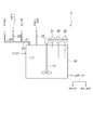
まず、図1に基づき、本発明の一実施形態に係る硫化物沈殿装置1について説明する。
図1において、符号10は反応槽であり、符号11は攪拌機である。反応槽10には、目的金属を含む酸性の処理液が入れられるようになっており、反応槽10に入れられた処理液は攪拌機11により攪拌されるようになっている。反応槽10は、例えばFRP製の槽であるが、塩化ビニル、ポリプロピレン、ゴムライニングを施した鉄等、処理液に腐食されない材質の槽であればよい。また、攪拌機11の攪拌羽は、例えばテフロン(登録商標)製であるがこれ以外の材質のものでもよい。
Next, an embodiment of the present invention will be described with reference to the drawings.
First, based on FIG. 1, the sulfide precipitation apparatus 1 which concerns on one Embodiment of this invention is demonstrated.
In FIG. 1, the code |
また、符号21は硫化剤が流される硫化剤用配管、符号22はアルカリ性水溶液が流されるアルカリ用配管、符号23は混合配管、符号24は洗浄水が流される洗浄水用配管である。硫化剤用配管21およびアルカリ用配管22はともに混合配管23に接続されており、混合配管23において硫化剤とアルカリ性水溶液とが混合されるようになっている。また、混合配管23は反応槽10に接続されており、硫化剤とアルカリ性水溶液とが混合された混合液を反応槽10の内部に滴下できるようになっている。また、混合配管23には、洗浄水用配管24も接続されており、洗浄水用配管24から洗浄水を流すことで混合配管23や反応槽10を洗浄できるようになっている。
硫化剤用配管21、アルカリ用配管22および洗浄水用配管24には、それぞれ流量調整弁が取り付けられており、硫化剤、アルカリ性水溶液および洗浄水の流量を調整できるようになっている。そのため、反応槽10に滴下される混合液中の硫化剤とアルカリ性水溶液の割合を調整できるようになっている。また、混合液と洗浄水の反応槽10への供給/停止を制御できるようになっている。
A flow rate adjusting valve is attached to each of the
硫化剤とアルカリ性水溶液の混合の順番は、アルカリ性水溶液の流れの中に硫化剤を添加してもよいし、硫化剤の流れの中にアルカリ性水溶液を添加してもよいし、硫化剤とアルカリ性水溶液とを同時に混合してもよい。すなわち、硫化剤用配管21とアルカリ用配管22の配置は、混合配管23の上流側にアルカリ用配管22が接続され、下流側に硫化剤用配管21が接続される配置でもよいし(図1参照)、その逆の配置でもよい。また、硫化剤用配管21とアルカリ用配管22と混合配管23をY字管等で接続する構成としてもよい。
The mixing order of the sulfiding agent and the alkaline aqueous solution may be such that the sulfiding agent may be added to the flow of the alkaline aqueous solution, the alkaline aqueous solution may be added to the flow of the sulfiding agent, or the sulfiding agent and the alkaline aqueous solution. May be mixed at the same time. That is, the arrangement of the
なお、硫化剤としては、硫化水素ナトリウム水溶液(NaHS)や硫化ナトリウム水溶液(Na2S)、またはそれらの混合液等の液体の硫化剤を用いることが好ましい。硫化水素ガス等の気体の硫化剤を用いる場合には、毒性のある硫化水素ガスを環境中に放散しないための環集や除害装置などへの設備コストや管理コストがかかるからである。また、アルカリ性水溶液としては、例えば水酸化ナトリウム水溶液(NaOH)が用いられるがこれ以外のアルカリ性水溶液を用いてもよい。ここで、硫化剤として硫化ナトリウム水溶液を用いる場合には、混合液中の硫化ナトリウムは溶解度が低いため、結晶を生じて配管を閉塞する可能性があることから、定期的に洗浄水用配管24から洗浄水を流すことで混合配管23内を洗浄することが好ましい。
As the sulfiding agent, it is preferable to use a liquid sulfiding agent such as a sodium hydrogen sulfide aqueous solution (NaHS), a sodium sulfide aqueous solution (Na 2 S), or a mixture thereof. This is because in the case of using a gaseous sulfiding agent such as hydrogen sulfide gas, there is a facility cost and a management cost for collecting and removing devices for preventing the toxic hydrogen sulfide gas from being released into the environment. Further, as the alkaline aqueous solution, for example, a sodium hydroxide aqueous solution (NaOH) is used, but other alkaline aqueous solutions may be used. Here, when a sodium sulfide aqueous solution is used as the sulfiding agent, sodium sulfide in the mixed solution has low solubility, so that crystals may be formed and the pipe may be blocked. It is preferable to wash the inside of the mixing
さらになお、硫化剤用配管21およびアルカリ用配管22は、例えばテフロン(登録商標)製の配管であるがこれ以外の材質の配管でもよい。また、混合配管23および洗浄水用配管24は、例えば塩化ビニル製の配管であるがこれ以外の材質の配管でもよい。
Furthermore, the
反応槽10には、酸用配管25が接続されており、酸性水溶液を反応槽10の内部に滴下できるようになっている。酸用配管25には流量調整弁が取り付けられており、酸性水溶液の流量を調整でき、反応槽10への供給/停止を制御できるようになっている。
なお、酸性水溶液としては、例えば硫酸(H2SO4)が用いられるが、これ以外の酸性水溶液を用いてもよい。また、酸用配管25は、例えば塩化ビニル製の配管であるが、耐酸性のものであればこれ以外の材質の配管でもよい。
An
For example, sulfuric acid (H 2 SO 4 ) is used as the acidic aqueous solution, but other acidic aqueous solutions may be used. The
反応槽10には、硫化水素ガス濃度計31、pH計32およびORP計33が設けられており、硫化水素ガス濃度計31により反応槽10上部の気相部における硫化水素ガスの濃度を測定でき、pH計32により反応槽10中の処理液のpHを測定でき、ORP計33により反応槽10中の処理液のORP(酸化還元電位)を測定できるようになっている。
The
つぎに、上記硫化物沈殿装置1を用いた硫化物沈殿方法について説明する。
まず、反応槽10に処理液を流入させる。処理液は、例えば廃電池に含まれる有価金属を浸出させた酸性水溶液である。より具体的には、使用済みのニッケル水素電池やリチウムイオン電池等、およびこれらの電池を構成する正極材等の製造工程で生じた不良品(以下、これらをまとめて廃電池という)を焙焼して還元焙焼物とし、この還元焙焼物に硫酸を加えて攪拌し、廃電池に含まれるニッケルやコバルト等の有価金属を浸出させて、浸出残渣と分離して得られたものを処理液とする。また、還元焙焼以外にも、破砕処理した廃電池が投入された液中に亜硫酸ナトリウム等の還元剤と硫酸を加えて攪拌し、廃電池に含まれる有価金属を浸出させて処理液としてもよい。また、処理液は、鉱石に含まれる目的金属を浸出させた酸性溶液でもよい。例えば、ニッケル酸化鉱石や硫化銅鉱物を硫酸や塩酸で浸出して得られたものを処理液とする。
Next, a sulfide precipitation method using the sulfide precipitation apparatus 1 will be described.
First, the processing liquid is caused to flow into the
以下では、廃電池に含まれるニッケルおよびコバルトを浸出させた硫酸水溶液を処理液とし、そのニッケルおよびコバルトを硫化物として沈殿させる場合を例に説明するが、その他の処理液についても同様の方法で目的金属を硫化物として沈殿させることができる。なお、廃電池に含まれるニッケルおよびコバルトを浸出させた硫酸水溶液には、マンガンやアルミニウム等の不純物も含まれる。 In the following, an example is described in which a sulfuric acid aqueous solution in which nickel and cobalt contained in a waste battery are leached is used as a treatment liquid, and the nickel and cobalt are precipitated as sulfides. The target metal can be precipitated as a sulfide. The sulfuric acid aqueous solution in which nickel and cobalt contained in the waste battery are leached also contains impurities such as manganese and aluminum.
つぎに、攪拌機11で処理液を攪拌しながら、アルカリ用配管22からアルカリ性水溶液として水酸化ナトリウム水溶液を供給し、反応槽10の内部に滴下して、処理液のpHを調整する。ここで、処理液は目的金属が硫化物として沈殿し、不純物を分離するのに適したpHに調整される。そのため、目的金属の種類や処理液に含まれる不純物によって、最適なpHに調整される。例えば、ニッケルおよびコバルトを硫化沈殿させる場合には、処理液はpH3に調整される。
Next, while stirring the treatment liquid with the
処理液のpHが調整された後、攪拌機11で処理液を攪拌しながら、硫化剤用配管21から硫化剤として硫化水素ナトリウム水溶液の供給を開始する。そうすると、硫化水素ナトリウム水溶液と、アルカリ用配管22から供給される水酸化ナトリウム水溶液とが混合配管23で混合され、その混合液が反応槽10の内部の処理液に滴下される。
そうすると、以下の反応により、ニッケルが硫化されて硫化ニッケルとして沈殿し、コバルトが硫化されて硫化コバルトとして沈殿する。
(化1)
NiSO4 + NaHS → NiS + NaHSO4
(化2)
CoSO4 + NaHS → CoS + NaHSO4
(化3)
NaHSO4 + NaOH → Na2SO4 + H2O
After the pH of the treatment liquid is adjusted, the supply of the sodium hydrogen sulfide aqueous solution as the sulfiding agent is started from the
Then, by the following reaction, nickel is sulfided and precipitated as nickel sulfide, and cobalt is sulfided and precipitated as cobalt sulfide.
(Chemical formula 1)
NiSO 4 + NaHS → NiS + NaHSO 4
(Chemical formula 2)
CoSO 4 + NaHS → CoS + NaHSO 4
(Chemical formula 3)
NaHSO 4 + NaOH → Na 2 SO 4 + H 2 O
なお、上記硫化反応中は、処理液をpH3付近に維持するように制御する必要がある。この制御は、例えば、硫化水素ナトリウム水溶液と水酸化ナトリウム水溶液の混合割合を、水酸化ナトリウム水溶液をわずかに過剰として、混合液を滴下していくに従って処理液のpHが徐々に上がるようにし、pH計32による測定値がpH3に達したときに、酸用配管25から硫酸を少量滴下し、処理液のpHを若干下げることにより行われる。混合液の滴下を継続すると再び処理液がpH3に達するため、再度硫酸が滴下される。このように、硫酸を間欠的に滴下することにより処理液がpH3付近に維持される。この様な方法で制御を行う理由は、硫化反応の終点では下記化4の反応によって処理液のpHが急速に上昇することから、処理液のpHを下げる硫酸の滴下を主体として制御する方が、硫化反応の終点における処理液のpHの急速な上昇にも対応しやすいからである。
During the sulfidation reaction, it is necessary to control so that the treatment liquid is maintained at around pH 3. This control is performed, for example, by adjusting the mixing ratio of the aqueous sodium hydrogen sulfide solution and the aqueous sodium hydroxide solution so that the aqueous sodium hydroxide solution is slightly excessive, and the pH of the treatment liquid gradually increases as the mixed liquid is dropped. When the value measured by the total 32 reaches pH 3, a small amount of sulfuric acid is dropped from the
前述のごとく、従来のように処理液に硫化水素ナトリウム水溶液と水酸化ナトリウム水溶液とを別々に滴下した場合には、ニッケルおよびコバルトが処理液に残存している場合においても、以下の反応が起こり、硫化水素が発生する。
(化4)
H2SO4 + NaHS → H2S + NaHSO4
As described above, when sodium hydrogen sulfide aqueous solution and sodium hydroxide aqueous solution are dropped separately into the treatment liquid as in the past, the following reaction occurs even when nickel and cobalt remain in the treatment liquid. Hydrogen sulfide is generated.
(Chemical formula 4)
H 2 SO 4 + NaHS → H 2 S + NaHSO 4
しかし、本願発明者は、硫化水素ナトリウム水溶液と水酸化ナトリウム水溶液とを混合した混合液を処理液に滴下することにより、ニッケルおよびコバルトが処理液に残存している状態において硫化水素ガスの発生が抑制されることを見出した。
そのため、本発明を適用することにより、硫化水素ガスの発生が抑制されるので、毒性のある硫化水素ガスの処理負荷を軽減できる。また、余分な硫化水素ガスが発生せず、硫化剤やアルカリ性溶液が効率的に硫化物の生成に使用されるため、硫化剤やアルカリ性溶液の使用量を少なくできコストを低減できる。
However, the inventor of the present application drops hydrogen sulfide gas in a state in which nickel and cobalt remain in the treatment liquid by dropping a mixed liquid of a sodium hydrogen sulfide aqueous solution and a sodium hydroxide aqueous solution into the treatment liquid. It was found to be suppressed.
Therefore, by applying the present invention, generation of hydrogen sulfide gas is suppressed, so that the processing load of toxic hydrogen sulfide gas can be reduced. Further, no excessive hydrogen sulfide gas is generated, and the sulfiding agent and the alkaline solution are efficiently used for the production of sulfides. Therefore, the amount of the sulfiding agent and the alkaline solution used can be reduced, and the cost can be reduced.
硫化水素ガスの発生が抑制されるメカニズムは以下のとおりであると考えられる。
すなわち、硫化水素ナトリウム水溶液と水酸化ナトリウム水溶液とを別々に滴下すると、処理液中の硫化水素ナトリウム水溶液が滴下された部分は局所的に硫化水素ナトリウム水溶液の濃度が高くなり、化1および化2の硫化反応により局所的にニッケルおよびコバルトの濃度が低下する。そのため、化4の反応も生じて硫化水素が発生すると考えられる。また、水酸化ナトリウム水溶液についても同様に、化3の反応のみならず、不純物であるマンガンとの間で以下の反応が生じると考えられる。
(化5)
MnSO4 + 2NaOH → Mn(OH)2 + Na2SO4
The mechanism by which the generation of hydrogen sulfide gas is suppressed is considered as follows.
That is, when the sodium hydrogen sulfide aqueous solution and the sodium hydroxide aqueous solution are dropped separately, the concentration of the sodium hydrogen sulfide aqueous solution locally increases in the portion of the treatment liquid where the sodium hydrogen sulfide aqueous solution is dropped. The concentration of nickel and cobalt locally decreases due to the sulfurization reaction. Therefore, it is considered that the reaction of Chemical Formula 4 also occurs and hydrogen sulfide is generated. Similarly, with respect to an aqueous sodium hydroxide solution, it is considered that not only the reaction of Chemical Formula 3 but also the following reaction occurs with manganese as an impurity.
(Chemical formula 5)
MnSO 4 + 2NaOH → Mn (OH) 2 + Na 2 SO 4
一方、硫化水素ナトリウム水溶液と水酸化ナトリウム水溶液とを混合して滴下すれば、化4および化5の反応を抑制し、化1、化2および化3の反応を効率的に進行させることが可能となり、その結果、硫化水素ガスの発生が抑制されると考えられる。 On the other hand, if a sodium hydrogen sulfide aqueous solution and a sodium hydroxide aqueous solution are mixed and added dropwise, it is possible to suppress the reactions of Chemical Formula 4 and Chemical Formula 5 and to efficiently advance the reactions of Chemical Formula 1, Chemical Formula 2 and Chemical Formula 3 As a result, it is considered that generation of hydrogen sulfide gas is suppressed.
つぎに、処理液中のニッケルおよびコバルトが硫化物として沈殿し尽くすと、上記化4の反応により、硫化水素ガスが発生する。
そこで、硫化水素ガス濃度計31により発生する硫化水素ガスの濃度を測定し、その濃度が予め定めておいた閾値を超えたときを硫化反応の終点と判定する。硫化水素ガスの濃度を測定することにより、単位時間あたりの硫化水素ガスの発生量を測定することができ、化4の反応が始まったことが検知されるので、硫化反応の終点を判定できるのである。
硫化反応の終点と判定すると硫化処理を終了させる。具体的には、硫化水素ナトリウム水溶液および水酸化ナトリウム水溶液の反応槽10への供給を停止し、反応槽10中の処理液を排出する。
Next, when nickel and cobalt in the treatment liquid are completely precipitated as sulfides, hydrogen sulfide gas is generated by the reaction of the above chemical formula 4.
Therefore, the concentration of hydrogen sulfide gas generated by the hydrogen sulfide
If it is determined that the end point of the sulfurization reaction, the sulfurization process is terminated. Specifically, the supply of the sodium hydrogen sulfide aqueous solution and the sodium hydroxide aqueous solution to the
本発明を適用することにより、ニッケルおよびコバルトが処理液に残存している状態において硫化水素ガスの発生が抑制され、ニッケルおよびコバルトが硫化物として沈殿し尽くすと硫化水素ガスが発生する。すなわち、硫化反応の終点において硫化水素ガスの濃度が急激に高くなるので、硫化水素ガスの濃度を測定することによって硫化反応の終点を容易に判定することができる。
また、硫化反応の終点で処理を終了させることにより、発生する硫化水素ガスの量を抑制でき、毒性のある硫化水素ガスの処理負荷を軽減できる。さらに、硫化反応の終点で処理を終了させることにより硫化剤やアルカリ性溶液を目的金属の硫化に必要な量だけに抑制でき、コストを低減できる。
By applying the present invention, generation of hydrogen sulfide gas is suppressed in a state where nickel and cobalt remain in the processing liquid, and hydrogen sulfide gas is generated when nickel and cobalt are precipitated as sulfides. That is, since the concentration of the hydrogen sulfide gas rapidly increases at the end point of the sulfurization reaction, the end point of the sulfurization reaction can be easily determined by measuring the concentration of the hydrogen sulfide gas.
Moreover, by terminating the treatment at the end point of the sulfurization reaction, the amount of generated hydrogen sulfide gas can be suppressed, and the treatment load of toxic hydrogen sulfide gas can be reduced. Furthermore, by terminating the treatment at the end point of the sulfidation reaction, the sulfiding agent and the alkaline solution can be suppressed to only the amount necessary for sulfiding the target metal, and the cost can be reduced.
最後に、反応槽10から排出された処理液をフィルタープレス等で固液分離し、硫化物と硫化後液とを分離する。有価金属であるニッケルおよびコバルトは硫化物として沈殿し、不純物であるマンガンやアルミニウム等は硫化後液に溶解されているので、固液分離により有価金属と不純物とを分離でき、廃電池から高純度の有価金属を回収することができる。また、鉱石に含まれる目的金属を浸出させた酸性溶液を処理液とした場合には、鉱石に含まれる目的金属を不純物と分離できるので、高純度の目的金属を採取することができる。
Finally, the treatment liquid discharged from the
なお、上記工程の内、処理液に混合液を滴下する前に、アルカリ性水溶液を滴下してpH調整する工程においては、化5の反応によりアルカリ塩が生成される。このアルカリ塩は処理液のpHが低い場合にはすぐに再溶解するが、処理液のpHが上がってくるとすぐに再溶解せず、固体として所定時間処理液内に滞留する。そして、このpH調整の直後に混合液を滴下し始めると、個体として滞留するアルカリ塩の周囲に不溶性の硫化物が生成されるため、アルカリ塩が再溶解できなくなる。そうすると、硫化物に不純物金属が混入することになる。これを防止するためは、混合液の滴下開始前にアルカリ塩が再溶解するための時間を設ければよい。すなわち、処理液のpHが調整された後、一度アルカリ性水溶液の供給を停止し、再溶解時間を待った後に、混合液の滴下を開始すればよい。このアルカリ塩の再溶解時間は、処理液に含まれる不純物の種類や量を元に選択される。このようにすることで、得られる硫化物の純度を高めることができる。 In the step of adjusting the pH by dropping an alkaline aqueous solution before dropping the mixed solution into the treatment solution, an alkali salt is generated by the reaction of Chemical Formula 5 among the above steps. This alkali salt is redissolved immediately when the pH of the treatment liquid is low, but does not immediately re-dissolve when the pH of the treatment liquid rises, and remains in the treatment liquid as a solid for a predetermined time. If the mixed solution starts dripping immediately after the pH adjustment, an insoluble sulfide is generated around the alkali salt that remains as a solid, so that the alkali salt cannot be redissolved. If it does so, an impurity metal will mix in sulfide. In order to prevent this, it is only necessary to provide time for the alkali salt to redissolve before the start of dropping of the mixed solution. That is, after the pH of the treatment liquid is adjusted, the supply of the alkaline aqueous solution is once stopped, and after waiting for the re-dissolution time, the dropping of the mixed liquid may be started. The alkali salt re-dissolution time is selected based on the type and amount of impurities contained in the treatment liquid. By doing in this way, the purity of the obtained sulfide can be increased.
また、上記の硫化処理の工程において、硫化物のスラリー濃度が高いと、若干量の不純物金属も共沈する。これを防止するためには、反応槽10に流入させる処理液を予め希釈しておくことにより、硫化物のスラリー濃度を下げればよい。この処理液の希釈度は、処理液に含まれる不純物の種類や量を元に選択される。このようにすることで、共沈効果を小さくでき、得られる硫化物の純度を高めることができる。
Further, in the above sulfidation process, if the sulfide slurry concentration is high, some amount of impurity metal is co-precipitated. In order to prevent this, the concentration of the sulfide slurry may be lowered by diluting the treatment liquid flowing into the
つぎに、実施例について説明する。
以下の実施例および比較例では、ともに廃電池に含まれるニッケルおよびコバルトを浸出させた硫酸水溶液を処理液とした。具体的には、使用済みのニッケル水素電池を焙焼して還元焙焼物とし、この還元焙焼物(55kg)にpH1となるように硫酸を加え、スラリー濃度が110g/Lとなるように希釈し、80℃に加熱して6時間攪拌し、ニッケル水素電池に含まれるニッケルおよびコバルトを浸出させた。つぎに、硫酸ナトリウムを添加して、希土類元素などを硫酸複塩の形で分離して、処理液を得た。処理液には、ニッケルやコバルト等の有価金属のほかに、マンガンやアルミニウム等の不純物も含有されていた。
Next, examples will be described.
In the following examples and comparative examples, a sulfuric acid aqueous solution in which nickel and cobalt contained in a waste battery were leached was used as a treatment liquid. Specifically, a used nickel metal hydride battery is roasted to obtain a reduced roasted product, and sulfuric acid is added to this reduced roasted product (55 kg) so that the pH is 1, and diluted to a slurry concentration of 110 g / L. The mixture was heated to 80 ° C. and stirred for 6 hours to leach out nickel and cobalt contained in the nickel metal hydride battery. Next, sodium sulfate was added to separate rare earth elements and the like in the form of a sulfate double salt to obtain a treatment liquid. The treatment liquid contained impurities such as manganese and aluminum in addition to valuable metals such as nickel and cobalt.
(実施例)
まず、前述の硫化物沈殿装置1の反応槽10に処理液を流入させた。ここで、反応槽10は直径1m、高さ1.3mの円筒形であり容量750リットルである。
つぎに、アルカリ用配管22から水酸化ナトリウム水溶液を供給し、反応槽10の内部に滴下して、処理液をpH3に調整した。
(Example)
First, the treatment liquid was caused to flow into the
Next, an aqueous sodium hydroxide solution was supplied from the alkali pipe 22 and dropped into the
つぎに、硫化剤用配管21から硫化剤として濃度25%の硫化水素ナトリウム水溶液を供給し、アルカリ用配管22からアルカリ性水溶液として濃度25%の水酸化ナトリウム水溶液を供給し、混合配管23で硫化水素ナトリウム水溶液と水酸化ナトリウム水溶液を混合して、その混合液を反応槽10の内部の処理液に滴下した。ここで、硫化水素ナトリウム水溶液と水酸化ナトリウム水溶液との混合割合がほぼ等モル量となるように、それぞれの流量を調整した。
また、それと同時に、攪拌機11の攪拌羽の回転速度を毎分200回転として、処理液を攪拌した。
Next, a sodium hydrogen sulfide aqueous solution having a concentration of 25% is supplied from the
At the same time, the processing liquid was stirred at a rotation speed of the stirring blade of the
なお、硫化反応中は、硫化水素ナトリウム水溶液と水酸化ナトリウム水溶液の混合割合を、水酸化ナトリウム水溶液をわずかに過剰として、混合液を滴下していくに従って処理液のpHが徐々に上がるようにし、pH計32による測定値がpH3に達したときに、酸用配管25から硫酸を少量滴下し、処理液のpHを若干下げることにより行った。
During the sulfidation reaction, the mixing ratio of the sodium hydrogen sulfide aqueous solution and the sodium hydroxide aqueous solution is set so that the sodium hydroxide aqueous solution is slightly excessive, and the pH of the treatment liquid gradually increases as the mixture is dropped. When the value measured by the
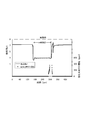
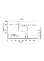
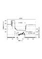
硫化水素ガス濃度計31、pH計32およびORP計33により、反応槽10上部の気相部における硫化水素ガスの濃度、処理液のpHおよびORPをモニタリングした結果、図2および図3に示すグラフが得られた。なお、pH計32およびORP計33は、電極の乾燥防止のため、反応槽10に処理液を満たした後に反応槽10に設置し、硫化反応の終了後に反応槽10から取り外した。それ以外の場合、すなわち、反応槽10に処理液が満たされる前と、硫化反応の終了後は、pH計32およびORP計33は乾燥防止用の水に浸けた。そのため、硫化反応の前後におけるpH計32およびORP計33の測定値は、処理液の測定値ではなく乾燥防止用の水の測定値である。図2および図3において、pH計32およびORP計33を反応槽10に設置しているのは、「pH計設置」または「ORP計設置」と記載した領域である。
As a result of monitoring the concentration of hydrogen sulfide gas, the pH of the treatment liquid, and the ORP in the gas phase portion of the upper part of the
図2に示すように、硫化反応中の硫化水素ガス濃度は1ppm未満であり、硫化水素ガスの発生が抑制されることが確認された。また、混合液の滴下開始後110分を経過した頃から急激に硫化水素ガス濃度が上昇した。 As shown in FIG. 2, the hydrogen sulfide gas concentration during the sulfidation reaction was less than 1 ppm, and it was confirmed that the generation of hydrogen sulfide gas was suppressed. Further, the hydrogen sulfide gas concentration suddenly increased from about 110 minutes after the start of dropping of the mixed solution.
ところで、硫化反応の終点は、硫酸滴下の頻度により判断できる。より詳細には、図2に示すように、硫化反応中の処理液のpHは鋸刃状に変化する。これは、混合液を滴下していくに従って処理液のpHが徐々に上がり、硫酸を滴下したときに処理液のpHが下がるからである。すなわち、鋸刃状のpH変動の周期により硫酸滴下の頻度が分かる。硫化反応の終点に近づくと、混合液の滴下により処理液のpHが上がりやすくなるため、処理液のpHを下げる硫酸の滴下頻度が高くなる。そのため、硫酸滴下の頻度が所定の頻度を超えた時を硫化反応の終点と判断できるのである。 By the way, the end point of the sulfurization reaction can be judged by the frequency of sulfuric acid dropping. More specifically, as shown in FIG. 2, the pH of the treatment liquid during the sulfidation reaction changes in a sawtooth shape. This is because the pH of the treatment liquid gradually increases as the mixed solution is dropped, and the pH of the treatment liquid decreases when sulfuric acid is dropped. That is, the frequency of sulfuric acid dripping can be found from the sawtooth-like pH fluctuation cycle. When the end point of the sulfidation reaction is approached, the pH of the treatment liquid is likely to increase due to the dropping of the mixed liquid, so that the dropping frequency of sulfuric acid that lowers the pH of the treatment liquid increases. Therefore, when the frequency of sulfuric acid dripping exceeds a predetermined frequency, the end point of the sulfurization reaction can be determined.
図2より、硫化水素ガス濃度が急激に上昇しているときに硫酸滴下の頻度が高くなっている。すなわち、硫化反応の終点において硫化水素ガスが発生していることが分かる。これより、本実施例において、硫化反応中は硫化水素ガスの発生が抑制され、硫化反応が終点に達したときに硫化水素ガスの発生することが確認された。 From FIG. 2, the frequency of sulfuric acid dripping is high when the hydrogen sulfide gas concentration is rapidly increasing. That is, it can be seen that hydrogen sulfide gas is generated at the end of the sulfurization reaction. Thus, in this example, it was confirmed that the generation of hydrogen sulfide gas was suppressed during the sulfidation reaction, and hydrogen sulfide gas was generated when the sulfidation reaction reached the end point.
図3に示すように、ORPは混合液を滴下していくに従って徐々に低下し、ORPが-300mV(Ag/AgCl電極)付近に達すると急激に低下した。これは、処理液中のニッケルおよびコバルトが硫化物として沈殿し尽くすと、上記化4の反応により硫化水素ガスが発生し、この硫化水素ガスが処理液を還元するためである。そのため、硫化水素ガスが発生し、ORPが急激に低下する時点から、硫化反応が終点に達した時点を判断することができる。 As shown in FIG. 3, the ORP gradually decreased as the mixed solution was dropped, and decreased rapidly when the ORP reached around -300 mV (Ag / AgCl electrode). This is because when nickel and cobalt in the treatment liquid are completely precipitated as sulfides, hydrogen sulfide gas is generated by the reaction of Chemical Formula 4, and this hydrogen sulfide gas reduces the treatment liquid. For this reason, it is possible to determine when the sulfurization reaction reaches the end point from the time when hydrogen sulfide gas is generated and the ORP rapidly decreases.
硫化反応の終了後、反応槽10から排出された処理液をフィルタープレスで固液分離し、硫化物と硫化後液とを分離した。ここで、硫化反応の終点は処理液がpH3を超えた時点から判断した。より詳細には、化4の効果により処理液のpHが急速に上昇し、硫酸を滴下してもpHが十分に下がらない状態となったときを硫化反応の終点と判断した。
After completion of the sulfidation reaction, the treatment liquid discharged from the
得られた硫化物をICP発光分析装置で分析すると、マンガン品位は0.14%と十分低いことが分かった。また、硫化反応前の処理液と硫化物の量およびマンガン品位からニッケルおよびコバルトの回収率を計算すると、99%以上であり充分に回収できたことが確認された。 When the obtained sulfide was analyzed with an ICP emission spectrometer, the manganese quality was found to be sufficiently low at 0.14%. Further, when the recovery rate of nickel and cobalt was calculated from the amount of the treatment solution and sulfide before the sulfidation reaction and the manganese quality, it was confirmed that the recovery rate was 99% or more and was sufficiently recovered.
(比較例)
硫化剤としての硫化水素ナトリウム水溶液とアルカリ性水溶液としての水酸化ナトリウム水溶液を別々に処理液に滴下した以外は、実施例と同様に処理した。
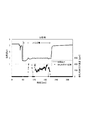
硫化水素ガス濃度計31、pH計32およびORP計33により、反応槽10上部の気相部における硫化水素ガスの濃度、処理液のpHおよびORPをモニタリングした結果、図4および図5に示すグラフが得られた。図4および図5においても、pH計32およびORP計33を反応槽10に設置しているのは、「pH計設置」または「ORP計設置」と記載した領域である。
(Comparative example)
The treatment was performed in the same manner as in the example except that a sodium hydrogen sulfide aqueous solution as a sulfiding agent and a sodium hydroxide aqueous solution as an alkaline aqueous solution were separately dropped into the treatment liquid.
As a result of monitoring the concentration of hydrogen sulfide gas, the pH of the treatment liquid, and the ORP in the gas phase portion of the upper part of the
図4および図5に示すように、ORPの変化、pHの変化および硫酸供給頻度は、実施例と大きな違いは無かった。
また、得られた硫化物のマンガン品位は0.12%であり、ニッケルおよびコバルトの回収率は99%以上であり、実施例と大きな違いは無かった。
As shown in FIGS. 4 and 5, the change in ORP, the change in pH, and the frequency of sulfuric acid supply were not significantly different from those in the Examples.
Further, the manganese quality of the obtained sulfide was 0.12%, and the recovery rate of nickel and cobalt was 99% or more, which was not significantly different from the examples.
しかし、硫化水素ガス濃度は、硫化水素ナトリウム水溶液の滴下開始後速やかに上昇し、硫化反応中であっても200〜400ppmであることが確認された。
以上より、本発明を適用することにより、硫化水素ガスの発生を抑制でき、毒性のある硫化水素ガスの処理負荷を軽減でき、硫化剤やアルカリ性溶液の使用量を少なくできることが確認された。
However, the hydrogen sulfide gas concentration rapidly increased after the start of dropping of the aqueous sodium hydrogen sulfide solution, and it was confirmed that it was 200 to 400 ppm even during the sulfurization reaction.
From the above, it was confirmed that by applying the present invention, the generation of hydrogen sulfide gas can be suppressed, the processing load of toxic hydrogen sulfide gas can be reduced, and the amount of sulfiding agent and alkaline solution used can be reduced.
1 硫化物沈殿装置
10 反応槽
11 攪拌機
21 硫化剤用配管
22 アルカリ用配管
23 混合配管
24 洗浄水用配管
25 酸用配管
31 硫化水素ガス濃度計
32 pH計
33 ORP計
DESCRIPTION OF SYMBOLS 1
Claims (5)
前記硫化剤と前記アルカリ性水溶液とを混合し、
該混合液を前記処理液に添加する
ことを特徴とする金属の硫化物沈殿方法。 It was added and sulfurizing agent and an alkaline aqueous solution composed of sodium hydrosulfide aqueous treating solution of sulfuric acid or hydrochloric acid (NaHS) containing the desired metal, metal sulfides precipitating the said purpose metal as a sulfide while maintaining pH A precipitation method,
Mixing the sulfiding agent and the alkaline aqueous solution,
A metal sulfide precipitation method comprising adding the mixed solution to the treatment solution.
該単位時間あたりの発生量が閾値を超えたときに処理を終了させる
ことを特徴とする請求項1記載の金属の硫化物沈殿方法。 Measure the amount of hydrogen sulfide gas generated per unit time generated by adding the mixed solution to the treatment solution,
2. The metal sulfide precipitation method according to claim 1, wherein the treatment is terminated when the generation amount per unit time exceeds a threshold value.
ことを特徴とする請求項1または2記載の金属の硫化物沈殿方法。 3. The metal sulfide precipitation method according to claim 1, wherein the treatment liquid is obtained by leaching a valuable metal contained in a waste battery in an acidic aqueous solution.
ことを特徴とする請求項1または2記載の金属の硫化物沈殿方法。 3. The metal sulfide precipitation method according to claim 1, wherein the treatment liquid is obtained by leaching a target metal contained in an ore into an acidic aqueous solution.
硫化水素ナトリウム水溶液(NaHS)からなる硫化剤が流される硫化剤用配管と、
アルカリ性水溶液が流されるアルカリ用配管と、
前記硫化剤用配管と前記アルカリ用配管とが接続され、前記硫化剤と前記アルカリ性水溶液とを混合して、該混合液を前記反応槽に滴下する混合配管と、を備える
ことを特徴とする金属の硫化物沈殿装置。 A reaction vessel in which a sulfuric acid-acid or hydrochloric acid-acid treatment liquid containing the target metal is placed;
A pipe for sulfiding agent through which a sulfiding agent composed of a sodium hydrogen sulfide aqueous solution (NaHS) flows
An alkali pipe through which an alkaline aqueous solution flows;
A metal comprising: a pipe for connecting the sulfiding agent pipe and the alkali pipe, mixing the sulfiding agent and the alkaline aqueous solution, and dropping the mixed liquid into the reaction vessel. Sulfide precipitation equipment.
Priority Applications (1)
| Application Number | Priority Date | Filing Date | Title |
|---|---|---|---|
| JP2011195557A JP5716614B2 (en) | 2011-09-08 | 2011-09-08 | Metal sulfide precipitation method |
Applications Claiming Priority (1)
| Application Number | Priority Date | Filing Date | Title |
|---|---|---|---|
| JP2011195557A JP5716614B2 (en) | 2011-09-08 | 2011-09-08 | Metal sulfide precipitation method |
Publications (2)
| Publication Number | Publication Date |
|---|---|
| JP2013057097A JP2013057097A (en) | 2013-03-28 |
| JP5716614B2 true JP5716614B2 (en) | 2015-05-13 |
Family
ID=48133202
Family Applications (1)
| Application Number | Title | Priority Date | Filing Date |
|---|---|---|---|
| JP2011195557A Active JP5716614B2 (en) | 2011-09-08 | 2011-09-08 | Metal sulfide precipitation method |
Country Status (1)
| Country | Link |
|---|---|
| JP (1) | JP5716614B2 (en) |
Families Citing this family (11)
| Publication number | Priority date | Publication date | Assignee | Title |
|---|---|---|---|---|
| JP2015114302A (en) * | 2013-12-16 | 2015-06-22 | 住友金属鉱山株式会社 | Mounting structure of oxidation-reduction potentiometer in reaction tank |
| JP6201911B2 (en) * | 2014-06-26 | 2017-09-27 | 住友金属鉱山株式会社 | Method for controlling metal sulfide formation reaction |
| CN107046154B (en) * | 2017-04-18 | 2022-07-08 | 中科过程(北京)科技有限公司 | Method for enhanced reduction leaching of waste ternary lithium battery |
| CN113125432A (en) * | 2019-12-30 | 2021-07-16 | 财团法人工业技术研究院 | Method for detecting sulfide content by metal ion solution |
| JP2023516663A (en) * | 2020-03-02 | 2023-04-20 | エルアイ - サイクル コーポレイション | Disposal method of lithium iron phosphate battery |
| JP7243749B2 (en) * | 2021-02-17 | 2023-03-22 | 三菱マテリアル株式会社 | Valuable metal recovery method and recovery device |
| CN112960829B (en) * | 2021-02-20 | 2022-08-23 | 成都明天高新产业有限责任公司 | Process for treating copper-containing wastewater generated in production of printed circuit boards |
| KR20250023495A (en) * | 2022-06-10 | 2025-02-18 | 유미코아 | Sulfidification of solid metal feeds containing Ni and/or Co |
| US20250313491A1 (en) * | 2022-06-10 | 2025-10-09 | Umicore | Process for metal sulphidation |
| CN116240391A (en) * | 2022-12-28 | 2023-06-09 | 甘肃厂坝有色金属有限责任公司 | Wet zinc smelting waste acid treatment process |
| CN117209101A (en) * | 2023-11-07 | 2023-12-12 | 河南睿嘉环保科技有限责任公司 | Industrial waste water purifying, detecting and discharging device |
Family Cites Families (2)
| Publication number | Priority date | Publication date | Assignee | Title |
|---|---|---|---|---|
| JP4457864B2 (en) * | 2004-11-24 | 2010-04-28 | 住友金属鉱山株式会社 | Method for recovering nickel and / or cobalt sulfide |
| JP5012970B2 (en) * | 2010-07-21 | 2012-08-29 | 住友金属鉱山株式会社 | Method for separating nickel and cobalt from active materials contained in used nickel metal hydride batteries |
-
2011
- 2011-09-08 JP JP2011195557A patent/JP5716614B2/en active Active
Also Published As
| Publication number | Publication date |
|---|---|
| JP2013057097A (en) | 2013-03-28 |
Similar Documents
| Publication | Publication Date | Title |
|---|---|---|
| JP5716614B2 (en) | Metal sulfide precipitation method | |
| JP4888580B2 (en) | Liquid storage device and pressure control method thereof | |
| JP5904459B2 (en) | Manufacturing method of high purity nickel sulfate | |
| US8716177B2 (en) | Production process of sulfide containing nickel and cobalt | |
| JP5716636B2 (en) | Metal sulfide precipitation method | |
| JP6135609B2 (en) | How to blow gas into the autoclave | |
| JP6365838B2 (en) | Cobalt nickel leaching method | |
| TW202244280A (en) | Precipitation of metals | |
| CN107429317A (en) | Manufacture method, the wet type smelting process of nickel oxide ore of the mixed sulfides of nickel and cobalt | |
| JP6540548B2 (en) | Method for removing copper ions from aqueous solution of nickel chloride, copper ion removal treatment apparatus | |
| JP5125543B2 (en) | Method for producing sulfide containing nickel and cobalt | |
| JP6953988B2 (en) | How to remove sulfide | |
| JP6747620B2 (en) | Ni/Co sulfide manufacturing method and iron quality stabilizing system | |
| AU2017341012A1 (en) | Hydrometallurgical method for refining nickel oxide ore | |
| JP6610368B2 (en) | Method for removing impurities from aqueous nickel chloride solution | |
| JP6256491B2 (en) | Scandium recovery method | |
| KR102942700B1 (en) | Method for recovering manganese contained in waste batteries and recovery equipment | |
| JP5673471B2 (en) | Method for removing copper ions in aqueous nickel chloride solution and method for producing electronickel | |
| JP6724351B2 (en) | How to remove sulfiding agent | |
| JP6201911B2 (en) | Method for controlling metal sulfide formation reaction | |
| JP6981206B2 (en) | Nickel sulfate aqueous solution dezincification system and its method | |
| JP7355186B1 (en) | Particle size control method for nickel-cobalt mixed sulfide | |
| KR102942701B1 (en) | Method for recovering manganese contained in waste batteries and recovery equipment | |
| JP7585921B2 (en) | Hydrometallurgical process for nickel oxide ore | |
| JP2019181349A (en) | Sulfurizing agent removal method, and wet-type method of refining nickel oxide ore |
Legal Events
| Date | Code | Title | Description |
|---|---|---|---|
| A621 | Written request for application examination |
Free format text: JAPANESE INTERMEDIATE CODE: A621 Effective date: 20130919 |
|
| A131 | Notification of reasons for refusal |
Free format text: JAPANESE INTERMEDIATE CODE: A131 Effective date: 20140902 |
|
| A521 | Written amendment |
Free format text: JAPANESE INTERMEDIATE CODE: A523 Effective date: 20141001 |
|
| TRDD | Decision of grant or rejection written | ||
| A01 | Written decision to grant a patent or to grant a registration (utility model) |
Free format text: JAPANESE INTERMEDIATE CODE: A01 Effective date: 20150217 |
|
| A61 | First payment of annual fees (during grant procedure) |
Free format text: JAPANESE INTERMEDIATE CODE: A61 Effective date: 20150302 |
|
| R150 | Certificate of patent or registration of utility model |
Ref document number: 5716614 Country of ref document: JP Free format text: JAPANESE INTERMEDIATE CODE: R150 |