JP5723073B2 - Centrifugal cutoff clutch - Google Patents
Centrifugal cutoff clutch Download PDFInfo
- Publication number
- JP5723073B2 JP5723073B2 JP2014530010A JP2014530010A JP5723073B2 JP 5723073 B2 JP5723073 B2 JP 5723073B2 JP 2014530010 A JP2014530010 A JP 2014530010A JP 2014530010 A JP2014530010 A JP 2014530010A JP 5723073 B2 JP5723073 B2 JP 5723073B2
- Authority
- JP
- Japan
- Prior art keywords
- rotor assembly
- rotor
- motor
- centrifugal
- clutch
- Prior art date
- Legal status (The legal status is an assumption and is not a legal conclusion. Google has not performed a legal analysis and makes no representation as to the accuracy of the status listed.)
- Active
Links
Images


Classifications
-
- F—MECHANICAL ENGINEERING; LIGHTING; HEATING; WEAPONS; BLASTING
- F16—ENGINEERING ELEMENTS AND UNITS; GENERAL MEASURES FOR PRODUCING AND MAINTAINING EFFECTIVE FUNCTIONING OF MACHINES OR INSTALLATIONS; THERMAL INSULATION IN GENERAL
- F16D—COUPLINGS FOR TRANSMITTING ROTATION; CLUTCHES; BRAKES
- F16D43/00—Automatic clutches
- F16D43/02—Automatic clutches actuated entirely mechanically
- F16D43/04—Automatic clutches actuated entirely mechanically controlled by angular speed
- F16D43/14—Automatic clutches actuated entirely mechanically controlled by angular speed with centrifugal masses actuating the clutching members directly in a direction which has at least a radial component; with centrifugal masses themselves being the clutching members
- F16D43/18—Automatic clutches actuated entirely mechanically controlled by angular speed with centrifugal masses actuating the clutching members directly in a direction which has at least a radial component; with centrifugal masses themselves being the clutching members with friction clutching members
-
- B—PERFORMING OPERATIONS; TRANSPORTING
- B64—AIRCRAFT; AVIATION; COSMONAUTICS
- B64C—AEROPLANES; HELICOPTERS
- B64C11/00—Propellers, e.g. of ducted type; Features common to propellers and rotors for rotorcraft
- B64C11/02—Hub construction
- B64C11/04—Blade mountings
-
- B—PERFORMING OPERATIONS; TRANSPORTING
- B64—AIRCRAFT; AVIATION; COSMONAUTICS
- B64C—AEROPLANES; HELICOPTERS
- B64C27/00—Rotorcraft; Rotors peculiar thereto
- B64C27/32—Rotors
- B64C27/46—Blades
- B64C27/473—Constructional features
- B64C27/48—Root attachment to rotor head
-
- B—PERFORMING OPERATIONS; TRANSPORTING
- B64—AIRCRAFT; AVIATION; COSMONAUTICS
- B64C—AEROPLANES; HELICOPTERS
- B64C29/00—Aircraft capable of landing or taking-off vertically, e.g. vertical take-off and landing [VTOL] aircraft
- B64C29/0008—Aircraft capable of landing or taking-off vertically, e.g. vertical take-off and landing [VTOL] aircraft having its flight directional axis horizontal when grounded
- B64C29/0016—Aircraft capable of landing or taking-off vertically, e.g. vertical take-off and landing [VTOL] aircraft having its flight directional axis horizontal when grounded the lift during taking-off being created by free or ducted propellers or by blowers
- B64C29/0025—Aircraft capable of landing or taking-off vertically, e.g. vertical take-off and landing [VTOL] aircraft having its flight directional axis horizontal when grounded the lift during taking-off being created by free or ducted propellers or by blowers the propellers being fixed relative to the fuselage
-
- F—MECHANICAL ENGINEERING; LIGHTING; HEATING; WEAPONS; BLASTING
- F16—ENGINEERING ELEMENTS AND UNITS; GENERAL MEASURES FOR PRODUCING AND MAINTAINING EFFECTIVE FUNCTIONING OF MACHINES OR INSTALLATIONS; THERMAL INSULATION IN GENERAL
- F16D—COUPLINGS FOR TRANSMITTING ROTATION; CLUTCHES; BRAKES
- F16D59/00—Self-acting brakes, e.g. coming into operation at a predetermined speed
- F16D59/02—Self-acting brakes, e.g. coming into operation at a predetermined speed spring-loaded and adapted to be released by mechanical, fluid, or electromagnetic means
-
- F—MECHANICAL ENGINEERING; LIGHTING; HEATING; WEAPONS; BLASTING
- F16—ENGINEERING ELEMENTS AND UNITS; GENERAL MEASURES FOR PRODUCING AND MAINTAINING EFFECTIVE FUNCTIONING OF MACHINES OR INSTALLATIONS; THERMAL INSULATION IN GENERAL
- F16D—COUPLINGS FOR TRANSMITTING ROTATION; CLUTCHES; BRAKES
- F16D43/00—Automatic clutches
- F16D43/02—Automatic clutches actuated entirely mechanically
- F16D43/04—Automatic clutches actuated entirely mechanically controlled by angular speed
- F16D43/14—Automatic clutches actuated entirely mechanically controlled by angular speed with centrifugal masses actuating the clutching members directly in a direction which has at least a radial component; with centrifugal masses themselves being the clutching members
- F16D2043/145—Automatic clutches actuated entirely mechanically controlled by angular speed with centrifugal masses actuating the clutching members directly in a direction which has at least a radial component; with centrifugal masses themselves being the clutching members the centrifugal masses being pivoting
Landscapes
- Engineering & Computer Science (AREA)
- General Engineering & Computer Science (AREA)
- Aviation & Aerospace Engineering (AREA)
- Mechanical Engineering (AREA)
- Physics & Mathematics (AREA)
- Electromagnetism (AREA)
- One-Way And Automatic Clutches, And Combinations Of Different Clutches (AREA)
- Mechanical Operated Clutches (AREA)
- Braking Arrangements (AREA)
Description
この開示は、ローターが閾速度よりも低速で回転することを機械的に阻止するが、ローターが閾速度以上で自由に回転することを可能にする機械的機構を記述する。 This disclosure describes a mechanical mechanism that mechanically prevents the rotor from rotating below the threshold speed, but allows the rotor to rotate freely above the threshold speed.
回転翼飛行機、すなわちヘリコプターは、垂直離着陸(VTOL)機の1つの一般的な型式である。VTOL機は、垂直および水平推進力のいずれかまたは両方を生ずる大きなローターを持っている。ローターを使用していない場合、このローターはしばしば静止状態に保たれる。 A rotorcraft, or helicopter, is one common type of vertical take-off and landing (VTOL) aircraft. VTOL aircraft have large rotors that produce either or both vertical and horizontal thrust. When not using a rotor, this rotor is often kept stationary.
従来のシステムは、ローターに結合されたモーターを一般的に用い、これが使用中ではない場合にローターが回転するのを阻止するようになっている。このモーターは、ローターの静止を維持するためのトルクを加える。従って、現行のシステムはローターを回転させる可能性がある擾乱トルクを遮断するため、モーターに対するエネルギーの供給源を必要とする。ローターの静止を維持するために必要なエネルギーを供給することは、エネルギーをモーターに供給する電池からエネルギーを流出させ、また、モーターにも望ましくない熱を発生させる。 Conventional systems typically use a motor coupled to the rotor to prevent the rotor from rotating when it is not in use. This motor applies torque to keep the rotor stationary. Thus, current systems require a source of energy for the motor to interrupt the disturbance torque that can cause the rotor to rotate. Supplying the energy necessary to keep the rotor stationary causes energy to drain from the battery supplying energy to the motor and also generates undesirable heat in the motor.
記述した実施形態は遠心遮断クラッチを提供する。この遠心遮断クラッチは、飛行機のローターが回転するのを機械的に阻止する機械的機構である。この遠心遮断クラッチは、複数の高摩擦パッドと、複数のたわみ部材と、一実施形態による複数の停止タブとを具えている。 The described embodiment provides a centrifugal shut-off clutch. The centrifugal cutoff clutch is a mechanical mechanism that mechanically prevents the airplane rotor from rotating. The centrifugal shut-off clutch includes a plurality of high friction pads, a plurality of flexure members, and a plurality of stop tabs according to one embodiment.
一実施形態において、飛行機のローターアセンブリーは、ローターと、固定部および回転部を具えたモーターと、遠心遮断クラッチとを具えている。特に、遠心遮断クラッチはモーターの回転部に結合され、遮断クラッチのたわみ部材がモーターの固定部に対して高摩擦パッドを予圧するようになっている。モーターが充分なトルクを発生して摩擦パッドにより発生する摩擦力を克服するまで、高摩擦パッドはローターが回転するのを阻止する。ローターの回転速度が増大すると、それぞれのたわみ部材に取り付けられるか、またはその一部であるプルーフマスが摩擦パッドに遠心力を加え、たわみ部材の予圧を相殺する。一定の速度閾値以上で摩擦パッドはモーターの固定部から完全に離され、これによってローターが自由に回転することを可能にする。 In one embodiment, an airplane rotor assembly includes a rotor, a motor with a fixed portion and a rotating portion, and a centrifugal shut-off clutch. In particular, the centrifugal shut-off clutch is coupled to the rotating part of the motor so that the flexible member of the shut-off clutch preloads the high friction pad against the fixed part of the motor. The high friction pad prevents the rotor from rotating until the motor generates enough torque to overcome the friction force generated by the friction pad. As the rotational speed of the rotor increases, a proof mass that is attached to or is part of each flexible member applies a centrifugal force to the friction pad to offset the preload of the flexible member. Above a certain speed threshold, the friction pad is completely separated from the fixed part of the motor, thereby allowing the rotor to rotate freely.
この発明の概要および以下の詳細な説明に記述した特徴および利点は、限定することを意図していない。多くの追加の特徴および利点は、図面と明細書と特許請求の範囲とに照らして当業者に明白であろう。 The features and advantages described in this summary and the following detailed description are not intended to be limiting. Many additional features and advantages will be apparent to those skilled in the art in light of the drawings, specification, and claims.
図面および詳細な説明は、様々な限定しない実施形態を単なる例示の目的のために描くと共に記述している。当業者は、ここに例示した構造および方法の他の実施形態をここに記述した原則から逸脱することなく採用することができることを次に続く考察から容易に理解しよう。 The drawings and detailed description depict and describe various non-limiting embodiments for purposes of illustration only. Those skilled in the art will readily appreciate from the discussion that follows that other embodiments of the structures and methods illustrated herein may be employed without departing from the principles described herein.
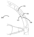
図1は、一実施形態による遠心遮断クラッチ100を例示する。この遠心遮断クラッチ100は、飛行機のローターが回転するのを機械的に阻止する機械的機構である。一実施形態において、遠心遮断クラッチは金属(例えば鋼か、チタンか、またはアルミニウム)あるいは複合材料(例えば炭素繊維またはケブラーR)により構成される。他の実施形態内において、遠心遮断クラッチを構成するために他の材料を用いることができることに注意されたい。
FIG. 1 illustrates a centrifugal shut-off
一実施形態において、この遠心遮断クラッチは、複数の摩擦パッド101と、複数のたわみ部材103と、複数の停止タブ105とを具えた円形の環状体である。摩擦パッド101は、0.1から0.5までの如き高摩擦係数を与えるブレーキパッド材料(石綿か、有機化合物か、または半金属配合物)からなる。他の摩擦係数を用いることができることに注意されたい。たわみ部材103は、一実施形態による第1の端107と第2の端109とをそれぞれ具える湾曲したアームである。一実施形態において、このたわみ部材103は「L」字形状である。たわみ部材103の第1の端107は遠心遮断クラッチ100に結合される。たわみ部材103のそれぞれの第2の端109は、遠心遮断クラッチに結合されずに摩擦パッド101に結合される。接着剤または締結具(例えばねじまたはリベット)の如き他の機構を用い、摩擦パッド101をたわみ部材103の第2の端に結合することができる。
In one embodiment, the centrifugal shut-off clutch is a circular annular body that includes a plurality of
停止タブ105は、たわみ部材103があらかじめ規定した移動範囲の外に移動するの阻止する。従って、停止タブ105はたわみ部材103が損傷(すなわち破損)するのを阻止する。図1に示すように、停止タブ105は遠心遮断クラッチ100の中心に向けて突出する。一実施形態において、この停止タブ105は、たわみ部材103の第2の端109に直近する遠心遮断クラッチ100の場所に配される。
The
さて、図2を参照すると、一実施形態によるローターアセンブリー200が例示されている。このローターアセンブリー200はローター201を含み、その一実施形態において16インチの半径を有すると共に炭素繊維複合材料から作られ、他の実施形態においてはアルミニウム製のハブに装着される炭素繊維複合羽根から作られる。他の実施形態において、ローター201はアルミニウム製のハブに装着される木質羽根か、または炭素繊維複合ハブに装着される木質羽根から作られる。このローターは、モーターアセンブリーに締結した単一部品であってよい。ローター201は、ハブに装着される羽根を具えることができるか、またはハブと一体の単一部品として製造することができる。ハブは、ローター201の羽根が接続すると共に実施形態によってはモーターを覆う形状に作られる中央構造体を装備する。
Now referring to FIG. 2, a
一実施形態において、ローターアセンブリー200はまた、モーターをも含む。このモーターは、回転部203(一部)と固定部205とを含む。一実施形態において、この回転部203は固定部205と同心であり、径方向流動モーターとして知られている。この実施形態において、固定部205はモーターの内側リングを形成することができ、外回転モーターとして知られている。いくつかの実施形態において、モーターの部品はこのモーターの全体がローターのハブ内に嵌合するように偏平であり、前方に飛行する際に空気流に対して低抵抗をもたらす。ローター201はモーターの回転部203に装着される。従って、モーターの回転部203が回転すると、ローター201もまた回転する。モーターの固定部205は飛行機の推進ブームに装着される。いくつか実施形態において、モーターは永久磁石モーターであって、電子モーター制御器により制御される。この電子モーター制御器は電流をモーターに正確な順序で送り、ローター201が望ましい速度または望ましいトルクで回転することを可能にする。
In one embodiment, the
図2に示すように、遠心遮断クラッチ100はローターアセンブリー200に含まれる。一実施形態において、遠心遮断クラッチ100は、ねじ部材またはリベットの如き締結具を介してモーターの回転部203に結合される。遠心遮断クラッチはモーターの回転部203に取り付けられ、たわみ部材103がローターアセンブリー200に含まれるモーターの固定部205に対して高摩擦パッド101を予圧するようになっている。モーターの回転部203が静止している場合、高摩擦パッド101はローター201の回転を阻止するモーターの固定部205に対して押圧する。すなわち、摩擦パッド101により与えられる摩擦は動きに抵抗する。図3Aは、係合した場合の遠心遮断クラッチ100を例示する。特に、図3Aはモーターの回転部203が回転していない、または速度閾値よりも低速で回転している場合、モーターの固定部205に対して摩擦パッド101を予圧するたわみ部材103を示している。
As shown in FIG. 2, the
モーターの固定部205に対して摩擦パッド101を予圧するたわみ部材103によって与えられた摩擦トルクに打ち勝つトルクをモーターが提供する場合、モーターの回転部203が回転し、それによりローター201もまた回転させる。回転部203が回転している場合、それぞれのたわみ部材103に取り付けられるか、またはその一部であるプルーフマスは、それぞれのたわみ部材に取り付けられた高摩擦パッド101に遠心力を加える。この遠心力は、たわみ部材103によって与えられる固定部205への予圧を相殺する。
When the motor provides a torque that overcomes the friction torque provided by the
モーターの回転部203の速度が増加すると、遠心力が増大してたわみ部材103がモーターの固定部205から離れるように曲がり始めるため、結果として摩擦トルクが減少し、それによって摩擦パッド101の係合が外れる。摩擦パッド101は閾速度にてモーターの固定部205から完全に係合が外れ、摩擦パッド101からの如何なる摩擦トルクなしで回転部203およびローター201が自由に回転することを可能にする。特に、閾回転速度での遠心力は、たわみ部材103を外側に曲げさせ、それによって摩擦パッド101がモーターの固定部205と接触状態にはないという結果をもたらす。停止タブ105は、たわみ部材103が余りにも極端に外側へと曲がってたわみ部材103に損傷を与えることを阻止する。図3Bは、モーターの固定部205から完全に係合が外れた摩擦パッド101を例示する。図3Bに示すように、摩擦パッド101はすでにモーターの固定部205と接触状態ではなく、たわみ部材103の第2の端109が停止タブ105と接触状態にある。モーターの回転部203の速度が閾速度よりも低速に減少すると、たわみ部材103は、図3Aに示すように、モーターの固定部205に対して摩擦パッド101を予圧し始める。
When the speed of the rotating part 203 of the motor increases, the centrifugal force increases and the bending
プルーフマス計算
前述したように、それぞれのたわみ部材103に取り付けられるか、またはその一部であるプルーフマスは、それぞれのたわみ部材103に取り付けた高摩擦パッド101に遠心力を加える。一実施形態において、このプルーフマスは以下の変数に従って計算される。
τ=遠心遮断クラッチにより加えられるトルク
ωr=遠心遮断クラッチによって加えられるトルクがない場合の速度
Fn=モーターの固定部205に対する摩擦パッド101の力
Ff=μFn=摩擦力
R=モーターの固定部205の半径
mP=プルーフマスの質量
μ=摩擦パッド101の摩擦係数
Proof Mass Calculation As described above, the proof mass attached to or a part of each
τ = torque applied by the centrifugal shut-off clutch ω r = speed when there is no torque applied by the centrifugal shut-off clutch F n = force of the
たわみ部材103がτ(0rpm)=τ0=μF0Rであるような予圧トルクを与えていると仮定する。0rpmでの予圧は、遮断クラッチ100により与えられる望ましい制動トルクを表す。一実施形態において、遠心力は以下に示すような上の変数の関数として表される。
Fn(ω)=F0−mPRω2
Fn(ω)=(τ0/μR)−mPRω2 (1)
τ(ω)=μRFn(ω)
τ(ω)=μR{(τ0/μR)−mPRω2)}
τ(ω)=τ0−μmPR2ω2 (2)
It is assumed that the
F n (ω) = F 0 −m P Rω 2
F n (ω) = (τ 0 / μR) −m P Rω 2 (1)
τ (ω) = μRF n (ω)
τ (ω) = μR {(τ 0 / μR) −m P Rω 2 )}
τ (ω) = τ 0 -μm P R 2 ω 2 (2)
式(1)に記述したように、速度ωでのモーターの固定部205に対する摩擦パッド101の力は、プルーフマス(mPRω2)の求心力の大きさを差し引いたゼロRPM(F0)でのモーターに対する摩擦パッドの力と等しい。速度(ω)でのトルク(τ(ω))は、式(1)をトルク(τ(ω))のための式へと代入することによって得られる。
As described in the equation (1), the force of the
ωrが規定された場合、以下に示す式(3)により表されるように、プルーフマスの質量を決定するために式(2)を単純化することができる。
0=τ0−μmPR2ω2
mP=τ0/μR2ωr 2 (3)
If ω r is defined, equation (2) can be simplified to determine the mass of the proof mass, as represented by equation (3) below.
0 = τ 0 −μm P R 2 ω 2
m P = τ 0 / μR 2 ω r 2 (3)
式(3)に基づくと、τ0が10ナノメートルであってRが2.75インチの場合、ωrが毎分500回転(rpm)であってμは0.5であり、それでプルーフマスの質量は例えば3.3ポンドである。ωrが1500rpmに変化した場合、その場合にはプルーフマスは例えば0.4ポンドである。 Based on equation (3), if τ 0 is 10 nanometers and R is 2.75 inches, ω r is 500 revolutions per minute (rpm) and μ is 0.5, so the proof mass The mass of is, for example, 3.3 pounds. If omega r is changed to 1500 rpm, in which case the proof mass is 0.4 lbs, for example.
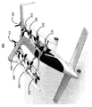
飛行機
さて、図4を参照すると、図2に示すローターアセンブリー200を組み込んだ飛行機400が例示されている。この飛行機400は垂直揚力のためにローターアセンブリー200を使用する。特に、このローターアセンブリー200は飛行機400を地面から持ち上げて制御を維持するのに十分な推力を提供する。適切な高度にある場合、一実施形態におけるローターアセンブリー200は、これらが垂直揚力のために用いられるので止められる。前方飛行プロペラ401が前方推進のために用いられる。上述した遠心遮断クラッチ100は、上述した使用状態にない場合、ローターアセンブリー200を静止状態に保つ。
Airplane Referring now to FIG. 4, an
特定の実施形態に照らしてこの説明を与えたけれども、この与えられた教示から当業者らは多くの他の実施形態を推測することができることを理解しよう。さらにまた、この記載した説明内の構成要素の特定の名称や、用語の強調表記,特質,データー構成,あるいは他のあらゆる構造的またはプラグラム形態は、特に言及しない限り必須または重要ではなく、記述した発明またはその特徴を実行する機構が異なる名称や構成またはプロトコルを有することができる。さらに、飛行コンピューター500の構成要素を含むこのシステムのいくつか形態をハードウェアとソフトウェアとの組み合わせを介し、または完全にハードウェアの要素にて実行することができる。また、ここで記述した種々のシステム構成要素の間での特定な機能性の分割は必須ではなく、単一のモジュールまたはシステム構成要素により行われる機能を代わりに多数の構成要素によって行うことができ、多数の構成要素により行われる機能を代わりに単一の構成要素によって行うことができる。同様に、特に言及するか、または論理的に必要ではない限り、方法ステップが行われる指令は必須ではない。 Although this description has been given in the context of particular embodiments, it will be appreciated that many other embodiments can be inferred from this given teaching by those skilled in the art. Furthermore, the specific names of the components in the description, the term highlighting, the nature, the data structure, or any other structural or program form are not essential or important unless otherwise stated. The mechanism for carrying out the invention or its features may have different names, configurations or protocols. In addition, some forms of this system, including components of the flight computer 500, can be implemented through a combination of hardware and software, or entirely in hardware components. Also, the particular functionality division between the various system components described herein is not essential, and the functions performed by a single module or system component can be performed by multiple components instead. A function performed by multiple components can instead be performed by a single component. Similarly, unless otherwise stated or logically necessary, a directive in which a method step is performed is not required.
明記した場合を除き、「選択」または「演算」または「決定」などの如き用語を使用した説明は、コンピューターシステムのメモリーまたはレジスターまたは他のこのような情報格納や伝達または表示機器内の物理的(電子的)量として表されるデーターを操作して転換するコンピューターシステムや同様な電子演算機器の動作および処理を意味する。 Except where noted, explanations using terms such as “select” or “operation” or “decision” refer to the physical or physical contents of a computer system memory or register or other such information storage or transmission or display equipment. It refers to the operation and processing of computer systems and similar electronic computing devices that manipulate and convert data expressed as (electronic) quantities.
記述した実施形態の電子的構成要素は、必要とされる目的のために特別に構成することができるか、あるいはコンピューター内に記憶したコンピュータープログラムによって選択的に作動または再構成される1台以上の汎用コンピューターを具えることができる。このようなコンピュータープログラムは、フロッピー(登録商標)ディスクや光ディスク,DVD,CD-ROM,磁気・光ディスクを含むあらゆる種類のディスクか、読み出し専用メモリー(ROM),ランダムアクセスメモリー(RAM),EPROM,EEPROM,磁気または光カード,特定用途向け集積回路(ASIC),あるいは電子的指令を格納するのに適すると共にコンピューターのシステムバスにそれぞれ結合されるあらゆる種類の媒体の如き、コンピューターによって読み取り可能な記憶媒体に格納することができるが、これらに限定されない。 The electronic components of the described embodiments can be specially configured for the required purposes, or can be selectively activated or reconfigured by a computer program stored in the computer. Can have a general purpose computer. Such computer programs can be any kind of disk, including floppy disks, optical disks, DVDs, CD-ROMs, magnetic / optical disks, read only memory (ROM), random access memory (RAM), EPROM, EEPROM. On any computer readable storage medium, such as any type of media suitable for storing electronic commands, magnetic or optical cards, application specific integrated circuits (ASICs), or electronic system buses, respectively. It can be stored, but is not limited to these.
最後に、この明細書にて用いた用語が主として読みやすさおよび説明の目的のために選択され、本発明の内容を正確に描写または限定するように選択されていない可能性があることに注意すべきである。従って、この開示は本発明の範囲を限定ではなく、例示することを意図している。 Finally, it is noted that the terms used in this specification are selected primarily for readability and explanatory purposes and may not be selected to accurately depict or limit the content of the invention. Should. Accordingly, this disclosure is intended to illustrate, not limit, the scope of the invention.
Claims (16)
固定部および回転部を具え、前記回転部が前記ローターに結合されるモーターと、
このモーターの前記回転部に結合される遠心遮断クラッチであって、複数の摩擦パッドと内周および外周を含む一体構成のリングとを具え、この一体構成のリングが当該一体構成のリングの内周に沿って同じ方向に前記内周から周方向に延在する複数のたわみ部材を含むように形成された遠心遮断クラッチと
を具え、前記一体構成のリングは、この一体構成のリングの中央に向けて内周から突出する複数の停止タブをさらに含むように形成され、これら停止タブのそれぞれは前記複数のたわみ部材の1つが当該停止タブの位置を越えて屈曲するのを阻止するように形成され、
前記複数のたわみ部材は、前記ローターの回転速度が閾値よりも低い場合には前記モーターの固定部に対し前記複数の摩擦パッドを予圧して前記遠心遮断クラッチを係合させ、前記ローターの回転速度が前記閾値以上の場合には前記モーターの固定部から前記複数の摩擦パッドが離れて前記遠心遮断クラッチを係合解除させるように形成されていることを特徴とするローターアセンブリー。 With the rotor,
A motor comprising a fixed part and a rotating part, wherein the rotating part is coupled to the rotor;
A centrifugal shut-off clutch coupled to the rotating portion of the motor, comprising a plurality of friction pads and an integral ring including an inner circumference and an outer circumference, and the integral ring is an inner circumference of the integral ring. And a centrifugal shut-off clutch formed to include a plurality of flexible members extending in the circumferential direction from the inner circumference in the same direction along the ring, and the integral ring is directed toward the center of the integral ring. A plurality of stop tabs protruding from the inner periphery, each of the stop tabs being formed to prevent one of the plurality of flexure members from bending beyond the position of the stop tab. ,
Wherein the plurality of deflection members, when the rotational speed of the front kilometers Ta is lower than the threshold engaged with the centrifugal cutoff clutch to preload said plurality of friction pads relative to the fixed part of the motor, the rotor rotor assembly when the rotational speed is equal to or larger than the threshold value, characterized that you have formed a plurality of friction pads wherein the centrifugal blocking clutch is away from the fixed part of the motor so as to disengage.
Applications Claiming Priority (3)
| Application Number | Priority Date | Filing Date | Title |
|---|---|---|---|
| US13/298,154 | 2011-11-16 | ||
| US13/298,154 US8602942B2 (en) | 2011-11-16 | 2011-11-16 | Centrifugal de-clutch |
| PCT/US2012/064978 WO2013074603A1 (en) | 2011-11-16 | 2012-11-14 | Centrifugal de-clutch |
Related Child Applications (1)
| Application Number | Title | Priority Date | Filing Date |
|---|---|---|---|
| JP2015064928A Division JP2015147574A (en) | 2011-11-16 | 2015-03-26 | Centrifugal de-clutch |
Publications (2)
| Publication Number | Publication Date |
|---|---|
| JP2014526412A JP2014526412A (en) | 2014-10-06 |
| JP5723073B2 true JP5723073B2 (en) | 2015-05-27 |
Family
ID=48279558
Family Applications (2)
| Application Number | Title | Priority Date | Filing Date |
|---|---|---|---|
| JP2014530010A Active JP5723073B2 (en) | 2011-11-16 | 2012-11-14 | Centrifugal cutoff clutch |
| JP2015064928A Pending JP2015147574A (en) | 2011-11-16 | 2015-03-26 | Centrifugal de-clutch |
Family Applications After (1)
| Application Number | Title | Priority Date | Filing Date |
|---|---|---|---|
| JP2015064928A Pending JP2015147574A (en) | 2011-11-16 | 2015-03-26 | Centrifugal de-clutch |
Country Status (10)
| Country | Link |
|---|---|
| US (2) | US8602942B2 (en) |
| EP (1) | EP2718186A4 (en) |
| JP (2) | JP5723073B2 (en) |
| KR (1) | KR101441281B1 (en) |
| CN (1) | CN103717493B (en) |
| AU (1) | AU2012339688B2 (en) |
| BR (1) | BR112014005846A2 (en) |
| CA (1) | CA2837668C (en) |
| IL (2) | IL230344A (en) |
| WO (1) | WO2013074603A1 (en) |
Families Citing this family (27)
| Publication number | Priority date | Publication date | Assignee | Title |
|---|---|---|---|---|
| USD706705S1 (en) * | 2011-12-17 | 2014-06-10 | Zee.Aero Inc. | Rotor blade |
| US9540103B2 (en) * | 2014-06-24 | 2017-01-10 | Kitty Hawk Corporation | Passive deployment mechanism for lift fan |
| DE102015001704B4 (en) * | 2015-02-13 | 2017-04-13 | Airbus Defence and Space GmbH | Vertical launching aircraft |
| DE102015106833A1 (en) * | 2015-04-30 | 2016-11-03 | Johnson Electric Germany GmbH & Co. KG | Centrifugal brake for Venetian blind drives |
| EP3096150B1 (en) * | 2015-05-12 | 2018-12-19 | Rolls-Royce Corporation | Speed sensing system |
| CN106956989B (en) | 2015-09-12 | 2020-03-27 | 奥的斯电梯公司 | Elevator overspeed governor |
| US10994836B2 (en) * | 2015-12-11 | 2021-05-04 | Amazon Technologies, Inc. | Feathering propeller clutch mechanisms |
| EP3184425B1 (en) | 2015-12-21 | 2018-09-12 | AIRBUS HELICOPTERS DEUTSCHLAND GmbH | Multirotor aircraft |
| US10208818B2 (en) * | 2016-11-17 | 2019-02-19 | Caterpillar Inc. | Apparatus having automatic centrifugal brakes for wheels |
| US9783288B1 (en) * | 2016-12-07 | 2017-10-10 | Kitty Hawk Corporation | Lift fan position lock mechanism |
| EP3354559B1 (en) | 2017-01-26 | 2019-04-03 | AIRBUS HELICOPTERS DEUTSCHLAND GmbH | A thrust producing unit with at least two rotor assemblies and a shrouding |
| EP3354566B1 (en) | 2017-01-26 | 2019-07-03 | AIRBUS HELICOPTERS DEUTSCHLAND GmbH | A thrust producing unit with at least two rotor assemblies and a shrouding |
| EP3366586B1 (en) | 2017-02-27 | 2020-08-19 | AIRBUS HELICOPTERS DEUTSCHLAND GmbH | A thrust producing unit with at least two rotor assemblies and a shrouding |
| EP3366582B1 (en) | 2017-02-28 | 2019-07-24 | AIRBUS HELICOPTERS DEUTSCHLAND GmbH | A multirotor aircraft with an airframe and a thrust producing units arrangement |
| US10558219B2 (en) | 2017-09-21 | 2020-02-11 | Loon Llc | Systems and methods for controlling an aerial vehicle using lateral propulsion and vertical movement |
| EP3470332B1 (en) | 2017-10-13 | 2020-04-22 | AIRBUS HELICOPTERS DEUTSCHLAND GmbH | A multirotor aircraft with an airframe and at least one wing |
| US11174019B2 (en) | 2017-11-03 | 2021-11-16 | Joby Aero, Inc. | VTOL M-wing configuration |
| US10495659B2 (en) * | 2017-11-06 | 2019-12-03 | Rolls-Royce Corporation | Speed and position sensing systems |
| FR3075862B1 (en) * | 2017-12-22 | 2020-08-28 | Safran Aircraft Engines | TURBOMACHINE BLOWER BRAKE DEVICE |
| EP3581490B1 (en) | 2018-06-13 | 2021-01-13 | AIRBUS HELICOPTERS DEUTSCHLAND GmbH | A multirotor aircraft with a thrust producing unit that comprises an aerodynamically optimized shrouding |
| EP3656669B1 (en) | 2018-11-26 | 2021-01-13 | AIRBUS HELICOPTERS DEUTSCHLAND GmbH | A vertical take-off and landing multirotor aircraft with at least eight thrust producing units |
| PL3702277T3 (en) | 2019-02-27 | 2021-07-19 | Airbus Helicopters Deutschland GmbH | A multirotor aircraft that is adapted for vertical take-off and landing (vtol) |
| EP3702276B1 (en) | 2019-02-27 | 2021-01-13 | AIRBUS HELICOPTERS DEUTSCHLAND GmbH | A multirotor joined-wing aircraft with vtol capabilities |
| US11220320B2 (en) | 2019-07-17 | 2022-01-11 | Aerostar International, Inc. | Lateral propulsion systems and architectures for high altitude balloons |
| CN114607714B (en) * | 2022-05-12 | 2022-08-23 | 上海航天壹亘智能科技有限公司 | Magnetic clutch for wind power generation |
| CN115016291B (en) * | 2022-07-13 | 2023-11-10 | 西北工业大学 | Wind field information-based anti-interference attitude control system and method for aircraft |
| JP7755555B2 (en) | 2022-08-02 | 2025-10-16 | 本田技研工業株式会社 | Power supply system for vertical take-off and landing aircraft |
Family Cites Families (48)
| Publication number | Priority date | Publication date | Assignee | Title |
|---|---|---|---|---|
| US1425555A (en) | 1922-08-15 | Airship | ||
| GB391548A (en) | 1932-01-20 | 1933-05-04 | Stuart Turner Ltd | Improvements in and relating to clutch couplings for power transmission purposes, particularly the starting of engines and variable speed ratio transmission |
| US2295503A (en) * | 1940-09-19 | 1942-09-08 | Hydraulic Brake Co | Brake |
| US2806569A (en) * | 1953-11-09 | 1957-09-17 | Sr Harvey A Keeling | Motor vehicle fan regulating mechanism |
| US2827136A (en) * | 1955-03-11 | 1958-03-18 | Cleveland Electric Motor Compa | Drive-released brake for motors and the like |
| US2951540A (en) * | 1956-11-05 | 1960-09-06 | Gen Motors Corp | Propeller brake |
| GB1349748A (en) * | 1970-10-13 | 1974-04-10 | Timson E A | Reel brake |
| US3856238A (en) | 1972-04-14 | 1974-12-24 | F Malvestuto | Aircraft transporter |
| DE2528719A1 (en) | 1975-06-27 | 1977-01-20 | Bosch Gmbh Robert | Centrifugal clutch |
| JPS5493686U (en) * | 1977-12-16 | 1979-07-03 | ||
| DE2822638C2 (en) * | 1978-05-24 | 1982-05-19 | Robert Bosch Gmbh, 7000 Stuttgart | Slip clutch |
| JPS58156732A (en) * | 1982-03-15 | 1983-09-17 | Mitsubishi Electric Corp | Emergency brake gear |
| JPH0681395B2 (en) | 1989-08-07 | 1994-10-12 | 住友電装株式会社 | Winding type noise prevention resistance wire end processing method |
| JPH0382699A (en) | 1989-08-28 | 1991-04-08 | Aretsukusu Denshi Kogyo Kk | Small-sized vertical take-off and landing aircraft |
| BR9106696A (en) | 1990-07-25 | 1993-06-08 | Sadleir Vtol Aircraft Co Pty L | FLUSHING UNIT FOR VTOL AIRCRAFT |
| JPH04312218A (en) * | 1991-04-05 | 1992-11-04 | Toyota Motor Corp | Centrifugal clutch |
| JP2700734B2 (en) | 1991-09-20 | 1998-01-21 | 川崎重工業株式会社 | Vertical takeoff and landing aircraft |
| CH685692A5 (en) | 1992-01-29 | 1995-09-15 | Sky Disc Holding Sa C O Norasi | Aircraft. |
| US5280828A (en) | 1992-02-07 | 1994-01-25 | Mattel, Inc. | Speed governor for rotational drive |
| US5601160A (en) * | 1994-10-20 | 1997-02-11 | Case Corporation | Hydraulically actuated brake assembly for an off-highway implement |
| US5853145A (en) * | 1997-01-09 | 1998-12-29 | Cartercopters, Llc | Rotor head for rotary wing aircraft |
| IT1293677B1 (en) * | 1997-08-01 | 1999-03-08 | Finmeccanica Spa | ROTOR BRAKE FOR A HELICOPTER. |
| DE19745492B4 (en) | 1997-10-15 | 2005-06-09 | Wobben, Aloys, Dipl.-Ing. | Vertical airplane |
| US5988328A (en) * | 1998-03-17 | 1999-11-23 | Dana Corporation | Spring set centrifugally released brake |
| US6277463B1 (en) * | 1998-08-28 | 2001-08-21 | Mcdonnell Douglas Corporation | Composite member having increased resistance to delamination and method of making same |
| JP2001322598A (en) * | 2000-05-16 | 2001-11-20 | Japan Aviation Electronics Industry Ltd | Remotely controlled unmanned helicopter |
| WO2002064426A1 (en) | 2001-02-14 | 2002-08-22 | Airscooter Corporation | Ultralight coaxial rotor aircraft |
| US6708921B2 (en) * | 2001-04-20 | 2004-03-23 | Bell Helicopter Textron, Inc. | Composite flapping flexure |
| US6568630B2 (en) | 2001-08-21 | 2003-05-27 | Urban Aeronautics Ltd. | Ducted vehicles particularly useful as VTOL aircraft |
| US20030062443A1 (en) | 2001-10-02 | 2003-04-03 | Joseph Wagner | VTOL personal aircraft |
| US6561456B1 (en) | 2001-12-06 | 2003-05-13 | Michael Thomas Devine | Vertical/short take-off and landing aircraft |
| JP4085716B2 (en) | 2002-06-26 | 2008-05-14 | トヨタ自動車株式会社 | Vertical take-off and landing aircraft |
| US6845831B2 (en) * | 2002-12-05 | 2005-01-25 | Deere & Company | PTO shaft brake |
| US6969026B2 (en) | 2002-12-20 | 2005-11-29 | Tsuneo Kayama | Aircraft |
| US6935470B1 (en) * | 2002-12-31 | 2005-08-30 | Robert P. Smith, Jr. | Disk brake |
| US6843447B2 (en) | 2003-01-06 | 2005-01-18 | Brian H. Morgan | Vertical take-off and landing aircraft |
| FR2853064B1 (en) | 2003-03-28 | 2005-06-24 | ON-BOARD FLIGHT MANAGEMENT SYSTEM FOR AIRCRAFT | |
| JP2004312218A (en) | 2003-04-04 | 2004-11-04 | Fuji Photo Film Co Ltd | Digital camera and image playback device |
| FR2855811B1 (en) * | 2003-06-05 | 2005-08-05 | Eurocopter France | ROTOR BLADE WITH NOT VARIABLE, FOR ROTORS CARENES, IN PARTICULAR HELICOPTERS |
| EP1730023A4 (en) * | 2004-03-11 | 2007-11-07 | Benmaxx Llc | Lightweight reinforced brake drum and method for making same |
| US7159817B2 (en) | 2005-01-13 | 2007-01-09 | Vandermey Timothy | Vertical take-off and landing (VTOL) aircraft with distributed thrust and control |
| US20080054121A1 (en) | 2006-05-11 | 2008-03-06 | Urban Aeronautics Ltd. | Ducted fan VTOL vehicles |
| US20080197639A1 (en) * | 2007-02-15 | 2008-08-21 | Mark Brander | Bi-directional wind turbine |
| WO2008103079A1 (en) * | 2007-02-22 | 2008-08-28 | Husqvarna Aktiebolag | Retarding device for a rotational cutting machine |
| US20090216392A1 (en) | 2007-07-11 | 2009-08-27 | Piasecki Aircraft Corporation | Vectored thruster augmented aircraft |
| JP2009083798A (en) | 2007-10-03 | 2009-04-23 | Japan Aerospace Exploration Agency | Control method of electric vertical take-off and landing aircraft |
| KR100887836B1 (en) | 2007-11-22 | 2009-03-09 | 현대자동차주식회사 | Hub for clutch disc of automobile and clutch disc including same |
| CA2670247A1 (en) | 2008-07-09 | 2010-01-09 | Magna Powertrain Usa, Inc. | Pump assembly with radial clutch for use in power transmission assemblies |
-
2011
- 2011-11-16 US US13/298,154 patent/US8602942B2/en active Active
-
2012
- 2012-11-14 AU AU2012339688A patent/AU2012339688B2/en active Active
- 2012-11-14 BR BR112014005846A patent/BR112014005846A2/en not_active IP Right Cessation
- 2012-11-14 CN CN201280036467.0A patent/CN103717493B/en active Active
- 2012-11-14 EP EP12849916.7A patent/EP2718186A4/en not_active Withdrawn
- 2012-11-14 CA CA2837668A patent/CA2837668C/en active Active
- 2012-11-14 WO PCT/US2012/064978 patent/WO2013074603A1/en not_active Ceased
- 2012-11-14 JP JP2014530010A patent/JP5723073B2/en active Active
- 2012-11-14 KR KR1020147004539A patent/KR101441281B1/en active Active
-
2013
- 2013-11-04 US US14/070,820 patent/US9115774B2/en active Active
-
2014
- 2014-01-06 IL IL230344A patent/IL230344A/en active IP Right Grant
- 2014-09-08 IL IL234536A patent/IL234536A/en active IP Right Grant
-
2015
- 2015-03-26 JP JP2015064928A patent/JP2015147574A/en active Pending
Also Published As
| Publication number | Publication date |
|---|---|
| AU2012339688B2 (en) | 2015-01-22 |
| CN103717493B (en) | 2015-12-02 |
| US8602942B2 (en) | 2013-12-10 |
| AU2012339688A1 (en) | 2014-01-16 |
| JP2015147574A (en) | 2015-08-20 |
| BR112014005846A2 (en) | 2017-03-28 |
| JP2014526412A (en) | 2014-10-06 |
| EP2718186A4 (en) | 2015-05-20 |
| NZ619855A (en) | 2015-12-24 |
| US20140318907A1 (en) | 2014-10-30 |
| EP2718186A1 (en) | 2014-04-16 |
| WO2013074603A1 (en) | 2013-05-23 |
| IL234536A (en) | 2016-06-30 |
| CN103717493A (en) | 2014-04-09 |
| CA2837668C (en) | 2015-07-28 |
| NZ704805A (en) | 2016-01-29 |
| KR20140035530A (en) | 2014-03-21 |
| US20130118856A1 (en) | 2013-05-16 |
| IL230344A (en) | 2014-09-30 |
| KR101441281B1 (en) | 2014-09-17 |
| US9115774B2 (en) | 2015-08-25 |
| CA2837668A1 (en) | 2013-05-23 |
Similar Documents
| Publication | Publication Date | Title |
|---|---|---|
| JP5723073B2 (en) | Centrifugal cutoff clutch | |
| US8640985B2 (en) | Co-rotating stacked rotor disks for improved hover performance | |
| US9540103B2 (en) | Passive deployment mechanism for lift fan | |
| US9267561B2 (en) | Rotor brake control system | |
| US20150132104A1 (en) | Variable geometry lift fan mechanism | |
| US10377473B2 (en) | Disconnecting a rotor | |
| US12157555B1 (en) | Propeller ground stop mechanism | |
| JP2018537355A (en) | Redundant aircraft propulsion system using co-rotating propellers joined by wing tip connectors | |
| US11770055B2 (en) | Electric machine with integrated controller | |
| JP6507885B2 (en) | Vacuum pump | |
| JP5457437B2 (en) | Simplified system for controlling propeller blade settings for aircraft turboshaft engines | |
| NZ704805B2 (en) | Centrifugal de-clutch | |
| NZ619855B2 (en) | A rotor assembly with a centrifugal de-clutch | |
| JP2014517203A (en) | Vertical axis windmill braking device | |
| US10697507B2 (en) | Gear protection subassembly | |
| US9739326B2 (en) | Rotor brake with integrated impeller | |
| Quan | Airframe Design | |
| JP2000186510A (en) | Turbine engine |
Legal Events
| Date | Code | Title | Description |
|---|---|---|---|
| A521 | Request for written amendment filed |
Free format text: JAPANESE INTERMEDIATE CODE: A523 Effective date: 20140306 |
|
| A621 | Written request for application examination |
Free format text: JAPANESE INTERMEDIATE CODE: A621 Effective date: 20140306 |
|
| A871 | Explanation of circumstances concerning accelerated examination |
Free format text: JAPANESE INTERMEDIATE CODE: A871 Effective date: 20140306 |
|
| A975 | Report on accelerated examination |
Free format text: JAPANESE INTERMEDIATE CODE: A971005 Effective date: 20140811 |
|
| A131 | Notification of reasons for refusal |
Free format text: JAPANESE INTERMEDIATE CODE: A131 Effective date: 20140826 |
|
| A601 | Written request for extension of time |
Free format text: JAPANESE INTERMEDIATE CODE: A601 Effective date: 20141126 |
|
| A602 | Written permission of extension of time |
Free format text: JAPANESE INTERMEDIATE CODE: A602 Effective date: 20141203 |
|
| A521 | Request for written amendment filed |
Free format text: JAPANESE INTERMEDIATE CODE: A523 Effective date: 20141218 |
|
| TRDD | Decision of grant or rejection written | ||
| A01 | Written decision to grant a patent or to grant a registration (utility model) |
Free format text: JAPANESE INTERMEDIATE CODE: A01 Effective date: 20150224 |
|
| A61 | First payment of annual fees (during grant procedure) |
Free format text: JAPANESE INTERMEDIATE CODE: A61 Effective date: 20150326 |
|
| R150 | Certificate of patent or registration of utility model |
Ref document number: 5723073 Country of ref document: JP Free format text: JAPANESE INTERMEDIATE CODE: R150 |
|
| S531 | Written request for registration of change of domicile |
Free format text: JAPANESE INTERMEDIATE CODE: R313531 |
|
| S533 | Written request for registration of change of name |
Free format text: JAPANESE INTERMEDIATE CODE: R313533 |
|
| R350 | Written notification of registration of transfer |
Free format text: JAPANESE INTERMEDIATE CODE: R350 |
|
| R250 | Receipt of annual fees |
Free format text: JAPANESE INTERMEDIATE CODE: R250 |
|
| R250 | Receipt of annual fees |
Free format text: JAPANESE INTERMEDIATE CODE: R250 |
|
| R250 | Receipt of annual fees |
Free format text: JAPANESE INTERMEDIATE CODE: R250 |
|
| R250 | Receipt of annual fees |
Free format text: JAPANESE INTERMEDIATE CODE: R250 |
|
| S111 | Request for change of ownership or part of ownership |
Free format text: JAPANESE INTERMEDIATE CODE: R313113 |
|
| R350 | Written notification of registration of transfer |
Free format text: JAPANESE INTERMEDIATE CODE: R350 |
|
| R250 | Receipt of annual fees |
Free format text: JAPANESE INTERMEDIATE CODE: R250 |
|
| R250 | Receipt of annual fees |
Free format text: JAPANESE INTERMEDIATE CODE: R250 |
|
| R250 | Receipt of annual fees |
Free format text: JAPANESE INTERMEDIATE CODE: R250 |
|
| R250 | Receipt of annual fees |
Free format text: JAPANESE INTERMEDIATE CODE: R250 |
|
| R250 | Receipt of annual fees |
Free format text: JAPANESE INTERMEDIATE CODE: R250 |