JP5742009B2 - Earth / Solar / Zero Energy Housing - Google Patents
Earth / Solar / Zero Energy Housing Download PDFInfo
- Publication number
- JP5742009B2 JP5742009B2 JP2011054736A JP2011054736A JP5742009B2 JP 5742009 B2 JP5742009 B2 JP 5742009B2 JP 2011054736 A JP2011054736 A JP 2011054736A JP 2011054736 A JP2011054736 A JP 2011054736A JP 5742009 B2 JP5742009 B2 JP 5742009B2
- Authority
- JP
- Japan
- Prior art keywords
- hot water
- floor
- air
- storage tank
- heat
- Prior art date
- Legal status (The legal status is an assumption and is not a legal conclusion. Google has not performed a legal analysis and makes no representation as to the accuracy of the status listed.)
- Expired - Fee Related
Links
- XLYOFNOQVPJJNP-UHFFFAOYSA-N water Substances O XLYOFNOQVPJJNP-UHFFFAOYSA-N 0.000 claims description 411
- 238000011084 recovery Methods 0.000 claims description 163
- 238000009423 ventilation Methods 0.000 claims description 51
- 239000003507 refrigerant Substances 0.000 claims description 34
- 230000005611 electricity Effects 0.000 claims description 26
- BZHJMEDXRYGGRV-UHFFFAOYSA-N Vinyl chloride Chemical compound ClC=C BZHJMEDXRYGGRV-UHFFFAOYSA-N 0.000 claims description 12
- 238000003466 welding Methods 0.000 claims description 6
- 230000000903 blocking effect Effects 0.000 claims description 2
- VEXZGXHMUGYJMC-UHFFFAOYSA-M Chloride anion Chemical compound [Cl-] VEXZGXHMUGYJMC-UHFFFAOYSA-M 0.000 claims 1
- 239000002985 plastic film Substances 0.000 claims 1
- 238000005338 heat storage Methods 0.000 description 80
- 238000009413 insulation Methods 0.000 description 15
- 238000010586 diagram Methods 0.000 description 10
- 239000011810 insulating material Substances 0.000 description 10
- 238000010276 construction Methods 0.000 description 7
- 238000010438 heat treatment Methods 0.000 description 7
- 238000000034 method Methods 0.000 description 5
- 238000010248 power generation Methods 0.000 description 5
- 101100043261 Caenorhabditis elegans spop-1 gene Proteins 0.000 description 4
- 230000000694 effects Effects 0.000 description 4
- 238000004378 air conditioning Methods 0.000 description 3
- 238000001816 cooling Methods 0.000 description 3
- JOYRKODLDBILNP-UHFFFAOYSA-N Ethyl urethane Chemical compound CCOC(N)=O JOYRKODLDBILNP-UHFFFAOYSA-N 0.000 description 2
- 230000008901 benefit Effects 0.000 description 2
- 238000005265 energy consumption Methods 0.000 description 2
- 230000003203 everyday effect Effects 0.000 description 2
- 229920006248 expandable polystyrene Polymers 0.000 description 2
- 239000003673 groundwater Substances 0.000 description 2
- 238000009434 installation Methods 0.000 description 2
- 239000010410 layer Substances 0.000 description 2
- 239000000463 material Substances 0.000 description 2
- 238000005192 partition Methods 0.000 description 2
- 230000009467 reduction Effects 0.000 description 2
- 239000008399 tap water Substances 0.000 description 2
- 235000020679 tap water Nutrition 0.000 description 2
- 238000010792 warming Methods 0.000 description 2
- 239000004793 Polystyrene Substances 0.000 description 1
- 230000009471 action Effects 0.000 description 1
- 238000009412 basement excavation Methods 0.000 description 1
- 238000009835 boiling Methods 0.000 description 1
- 230000008859 change Effects 0.000 description 1
- 238000006243 chemical reaction Methods 0.000 description 1
- 150000001805 chlorine compounds Chemical class 0.000 description 1
- 238000004140 cleaning Methods 0.000 description 1
- 230000002354 daily effect Effects 0.000 description 1
- 238000005553 drilling Methods 0.000 description 1
- 238000005516 engineering process Methods 0.000 description 1
- 239000004744 fabric Substances 0.000 description 1
- 239000006260 foam Substances 0.000 description 1
- 238000005259 measurement Methods 0.000 description 1
- 239000002184 metal Substances 0.000 description 1
- 238000012986 modification Methods 0.000 description 1
- 230000004048 modification Effects 0.000 description 1
- 238000009428 plumbing Methods 0.000 description 1
- 229920002223 polystyrene Polymers 0.000 description 1
- 238000012545 processing Methods 0.000 description 1
- 230000001172 regenerating effect Effects 0.000 description 1
- 238000003303 reheating Methods 0.000 description 1
- 239000011347 resin Substances 0.000 description 1
- 229920005989 resin Polymers 0.000 description 1
- 239000002356 single layer Substances 0.000 description 1
- 239000007787 solid Substances 0.000 description 1
- 230000001360 synchronised effect Effects 0.000 description 1
- 238000012546 transfer Methods 0.000 description 1
- 125000000391 vinyl group Chemical group [H]C([*])=C([H])[H] 0.000 description 1
- 229920002554 vinyl polymer Polymers 0.000 description 1
- 239000002699 waste material Substances 0.000 description 1
Images




Classifications
-
- F—MECHANICAL ENGINEERING; LIGHTING; HEATING; WEAPONS; BLASTING
- F24—HEATING; RANGES; VENTILATING
- F24T—GEOTHERMAL COLLECTORS; GEOTHERMAL SYSTEMS
- F24T10/00—Geothermal collectors
- F24T10/10—Geothermal collectors with circulation of working fluids through underground channels, the working fluids not coming into direct contact with the ground
- F24T10/13—Geothermal collectors with circulation of working fluids through underground channels, the working fluids not coming into direct contact with the ground using tube assemblies suitable for insertion into boreholes in the ground, e.g. geothermal probes
- F24T10/17—Geothermal collectors with circulation of working fluids through underground channels, the working fluids not coming into direct contact with the ground using tube assemblies suitable for insertion into boreholes in the ground, e.g. geothermal probes using tubes closed at one end, i.e. return-type tubes
-
- Y—GENERAL TAGGING OF NEW TECHNOLOGICAL DEVELOPMENTS; GENERAL TAGGING OF CROSS-SECTIONAL TECHNOLOGIES SPANNING OVER SEVERAL SECTIONS OF THE IPC; TECHNICAL SUBJECTS COVERED BY FORMER USPC CROSS-REFERENCE ART COLLECTIONS [XRACs] AND DIGESTS
- Y02—TECHNOLOGIES OR APPLICATIONS FOR MITIGATION OR ADAPTATION AGAINST CLIMATE CHANGE
- Y02E—REDUCTION OF GREENHOUSE GAS [GHG] EMISSIONS, RELATED TO ENERGY GENERATION, TRANSMISSION OR DISTRIBUTION
- Y02E10/00—Energy generation through renewable energy sources
- Y02E10/10—Geothermal energy
Landscapes
- Engineering & Computer Science (AREA)
- Life Sciences & Earth Sciences (AREA)
- General Life Sciences & Earth Sciences (AREA)
- Sustainable Development (AREA)
- Sustainable Energy (AREA)
- Chemical & Material Sciences (AREA)
- Combustion & Propulsion (AREA)
- Mechanical Engineering (AREA)
- General Engineering & Computer Science (AREA)
- Central Heating Systems (AREA)
Description
本発明は、建物の基礎部に外部との通気口を設置せず、1階床下内部の空気を外気と遮断して密封状態とし、建物の室内に取付けた全熱交換型換気扇が室内側に供給する新鮮な外気を、建物の1階床下部に送り込むと共に、1階床下の基礎底盤に下部をU字形に形成した複数の地中熱回収パイプを、両端を基礎底盤より1階床下部に突き出すように地中に埋設し、地中熱回収パイプの一端には送風機を取付け、その送風機を作動させる事により1階床下内部の空気が地中熱回収パイプに吸い込まれ、その地中熱回収パイプに吸い込まれた空気は、冬期は地中熱により地中熱回収パイプの中で暖められると共に、1階床下の基礎底盤に温水蓄熱槽を設置し、その温水蓄熱槽に自然冷媒ヒートポンプ給油機で沸かしたお湯をお風呂で使用した後、温かい風呂の残り湯を温水蓄熱槽の中に流して溜湯させる事により1階床下内部の空気がさらに暖められ、また、夏期は地中熱により地中熱回収パイプの中で冷やされた空気が1階床下部に供給されると共に、その1階床下の空気をダクトを経由して各階の天井内部に供給し、天井内部に供給された空気が各室天井に設けたガラリより室内に供給されて、室温調整を行うための装置に関するものである。The present invention does not install an air vent to the base of the building, and shuts off the air inside the first floor floor from the outside air so that it is in a sealed state. The fresh outside air to be supplied is sent to the lower part of the first floor of the building, and a plurality of underground heat recovery pipes with a U-shaped lower part formed on the foundation floor under the first floor, both ends of the foundation floor from the foundation floor to the lower part of the first floor It is buried in the ground so as to protrude, and a blower is attached to one end of the underground heat recovery pipe. By operating the fan, the air inside the first floor is sucked into the underground heat recovery pipe, and the underground heat recovery is performed. The air sucked into the pipe is warmed in the geothermal heat recovery pipe by the underground heat in the winter season, and a hot water heat storage tank is installed in the foundation floor under the first floor, and a natural refrigerant heat pump oiler is installed in the hot water heat storage tank. After using the hot water boiled in the bath, By flowing the remaining hot water from the hot water bath into the hot water storage tank, the air inside the 1st floor is further warmed, and in the summer, the air is cooled in the underground heat recovery pipe by geothermal heat. Is supplied to the lower part of the first floor, and the air under the first floor is supplied to the ceiling of each floor via a duct, and the air supplied to the interior of the ceiling is supplied to the room from the gallery provided on the ceiling of each room. The present invention also relates to an apparatus for adjusting the room temperature.
従来の、小規模な住宅における室温調整は、夏期にはクーラーを使用し、冬期には電気、ガス、石油等のエネルギーを利用して冷暖房を行って来たが、近年では地球温暖化防止の観点から、エネルギー消費に伴うCO2排出量の削減が急務となり、エネルギー消費量の削減や、さらに自然エネルギーへの代替が早急に望まれている。 Conventional room temperature adjustment in small houses has been using air conditioners in the summer and cooling and heating using energy such as electricity, gas, and oil in the winter. From the viewpoint, it is an urgent need to reduce CO2 emissions accompanying energy consumption, and reduction of energy consumption and further replacement with natural energy are urgently desired.
これに伴い、自然エネルギーの利用手段として、現在、一般的に普及しているものは、太陽エネルギーを利用した、太陽熱温水器(熱効率50〜60%)と太陽光発電(変換効率10〜15%)があるが、いずれも、太陽エネルギーだけを利用する省エネ技術は天候に左右され易く、不安定な点から単独では利用が出来ず、他のエネルギーと兼用して利用されて来たため、なお一層の改良が求められている。 Along with this, as a means of utilizing natural energy, what is currently widely used is a solar water heater (thermal efficiency 50-60%) and solar power generation (conversion efficiency 10-15%) using solar energy. However, in both cases, energy-saving technology that uses only solar energy is easily affected by the weather and cannot be used alone because of instability, and has been used in combination with other energy. There is a need for improvements.
これに対して、地下4〜5メートルの地中は、年間を通じて安定した温度を保つことから、夏期は外気と比べて低温となり、冬期は外気と比べて暖温となる。そのため、従来からこのような地中熱を利用した設備は、大型の建物や公共設備等で実験的に施工されているが、その利用方法は、冬の間に自然界で出来た氷を保存しておき、その氷を夏期に地下に設けた蓄熱槽に移して冷水を作り、その冷水を各室に循環させて冷房を行うことが一般的であり、大掛かりな工事が必要となり、しかも、定期的に蓄熱層に氷を補充しなければならず、小規模な住宅用としては不向きであった。 On the other hand, since the underground of 4 to 5 meters below the ground maintains a stable temperature throughout the year, it is cooler than the outside air in the summer and warmer than the outside in the winter. For this reason, facilities that use geothermal heat have been experimentally constructed in large buildings and public facilities, but the method of use is to preserve the ice made in nature during the winter. In general, it is common to transfer the ice to a heat storage tank in the basement in the summer to make cold water, circulate the cold water to each room and cool it. Therefore, it was necessary to replenish the heat storage layer with ice, which was not suitable for small-scale housing.
さらに、地中熱を利用したヒートポンプ方式で、家庭内の給湯と、室内の冷暖房を行う方法も行われているが、水平ループ方式(地中に深さ1〜2メートルの堀を堀り、そこに採熱用パイプを這わせて埋設する)では、建て坪100m2の住宅の熱源を得るために400〜600メートルの採熱用パイプを埋設することが必要であり、又、垂直ループ方式(地中に深さ50〜100メートルの井戸を堀り、そこに採熱用パイプを埋設する)では2本の井戸が必要となり、一般住宅用で300〜500万円の費用を要すると共に、ヒートポンプの稼動コスト(電気代)が、深夜電力を利用した電気温水器の約75%かかるといった問題があった。Furthermore, in the heat pump system using geothermal heat, there is also a method of domestic hot water supply and indoor air conditioning, but the horizontal loop method (deep a 1-2 m deep moat in the ground, In order to obtain a heat source for a house with a floor area of 100 m 2 , it is necessary to embed a 400-600 meter heat collecting pipe, and a vertical loop system. (To dig a well of 50-100 meters deep in the ground and embed a pipe for heat collection there) requires two wells, and costs 3 to 5 million yen for general housing, There is a problem that the operating cost (electricity cost) of the heat pump is about 75% of that of an electric water heater using midnight power.
また、平成15年7月に建築基準法が改正され、「シックハウス対策」として、居室の24時間換気(1時間で居室体積の0.5回分を換気させる事)が義務づけられた。 In July 2003, the Building Standards Law was amended to require 24-hour ventilation of the room (to ventilate 0.5 times the volume of the room in one hour) as a “sick house measure”.
そこで、本出願人は、特許文献1に記載された、建築基準法に対応できる「アース・ソーラーシステム(二層式)」を発明し出願した。この発明によれば、貯水タンクと、貯温水タンクの2つのタンクを地中に埋設し、その双方のタンク内に、外気取入口から各室の24時間給気パイプに連通する熱交換パイプを配管し、貯水タンクを雨水又は地下水又は水道水で満たすと共に、貯温水タンクは太陽熱温水器からの温水で満たし、前記、熱交換パイプに設けた開閉バルブを操作する事により、夏期においては、冬期の冷たい外気で冷やしておいた貯水タンク内の冷水を利用して、外気を貯水タンク内の熱交換パイプを経由させ、暑い外気を冷やして各室に送り込むため、効率よく冷風運転を行うことが出来る。また、冬期においては、夏期の暑い外気で温めておいた貯水タンクの弱温水に冷たい外気を熱交換バイプを経由して暖めると共に、さらに太陽熱温水器を利用した、貯温水タンク内の温水中の熱交換パイプを経由するため、各室に温風を送り込むことが可能となる。
しかしながら、本出願人の出願した特許文献1の発明においては、貯水タンクと貯温水タンクの2つのタンクを必要としたため、配管が複雑になり、開閉バルブの数も増え、高価格になると共に、施工するための工期も長く必要であった。 However, in the invention of Patent Document 1 filed by the present applicant, two tanks, a water storage tank and a hot water storage tank, are required, so the piping becomes complicated, the number of open / close valves increases, and the price increases. A long construction period was also required.
そこで、本出願人は、特許文献2に記載された、「アース・ソーラーシステム(一層式)」を発明し出願した。この発明によれば、建物の下部の地中に、建物の基礎部と−体に構成されたコンクリート製タンクを構築し、コンクリート製タンク内に熱交換パイプを配管し、コンクリート製タンク内を雨水、又は水道水、又は地下水で満たし、全熱交換型換気扇からの供給空気をコンクリート製タンク内の熱交換パイプに導き、夏期は、全熱交換型換気扇からの供給空気を、地中熱で冷やされたコンクリート製タンク内の水と、熱交換パイプとの間で熱交換して冷やした後、給気パイプを経由して各階に給気し、冬期は、太陽熱温水器からの温水を、コンクリート製タンク内に循環させて、コンクリート製タンク内を温水状態とし、全熱交換型換気扇からの供給空気を、コンクリート製タンク内の熱交換パイプに導き、コンクリート製タンク内の温水と、熱交換パイプとの間で熱交換して暖めた後、給気パイプを経由して各階に給気した事により、各室に温風を送り込むことが可能となる。
しかしながら、本出願人の出願した特許文献2の発明においても、コンクリート製タンクを必要としたため、高価格になると共に、施工するための工期も長く必要であった。 However, in the invention of
そこで、本出願人は、特許文献3に記載された、「アース・ソーラーシステム(地中熱回収パイプ方式)」を発明して出願した。この発明によれば、建物の基礎部に外部との通気口を設置せず、1階床下内部の空気を外気と遮断して密封状態とし、建物の室内に取付けた全熱交換型換気扇が室内側に供給する新鮮な外気を、建物の1階床下内部に送り込むと共に、1階床下の基礎底盤に下部をU字形に成形した複数の地中熱回収パイプを、両端を基礎底盤より1階床下内部に突き出すように地中に埋設し、地中熱回収パイプの一端には送風機を取付け、その送風機を作動させる事により1階床下内部の空気が地中熱回収パイプに吸い込まれ、その地中熱回収パイプに吸い込まれた空気は、冬期は地中熱により地中熱回収パイプの中で暖められると共に、さらに、1階床下部に設けた温水蓄熱槽に太陽熱温水器で温めた温水を循環させて1階床下内部の空気を暖め、また、夏期は1階床下部に設けた温水蓄熱槽に太陽熱温水器からの温水を循環させず、地中熱により地中熱回収パイプの中で冷やされた空気が1階床下内部に供給され、その1階床下内部の空気をダクトを通して各階の天井内部に供給し、天井内部に供給された空気を各室天井に設けたガラリより室内に供給した事により、冬期には弱暖房された暖かい空気を各室に供給すると共に、夏期には弱冷風された涼しい空気を各室に送り込むことが可能となった。
しかしながら、本出願人の出願した特許文献3の発明においても、雨や曇りの日が続いた場合、太陽熱温水器のお湯の温度が上がらず、雨や曇りの日と、晴天の日の温度差が大きいといった問題が発生した。 However, even in the invention of
そこで、本出願人は、特許文献4に記載された、「アース・ソーラーシステム改良型(地中熱回収パイプ方式)」を発明して出願した。この発明によれば、冬期においては、風呂の残り湯を1階床下部に設けた温水蓄熱槽に流して溜湯させると共に、温水蓄熱槽をコストを抑えるためにゴム等(塩化ビニールシート等)の安価な材料で製作したため、雨や曇りの日が続いた場合でも、温水蓄熱槽に温かいお湯を溜湯することが可能となり、冬期には弱暖房された暖かい空気を各室に供給すると共に、夏期には、1階床下部に設けた温水蓄熱槽に太陽熱温水器からの温水を循環させず、地中熱により地中熱回収パイプの中で冷やされた空気が1階床下内部に供給され、その1階床下の空気をダクトを通して各階の天井内部に供給し、天井内部に供給された弱冷風された涼しい空気を各室に送り込むことが可能となった。
しかしながら、本出願人の出願した特許文献4の発明においても、冬期においては温水蓄熱槽に温かいお湯を供給するため、基本的には太陽熱温水器のお湯を利用すると共に、雨や曇りの日が続いた場合には、給湯器からのお湯を利用していたため、雨や曇りの日が続いた場合において、お風呂にお湯を供給するためのガス代金(電気代金)や、日常、洗面所や台所でお湯を使用するための費用がかかるといった問題が残った。 However, even in the invention of
また、従来より地中熱交換機を利用した建物の空調換気システムとして知られている、特許文献5に記載したジオパワーシステムの場合は、冬期において、地中熱だけでは暖房効果(地下5mでも地中温度は約18度前後だから、外気を地中熱により暖めても、それ以下の温度にしかならない)が低く、さらに価格が高く、一般住宅に施工する場合はコストの面で問題があった。
さらに、太陽エネルギーを利用するソーラーシステムとして知られている、特許文献6に記載したOMソーラーの場合、雨や曇りの日が続いた場合には暖房効果が下がるため補助暖房装置が必要になるといった問題と、さらに、夏期においては冷風運転が出来ないといった欠点があった。
本発明は、このような、従来の欠点に鑑みて、自然との調和を図る事を目的とし、石油、ガス、電気等の人工エネルギーの浪費を抑え、太陽熱や、風呂の温かい残り湯や、地中の地中熱を有効に利用して、住宅の室温調整を行うものであり、エネルギーコストが低く、構造が簡単な冷暖房装置を提供する事を課題とする。 In view of such conventional drawbacks, the present invention aims at harmony with nature, suppresses waste of artificial energy such as oil, gas, electricity, solar heat, hot remaining hot water in the bath, An object of the present invention is to provide a cooling / heating device with a low energy cost and a simple structure that adjusts the room temperature of a house by effectively using underground heat.
本出願人の出願した特許文献1、特許文献2、特許文献3、特許文献4による発明では、上記のような問題が発生したため、当社では、新たに、特許文献4の発明を改良して、太陽電池パネルと自然冷媒ヒートポンプ給湯機を利用して、太陽の光で発電して自然冷媒ヒートポンプ給湯機でお湯を沸かし、そのお湯を貯湯タンクに溜湯してお風呂に供給し、冬期においては、その風呂の残り湯を建物の1階床下に設置した温水蓄熱槽に供給する事により、本出願人が以前に出願した特許文献1、特許文献2、特許文献3、特許文献4より更にエネルギーコストが低い商品を開発し、本発明を特許出願すると同時に、新製品の発売に踏み切る事とした。In the invention according to Patent Document 1,
かかる課題を解決するため、請求項1に記載の発明は、建物の基礎部に外部との通気口を設置せず、1階床下内部の空気を外気と遮断して密封状態とし、建物の室内に取付けた全熱交換型換気扇が室内側に供給する新鮮な外気を、建物の1階床下内部に送り込むと共に、1階床下の基礎底盤に下部をU字型に成形した複数の地中熱回収パイプを、両端を基礎底盤より1階床下内部に突き出すように地中に埋設し、地中熱回収パイプの一端には送風機を取付け、その送風機を作動させる事により1階床下内部の空気が地中熱回収パイプに吸い込まれ、冬期は、地中熱により地中熱回収パイプの中で暖められて1階床下内部の空気を暖めると共に、1階床下の基礎底盤に、長方形の2枚の塩化ビニールシートの端部を溶着して水枕状に形成し、上面の塩化ビニールシートに風呂の残り湯の温水取入口と排水口のための穴を開け、その穴位置に合わせて、中央部に穴を開けた縦20cm、横25cmの塩化ビニールシートを溶着し、さらに中央部の穴に、温水取入口の入口の高さと排水口の出口の高さが、温水蓄熱槽に風呂の残り湯が満タン状態になるまで流入された状態で、上面の塩化ビニールシートの上部より15cm高くなるように、温水取入口と排水口を塩ビ管で形成して塩ビ溶接し、排水口の排水取込口を温水蓄熱槽の底部に配置した温水蓄熱槽を設置し、太陽電池パネルで発電された電気で自然冷媒ヒートポンプ給湯機に電力を供給して沸かした貯湯タンクのお湯を、お風呂で利用した後、温かい風呂の残り湯を1階床下に設置した温水蓄熱槽に流して留湯させると共に、温水蓄熱槽の上面に温度センサーを取付け、温水蓄熱槽のお湯の温度を温度センサーで検知し、温水蓄熱槽が定めた範囲内の温度を保つように、自然冷媒ヒートポンプ給湯機で沸かした貯湯タンクのお湯を、混 合弁で湯温を調整し、自然冷媒ヒートポンプ給湯機の貯湯タンクから温水蓄熱槽に給湯させる事により1階床下内部の空気がさらに暖められて弱温風となり、暖められた1階床下内部の空気は、各階天井内部に設けられたダクトの送風機を作動させる事により、1階床下内部からダクトを経由して各階の天井内部に送られ、天井に設けたガラリより室内に供給されて室内を暖める事を特徴とする。In order to solve such a problem, the invention according to claim 1 does not install a vent hole to the outside of the foundation of the building, blocks the air inside the first floor under the outside air from the outside air and seals it. The fresh heat supplied to the indoor side by the total heat exchange type exhaust fan attached to the inside of the building is sent to the interior of the first floor below the building, and the ground heat recovery is formed in a U-shaped lower part on the foundation floor under the first floor Pipes are buried in the ground so that both ends protrude from the foundation floor into the first floor, and a blower is attached to one end of the underground heat recovery pipe. By operating the blower, the air inside the first floor is grounded. It is sucked into the middle heat recovery pipe, and in the winter, it is heated in the ground heat recovery pipe by the ground heat to warm the air inside the first floor under the floor, and two rectangular chlorides on the foundation floor under the first floor The end of the vinyl sheet is welded to form a water pillow, and the top Make holes for the hot water intake and drain of the remaining hot water in the surface of the vinyl chloride sheet, and weld a 20cm long and 25cm wide vinyl chloride sheet with a hole in the center according to the hole position. Furthermore, the top surface of the vinyl chloride is in a state where the hot water intake inlet height and the drain outlet height are poured into the hot water storage tank until the remaining hot water in the bath is full. A hot water storage tank with a hot water intake and drain outlet formed of a PVC pipe and welded with vinyl chloride so that it is 15 cm higher than the upper part of the seat, and a drainage inlet of the drain outlet arranged at the bottom of the hot water storage tank, A hot water storage tank in which the hot water in a hot water storage tank boiled by supplying electricity to a natural refrigerant heat pump water heater with electricity generated by a solar panel is used in the bath, and the remaining hot water in the hot bath is installed under the floor on the first floor And let it stay in hot water, A temperature sensor is attached to the upper surface of the heat storage tank, the temperature of the hot water storage tank is detected by the temperature sensor, and the temperature of the hot water storage tank boiled by the natural refrigerant heat pump water heater is maintained so as to maintain the temperature within the range specified by the hot water storage tank. hot water, to adjust the hot water temperature in mixed joint, the first floor floor inside the air further warmed by hot water in the hot water storage tank from the hot water storage tank of natural refrigerant heat pump water heater to become a weak hot air, the first floor warmed The air inside the floor is sent to the ceiling of each floor via the duct from the inside of the first floor floor by operating the duct blower provided inside the ceiling of each floor, and supplied to the room from the gallery provided on the ceiling. It is characterized by warming the room.
請求項1に記載の発明によれば、冬期においては、建物の基礎部に外部との通気口を設置せず、1階床下内部の空気を外気と遮断して密封状態とし、建物の室内に取付けた全熱交換型換気扇が室内側に供給する新鮮な外気を、建物の1階床下内部に送り込むと共に、1階床下の基礎底盤に下部をU字形に成形した複数の地中熱回収パイプを、両端を基礎底盤より1階床下内部に突き出すように地中に埋設し、地中熱回収パイプの一端には送風機を取付け、その送風機を作動させる事により1階床下内部の空気が地中熱回収パイプに吸い込まれ、地中熱により地中熱回収パイプの中で暖められて1階床下内部の空気を暖めると共に、昼間、太陽光発電システムで発電した電力で、自然冷媒ヒートポンプ給湯機に電力を供給して沸かしたお湯を、お風呂で利用した後、温水蓄熱槽に流して溜湯したため、雨や曇りが続いた場合においても、1階床下部の空気の温度を地中熱だけに頼らず暖かくする事が可能となり、これまで排水溝に流していた温かい風呂の残り湯のエネルギーを再利用する事が可能となり、CO2の削減と省エネに貢献する事が可能となった。 According to the first aspect of the present invention, in the winter season, a ventilation hole is not installed on the foundation of the building, and the air inside the first floor is shut off from the outside air to be in a sealed state. The fresh outdoor air supplied to the indoor side by the installed total heat exchange type exhaust fan is sent to the inside of the floor under the first floor of the building, and a plurality of underground heat recovery pipes whose lower part is formed in a U shape on the foundation floor under the first floor. , Both ends are buried in the ground so as to protrude from the foundation bottom into the first floor, and a blower is attached to one end of the underground heat recovery pipe. By operating the blower, the air inside the first floor is underground It is sucked into the recovery pipe and heated by the underground heat in the underground heat recovery pipe to warm the air inside the floor under the first floor, and the electric power generated by the solar power generation system in the daytime is used to supply the natural refrigerant heat pump water heater. Hot water boiled by supplying After being used in the bath, the hot water was poured into the hot water storage tank and the hot water was stored, so even if it rained or cloudy, the temperature of the air at the bottom of the first floor could be warmed up without relying only on underground heat. It is possible to reuse the energy of the hot water remaining in the hot bath that was flowing through the drainage channel, and contribute to CO2 reduction and energy saving.
以下、この発明の実施の形態1について説明する。
[発明の実施の形態1]Embodiment 1 of the present invention will be described below.
Embodiment 1 of the Invention
図1及至図10には、この発明の実施の形態1を示す。 1 to 10 show a first embodiment of the present invention.
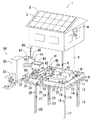
図1は、本発明の太陽電池パネルと自然冷媒ヒートポンプ給湯機と全熱交換型換気扇と温水蓄熱槽と地中熱回収パイプを利用した住宅の分解解説図である。以下に、太陽光と地中熱を利用した冷暖房システムを説明する。 FIG. 1 is an exploded explanatory view of a house using a solar cell panel, a natural refrigerant heat pump water heater, a total heat exchange type ventilation fan, a hot water heat storage tank, and a geothermal heat recovery pipe of the present invention. Below, the air conditioning system using sunlight and underground heat is demonstrated.
図1は、本発明のアース・ソーラー・ゼロエネルギー住宅を分かり易く説明するため、アース・ソーラー・ゼロエネルギー住宅を組み込んだ住宅1を分解解説図で示したものである。屋根2の上部に太陽電池パネル3を設置すると共に、その太陽電池パネル3で発電した電気で自然冷媒ヒートポンプ給湯機54を作動させて貯湯タンク50にお湯を蓄えると共に、基礎25には建物外部の空気が流入しないように外気との通気口を設置せず、基礎底盤52の中央部には温水蓄熱槽38が設置され、この温水蓄熱槽38には風呂43の残り湯を供給するための残り湯パイプ37が配管される。さらに、基礎底盤52の四隅には、下部をU字形に成形した4本の地中熱回収パイプ13、地中熱回収パイプ17、地中熱回収パイプ23、地中熱回収パイプ28が、両端を基礎底盤52より1階床下部に突き出すように地中に埋設される。 FIG. 1 is an exploded explanatory view showing a house 1 incorporating an earth, solar, and zero energy house in order to easily explain the earth, solar, and zero energy house of the present invention. The
このように構成されたアース・ソーラー・ゼロエネルギー住宅は、太陽電池パネル3で発電された電気で、自然冷媒ヒートポンプ給湯機54を作動させて貯湯タンク50にお湯を蓄えると共に、貯湯タンク50から給湯配管48を経由して風呂43に給湯され、さらに、風呂43で利用された後の温かい残り湯は、風呂43に備え付けられた残り湯パイプ37用の排水栓(図示せず)を抜く事により、残り湯パイプ37を経由して温水蓄熱槽38に溜湯される。また、基礎25の内側の基礎底盤52の四隅には、下部をU字形に成形した4本の地中熱回収パイプ13、地中熱回収パイプ17、地中熱回収パイプ23、地中熱回収パイプ28が設置されると共に、居室に取付けられた全熱交換型換気扇4で熱交換された室内側供給空気(新鮮な空気)は、給気導入ダクト5を経由して矢印7方向に送られ1階床下内部に給気される。 The earth / solar / zero-energy house constructed as described above uses the electricity generated by the
地中熱回収パイプ13、地中熱回収パイプ17、地中熱回収パイプ23、地中熱回収パイプ28は、直径が約100〜120ミリメートルの2本の塩ビパイプの下部を継手で継いで、下部をU字形に構成すると共に、基礎底盤52の四隅に設置し、基礎底盤52の上部に突き出す2本の塩ビパイプには、L字形のエルボ等の継手を取付け、2本の塩ビパイプに取付けたL字形のエルボ等の空気取入口と空気排出口が、基礎底盤52面に対して互いに直角になるように構成し、一方のエルボ等の先端には送風機(24時間換気システム排気ファン)を取付ける。上記で説明した、塩ビパイプを地中熱回収パイプとしてU字形に成形するためには、図2の拡大図で示すように、塩ビパイプ119、塩ビパイプ120の下部をU字形の継手121で継ぐ事により、1本の地中熱回収パイプとなる。 The geothermal
本発明において、地中熱回収パイプ13、地中熱回収パイプ17、地中熱回収パイプ23、地中熱回収パイプ28には塩ビパイプを使用し、地中に埋め込む深さは約5メートルである。その理由は、関東地区の地中4〜5メートルの地中温度は、年間を通して約17℃〜19℃と温度変化が少ないためです。また、地中熱回収パイプを地中に埋設させる施工方法としては、穴掘建柱車にオーガーを取付けて地面に掘削穴を掘り、その穴の中に地中熱回収パイプを埋設させる工法が、安価で、なおかつ工期を短縮させる事が可能な施工方法である。なお、穴掘建柱車とオーガーを使用する最大の理由は、土木作業等で利用している穴掘建柱車と、それに取付ける一般的なオーガーは掘削穴径が最大約45センチメートル、最大掘削深さが約5メートルのため、本発明の地中熱回収パイプを地中に埋設させる作業に適しており、さらに、穴掘建柱車とオーガーを容易に安価でレンタルする事が出来るといった利点があるためである。ちなみに、東京都足立区の、当社ショールーム(地下室付)では、毎日、地中1メートル、3メートル、5メートルの地中温度を測定しているが、その測定結果によると地中5メートルの地中温度は、5月〜6月の間で最低温度の17.1℃となり、11月〜12月の間で最高温度の19.3℃となる。外気の最低気温(2月頃)に対して地中5メートルの最低温度が5月〜6月となるのは、地表面の温度が地中に浸透するのに時間がかかるためです。夏期の最高温度が11月〜12月となるのも地表面の温度が地中に浸透するのに時間がかかるためです。 In the present invention, a PVC pipe is used for the underground
さらに、図1と図4で示すように、24時間換気システム用排気ファンに使用している送風機10、送風機20、送風機35、送風機40を作動させる事により、地中熱回収パイプ8が矢印143方向から吸い込んだ1階床下内部の空気は、図1の地中熱回収パイプ13の中を矢印12方向から矢印14方向に流れて地中熱により温度調整されて、地中熱回収パイプ9を経由して送風機10から1階床下内部に排出される。このようにして1階床下内部に排出された空気は矢印11方向に送風され、1階床下内部の空気と混ぜ合わされて温度調整が行われ、図4で示すように、矢印140方向から再び地中熱回収パイプ15に吸い込まれ、地中熱回収パイプ17の中を矢印16方向から矢印18方向に流れて地中熱により温度調整されて、地中熱回収パイプ19を経由して送風機20から1階床下内部に排出される。このようにして1階床下内部に排出された空気は矢印21方向に送風され、1階床下内部の空気と混ぜ合わされて温度調節が行われ、図4で示すように、矢印141方向から再び地中熱回収パイプ30に吸い込まれ、地中熱回収パイプ28の中を矢印29方向から矢印27方向に流れて地中熱により温度調整されて、地中熱回収パイプ33を経由して送風機35から1階床下内部に排出される。このようにして1階床下内部に排出された空気は矢印36方向に送風され、1階床下内部の空気と混ぜ合わされて温度調整が行われ、図4で示すように、矢印142方向から再び地中熱回収パイプ42に吸い込まれ、地中熱回収パイプ23の中を矢印24方向から矢印22方向に流れて地中熱により温度調整されて、地中熱回収パイプ41を経由して送風機40から1階床下内部に排出される。このようにして排出された空気は矢印39方向に送風され、1階床下内部の空気と混ぜ合わされて温度調節が行われ、図4で示すように、矢印143方向から再び地中熱回収パイプ8に吸い込まれる。このように基礎底盤52の四隅に配置された地中熱回収パイプ13、地中熱回収パイプ17、地中熱回収パイプ23、地中熱回収パイプ28の空気の吸込口(地中熱回収パイプ8、地中熱回収パイプ15、地中熱回収パイプ30、地中熱回収パイプ42)と、地中熱回収パイプの空気の排出口(地中熱回収パイプ9、地中熱回収パイプ19、地中熱回収パイプ33、地中熱回収パイプ41)が、互いに向き合うように構成する事により、1階床下内部の空気は床下内部で場所によって澱む事が無くなり、1階床下内部の空気の温度は均一の温度になるように調整される。 Further, as shown in FIGS. 1 and 4, by operating the
また、1階床下の基礎底盤52の四隅に地中熱回収パイプ13、地中熱回収パイプ17、地中熱回収パイプ23、地中熱回収パイプ28を埋め込む事が、互いの地中熱回収パイプ同士の距離を離す事となり、地中内部において地中熱回収パイプから発生する熱による、お互いの地中熱回収パイプ同士からの熱の干渉を少なくする事が可能となる。特に、狭い敷地に地中熱回収パイプを多数埋設した場合、地中熱回収パイプ同士が地中に放熱(回収)する地中熱により地中の中の温度が変化してしまい、地中熱回収のメリットが減少する。 Moreover, it is possible to embed the geothermal
このように、それぞれの地中熱回収パイプ13、地中熱回収パイプ17、地中熱回収パイプ23、地中熱回収パイプ28に各々1台の送風機を取付けて地中熱を回収する事により、地中熱を効率良く回収する事が可能となる。さらに、それぞれの地中熱回収パイプ13、地中熱回収パイプ17、地中熱回収パイプ23、地中熱回収パイプ28に独立して送風機を取付けた事により、1階床下内部の空気の温度が、夏(冬)の初期等に冷え(暖か)すぎる場合には、4本の地中熱回収パイプの内の数本の送風機を可動させ、その他の地中熱回収パイプの送風機を停止する事により、1階床下内部の温度を調整する事が可能となる。 In this way, by installing a single blower to each of the underground
なお、一般住宅の1階床下の基礎部、特にべた基礎(布基礎)においては、1階床下部の湿気を防ぐために外部と通気が良い構造となっているが、本発明においては、1階床下内部を外気温度調整槽として利用するため、外気が1階床下部に直接流入しないように1階床下内部が密封状態となるように構成される。 In addition, in the foundation part under the first floor of a general house, in particular, in the solid foundation (cloth foundation), in order to prevent moisture in the lower part of the first floor, the outside has good ventilation, but in the present invention, the first floor In order to use the inside of the underfloor as an outside air temperature control tank, the inside of the first floor is configured to be sealed so that the outside air does not flow directly into the lower part of the first floor.
以上のような構成により、図2により夏期における各室への冷風運転について解説する。 With the configuration as described above, the cold air operation to each room in the summer will be explained with reference to FIG.
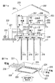
最初に、全熱交換型換気扇64、全熱交換型換気扇65から室内側に供給される空気(新鮮な空気)を1階床下104に給気する方法について説明する。1階室内Aの室内側吐出空気(よごれた室内空気)は、全熱交換型換気扇65に吸い込まれて室外に排気される。その際、全熱交換型換気扇65が排気する室内の空気(室内側吐出空気)と、室内に給気する外気(室外側吸込空気)とが全熱交換型換気扇65の内部で熱交換されると共に、吸い込んだ室外側吸込空気(新鮮な空気)は全て給気導入ダクト66を経由して1階床下104に導かれる。同様にして、2階室内Bの室内側吐出空気(よごれた室内空気)は、全熱交換型換気扇64に吸い込まれて室外に排気される。その際、全熱交換型換気扇64が排気する室内の空気(室内側吐出空気)と、室内に給気する外気(室外側吸込空気)とが全熱交換型換気扇64の中で熱交換されると共に、吸い込んだ室外側吸込空気(新鮮な空気)は全て給気導入ダクト67を経由して1階床下104に導かれる。 First, a method for supplying air (fresh air) supplied from the total heat exchange
このようにして、全熱交換型換気扇64、全熱交換型換気扇65を使用する事により、夏期における涼しい室内の空気を、外の暑い外気と入れ替える(換気する)際に、涼しい室内の空気の温度の上昇を最小限に抑える事が可能となる。 In this way, by using the total heat exchange
つづいて、このようにして1階床下104に導入された全熱交換型換気扇64、全熱交換型換気扇65からの外気(室外側吸込空気)が、どのようにして1階床下104で熱交換されて弱冷風になるかを説明する。給気導入ダクト66、給気導入ダクト67から導入された全熱交換型換気扇64、全熱交換型換気扇65からの外気は、1階床下104の空気と混ざり合い、地中熱回収パイプ71に取付けられた送風機72を作動させる事により、1階床下104の空気は、矢印70方向から地中熱回収パイプ71に吸い込まれ、地中熱回収パイプ71の中で地中熱により冷やされて弱冷風となり、送風機72より矢印73方向に示すように1階床下104に排気される。同様に、地中熱回収パイプ75に取付けられた送風機77を作動させる事により、1階床下104の空気は、矢印74方向から地中熱回収パイプ75に吸い込まれ、地中熱回収パイプ75の中で地中熱により冷やされて弱冷風となり、送風機77より矢印78方向に示すように1階床下104に排気される。同様に、地中熱回収パイプ76に取付けられた送風機80を作動させる事により、1階床下104の空気は、矢印79方向から地中熱回収パイプ76に吸い込まれ、地中熱回収パイプ76の中で地中熱により冷やされて弱冷風となり、送風機80より矢印81方向に示すように1階床下104に排気される。同様に、地中熱回収パイプ83に取付けられた送風機84を作動させる事により、1階床下104の空気は、矢印82方向から地中熱回収パイプ83に吸い込まれ、地中熱回収パイプ83の中で地中熱により冷やされて弱冷風となり、送風機84より矢印85方向に示すように1階床下104に排気される。 Subsequently, how the outside air (outdoor air intake air) from the total heat exchange
このようにして、1階床下104の中で弱冷風となった外気は、1階床を冷やす事により1階室内Aを冷やすと共に、弱冷風となった1階床下104の空気は、給気ダクト119に取付けられた送風機110を作動させる事により、給気ダクト119を経由して1階天井裏100に給気され、ガラリ106、ガラリ108より1階室内Aに給気されて1階室内Aを冷やす。同様に、給気ダクト111に取付けられた送風機115を作動させる事により、1階床下104の中で弱冷風となった外気は、給気ダクト111を経由して2階天井裏116に給気され、ガラリ113、ガラリ118より2階室内Bに給気されて2階室内Bを冷やす。 In this way, the outside air that has become weak air in the
なお、夏期においては、1階床下104に設置した温水蓄熱槽102には風呂97の残り湯を供給せず、夏期においては温水蓄熱槽102は利用しない。 In the summer, the remaining hot water of the
つづいて、図3で示す、冬期における各室の弱温風運転について説明する。 Subsequently, the operation of the warm air in each room in the winter shown in FIG. 3 will be described.
最初に、全熱交換型換気扇64、全熱交換型換気扇65から室内側に供給される空気(新鮮な空気)を1階床下104に給気する方法について説明する。1階室内Aの室内側吐出空気(よごれた室内空気)は、全熱交換型換気扇65に吸い込まれて室外に排気される。その際、全熱交換型換気扇65が排気する室内の空気(室内側吐出空気)と、室内に給気する外気(室外側吸込空気)とが全熱交換型換気扇65の中で熱交換されると共に、吸い込まれた室外側吸込空気(新鮮な空気)は全て給気導入ダクト66を経由して1階床下104に導かれる。同様にして、2階室内Bの室内側吐出空気(よごれた室内空気)は、全熱交換型換気扇64に吸い込まれて室外に排気される。その際、全熱交換型換気扇64が排気する室内の空気(室内側吐出空気)と、室内に給気する外気(室外側吸込空気)とが全熱交換型換気扇64の中で熱交換されると共に、吸い込まれた室外側吸込空気(新鮮な空気)は全て給気導入ダクト67を経由して1階床下104に導かれる。 First, a method for supplying air (fresh air) supplied from the total heat exchange
このようにして、全熱交換型換気扇64、全熱交換型換気扇65を使用する事により、冬期における室内の暖かい空気を、外の冷たい外気と入れ替える(換気する)際に、室内の暖かい空気の温度が下がるのを最小限に抑える事が可能となる。ちなみに、三菱電機株式会社のホームページでは、ロスナイ(全熱交換型換気扇)の熱交換機能を、「外気温度0℃、室内温度20℃、温度交換効率75%の場合」、室内温度20℃の空気をロスナイ(全熱交換型換気扇)で換気した場合、外気(0℃)の空気の温度は熱交換機の働きで15℃となって室内に給気(新鮮空気)されると説明している。 Thus, by using the total heat exchange
つづいて、このようにして1階床下104に導入された全熱交換型換気扇64、全熱交換型換気扇65からの外気(室外側吸込空気)が、どのようにして1階床下104で熱交換されて弱温風になるかを説明する。給気導入ダクト66、給気導入ダクト67から導入された全熱交換型換気扇64、全熱交換型換気扇65からの外気は、1階床下104の空気と混ざり合い、地中熱回収パイプ71に取付けられた送風機72を作動させる事により、1階床下104の空気は、矢印70方向から地中熱回収パイプ71に吸い込まれ、地中熱回収パイプ71の中で地中熱により暖められて弱温風となり、送風機72より矢印73方向に示すように1階床下104に排気される。同様に、地中熱回収パイプ75に取付けられた送風機77を作動させる事により、1階床下104の空気は、矢印74方向から地中熱回収パイプ75に吸い込まれ、地中熱回収パイプ75の中で地中熱により暖められて弱温風となり、送風機77より矢印78方向に示すように1階床下104に排気される。同様に、地中熱回収パイプ76に取付けられた送風機80を作動させる事により、1階床下104の空気は、矢印79方向から地中熱回収パイプ76に吸い込まれ、地中熱回収パイプ76の中で地中熱により暖められて弱温風となり、送風機80より矢印81方向に示すように1階床下104に排気される。同様に、地中熱回収パイプ83に取付けられた送風機84を作動させる事により、1階床下104の空気は、矢印82方向から地中熱回収パイプ83に吸い込まれ、地中熱回収パイプ83の中で地中熱により暖められて弱温風となり、送風機84より矢印85方向に示すように1階床下104に排気される。 Subsequently, how the outside air (outdoor air intake air) from the total heat exchange
さらに、冬期においては太陽電池パネル63で発電した電気で、自然冷媒ヒートポンプ給湯機122を動かして貯湯タンク93にお湯を蓄えると共に、貯湯タンク93から給湯配管91を経由して風呂97に給湯され、さらに、風呂97で利用された後の温かい残り湯は、風呂97に備え付けられた残り湯パイプ96用の排水栓(図示せず)を抜く事により、残り湯パイプ96を経由して温水蓄熱槽102に流され溜湯される。このようにして温水蓄熱槽102に溜湯された温かい風呂97の残り湯は1階床下104の空気を暖める。なお、温水蓄熱槽102から溢れ出る、温水蓄熱槽102の底部の冷めた風呂の残り湯は排水パイプ86を経由して矢印131方向に流れ排水溝87に排水される。 Furthermore, in the winter season, the electricity generated by the
このようにして、太陽電池パネル63で発電した電気で、自然冷媒ヒートポンプ給湯機122を動かして貯湯タンク93に蓄えたお湯を、風呂97で使用し、さらに、風呂97で利用した後の温かい残り湯を、1階床下104の基礎底盤に設置した温水蓄熱槽102に流して溜湯させる事により、地中熱回収パイプ71、地中熱回収パイプ75、地中熱回収パイプ76、地中熱回収パイプ83の中で地中熱により暖められた1階床下104の空気は、さらに温水蓄熱槽102に溜湯された温水により暖められ弱温風となる。 In this way, the hot water stored in the hot
このようにして、1階床下104で弱温風となった外気は、1階床を暖める事により1階室内Aを暖めると共に、弱温風となった1階床下104の空気は、給気ダクト119に取付けられた送風機110を作動させる事により、給気ダクト119を経由して1階天井裏100に給気されガラリ106、ガラリ108より1階室内Aに給気されて1階室内Aを暖める。同様に、給気ダクト111に取付けられた送風機115を作動させる事により、給気ダクト111を経由して2階天井裏116に給気され、ガラリ113、ガラリ118より2階室内Bに給気されて2階室内Bを暖める。 In this way, the outside air that has become the low temperature air under the
このように、冬期においては太陽電池パネル63で発電した電気で、自然冷媒ヒートポンプ給湯機122を動かして貯湯タンク93に蓄えた温水を風呂97で使用した後、風呂97で利用した後の温かい残り湯を、1階床下104の基礎底盤に設置した温水蓄熱槽102に流して溜湯させる事により、曇りや雨の日が続いた場合でも、風呂97で利用された後の温かい残り湯を温水蓄熱槽102に流して溜湯させる事により、地中熱回収パイプ71、地中熱回収パイプ75、地中熱回収パイプ76、地中熱回収パイプ83の中で地中熱により暖められた1階床下104の空気を、さらに暖め、弱温風として1階室内A、2階室内Bに給気する事が可能となる。 As described above, in the winter, the hot water stored in the hot
図5は、基礎底盤150に設置した温水蓄熱槽169と地中熱回収パイプと送風機と1階床下空間の空気の流れを説明する。 FIG. 5 illustrates the flow of air in the hot water
建物の基礎151の回りには基礎外断熱材152が施工され、建物の基礎底盤150の四隅には4本の地中熱回収パイプが配置される。温水蓄熱槽169は基礎底盤150の中央部に施工された断熱マット177(厚い発泡スチロールを使用)の上部に設置され、風呂で利用された後の温かい残り湯は、風呂(図示せず)からの残り湯パイプ173を経由して取入口172より温水蓄熱槽169に流され溜湯される。また、温水蓄熱槽169から溢れ出る、温水蓄熱槽169の底部の冷めた風呂の残り湯は、排水口175から排水パイプ174を経由して排水溝158に排水される。 Outside the foundation
つづいて、図6により温水蓄熱槽169の機能について説明する。 Next, the function of the hot water
図6は、温水蓄熱槽169の正面図、平面図、A―A断面図、B―B断面図である。温水蓄熱槽169は、長方形に切断された2枚のゴム状(塩化ビニールシート等)のシートの端部を溶着して水枕状に構成される。温水蓄熱槽169の上部に使用する上面ゴムシート180には取入口172、排水口175のための穴(図示せず)を開け、さらに、ゴム状シートを四角形状に切断(約20cm×約25cmの大きさに切断)して中央部には風呂の残り湯の取入口の穴(図示せず)を開けた溶着部171を作成し、溶着部171には塩ビ管で製作した取入口172を塩ビ溶接すると共に、同様に、ゴム状シートを四角形状に切断(約20cm×約25cmの大きさに切断)して中央部に排水口のための穴(図示せず)を開けた溶着部176を作成し、溶着部176に塩ビ管で製作した排水口175を塩ビ溶接し、上面ゴムシート180に開けられた穴位置(図示せず)に合わせて、溶着部171、溶着部176を溶着して取付ける。なお、現在では、砂漠等に人造湖を造る際に、砂漠等に大きな穴を掘り、その穴の底面にゴムシート(塩化ビニールシート等)を敷き詰め、そのゴムシート同士を溶着して一枚の大きな防水シートに加工して、水を貯める事も行われており、本発明のような温水蓄熱槽をゴムシートで作製した場合においても、長期に渡り保水性能や耐久性が保たれる。 FIG. 6 is a front view, a plan view, an AA cross-sectional view, and a BB cross-sectional view of the hot water
このようにして取付けた、取入口172から温水蓄熱槽内部189へ風呂の残り湯が流れ込む際には、B―B断面図で示すように、風呂の残り湯は取入口172から、溶着部171の直ぐ下に取付けられた固定部187を経由して矢印188方向で示すように温水蓄熱槽内部189に流れ込み、温水蓄熱槽内部189の上部側に温かい風呂の残り湯が溜湯される。このように温水蓄熱槽内部189に残り湯が供給された場合、温水蓄熱槽内部189の上部が温かく保たれ、温水蓄熱槽内部189の下部は、上部に比べて湯温度が低い状態となる。 When the remaining hot water of the bath flows into the hot water
また、温水蓄熱槽内部189から排水される冷めた風呂の残り湯は、A―A断面図で示すように、温水蓄熱槽内部189の下部の排水取込口191から矢印190方向に吸い込まれ、排水パイプ配管192を経由して排水口175から排水される。なお、風呂の残り湯を流入する温水蓄熱槽169に取付ける取入口172の入口の高さと、冷えた風呂の残り湯が温水蓄熱槽169から排出される排水口175の出口の高さは、温水蓄熱槽169がゴム状のシートで製作されるため、温水蓄熱槽169に風呂の残り湯が流入される事により、温水蓄熱槽169が水枕状に膨らむため、温水蓄熱槽169に風呂の残り湯が満タン状態になるまで流入された状態で、温水蓄熱槽169の上面ゴムシート180の最上部より上部(上面ゴムシート180の上部より、約10〜20センチメートル位高くなるのが良い)になるように構成されなければならない。 Moreover, the remaining hot water of the cooled bath drained from the hot water
このように温水蓄熱槽169を構成する事により、毎日、温かい風呂の残り湯が温水蓄熱槽169に供給され、雨や曇り日が続いた場合でも、1階床下内部の空気を暖める事が可能となる。さらに、排水取込口191を温水蓄熱槽内部189の底部に設置したため、風呂の残り湯の中に含まれる、温水蓄熱槽内部189の底部に蓄積する湯あか等を、冷めた風呂の残り湯と一緒に容易に排出する事が可能となる。 By configuring the hot water
つづいて、図7により、天井取付専用型全熱交換型換気扇229を設置する設置場所と機能について説明する。 Next, with reference to FIG. 7, the installation location and function for installing the ceiling-mounting total heat exchange
図7bに示すように、天井取付専用型全熱交換型換気扇229は、室内空気取入口228が天井取付専用型全熱交換型換気扇本体223の下面に設けられ、室内空気取入口228から吸込まれた室内の空気は、1本の排気用配管227を使って矢印で示す排気226方向(室外)に排気され、このように排気された室内の空気は図7aで示すようにフード203、フード205から室外に排気され、その際、天井取付専用型全熱交換型換気扇が排気226する室内の空気(室内側排出空気)と、フード203、フード205から吸い込まれ、外気取込配管224を経由して天井取付専用型全熱交換型換気扇229に吸込まれる外気225とが天井取付専用型全熱交換型換気扇本体223の内部で熱交換されると共に、吸込まれた外気225は複数本の給気パイプ231に分岐されて各居室に給気230されるように構成されている。 As shown in FIG. 7 b, the ceiling-mounted total heat exchange
このように構成された天井取付専用型全熱交換型換気扇229を、図7aで示すように1階部分の廊下Gの天井部分に天井取付専用型全熱交換型換気扇211を埋め込むように取付け、天井取付専用型全熱交換型換気扇211を稼働させる事により、各居室の室内空気が矢印213方向から廊下Gに流れ込むと共に、天井取付専用型全熱交換型換気扇211に吸込まれ、吸込まれた室内空気は天井取付専用型全熱交換型換気扇211内部で新鮮な外気と熱交換され、全ての給気は給気導入ダクト233を経由して1階床下234に供給される。同様に、2階部分の廊下Dの天井部分に天井取付専用型全熱交換型換気扇207を取付け、天井取付専用型全熱交換型換気扇207を稼働させる事により、各居室の室内空気が矢印210方向から廊下Dに流れ込むと共に、天井取付専用型全熱交換型換気扇207に吸込まれ、吸込まれた室内空気は天井取付専用型全熱交換型換気扇207内部で新鮮な外気と熱交換され、全ての給気は給気導入ダクト220を経由して1階床下234に供給される。このようにして1階床下234に供給された新鮮な外気は、図2、図3で説明したように、1階床下234より給気ダクトを経由して1階天井裏、2階天井裏に給気され、各室のガラリから居室に供給される。このようにして、各階の廊下に天井取付専用型全熱交換型換気扇を1台づつ設置する事により、居室のみならず廊下も含めて建物全体の室温調節が可能となるばかりでなく、さらにフィルターの清掃作業も各階1台の清掃で済むため簡単に行えるようになる。 The ceiling-mounting total heat exchange
図8は、本発明における住宅236を、次世代省エネタイプの断熱で構成した状態を示す。屋根の断熱に関しては、屋根断熱材237(一般的には、厚さ160ミリメートルの発泡ウレタン)を屋根内側に施工する。外壁の断熱に関しては、外壁断熱材239(一般的には、厚さ75ミリメートルの発泡ウレタン)を外壁内側に施工する。窓のサッシに関しては、各社から発売されている断熱等級4(次世代省エネタイプ)の断熱サッシ240を使用する。基礎の断熱に関しては、基礎外断熱材241(一般的には、厚さ50ミリメートルの発泡スチロール板)を基礎コンクリートの外側に施工する。但し、ここに書かれた断熱材の種類と材質に関しては、例えば、発泡スチロール板であっても、密度の違いにより断熱効果に変化が生じるため、同一メーカーであっても、密度により厚さが変わる場合があり得る。なお、一般的な次世代省エネタイプの住宅においては、1階床下、1階天井裏、2階天井裏に断熱材を施工しているが、本発明においては、住宅の各階の温度と各々室内同士の温度を出来るだけ均一に保つため、1階床下244や1階天井裏243、2階天井裏242には断熱材を施工しない。 FIG. 8 shows a state in which the
本発明における住宅の断熱性能に関しては、最大限の省エネ効果を得るためにも、図8で説明した次世代省エネタイプの断熱を必ず施工する必要がある。 Regarding the heat insulation performance of the house in the present invention, in order to obtain the maximum energy saving effect, the next-generation energy-saving type heat insulation described with reference to FIG.
図9は、図6で説明した温水蓄熱槽が、どのような状態で1階床下に設置されるか示す。温水蓄熱槽271は、1階床下の基礎底盤277の上面に設置された断熱マット254の上部に配置されると共に、その温水蓄熱槽271に対して、風呂273に設置されている温水蓄熱槽用の排水栓(図示せず)を抜く事により、風呂273の残り湯が残り湯パイプ272を経由して矢印270方向に送られ温水蓄熱槽271に溜湯されると共に、温水蓄熱槽271から溢れ出た、冷めた風呂の残り湯は、排水パイプ263を経由して矢印264方向から矢印266方向流れて排水溝267に排水される。 FIG. 9 shows how the hot water storage tank described in FIG. 6 is installed under the first floor. The hot water
図10は、太陽電池パネルと、その太陽電池パネルによって発電された電気を利用してお湯を沸かすための、自然冷媒ヒートポンプ給湯機と風呂と温水蓄熱槽を配管した状態を、分かり易く説明するため立体配管図で示した。太陽電池パネル280で発電された電気で自然冷媒ヒートポンプ給湯機279に電力を供給して沸かしたお湯を、お風呂285で利用した後、温かい風呂の残り湯を1階床下空間に設置した蓄熱温水槽288に流して留湯させる。 FIG. 10 is a diagram for explaining the state in which a natural refrigerant heat pump water heater, a bath, and a hot water heat storage tank are piped in order to boil hot water using electricity generated by the solar cell panel and the solar cell panel. Shown in a three-dimensional piping diagram. Hot water boiled by supplying electricity to the natural refrigerant heat
太陽電池パネル280で発電された電気で、自然冷媒ヒートポンプ給湯機279に電力を供給し、上水道292から供給された水がヒートポンプユニット296で外気の熱と熱交換されて温水となり貯湯タンク297に溜湯される。このようにして溜湯されたお湯は貯湯タンク297の中の給湯混合弁(図示せず)で水と混合されて適温となり給湯配管294を経由して風呂285に貯められる。この後、風呂285で使用された風呂285の残り湯は、風呂285に備え付けられた残り湯パイプ286用の排水栓(図示せず)を抜く事により、残り湯パイプ286を経由して温水蓄熱槽288に流され溜湯される。なお、温水蓄熱槽288から溢れ出る、温水蓄熱槽288の底部の冷めた風呂の残り湯は排水パイプ290を経由して排水される。 Electricity generated by the
以下、この発明の実施の形態2について説明する。
[発明の実施の形態2]The second embodiment of the present invention will be described below.
[
図11は、太陽電池パネルと、その太陽電池パネルによって発電された電気を利用してお湯を沸かすための、自然冷媒ヒートポンプ給湯機と風呂と温水蓄熱槽とを配管した状態を説明した立体配管図である。太陽電池パネル280で発電された電気で自然冷媒ヒートポンプ給湯機279に電力を供給して沸かしたお湯を、お風呂285で利用した後、温かい風呂の残り湯を1階床下に設置した蓄熱温水槽288に流して留湯させる事により、1階床下内部の空気を暖めることが可能となる。なお、実施の形態1の図10では、風呂285で使用された風呂285の残り湯だけを温水蓄熱槽288に給湯したが、この発明の実施の形態2の、図11では、給湯タンク297から給湯配管300を経由して供給されるお湯と、上水道301からの水を給湯混合弁302で湯温を調節すると供に、温水蓄熱槽288の上面に温度センサー306を取付け、温水蓄熱槽288のお湯の温度を温度センサー306で検知し、温水蓄熱槽288が設定した温度(最低温度と最高温度を設定して、最低温度になったら給湯タンク297からのお湯を温水蓄熱槽288に供給し、最高温度に達したらお湯の供給を停止する)を保つように、貯湯タンク297からのお湯を、給湯混合弁302で湯温調節して温水蓄熱槽288に給湯するように構成した。 FIG. 11 is a three-dimensional piping diagram illustrating a state where a natural refrigerant heat pump water heater, a bath, and a hot water heat storage tank are piped to boil hot water using electricity generated by the solar cell panel and the solar cell panel. It is. After using hot water boiled by supplying electricity to the natural refrigerant heat
このように、給湯タンク297から温水蓄熱槽288に温かい温水を給湯する事により、常に、1階床下内部空間を適温に保つ事が可能となる。 In this way, by supplying hot hot water from the hot
以下、この発明の実施の形態3について説明する。
[発明の実施の形態3]The third embodiment of the present invention will be described below.
図12は、太陽電池パネルと、その太陽電池パネルによって発電された電気を利用してお湯を沸かすための自然冷媒ヒートポンプ給湯機と、風呂と、2つの温水蓄熱槽とを相互に配管した状態を分かり易く説明するための立体配管図である。太陽電池パネル280で発電された電気で自然冷媒ヒートポンプ給湯機279に電力を供給して沸かしたお湯を、お風呂285で使用した後、温かい風呂の残り湯を1階床下に設置した蓄熱温水槽288に流して留湯させる事により1階床下内部の空気を暖めることが可能となる。なお、実施の形態1の、図10では、風呂285で使用された風呂285の残り湯たけを温水蓄熱槽288に給湯したが、この発明の実施の形態3の、図12では、さらに、もう1台の蓄熱温水槽310を1階床下に設置し、給湯タンク297から配管される給湯配管294の途中に、給湯タンク297からのお湯を2方向に切替える事が可能な切替弁315を取付け、給湯タンク297から配管される給湯配管294からのお湯を、2方向の内の何れかに切り替える事を可能にし、一方の給湯配管313を温水蓄熱槽310の取入口311に接続すると共に、他方の給湯配管318を風呂285に接続し、切替弁315で風呂285方向と蓄熱温水槽310方向に切り替える事を可能にした。同様に、切替弁316は切替弁315に同調して、温水蓄熱槽310からの戻り湯と、お風呂285からの戻り湯を給湯戻り配管314と給湯戻り配管317を経由させて貯湯タンク297に戻す事を可能とした。このようにして、給湯タンク297から温水蓄熱槽310にお湯を供給して温水蓄熱槽310に自動お湯はりした後、追い焚き機能を利用して温水蓄熱槽310の湯温を一定温度に保つことが可能となった。 FIG. 12 shows a state in which a solar cell panel, a natural refrigerant heat pump water heater for boiling water using electricity generated by the solar cell panel, a bath, and two hot water storage tanks are connected to each other. It is a three-dimensional piping diagram for explaining in an easy-to-understand manner. Hot water boiled by supplying electricity to the natural refrigerant heat
このように、切替弁315、切替弁316を設置して貯湯タンク297からのお湯の流れを温水蓄熱槽310方向と風呂285方向に切り替える事により、暖房が必要な時間帯に、必要に応じて温水蓄熱槽310にお湯を供給して、貯湯タンク297と温水蓄熱槽310の間でお湯を循環させ、1階床下内部を暖める事が可能となった。なお、温水蓄熱槽310には排水口321を取付け、その排水口321に排水パイプ320を接続し排水パイプ320は排水口(図示せず)に接続する。このようにして温水蓄熱槽310内のお湯(お水)を排水させたい場合においては、排水バルブを開く事により温水蓄熱槽310内のお湯(お水)を排水させる事が可能となる。 In this way, by installing the switching
以上、実施の形態に基づいて、本発明に係るアース・ソーラー・ゼロエネルギー住宅について詳細に説明してきたが、本発明は、以上の実施の形態に限定されるものではなく、発明の趣旨を逸脱しない範囲において各種の改変をなしても、本発明の技術的範囲に属するのはもちろんである。 As described above, the earth solar zero energy house according to the present invention has been described in detail based on the embodiment, but the present invention is not limited to the above embodiment and departs from the gist of the invention. Of course, even if various modifications are made within the range not included, it belongs to the technical scope of the present invention.
図1及至図3において、太陽電池パネルで発電した電気を、自然冷媒ヒートポンプ給湯機に供給して沸かしたお湯を、貯湯タンクに溜める。と記載しているが、当然の事ながら、天候不順により、雨や曇りの日々が続いて、太陽電池パネルから自然冷媒ヒートポンプ給湯機に十分な電力が供給されない場合においては、深夜電力を利用して自然冷媒ヒートポンプ給湯機を稼働させ、お湯を沸かして、貯湯タンクにお湯を溜めるようにする。 1 to 3, hot water boiled by supplying electricity generated by a solar cell panel to a natural refrigerant heat pump water heater is stored in a hot water storage tank. As a matter of course, when the rainy and cloudy days continue due to bad weather, and the solar panel does not supply enough power to the natural refrigerant heat pump water heater, midnight power is used. The natural refrigerant heat pump water heater is operated to boil the hot water so that the hot water is stored in the hot water storage tank.
請求項1で、「昼間、太陽光発電システムで発電した電力で、自然冷媒ヒートポンプ給湯機に電力を供給して沸かしたお湯を、お風呂で利用した後、」と記述しているが、現在、各電力会社が太陽光発電システムで発電した電力の買取を実施しており、その為、昼間、電力会社が買取る電気の金額(資源エネルギー庁 再生可能エネルギー推進室のホームページによると、平成22年度は住宅用は48円/kWhと記載されている)と、深夜電力の金額を比べて、昼間、太陽光発電システムで発電した電力を電力会社に売却して、深夜電力で、自然冷媒ヒートポンプ給湯機を動かした方がコストが安い場合は、深夜電力で、自然冷媒ヒートポンプ給湯機を動かす事も、もちろん可能である。 In claim 1, “after using hot water boiled by supplying power to a natural refrigerant heat pump water heater in the daytime with electric power generated by a solar power generation system in the daytime”, Each electric power company purchases the electric power generated by the solar power generation system. Therefore, in the daytime, the amount of electricity purchased by the electric power company (according to the Renewable Energy Promotion Office website of the Agency for Natural Resources and Energy, Compared to the amount of late-night electricity, the electric power generated by the solar power generation system is sold to an electric power company in the daytime, and the natural refrigerant heat pump hot water supply is supplied by midnight electricity. If it is cheaper to move the machine, it is of course possible to move the natural refrigerant heat pump water heater with midnight power.
A 1階室内
B 2階室内
C 居室
D 廊下
E 居室
F 居室
G 廊下
1 住宅
2 屋根
3 太陽電池パネル
4 全熱交換型換気扇
5 給気導入ダクト
6 給気ダクト
7 矢印
8 地中熱回収パイプ
9 地中熱回収パイプ
10 送風機
11 矢印
12 矢印
13 地中熱回収パイプ
14 矢印
15 地中熱回収パイプ
16 矢印
17 地中熱回収パイプ
18 矢印
19 地中熱回収パイプ
20 送風機
21 矢印
22 矢印
23 地中熱回収パイプ
24 矢印
25 基礎
26 排水溝
27 矢印
28 地中熱回収パイプ
29 矢印
30 地中熱回収パイプ
31 排水溝
32 上水道
33 地中熱回収パイプ
34 排水パイプ
35 送風機
36 矢印
37 残り湯パイプ
38 温水蓄熱槽
39 矢印
40 送風機
41 地中熱回収パイプ
42 地中熱回収パイプ
43 風呂
44 蛇口
45 水栓金具
46 シャワー
47 給湯配管
48 給湯配管
49 給湯戻り配管
50 貯湯タンク
51 ヒートポンプユニット
52 基礎底盤
53 排水パイプ
54 自然冷媒ヒートポンプ給湯機
60 太陽
61 住宅
62 屋根
63 太陽電池パネル
64 全熱交換型換気扇
65 全熱交換型換気扇
66 給気導入ダクト
67 給気導入ダクト
68 矢印
69 基礎
70 矢印
71 地中熱回収パイプ
72 送風機
73 矢印
74 矢印
75 地中熱回収パイプ
76 地中熱回収パイプ
77 送風機
78 矢印
79 矢印
80 送風機
81 矢印
82 矢印
83 地中熱回収パイプ
84 送風機
85 矢印
86 排水パイプ
87 排水溝
88 上水道
89 排水パイプ
90 給湯戻り配管
91 給湯配管
92 ヒートポンプユニット
93 貯湯タンク
94 給湯配管
95 矢印
96 残り湯パイプ
97 風呂
98 蛇口
99 水栓金具
100 1階天井裏
101 矢印
102 温水蓄熱槽
103 矢印
104 1階床下
105 矢印
106 ガラリ
107 矢印
108 ガラリ
109 矢印
110 送風機
111 給気ダクト
112 矢印
113 ガラリ
114 矢印
115 送風機
116 2階天井裏
117 矢印
118 ガラリ
119 塩ビパイプ
120 塩ビパイプ
121 U字形の継手
122 自然冷媒ヒートポンプ給湯機
130 矢印
131 矢印
140 矢印
141 矢印
142 矢印
143 矢印
145 地中熱回収パイプ
146 地中熱回収パイプ
147 送風機
148 矢印
149 矢印
150 基礎底盤
151 基礎
152 基礎外断熱
153 地中熱回収パイプ
154 地中熱回収パイプ
155 送風機
156 矢印
157 矢印
158 排水溝
159 地中熱回収パイプ
160 矢印
161 地中熱回収パイプ
162 送風機
163 矢印
164 矢印
165 矢印
166 地中熱回収パイプ
167 地中熱回収パイプ
168 送風機
169 温水蓄熱槽
170 溶着部
171 溶着部
172 取入口
173 残り湯パイプ
174 排水パイプ
175 排水口
176 溶着部
177 断熱マット
180 上面ゴムシート
181 下面ゴムシート
182 矢印
183 矢印
184 矢印
185 矢印
186 矢印
187 固定部
188 矢印
189 温水蓄熱槽内部
190 矢印
191 排水取込口
192 排水パイプ配管
193 固定部
200 住宅
201 屋根
202 太陽電池パネル
203 フード
204 ダクト
205 フード
206 ダクト
207 天井取付専用型全熱交換型換気扇
208 間仕切り壁
209 間仕切り壁
210 矢印
211 天井取付専用型全熱交換型換気扇
213 矢印
214 温水蓄熱槽
215 矢印
216 地中熱回収パイプ
217 地中熱回収パイプ
218 地中熱回収パイプ
219 地中熱回収パイプ
220 給気導入ダクト
221 貯湯タンク
222 ヒートポンプユニット
223 天井取付専用型全熱交換型換気扇本体
224 外気取込配管
225 外気
226 排気
227 排気用配管
228 室内空気取込口
229 天井取付専用型全熱交換型換気扇
230 給気
231 給気パイプ
232 自然冷媒ヒートポンプ給湯機
235 太陽
236 住宅
237 屋根断熱材
238 太陽電池パネル
239 外壁断熱材
240 断熱サッシ
241 基礎外断熱材
242 2階天井裏
243 1階天井裏
244 1階床下
245 貯湯タンク
246 ヒートポンプユニット
247 地中熱回収パイプ
248 地中熱回収パイプ
249 地中熱回収パイプ
250 地中熱回収パイプ
251 自然冷媒ヒートポンプ給湯機
254 断熱マット
255 太陽
256 太陽電池パネル
257 住宅
258 貯湯タンク
259 給湯配管
260 給湯配管
261 給湯戻り配管
262 ヒートポンプユニット
263 排水パイプ
264 矢印
265 上水道
266 矢印
267 排水溝
268 矢印
269 排水パイプ
270 矢印
271 温水蓄熱槽
272 残り湯パイプ
273 風呂
274 蛇口
275 水栓金具
276 シャワー
277 基礎底盤
278 自然冷媒ヒートポンプ給湯機
279 自然冷媒ヒートポンプ給湯機
280 太陽電池パネル
281 太陽電池パネル載台
282 給湯配管
283 水栓金具
284 蛇口
285 風呂
286 残り湯パイプ
287 取入口
288 温水蓄熱槽
289 排水口
290 排水パイプ
291 排水パイプ
292 上水道
293 給湯戻り配管
294 給湯配管
295 上水道
296 ヒートポンプユニット
297 貯湯タンク
298 上水道
300 給湯配管
301 上水道
302 給湯混合弁
303 給湯配管
304 残り湯パイプ
305 上水道
306 温度センサー
310 温水蓄熱槽
311 取入口
312 排水口
313 給湯配管
314 給湯戻り配管
315 切替弁
316 切替弁
317 給湯戻り配管
318 給湯配管
319 排水バルブ
320 排水パイプ
321 排水口A 1st floor room B 2nd floor room C Living room D Corridor E Living room F Living room G Hallway 1 House 2 Roof 3 Solar panel 4 Total heat exchange type ventilation fan 5 Air supply duct 6 Air supply duct 7 Arrow 8 Geothermal recovery pipe 9 Geothermal recovery pipe 10 Blower 11 Arrow 12 Arrow 13 Geothermal recovery pipe 14 Arrow 15 Geothermal recovery pipe 16 Arrow 17 Geothermal recovery pipe 18 Arrow 19 Geothermal recovery pipe 20 Blower 21 Arrow 22 Arrow 23 Underground Heat recovery pipe 24 Arrow 25 Foundation 26 Drainage groove 27 Arrow 28 Ground heat recovery pipe 29 Arrow 30 Ground heat recovery pipe 31 Drainage groove 32 Water supply 33 Ground heat recovery pipe 34 Drain pipe 35 Blower 36 Arrow 37 Remaining hot water pipe 38 Hot water Thermal storage tank 39 Arrow 40 Blower 41 Geothermal recovery pipe 42 Geothermal recovery pipe 43 Bath 44 Faucet 45 Faucet fitting 46 Shower 47 Supply Pipe 48 Hot water supply pipe 49 Hot water return pipe 50 Hot water storage tank 51 Heat pump unit 52 Base bottom 53 Drain pipe 54 Natural refrigerant heat pump water heater 60 Solar 61 House 62 Roof 63 Solar panel 64 Total heat exchange type exhaust fan 65 Total heat exchange type exhaust fan 66 Supply Air introduction duct 67 Air supply introduction duct 68 Arrow 69 Foundation 70 Arrow 71 Geothermal recovery pipe 72 Blower 73 Arrow 74 Arrow 75 Geothermal recovery pipe 76 Geothermal recovery pipe 77 Blower 78 Arrow 79 Arrow 80 Blower 81 Arrow 82 Arrow 83 Geothermal recovery pipe 84 Blower 85 Arrow 86 Drainage pipe 87 Drainage groove 88 Water supply 89 Drainage pipe 90 Hot water supply return pipe 91 Hot water supply pipe 92 Heat pump unit 93 Hot water storage tank 94 Hot water supply pipe 95 Arrow 96 Remaining hot water pipe 97 Bath 98 Faucet 99 Faucet Hardware 100 1st floor Well back 101 Arrow 102 Hot water heat storage tank 103 Arrow 104 First floor under 105 105 Arrow 106 Galley 107 Arrow 108 Galley 109 Arrow 110 Blower 111 Air supply duct 112 Arrow 113 Galley 114 Arrow 115 Blower 116 Second floor ceiling 117 117 Arrow 118 Galari 119 PVC pipe 120 PVC pipe 121 U-shaped joint 122 Natural refrigerant heat pump water heater 130 Arrow 131 Arrow 140 Arrow 141 Arrow 142 Arrow 143 Arrow 145 Geothermal recovery pipe 146 Geothermal recovery pipe 147 Blower 148 Arrow 149 Arrow 150 Base bottom 151 Basic 152 Outside heat insulation 153 Geothermal recovery pipe 154 Geothermal recovery pipe 155 Blower 156 Arrow 157 Arrow 158 Drainage groove 159 Geothermal recovery pipe 160 Arrow 161 Geothermal recovery pipe 162 Blower 16 Arrow 164 Arrow 165 Arrow 166 Underground heat recovery pipe 167 Underground heat recovery pipe 168 Blower 169 Hot water heat storage tank 170 Welding portion 171 Welding portion 172 Inlet 173 Remaining hot water pipe 174 Drainage pipe 175 Drainage port 176 Welding portion 177 Upper surface of heat insulating mat 180 Rubber sheet 181 Bottom rubber sheet 182 Arrow 183 Arrow 184 Arrow 185 Arrow 186 Arrow 187 Fixed portion 188 Arrow 189 Inside hot water storage tank 190 Arrow 191 Drain intake 192 Drain pipe piping 193 Fixed portion 200 Housing 201 Roof 202 Solar cell panel 203 Hood 204 Duct 205 Hood 206 Duct 207 Ceiling-mounting total heat exchange type ventilation fan 208 Partition wall 209 Partition wall 210 Arrow 211 Ceiling-mounting type total heat exchange type ventilation fan 213 Arrow 214 Hot water heat storage tank 215 Arrow 2 6 Geothermal recovery pipe 217 Geothermal recovery pipe 218 Geothermal recovery pipe 219 Geothermal recovery pipe 220 Air supply introduction duct 221 Hot water storage tank 222 Heat pump unit 223 Ceiling mount type total heat exchange type exhaust fan body 224 External air intake Piping 225 Outside air 226 Exhaust 227 Exhaust piping 228 Indoor air intake 229 Ceiling-mounting type total heat exchange type ventilation fan 230 Air supply 231 Air supply pipe 232 Natural refrigerant heat pump water heater 235 Solar 236 Housing 237 Roof insulation 238 Solar cell panel 239 Exterior wall insulation 240 Heat insulation sash 241 Base outside insulation 242 2nd floor ceiling 243 1st floor ceiling 244 1st floor bottom 245 Hot water storage tank 246 Heat pump unit 247 Geothermal recovery pipe 248 Geothermal recovery pipe 249 Geothermal recovery pipe 249 250 Geothermal recovery pipe 251 However, refrigerant heat pump water heater 254 heat insulation mat 255 solar 256 solar cell panel 257 house 258 hot water storage tank 259 hot water supply pipe 260 hot water supply pipe 261 hot water return pipe 262 heat pump unit 263 drain pipe 264 arrow 265 water supply 266 arrow 267 drain groove 268 arrow 269 drain pipe 270 Arrow 271 Hot water heat storage tank 272 Remaining hot water pipe 273 Bath 274 Faucet 275 Faucet fitting 276 Shower 277 Basic bottom plate 278 Natural refrigerant heat pump water heater 279 Natural refrigerant heat pump hot water heater 280 Solar battery panel 281 Solar battery panel mount 282 Hot water supply pipe 283 Faucet Metal fitting 284 Faucet 285 Bath 286 Remaining hot water pipe 287 Intake 288 Hot water heat storage tank 289 Drain outlet 290 Drain pipe 291 Drain pipe 292 Water supply 293 Hot water supply return pipe 2 4 Hot water supply pipe 295 Water supply 296 Heat pump unit 297 Hot water storage tank 298 Water supply 300 Hot water supply pipe 301 Water supply 302 Hot water mixing valve 303 Hot water supply pipe 304 Remaining hot water pipe 305 Water supply 306 Temperature sensor 310 Hot water storage tank 311 Inlet 312 Drain outlet 313 Hot water supply pipe 314 Hot water return Piping 315 Switching valve 316 Switching valve 317 Hot water return pipe 318 Hot water piping 319 Drain valve 320 Drain pipe 321 Drain port
Claims (1)
Priority Applications (1)
| Application Number | Priority Date | Filing Date | Title |
|---|---|---|---|
| JP2011054736A JP5742009B2 (en) | 2011-02-24 | 2011-02-24 | Earth / Solar / Zero Energy Housing |
Applications Claiming Priority (1)
| Application Number | Priority Date | Filing Date | Title |
|---|---|---|---|
| JP2011054736A JP5742009B2 (en) | 2011-02-24 | 2011-02-24 | Earth / Solar / Zero Energy Housing |
Publications (2)
| Publication Number | Publication Date |
|---|---|
| JP2012172966A JP2012172966A (en) | 2012-09-10 |
| JP5742009B2 true JP5742009B2 (en) | 2015-07-01 |
Family
ID=46976031
Family Applications (1)
| Application Number | Title | Priority Date | Filing Date |
|---|---|---|---|
| JP2011054736A Expired - Fee Related JP5742009B2 (en) | 2011-02-24 | 2011-02-24 | Earth / Solar / Zero Energy Housing |
Country Status (1)
| Country | Link |
|---|---|
| JP (1) | JP5742009B2 (en) |
Cited By (2)
| Publication number | Priority date | Publication date | Assignee | Title |
|---|---|---|---|---|
| JP2911829B2 (en) | 1996-08-12 | 1999-06-23 | 新貝工業株式会社 | Formwork equipment for concrete product molding |
| WO2019243868A1 (en) * | 2018-06-19 | 2019-12-26 | Amirseyedi Hamid | Heating and cooling underground ventilation system |
Families Citing this family (12)
| Publication number | Priority date | Publication date | Assignee | Title |
|---|---|---|---|---|
| JP5613931B1 (en) * | 2013-09-04 | 2014-10-29 | 洋樹 及川 | Air conditioning system |
| JP6285677B2 (en) * | 2013-09-26 | 2018-02-28 | 積水化学工業株式会社 | Thermal storage heating system and building |
| WO2015165476A1 (en) * | 2014-04-28 | 2015-11-05 | Сергей Евгеньевич УГЛОВСКИЙ | Method for heating and cooling buildings |
| JP6505471B2 (en) * | 2015-03-02 | 2019-04-24 | 積水化学工業株式会社 | Underfloor temperature control system and building |
| JP6249387B1 (en) * | 2016-05-12 | 2017-12-20 | 株式会社シェルタージャパン | Floor air conditioning system |
| CN108981269B (en) * | 2018-06-19 | 2023-09-15 | 华东交通大学 | An energy-saving fresh food logistics storage cabinet based on cold chain terminal community |
| JP6805216B2 (en) * | 2018-10-04 | 2020-12-23 | Omソーラー株式会社 | Operation control method for solar heat utilization equipment |
| CN112539564A (en) * | 2020-12-18 | 2021-03-23 | 南京工业大学 | Novel passive combined cooling heating and power system |
| CN113944346B (en) * | 2021-09-03 | 2023-01-03 | 锦汇建设集团有限公司 | Rain sewage circulation green building |
| NL2033314B1 (en) * | 2022-10-14 | 2024-05-02 | Optisolar Holding B V | Heat source and combination of a bottom layer and such a heat source |
| CN116086043B (en) * | 2022-12-23 | 2024-07-12 | 重庆交通大学 | High geothermal utilization system with heat supplement function in high-altitude cold areas |
| CN119566078A (en) * | 2024-12-13 | 2025-03-07 | 中色科技股份有限公司 | A mechanical ventilation cooling method for hot rolled coil warehouse |
Family Cites Families (14)
| Publication number | Priority date | Publication date | Assignee | Title |
|---|---|---|---|---|
| JPS61237964A (en) * | 1985-04-13 | 1986-10-23 | Natl House Ind Co Ltd | Device utilizing bath waste hot-water |
| JPH07233977A (en) * | 1994-02-25 | 1995-09-05 | Matsushita Electric Works Ltd | Heat source device for air conditioning and hot water supply |
| JP2002115870A (en) * | 2000-10-06 | 2002-04-19 | Takikawa Mokuzai Kk | Air circulation system using geothermal |
| JP2004069197A (en) * | 2002-08-07 | 2004-03-04 | Jmc Geothermal Engineering Co Ltd | Natural energy / ground heat combined system and its operation method |
| JP4401174B2 (en) * | 2004-01-13 | 2010-01-20 | 滝川木材株式会社 | Building air conditioning system using geothermal heat |
| JP4810296B2 (en) * | 2006-05-02 | 2011-11-09 | 英晴 相澤 | Residential ventilator |
| JP4926621B2 (en) * | 2006-09-05 | 2012-05-09 | 東芝キヤリア株式会社 | Heat pump hot water supply system |
| JP5067730B2 (en) * | 2007-01-26 | 2012-11-07 | 株式会社 ▲高▼▲橋▼監理 | Earth / Solar system |
| JP2008304180A (en) * | 2007-05-07 | 2008-12-18 | Ai Kenchiku Kenkyusho:Kk | Thermal storage system |
| JP2009264721A (en) * | 2008-04-23 | 2009-11-12 | Takahashi Kanri:Kk | Earth solar system (single layer type) |
| JP5282516B2 (en) * | 2008-10-02 | 2013-09-04 | 東京電力株式会社 | Power supply device, compression refrigerant cycle device, and hot water storage hot water supply system |
| JP5378018B2 (en) * | 2009-03-17 | 2013-12-25 | 西松建設株式会社 | Hot water supply system and operation method thereof |
| JP5365358B2 (en) * | 2009-06-16 | 2013-12-11 | 東京電力株式会社 | Power load control device and power load control method |
| JP5344343B2 (en) * | 2009-07-03 | 2013-11-20 | 株式会社 ▲高▼▲橋▼監理 | Earth solar system (Ground heat recovery pipe method) |
-
2011
- 2011-02-24 JP JP2011054736A patent/JP5742009B2/en not_active Expired - Fee Related
Cited By (2)
| Publication number | Priority date | Publication date | Assignee | Title |
|---|---|---|---|---|
| JP2911829B2 (en) | 1996-08-12 | 1999-06-23 | 新貝工業株式会社 | Formwork equipment for concrete product molding |
| WO2019243868A1 (en) * | 2018-06-19 | 2019-12-26 | Amirseyedi Hamid | Heating and cooling underground ventilation system |
Also Published As
| Publication number | Publication date |
|---|---|
| JP2012172966A (en) | 2012-09-10 |
Similar Documents
| Publication | Publication Date | Title |
|---|---|---|
| JP5505836B2 (en) | Improved earth / solar system (Ground heat recovery pipe method) | |
| JP2012172966A (en) | Earth solar zero-energy house | |
| JP5067730B2 (en) | Earth / Solar system | |
| JP2009264721A (en) | Earth solar system (single layer type) | |
| US20140014302A1 (en) | Heat energy system for heating or maintaining thermal balance in the interiors of buildings or building parts | |
| JP6249387B1 (en) | Floor air conditioning system | |
| JP6135905B2 (en) | Earth / Solar system | |
| JP6948711B2 (en) | Exhaust hot water heat regeneration device and exhaust hot water heat regeneration system using it | |
| CN103238029A (en) | System for storing thermal energy, heating assembly comprising said system and method of manufacturing said system | |
| JP5505837B2 (en) | Earth / Solar system (basement compatible) | |
| JP2006266575A (en) | House using geothermal heat | |
| JP6120317B2 (en) | Building air conditioning system using geothermal and heat pumps | |
| JP2005061786A (en) | Indoor temperature adjusting structure using geotherm | |
| JP5833064B2 (en) | Thermal storage air conditioning system | |
| JP5351210B2 (en) | Thermal storage air conditioning system | |
| JP6249221B2 (en) | Air-conditioning equipment using geothermal heat | |
| JP6135906B2 (en) | Earth / Solar system | |
| RU2636018C2 (en) | Heating and hot water supply system | |
| CN202281302U (en) | Self-control hot-wind type solar floor heat accumulation system | |
| JP6135907B2 (en) | Earth / Solar system | |
| JP5344343B2 (en) | Earth solar system (Ground heat recovery pipe method) | |
| JP2005188873A (en) | Solar system house | |
| CN108534275A (en) | Build heat circulating system | |
| JP2009102965A (en) | Small fresh water generating unit and fresh water generating air-conditioner using small fresh water generating unit | |
| JP2010019480A (en) | Hot water storage apparatus |
Legal Events
| Date | Code | Title | Description |
|---|---|---|---|
| A621 | Written request for application examination |
Free format text: JAPANESE INTERMEDIATE CODE: A621 Effective date: 20140122 |
|
| A977 | Report on retrieval |
Free format text: JAPANESE INTERMEDIATE CODE: A971007 Effective date: 20140924 |
|
| A131 | Notification of reasons for refusal |
Free format text: JAPANESE INTERMEDIATE CODE: A131 Effective date: 20140930 |
|
| A521 | Request for written amendment filed |
Free format text: JAPANESE INTERMEDIATE CODE: A523 Effective date: 20141105 |
|
| TRDD | Decision of grant or rejection written | ||
| A01 | Written decision to grant a patent or to grant a registration (utility model) |
Free format text: JAPANESE INTERMEDIATE CODE: A01 Effective date: 20150407 |
|
| A61 | First payment of annual fees (during grant procedure) |
Free format text: JAPANESE INTERMEDIATE CODE: A61 Effective date: 20150416 |
|
| R150 | Certificate of patent or registration of utility model |
Ref document number: 5742009 Country of ref document: JP Free format text: JAPANESE INTERMEDIATE CODE: R150 |
|
| R250 | Receipt of annual fees |
Free format text: JAPANESE INTERMEDIATE CODE: R250 |
|
| R250 | Receipt of annual fees |
Free format text: JAPANESE INTERMEDIATE CODE: R250 |
|
| LAPS | Cancellation because of no payment of annual fees |