JP5773453B2 - Display device and calibration method for display device - Google Patents
Display device and calibration method for display device Download PDFInfo
- Publication number
- JP5773453B2 JP5773453B2 JP2012546618A JP2012546618A JP5773453B2 JP 5773453 B2 JP5773453 B2 JP 5773453B2 JP 2012546618 A JP2012546618 A JP 2012546618A JP 2012546618 A JP2012546618 A JP 2012546618A JP 5773453 B2 JP5773453 B2 JP 5773453B2
- Authority
- JP
- Japan
- Prior art keywords
- image quality
- quality characteristic
- target image
- correction
- video signal
- Prior art date
- Legal status (The legal status is an assumption and is not a legal conclusion. Google has not performed a legal analysis and makes no representation as to the accuracy of the status listed.)
- Active
Links
- 238000000034 method Methods 0.000 title claims description 25
- 238000012937 correction Methods 0.000 claims description 182
- 238000012545 processing Methods 0.000 claims description 13
- 230000008569 process Effects 0.000 claims description 12
- 238000001514 detection method Methods 0.000 description 13
- 239000004973 liquid crystal related substance Substances 0.000 description 7
- 230000008859 change Effects 0.000 description 6
- 230000007774 longterm Effects 0.000 description 4
- 238000010586 diagram Methods 0.000 description 3
- 230000006870 function Effects 0.000 description 3
- 238000004891 communication Methods 0.000 description 2
- 230000003247 decreasing effect Effects 0.000 description 2
- 230000006866 deterioration Effects 0.000 description 2
- 238000005401 electroluminescence Methods 0.000 description 2
- 230000003287 optical effect Effects 0.000 description 2
- 230000004044 response Effects 0.000 description 2
- 239000004065 semiconductor Substances 0.000 description 2
- OAICVXFJPJFONN-UHFFFAOYSA-N Phosphorus Chemical compound [P] OAICVXFJPJFONN-UHFFFAOYSA-N 0.000 description 1
- 238000004364 calculation method Methods 0.000 description 1
- 238000006243 chemical reaction Methods 0.000 description 1
- 238000013500 data storage Methods 0.000 description 1
- 238000013461 design Methods 0.000 description 1
- 230000004907 flux Effects 0.000 description 1
- 230000002093 peripheral effect Effects 0.000 description 1
Images


Classifications
-
- G—PHYSICS
- G09—EDUCATION; CRYPTOGRAPHY; DISPLAY; ADVERTISING; SEALS
- G09G—ARRANGEMENTS OR CIRCUITS FOR CONTROL OF INDICATING DEVICES USING STATIC MEANS TO PRESENT VARIABLE INFORMATION
- G09G5/00—Control arrangements or circuits for visual indicators common to cathode-ray tube indicators and other visual indicators
- G09G5/02—Control arrangements or circuits for visual indicators common to cathode-ray tube indicators and other visual indicators characterised by the way in which colour is displayed
-
- G—PHYSICS
- G09—EDUCATION; CRYPTOGRAPHY; DISPLAY; ADVERTISING; SEALS
- G09G—ARRANGEMENTS OR CIRCUITS FOR CONTROL OF INDICATING DEVICES USING STATIC MEANS TO PRESENT VARIABLE INFORMATION
- G09G2320/00—Control of display operating conditions
- G09G2320/06—Adjustment of display parameters
- G09G2320/0693—Calibration of display systems
-
- G—PHYSICS
- G09—EDUCATION; CRYPTOGRAPHY; DISPLAY; ADVERTISING; SEALS
- G09G—ARRANGEMENTS OR CIRCUITS FOR CONTROL OF INDICATING DEVICES USING STATIC MEANS TO PRESENT VARIABLE INFORMATION
- G09G2360/00—Aspects of the architecture of display systems
- G09G2360/14—Detecting light within display terminals, e.g. using a single or a plurality of photosensors
- G09G2360/145—Detecting light within display terminals, e.g. using a single or a plurality of photosensors the light originating from the display screen
-
- G—PHYSICS
- G09—EDUCATION; CRYPTOGRAPHY; DISPLAY; ADVERTISING; SEALS
- G09G—ARRANGEMENTS OR CIRCUITS FOR CONTROL OF INDICATING DEVICES USING STATIC MEANS TO PRESENT VARIABLE INFORMATION
- G09G5/00—Control arrangements or circuits for visual indicators common to cathode-ray tube indicators and other visual indicators
- G09G5/003—Details of a display terminal, the details relating to the control arrangement of the display terminal and to the interfaces thereto
-
- G—PHYSICS
- G09—EDUCATION; CRYPTOGRAPHY; DISPLAY; ADVERTISING; SEALS
- G09G—ARRANGEMENTS OR CIRCUITS FOR CONTROL OF INDICATING DEVICES USING STATIC MEANS TO PRESENT VARIABLE INFORMATION
- G09G5/00—Control arrangements or circuits for visual indicators common to cathode-ray tube indicators and other visual indicators
- G09G5/10—Intensity circuits
Landscapes
- Engineering & Computer Science (AREA)
- Physics & Mathematics (AREA)
- Computer Hardware Design (AREA)
- General Physics & Mathematics (AREA)
- Theoretical Computer Science (AREA)
- Transforming Electric Information Into Light Information (AREA)
- Controls And Circuits For Display Device (AREA)
- Control Of Indicators Other Than Cathode Ray Tubes (AREA)
Description
本発明は、表示装置および表示装置の校正方法に関する。 The present invention relates to a display device and a display device calibration method.
従来、特性が異なる複数の画質特性プロファイルデータを記憶し、これら画質特性プロファイルデータのうちいずれかを設定して動作する液晶パネル表示装置が知られている。この液晶パネル表示装置は、表示に適用する画質特性プロファイルデータを、ユーザによる操作ボタンの操作によって選択し設定する。よって、ユーザは、用途や目的等に応じて画質特性プロファイルデータを切り替えて液晶パネル表示装置を使用することができる。 2. Description of the Related Art Conventionally, a liquid crystal panel display device that stores a plurality of image quality characteristic profile data having different characteristics and operates by setting any one of these image quality characteristic profile data is known. In this liquid crystal panel display device, image quality characteristic profile data to be applied to display is selected and set by the operation of an operation button by a user. Therefore, the user can use the liquid crystal panel display device by switching the image quality characteristic profile data in accordance with the application or purpose.
このような液晶パネル表示装置は、長期間の使用に伴い、例えば液晶パネルの経時劣化等によって画質特性が変化することがある。よって、高品位な表示画質を保つためには、液晶パネル表示装置の画質設定を校正する必要がある。
従来、蛍光体の経時劣化による輝度変化に対応してホワイトバランス調整を行う表示装置が知られている(例えば、特許文献1参照)。With such a liquid crystal panel display device, the image quality characteristics may change due to, for example, deterioration over time of the liquid crystal panel with long-term use. Therefore, in order to maintain a high-quality display image quality, it is necessary to calibrate the image quality setting of the liquid crystal panel display device.
Conventionally, there has been known a display device that performs white balance adjustment in response to a change in luminance due to deterioration of a phosphor over time (see, for example, Patent Document 1).
しかしながら、従来の表示装置では、画質特性プロファイルデータごとに表示を切り替えて画質を校正する必要があり、画質の校正作業は手間がかかるものであり煩雑であった。
そこで、本発明は、上記課題を解決するためになされたものであり、長期間の使用に伴って変化した画質を簡便に校正することができる、表示装置および表示装置の校正方法を提供するものである。However, in the conventional display device, it is necessary to calibrate the image quality by switching the display for each image quality characteristic profile data, and the image quality calibration work is troublesome and cumbersome.
Accordingly, the present invention has been made to solve the above-described problem, and provides a display device and a display device calibration method capable of easily calibrating an image quality that has changed with long-term use. It is.
上記の課題を解決するため、本発明の一態様である表示装置は、映像信号を受け取り、画像を表示する表示装置であって、前記映像信号を補正した補正映像信号を出力する映像信号補正部と、所定の使用期間が経過したときにメニューを表示し、前記メニューを通じて校正処理の開始が入力された場合、前記映像信号に基づいて非画質補正画像を表示し、前記補正映像信号に基づいて補正画像を表示する表示部と、前記非画質補正画像に基づいて補正前画質特性値を取得する補正前画質特性取得部と、少なくとも第1の目標画質特性値および第2の目標画質特性値を記憶する目標画質特性記憶部と、前記補正前画質特性値と前記第1の目標画質特性値とに基づいて第1の補正データを生成し、前記第1の補正データを前記映像信号補正部の記憶領域に書き込み、前記目標画質特性記憶部の記憶領域に前記第2の目標画質特性値が記憶されている場合、前記補正前画質特性値と前記第2の目標画質特性値とに基づいて第2の補正データを生成し、前記第2の補正データを前記映像信号補正部の記憶領域に書き込み、前記目標画質特性記憶部の記憶領域に前記第2の目標画質特性値が記憶されていない場合、前記映像信号の補正データの生成を終了する補正データ生成部と、を備え、前記映像信号補正部は、前記補正データ生成部によって前記映像信号補正部の記憶領域に書き込まれた前記第1の補正データまたは前記第2の補正データに基づいて前記映像信号を補正することを特徴とする。 In order to solve the above problems, a display device according to one embodiment of the present invention is a display device that receives a video signal and displays an image, and outputs a corrected video signal obtained by correcting the video signal. And a menu is displayed when a predetermined period of use has elapsed, and when the start of calibration processing is input through the menu, a non-quality-corrected image is displayed based on the video signal, and based on the corrected video signal A display unit for displaying a corrected image, a pre-correction image quality characteristic acquisition unit for acquiring a pre-correction image quality characteristic value based on the non-image quality corrected image, and at least a first target image quality characteristic value and a second target image quality characteristic value First correction data is generated based on the target image quality characteristic storage unit to be stored, the pre-correction image quality characteristic value, and the first target image quality characteristic value, and the first correction data is stored in the video signal correction unit. Record When the second target image quality characteristic value is stored in the storage area of the target image quality characteristic storage unit and the second target image quality characteristic value is stored in the storage area of the target image quality characteristic storage unit, the second image quality characteristic value is calculated based on the pre-correction image quality characteristic value and the second target image quality characteristic value. When the second correction data is written to the storage area of the video signal correction unit, and the second target image quality characteristic value is not stored in the storage area of the target image quality characteristic storage unit, A correction data generation unit that terminates generation of the correction data of the video signal, and the video signal correction unit writes the first correction written in the storage area of the video signal correction unit by the correction data generation unit The video signal is corrected based on the data or the second correction data.
上記の課題を解決するため、本発明の一態様である表示装置の校正方法は、映像信号を受け取るステップと、所定の使用期間が経過したときにメニューを表示し、前記メニューを通じて校正処理の開始が入力された場合、前記映像信号に基づいて非画質補正画像を表示するステップと、前記非画質補正画像に基づいて補正前画質特性値を取得するステップと、少なくとも第1の目標画質特性値および第2の目標画質特性値を目標画質特性記憶部に記憶するステップと、前記補正前画質特性値と前記第1の目標画質特性値とに基づいて第1の補正データを生成し、前記第1の補正データを、前記映像信号を補正した補正映像信号を出力する映像信号補正部の記憶領域に書き込み、前記目標画質特性記憶部の記憶領域に前記第2の目標画質特性値が記憶されている場合、前記補正前画質特性値と前記第2の目標画質特性値とに基づいて第2の補正データを生成し、前記第2の補正データを前記映像信号補正部の記憶領域に書き込み、前記目標画質特性記憶部の記憶領域に前記第2の目標画質特性値が記憶されていない場合、前記映像信号の補正データの生成を終了するステップと、前記映像信号補正部が、前記映像信号補正部の記憶領域に書き込まれた前記第1の補正データまたは前記第2の補正データに基づいて前記映像信号を補正するステップと、を有することを特徴とする。 In order to solve the above problems, a display device calibration method according to an aspect of the present invention includes a step of receiving a video signal, displaying a menu when a predetermined period of use has elapsed, and starting calibration processing through the menu. Is input, a step of displaying a non-image quality corrected image based on the video signal, a step of acquiring an image quality characteristic value before correction based on the non-image quality corrected image, and at least a first target image quality characteristic value and First correction data is generated based on the step of storing the second target image quality characteristic value in the target image quality characteristic storage unit, the pre-correction image quality characteristic value and the first target image quality characteristic value, and the first the correction data, the write to the storage area of the video signal correction unit for outputting a corrected video signal corrected video signal, the second target image quality value in the storage area of the target image quality characteristic storage unit If stored, second correction data is generated based on the pre-correction image quality characteristic value and the second target image quality characteristic value, and the second correction data is stored in a storage area of the video signal correction unit. writing, when the second target image quality value in the storage area of the target image quality characteristic storage unit is not stored, a step of terminating the generation of correction data of the video signal, the video signal correction unit, the image And correcting the video signal based on the first correction data or the second correction data written in the storage area of the signal correction unit .
本発明によれば、長期間の使用に伴って変化した画質を簡便に校正することができる。 According to the present invention, it is possible to easily calibrate image quality that has changed with long-term use.
以下、本発明を実施するための形態について、図面を参照して詳細に説明する。
図1は、本発明の一実施形態である表示装置の機能構成を表すブロック図である。同図に示すように、表示装置1は、外部の映像信号発生装置から供給される映像信号を取り込んで映像を表示する装置である。映像信号は、例えば、赤色・緑色・青色(RGB)各12ビットのデータである。
表示装置1は、補正前画質特性記憶部20と、目標画質特性記憶部30と、目標画質特性取得部40と、補正データ生成部50と、ルックアップテーブル60と、表示部70と、操作部80と、制御部90とを備える。Hereinafter, embodiments for carrying out the present invention will be described in detail with reference to the drawings.
FIG. 1 is a block diagram showing a functional configuration of a display device according to an embodiment of the present invention. As shown in the figure, the display device 1 is a device that takes in a video signal supplied from an external video signal generator and displays a video. The video signal is, for example, data of 12 bits for each of red, green, and blue (RGB).
The display device 1 includes a pre-correction image quality characteristic storage unit 20, a target image quality
図1において、表示装置1には画質特性検出部10が接続されている。画質特性検出部10は、例えば光学センサであり、その受光部側を表示部70の表示面に対向して設けた状態で画質特性値を検出する。画質特性値は、表示部70の画質特性を表すデータであり、例えば、ガンマ特性を表す輝度対階調データ、表示画像における白色点(ホワイトポイント)の座標値、色域におけるRGBの各色度座標値である。本実施形態では、画質特性検出部10は、表示部70が表示する非画質補正画像の光束の一部を受光して補正前画質特性値を検出する。非画質補正画像は、画質の補正を行っていない状態で表示部70に表示される画像である。よって、補正前画質特性値は、画質を補正する前の画質特性値である。
画質特性検出部10は、表示装置1の画質の校正を行うときに設けられるものとしてもよいし、表示部70が発光する光束の一部を常に受光可能に設けられるものとしてもよい。In FIG. 1, an image quality
The image quality
表示部70は、ルックアップテーブル60から供給される、補正された映像信号(補正映像信号)または補正されない映像信号(非補正映像信号)を取り込んで映像を表示する。表示部70は、画像を表示する表示パネルを含むものであり、例えば、液晶表示パネル、PDP(Plasma Display Panel)、有機EL(Electro−Luminescence)表示パネル等を含んで実現される。なお、表示部70は、D/A(デジタル/アナログ)変換回路とCRT(Cathode Ray Tube)とを含んで実現されるものであってもよい。
The
表示部70は、長期間にわたって映像を表示することにより、表示パネルやCRTの劣化が発生して画質特性が変化することがある。よって、表示装置1は、表示部70の画質特性が変化する可能性がある使用期間を経過するたびに、画質の校正処理が実施される。本実施形態では、当該使用期間を例えば1000時間とする。
When the
補正前画質特性記憶部20は、画質特性検出部10が検出する補正前画質特性値を取り込んで記憶する。例えば、補正前画質特性記憶部20は、画質特性検出部10が検出する非画質補正画像の輝度対階調データを取り込んで記憶する。補正前画質特性記憶部20は、例えば半導体記憶装置により実現される。
画質特性検出部10と補正前画質特性記憶部20とは、補正前画質特性取得部を構成するものである。The pre-correction image quality characteristic storage unit 20 captures and stores the pre-correction image quality characteristic value detected by the image quality
The image quality
目標画質特性記憶部30は、複数種類の画質特性を表す目標画質特性値を記憶する。目標画質特性値は、表示部70の補正される画質特性の目標値であり、例えば、ガンマ特性を表す輝度対階調データ、表示画像における白色点の座標値、色域におけるRGBの各色度座標値である。図1においては、目標画質特性記憶部30は、三種類の画質特性を表す目標画質特性値をプロファイルデータ31a,31b,31cとして記憶する。例えば、目標画質特性記憶部30は、印刷プレビューに適した画質特性を示す輝度対階調データをプロファイルデータ31aとして記憶し、ビデオカメラによる撮影映像の表示に適した画質特性を示す輝度対階調データをプロファイルデータ31bとして記憶し、テキスト表示に適した画質特性を示す輝度対階調データをプロファイルデータ31cとして記憶する。
なお、目標画質特性記憶部30は、ユーザによって定義されたプロファイルデータを記憶するようにしてもよい。The target image quality
Note that the target image quality
目標画質特性取得部40は、制御部90の制御によって選択される一種類の目標画質特性値を目標画質特性記憶部30から読み込んで保持する。すなわち、図1においては、目標画質特性取得部40は、目標画質特性記憶部30に記憶された輝度対階調データを含むプロファイルデータ31a,31b,31cの中から制御部90の制御によって選択される一種類のプロファイルデータを読み込んで保持する。
The target image quality
補正データ生成部50は、補正前画質特性記憶部20から補正前画質特性値を読み込む。また、補正データ生成部50は、目標画質特性取得部40から目標画質特性値を一種類ずつ取り込む。補正データ生成部50は、補正前画質特性記憶部20から読み込んだ補正前画質特性値と、目標画質特性記憶部30から順次取り込む目標画質特性値とに基づいて、補正データを順次生成し、補正データをルックアップテーブル60に重複しないように記憶領域を区分して書き込む。
The correction
例えば、補正データ生成部50は、補正前画質特性記憶部20から補正前画質特性値である輝度対階調データを読み込み、目標画質特性取得部40から輝度対階調データを含むプロファイルデータ31aを取り込む。そして、補正データ生成部50は、読み込んだ輝度対階調データと取り込んだプロファイルデータ31aとに基づいて、印刷プレビューに適した画質特性に補正するための第1の補正データを生成し、この第1の補正データをルックアップテーブル60に書き込む。
また、補正データ生成部50は、目標画質特性取得部40から輝度対階調データを含むプロファイルデータ31bを取り込む。そして、補正データ生成部50は、補正前画質特性記憶部20から既に読み込んである輝度対階調データと取り込んだプロファイルデータ31bとに基づいて、ビデオカメラによる撮影映像の表示に適した画質特性に補正するための第2の補正データを生成し、この第2の補正データをルックアップテーブル60の第1の補正データの記憶領域とは異なる領域に書き込む。
また、補正データ生成部50は、目標画質特性取得部40から輝度対階調データを含むプロファイルデータ31cを取り込む。そして、補正データ生成部50は、補正前画質特性記憶部20から既に読み込んである輝度対階調データと取り込んだプロファイルデータ31cとに基づいて、テキスト表示に適した画質特性に補正するための第3の補正データを生成し、この第3の補正データをルックアップテーブル60の第1および第2の補正データの記憶領域とは異なる領域に書き込む。
補正データ生成部50が補正データを生成する処理の具体例については後述する。For example, the correction
Further, the correction
Further, the correction
A specific example of a process in which the correction
ルックアップテーブル60は、補正データ生成部50が書き込んだ補正データによって映像信号を補正する映像信号補正部であり、例えばフラッシュメモリ(Flash Memory)等の半導体記憶装置によって実現される。ルックアップテーブル60は、映像信号のデータをアドレス入力とし、アドレス指定されたデータ領域に記憶された補正データを補正映像信号として出力し表示部70に供給する。ルックアップテーブル60に記憶された補正データ(例えば、第1−第3の補正データ)のうち補正に使用する補正データの記憶領域は、制御部90の制御によって指定される。制御部90は、例えばアドレスデコード処理によって記憶領域を指定する。
また、ルックアップテーブル60は、映像信号を補正しない非補正データをあらかじめ記憶しており、制御部90によるアドレスデコード処理によって非補正映像信号を出力することもできる。The look-up table 60 is a video signal correction unit that corrects a video signal with the correction data written by the correction
The look-up table 60 stores uncorrected data that does not correct the video signal in advance, and can output the uncorrected video signal by address decoding processing by the
操作部80は、複数の操作ボタンを具備し、これら操作ボタンの操作に応じてキーコードを発生し制御部90に供給する。操作ボタンは、例えば、表示装置1の電源を入切するための電源オン/オフボタン、表示装置1の各種設定値を変更するためのOSD(On Screen Display)メニューを表示させ、このOSDメニューから所望の項目を選択するための設定値変更用ボタン、OSDメニュー上のカーソルを移動させたり、設定値を増減したりするための移動指示ボタンである。
The
OSDメニューは、表示部70の画質の校正処理を開始させるための画質校正処理開始タブを含む。また、OSDメニューは、プロファイルデータ31a,31b,31cに対応させてルックアップテーブル60に設定した第1−第3の補正データのうちいずれかを選択させるための三つのプロファイル選択タブを有するプロファイル選択メニューを含む。また、OSDメニューは、ユーザに定義させたプロファイルデータを目標画質特性記憶部30に新たに登録(記憶)したり、既に登録されているプロファイルデータ31a,31b,31cの内容を変更したり、ユーザ定義用のプロファイルデータを削除したりするためのプロファイルデータの編集メニューを含む。
The OSD menu includes an image quality calibration processing start tab for starting the image quality calibration processing of the
制御部90は、それぞれ図示しない、CPU(Central Processing Unit)とRAM(Random Access Memory)とROM(Read Only Memory)とを含んで構成され、ROMに記憶されたプログラムをCPUがRAMに読み出して実行することによって、表示装置1の各部を制御する。
The
例えば、操作部80の設定値変更用ボタンが押されたことにより設定値変更用ボタンのキーコードが制御部90に供給されると、制御部90は、ROMからOSDメニューを読み出して表示部70に表示させる。また、OSDメニューが表示された状態で、操作部80の移動指示ボタンが押されたことにより移動指示ボタンのキーコードが制御部90に供給されると、制御部90は、カーソルをキーコードに応じて移動させて表示させたり、現在カーソルが示している項目の値をキーコードに応じて増加または減少させたりする。また、OSDメニューが表示され、カーソルが画質校正処理開始タブを示した状態で、操作部80の設定値変更用ボタンが押されたことにより設定値変更用ボタンのキーコードが制御部90に供給されると、制御部90は、表示部70の画質の校正処理を開始する。また、プロファイル選択メニューが表示され、カーソルが所望のプロファイル選択タブを示した状態で、操作部80の設定値変更用ボタンが押されたことにより設定値変更用ボタンのキーコードが制御部90に供給されると、制御部90は、当該プロファイル選択タブに対応する補正データの記憶領域をルックアップテーブル60に対して読み出し可能に指定する。
For example, when the key value of the setting value change button is supplied to the
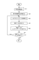
次に、本実施形態である表示装置1が表示部70の画質を校正する動作について説明する。図2は、表示装置1の表示部70の画質の校正処理の手順を表すフローチャートである。約1000時間の使用期間が経過した表示装置1について、この校正処理は実行される。画質特性検出部10が、その受光部側を表示部70の表示面に対向させて設けられた状態で、表示装置1は、同図のフローチャートによる処理を実行する。
Next, an operation in which the display device 1 according to the present embodiment calibrates the image quality of the
まず、ステップS1において、OSDメニューが表示部70に表示され、カーソルが画質校正処理開始タブを示した状態で、操作部80の設定値変更用ボタンが押されたことにより設定値変更用ボタンのキーコードが制御部90に供給されると、制御部90は、表示部70の画質の校正処理を開始する。
First, in step S1, the OSD menu is displayed on the
次に、ステップS2において、制御部90は、ルックアップテーブル60の非補正データを読み出し可能に制御し、ルックアップテーブル60から非補正映像信号を出力させる。次に、制御部90は、画質特性検出部10に補正前画質特性値の検出を指示する。次に、制御部90は、画質特性検出部10が検出した補正前画質特性値を補正前画質特性記憶部20に記憶させる。例えば、制御部90は、画質特性検出部10が検出した非画質補正画像における輝度対階調データを補正前画質特性記憶部20に記憶させる。
Next, in step S <b> 2, the
次に、ステップS3において、目標画質特性取得部40は、制御部90の制御によって目標画質特性記憶部30に記憶された複数種類の目標画質特性値の中から一種類の目標画質特性値を選択して読み込み保持する。例えば、目標画質特性取得部40は、制御部90の制御によって目標画質特性記憶部30に記憶された輝度対階調データを含むプロファイルデータ31a,31b,31cからプロファイルデータ31aを読み込んで保持する。
Next, in step S3, the target image quality
次に、ステップS4において、補正データ生成部50は、補正前画質特性記憶部20から補正前画質特性値を読み込み、目標画質特性取得部40から目標画質特性値を取り込む。次に、補正データ生成部50は、読み込んだ補正前画質特性値と取り込んだ目標画質特性値とに基づいて補正データを生成する。例えば、補正データ生成部50は、補正前画質特性記憶部20から補正前画質特性値である輝度対階調データを読み込み、目標画質特性取得部40から輝度対階調データを含むプロファイルデータ31aを取り込む。次に、補正データ生成部50は、読み込んだ輝度対階調データと取り込んだプロファイルデータ31aとに基づいて、印刷プレビューに適した画質特性に補正するための第1の補正データを生成する。
Next, in step S <b> 4, the correction
ここで、補正データ生成部50が補正前画質特性値と目標画質特性値とに基づいて補正データを生成する具体例について説明する。
図3は、輝度対階調データをグラフ化した図である。同図に示すグラフは4象限図であり、そのうちの第1象限が目標画質特性を表し、第2象限が補正前画質特性を表し、第3象限がルックアップテーブル60による補正画質特性を表す。第1象限の目標画質特性は、横軸が表示装置の入力階調であり、縦軸が表示部の輝度である。第2象限の補正前画質特性は、横軸が表示部の入力階調であり、縦軸が表示部の輝度である。第3象限の補正画質特性は、縦軸が補正LUT(ルックアップテーブル)入力階調であり、横軸が補正LUT出力階調である。Here, a specific example in which the correction
FIG. 3 is a graph of luminance versus gradation data. The graph shown in the figure is a quadrant diagram, in which the first quadrant represents the target image quality characteristic, the second quadrant represents the pre-correction image quality characteristic, and the third quadrant represents the corrected image quality characteristic by the lookup table 60. In the target image quality characteristics in the first quadrant, the horizontal axis represents the input gradation of the display device, and the vertical axis represents the luminance of the display unit. In the image quality characteristics before correction in the second quadrant, the horizontal axis represents the input gradation of the display unit, and the vertical axis represents the luminance of the display unit. In the corrected image quality characteristic of the third quadrant, the vertical axis is the correction LUT (lookup table) input gradation, and the horizontal axis is the correction LUT output gradation.
まず、手順Aとして、補正データ生成部50は、第1象限において表示装置入力階調値xを選択し、その表示装置入力階調値xに対応する目標輝度値yを求める。
次に、手順Bとして、補正データ生成部50は、第2象限を適用して、目標輝度yに対応する表示部入力階調値x’(シングルクォーテーション)を求める。
次に、手順Cとして、補正データ生成部50は、表示装置入力階調値xを補正LUT入力階調値xとし、この補正LUT入力階調値xと表示部入力階調値x’(シングルクォーテーション)との交点を補正データとして決定する。
補正データ生成部50は、上記手順Aから手順Cまでを全ての階調に対して繰り返し実行することによって、第3象限に示す補正画質特性を得ることができ、この第3象限の補正画質特性値をルックアップテーブル60に設定する補正データとする。First, as procedure A, the correction
Next, as the procedure B, the correction
Next, as the procedure C, the correction
The correction
次に、ステップS5において、補正データ生成部50は、ステップS4の処理において生成した補正データをルックアップテーブル60に書き込む。例えば、補正データ生成部50は、生成した第1の補正データをルックアップテーブル60に書き込む。
Next, in step S5, the correction
次に、ステップS6において、制御部90は、目標画質特性記憶部30に他の目標画質特性値が記憶されているか否かを判定する。そして、制御部90は、目標画質特性記憶部30に他の目標画質特性値が記憶されていると判定した場合は、ステップS3の処理に戻る。一方、制御部90は、目標画質特性記憶部30に他の目標画質特性値が記憶されていないと判定した場合は、本フローチャートの処理を終了する。
Next, in step S <b> 6, the
2回目のステップS3において、目標画質特性取得部40は、制御部90の制御によって目標画質特性記憶部30に記憶された残りの種類の目標画質特性値の中から一種類の目標画質特性値を選択して読み込み保持する。例えば、目標画質特性取得部40は、制御部90の制御によって目標画質特性記憶部30に記憶された輝度対階調データを含む残りのプロファイルデータ31b,31cからプロファイルデータ31bを読み込んで保持する。
In the second step S3, the target image quality
次に、2回目のステップS4において、補正データ生成部50は、目標画質特性取得部40から目標画質特性値を取り込む。次に、補正データ生成部50は、ステップS2の処理において既に読み込んである補正前画質特性値と本ステップS4において取り込んだ目標画質特性値とに基づいて補正データを生成する。例えば、補正データ生成部50は、目標画質特性取得部40から輝度対階調データを含むプロファイルデータ31bを取り込む。次に、補正データ生成部50は、既に読み込んである輝度対階調データと取り込んだプロファイルデータ31bとに基づいて、ビデオカメラによる撮影映像の表示に適した画質特性に補正するための第2の補正データを生成する。
Next, in the second step S <b> 4, the correction
次に、2回目のステップS5において、補正データ生成部50は、2回目のステップS4の処理において生成した補正データを、ルックアップテーブル60の前回の書き込み領域とは異なる領域に書き込む。例えば、補正データ生成部50は、生成した第2の補正データをルックアップテーブル60の第1の補正データの記憶領域とは異なる領域に書き込む。
Next, in the second step S <b> 5, the correction
3回目以降のステップS3−S5の処理については、2回目のステップS3−S5の処理と同様であるため、その説明を省略する。 Since the process of step S3-S5 after the 3rd time is the same as the process of step S3-S5 of the 2nd time, the description is abbreviate | omitted.
本発明の一実施形態によれば、例えば1000時間等の使用期間が経過するごとに一回の画質校正処理を実行することにより、表示装置1は、画質特性検出部10が検出した補正前画質特性値と目標画質特性記憶部30に記憶された全ての目標画質特性値とに基づいて、ルックアップテーブル60に設定された全てのプロファイルに対応する補正データを更新することができる。
よって、本実施形態である表示装置1によれば、長期間の使用に伴って変化した表示部70の画質を、簡単な操作によって全てのプロファイルに対応して補正することができる。According to an embodiment of the present invention, the display device 1 performs the pre-correction image quality detected by the image quality
Therefore, according to the display device 1 of the present embodiment, the image quality of the
なお、上述した実施形態である表示装置の一部の機能をコンピュータで実現するようにしてもよい。この場合、その機能を実現するためのプログラムをコンピュータ読み取り可能な記録媒体に記録して、この記録媒体に記録されたプログラムをコンピュータシステムに読み込ませ、実行することによって実現してもよい。なお、ここでいう「コンピュータシステム」とは、OS(Operating System)や周辺装置のハードウェアを含むものである。また、「コンピュータ読み取り可能な記録媒体」とは、フレキシブルディスク、光磁気ディスク、光ディスク、メモリカード等の可搬型記録媒体、コンピュータシステムに内蔵される磁気ハードディスク等の記憶装置のことをいう。さらに「コンピュータ読み取り可能な記録媒体」とは、インターネット等のネットワークや電話回線等の通信回線を介してプログラムを送信する場合の通信線のように、短時間の間、動的にプログラムを保持するもの、その場合のサーバ装置やクライアントとなるコンピュータシステム内部の揮発性メモリのように、一定時間プログラムを保持するものを含んでもよい。また上記のプログラムは、前述した機能の一部を実現するためのものであってもよく、さらに前述した機能をコンピュータシステムにすでに記録されているプログラムとの組み合わせにより実現するものであってもよい。 In addition, you may make it implement | achieve a part of function of the display apparatus which is embodiment mentioned above with a computer. In this case, a program for realizing the function may be recorded on a computer-readable recording medium, and the program recorded on the recording medium may be read into a computer system and executed. Here, the “computer system” includes an OS (Operating System) and peripheral device hardware. The “computer-readable recording medium” refers to a portable recording medium such as a flexible disk, a magneto-optical disk, an optical disk, and a memory card, and a storage device such as a magnetic hard disk built in the computer system. Furthermore, the “computer-readable recording medium” dynamically holds a program for a short time like a communication line when transmitting a program via a network such as the Internet or a communication line such as a telephone line. In this case, it may include a device that holds a program for a certain period of time, such as a volatile memory inside a computer system serving as a server device or a client. Further, the above program may be for realizing a part of the functions described above, or may be realized by a combination with the program already recorded in the computer system. .
以上、本発明の実施の形態について図面を参照して詳述したが、具体的な構成はその実施形態に限られるものではなく、本発明の要旨を逸脱しない範囲の設計等も含まれる。
例えば、図2の校正手順では補正データの作成を行わず、補正前画質特性値の記憶だけを行うことが考えられる。この場合は、後日、特定のプロファイルデータが指定された時点で補正データを計算する。指定された時点とは、例えば、電源投入時やユーザによる画質設定変更時である。補正データを記憶するルックアップテーブルは、現在表示されているプロファイルデータの容量だけを有すればよい。このため、プロファイルデータの数が多くなった場合の、ルックアップテーブル数や計算時間等、実装コストを削減することができる。As mentioned above, although embodiment of this invention was explained in full detail with reference to drawings, the specific structure is not restricted to that embodiment, The design of the range which does not deviate from the summary of this invention, etc. are included.
For example, in the calibration procedure of FIG. 2, it is conceivable that correction data is not created but only the image quality characteristic value before correction is stored. In this case, correction data is calculated later when specific profile data is designated. The designated time is, for example, when the power is turned on or when the image quality setting is changed by the user. The lookup table that stores the correction data need only have the capacity of the currently displayed profile data. For this reason, when the number of profile data increases, the mounting cost such as the number of lookup tables and the calculation time can be reduced.
本発明は、表示装置、例えば、表示パネルを含む直視型の表示装置、CRTを含む表示装置、投射型投影装置であるプロジェクタに利用可能である。 The present invention is applicable to a display device, for example, a direct-view display device including a display panel, a display device including a CRT, and a projector that is a projection type projection device.
1 表示装置
10 画質特性検出部
20 補正前画質特性記憶部
30 目標画質特性記憶部
31a,31b,31c プロファイルデータ
40 目標画質特性取得部
50 補正データ生成部
60 ルックアップテーブル
70 表示部
80 操作部
90 制御部DESCRIPTION OF SYMBOLS 1
Claims (6)
前記映像信号を補正した補正映像信号を出力する映像信号補正部と、
所定の使用期間が経過したときにメニューを表示し、前記メニューを通じて校正処理の開始が入力された場合、前記映像信号に基づいて非画質補正画像を表示し、前記補正映像信号に基づいて補正画像を表示する表示部と、
前記非画質補正画像に基づいて補正前画質特性値を取得する補正前画質特性取得部と、
少なくとも第1の目標画質特性値および第2の目標画質特性値を記憶する目標画質特性記憶部と、
前記補正前画質特性値と前記第1の目標画質特性値とに基づいて第1の補正データを生成し、前記第1の補正データを前記映像信号補正部の記憶領域に書き込み、前記目標画質特性記憶部の記憶領域に前記第2の目標画質特性値が記憶されている場合、前記補正前画質特性値と前記第2の目標画質特性値とに基づいて第2の補正データを生成し、前記第2の補正データを前記映像信号補正部の記憶領域に書き込み、前記目標画質特性記憶部の記憶領域に前記第2の目標画質特性値が記憶されていない場合、前記映像信号の補正データの生成を終了する補正データ生成部と、を備え、
前記映像信号補正部は、前記補正データ生成部によって前記映像信号補正部の記憶領域に書き込まれた前記第1の補正データまたは前記第2の補正データに基づいて前記映像信号を補正する
ことを特徴とする表示装置。 A display device that receives a video signal and displays an image,
A video signal correction unit that outputs a corrected video signal obtained by correcting the video signal;
When a predetermined use period has elapsed, a menu is displayed, and when the start of calibration processing is input through the menu, a non-quality corrected image is displayed based on the video signal, and a corrected image is displayed based on the corrected video signal A display unit for displaying,
A pre-correction image quality characteristic acquisition unit for acquiring a pre-correction image quality characteristic value based on the non-image quality corrected image;
A target image quality characteristic storage unit for storing at least a first target image quality characteristic value and a second target image quality characteristic value;
First correction data is generated based on the pre-correction image quality characteristic value and the first target image quality characteristic value, and the first correction data is written in a storage area of the video signal correction unit, and the target image quality characteristic When the second target image quality characteristic value is stored in the storage area of the storage unit, second correction data is generated based on the pre-correction image quality characteristic value and the second target image quality characteristic value, When the second correction data is written in the storage area of the video signal correction unit, and the second target image quality characteristic value is not stored in the storage area of the target image quality characteristic storage unit, generation of correction data of the video signal is generated A correction data generation unit for ending
The video signal correction unit corrects the video signal based on the first correction data or the second correction data written in the storage area of the video signal correction unit by the correction data generation unit. Display device.
前記第1の補正データは、前記第1の目標画質特性値が取得された時に生成され、前記第2の補正データは、前記第2の目標画質特性値が取得された時に生成される
ことを特徴とする請求項1記載の表示装置。 A target image quality characteristic acquisition unit that selects and acquires the first target image quality characteristic value or the second target image quality characteristic value from the target image quality characteristic storage unit;
The first correction data is generated when the first target image quality characteristic value is acquired, and the second correction data is generated when the second target image quality characteristic value is acquired. The display device according to claim 1, characterized in that:
前記第1の目標画質特性値および前記第2の目標画質特性値はいずれも、目標画質に対応する輝度対階調データである
ことを特徴とする請求項1または2記載の表示装置。 The pre-correction image quality characteristic value is luminance versus gradation data of the non-image quality corrected image,
The display device according to claim 1, wherein each of the first target image quality characteristic value and the second target image quality characteristic value is luminance versus gradation data corresponding to the target image quality.
前記補正データ生成部は、さらに、前記目標画質特性記憶部の記憶領域に前記第3の目標画質特性値が記憶されている場合、前記補正前画質特性値と前記第3の目標画質特性値とに基づいて、前記映像信号の画質特性をテキスト表示に適した画質特性に補正するための第3の補正データを生成し、該第3の補正データを前記映像信号補正部の記憶領域に書き込み、前記目標画質特性記憶部の記憶領域に前記第3の目標画質特性値が記憶されていない場合、前記映像信号の補正データの生成を終了し、
前記映像信号補正部は、前記第1の補正データ、前記第2の補正データ、前記第3の補正データのいずれか1つの補正データに基づいて前記映像信号を補正する
ことを特徴とする請求項1記載の表示装置。 The target image quality characteristic storage unit further stores a third target image quality characteristic value,
When the third target image quality characteristic value is stored in the storage area of the target image quality characteristic storage unit, the correction data generation unit further includes the pre-correction image quality characteristic value and the third target image quality characteristic value. And generating third correction data for correcting the image quality characteristic of the video signal to an image quality characteristic suitable for text display, and writing the third correction data to the storage area of the video signal correction unit, If the third target image quality characteristic value is not stored in the storage area of the target image quality characteristic storage unit, the generation of the correction data of the video signal is terminated,
The video signal correction unit corrects the video signal based on correction data of any one of the first correction data, the second correction data, and the third correction data. The display device according to 1.
ことを特徴とする請求項1または2記載の表示装置。 The display device according to claim 1, wherein the first correction data or the second correction data is generated when the power is turned on or the image quality setting is changed.
所定の使用期間が経過したときにメニューを表示し、前記メニューを通じて校正処理の開始が入力された場合、前記映像信号に基づいて非画質補正画像を表示するステップと、
前記非画質補正画像に基づいて補正前画質特性値を取得するステップと、
少なくとも第1の目標画質特性値および第2の目標画質特性値を目標画質特性記憶部に記憶するステップと、
前記補正前画質特性値と前記第1の目標画質特性値とに基づいて第1の補正データを生成し、前記第1の補正データを、前記映像信号を補正した補正映像信号を出力する映像信号補正部の記憶領域に書き込み、前記目標画質特性記憶部の記憶領域に前記第2の目標画質特性値が記憶されている場合、前記補正前画質特性値と前記第2の目標画質特性値とに基づいて第2の補正データを生成し、前記第2の補正データを前記映像信号補正部の記憶領域に書き込み、前記目標画質特性記憶部の記憶領域に前記第2の目標画質特性値が記憶されていない場合、前記映像信号の補正データの生成を終了するステップと、
前記映像信号補正部が、前記映像信号補正部の記憶領域に書き込まれた前記第1の補正データまたは前記第2の補正データに基づいて前記映像信号を補正するステップと、
を有することを特徴とする表示装置の校正方法。 Receiving a video signal;
Displaying a menu when a predetermined period of use has elapsed, and displaying a non-quality-corrected image based on the video signal when a calibration process start is input through the menu; and
Obtaining a pre-correction image quality characteristic value based on the non-image quality corrected image;
Storing at least the first target image quality characteristic value and the second target image quality characteristic value in the target image quality characteristic storage unit ;
A video signal that generates first correction data based on the pre-correction image quality characteristic value and the first target image quality characteristic value, and outputs the corrected video signal obtained by correcting the video signal using the first correction data. When writing to the storage area of the correction unit and the second target image quality characteristic value is stored in the storage area of the target image quality characteristic storage unit, the pre-correction image quality characteristic value and the second target image quality characteristic value are Second correction data is generated based on the second correction data, the second correction data is written in the storage area of the video signal correction unit, and the second target image quality characteristic value is stored in the storage area of the target image quality characteristic storage unit. If not, the step of ending the generation of the correction data of the video signal;
The video signal correction unit correcting the video signal based on the first correction data or the second correction data written in a storage area of the video signal correction unit ;
A method for calibrating a display device, comprising:
Applications Claiming Priority (1)
| Application Number | Priority Date | Filing Date | Title |
|---|---|---|---|
| PCT/JP2010/071400 WO2012073341A1 (en) | 2010-11-30 | 2010-11-30 | Display device and correction method for display device |
Publications (2)
| Publication Number | Publication Date |
|---|---|
| JPWO2012073341A1 JPWO2012073341A1 (en) | 2014-05-19 |
| JP5773453B2 true JP5773453B2 (en) | 2015-09-02 |
Family
ID=46171327
Family Applications (1)
| Application Number | Title | Priority Date | Filing Date |
|---|---|---|---|
| JP2012546618A Active JP5773453B2 (en) | 2010-11-30 | 2010-11-30 | Display device and calibration method for display device |
Country Status (2)
| Country | Link |
|---|---|
| JP (1) | JP5773453B2 (en) |
| WO (1) | WO2012073341A1 (en) |
Citations (5)
| Publication number | Priority date | Publication date | Assignee | Title |
|---|---|---|---|---|
| JP2000276094A (en) * | 1999-03-29 | 2000-10-06 | Fuji Photo Film Co Ltd | Gradation correction method and image display system |
| JP2003288057A (en) * | 2002-03-28 | 2003-10-10 | Fuji Photo Film Co Ltd | Liquid crystal display device |
| JP2003295851A (en) * | 2002-03-29 | 2003-10-15 | Fuji Photo Film Co Ltd | Image display device |
| JP2006310943A (en) * | 2005-04-26 | 2006-11-09 | Nec Electronics Corp | Display control unit and generating method of lookup table |
| JP2008166892A (en) * | 2006-12-27 | 2008-07-17 | Sony Corp | Data processing apparatus, image signal processing apparatus and method, and computer program |
Family Cites Families (1)
| Publication number | Priority date | Publication date | Assignee | Title |
|---|---|---|---|---|
| JP4393433B2 (en) * | 2005-07-29 | 2010-01-06 | 株式会社ナナオ | Liquid crystal display device, luminance measurement method, and computer program |
-
2010
- 2010-11-30 JP JP2012546618A patent/JP5773453B2/en active Active
- 2010-11-30 WO PCT/JP2010/071400 patent/WO2012073341A1/en not_active Ceased
Patent Citations (5)
| Publication number | Priority date | Publication date | Assignee | Title |
|---|---|---|---|---|
| JP2000276094A (en) * | 1999-03-29 | 2000-10-06 | Fuji Photo Film Co Ltd | Gradation correction method and image display system |
| JP2003288057A (en) * | 2002-03-28 | 2003-10-10 | Fuji Photo Film Co Ltd | Liquid crystal display device |
| JP2003295851A (en) * | 2002-03-29 | 2003-10-15 | Fuji Photo Film Co Ltd | Image display device |
| JP2006310943A (en) * | 2005-04-26 | 2006-11-09 | Nec Electronics Corp | Display control unit and generating method of lookup table |
| JP2008166892A (en) * | 2006-12-27 | 2008-07-17 | Sony Corp | Data processing apparatus, image signal processing apparatus and method, and computer program |
Also Published As
| Publication number | Publication date |
|---|---|
| WO2012073341A1 (en) | 2012-06-07 |
| JPWO2012073341A1 (en) | 2014-05-19 |
Similar Documents
| Publication | Publication Date | Title |
|---|---|---|
| US7986355B2 (en) | Picture displaying method, picture displaying apparatus, and imaging apparatus | |
| JP4605987B2 (en) | Projector, image processing method, and information storage medium | |
| JP3775666B2 (en) | Image display device | |
| TWI423655B (en) | Image processing device, image processing method, display device, and projection display device | |
| JPWO2002019307A1 (en) | Environmentally adaptive image display system, image processing method, and information storage medium | |
| JP2003050572A (en) | Image display system, projector, program, information storage medium, and image processing method | |
| CN100477733C (en) | Display apparatus | |
| JP5962428B2 (en) | Image processing apparatus adjustment method, adjustment apparatus, image processing apparatus, and display module | |
| JP4824206B2 (en) | Display data processing circuit and liquid crystal display device | |
| US8514333B2 (en) | Image display device for displaying color image on color display unit | |
| US8514334B2 (en) | Image display device for displaying color image on color display unit | |
| JP2015231140A (en) | Image processing apparatus, image processing method, and program | |
| JP4698155B2 (en) | Method for adjusting display characteristics of display device | |
| JP4259046B2 (en) | Image display device and image processing device | |
| JP2020067629A (en) | Image processing device and image processing method | |
| JP5773453B2 (en) | Display device and calibration method for display device | |
| KR102530018B1 (en) | Device and method for controlling color gamut | |
| JP2004102244A (en) | Liquid crystal display | |
| JP2005260405A (en) | Image processing apparatus and image processing method | |
| JP2011158804A (en) | Image display apparatus and method of controlling the same | |
| JP2006284971A (en) | Burn-in phenomenon correction method, self-luminous device, burn-in phenomenon correction apparatus, and program | |
| JP2010117818A (en) | Image processor and image processing program | |
| JP2016149047A (en) | Image processing apparatus, display device, and image processing method | |
| JP2008139709A (en) | Color processing apparatus and method | |
| JP2002140060A (en) | Image display system |
Legal Events
| Date | Code | Title | Description |
|---|---|---|---|
| A131 | Notification of reasons for refusal |
Free format text: JAPANESE INTERMEDIATE CODE: A131 Effective date: 20140304 |
|
| A521 | Request for written amendment filed |
Free format text: JAPANESE INTERMEDIATE CODE: A523 Effective date: 20140507 |
|
| A02 | Decision of refusal |
Free format text: JAPANESE INTERMEDIATE CODE: A02 Effective date: 20141125 |
|
| A521 | Request for written amendment filed |
Free format text: JAPANESE INTERMEDIATE CODE: A523 Effective date: 20150129 |
|
| A911 | Transfer to examiner for re-examination before appeal (zenchi) |
Free format text: JAPANESE INTERMEDIATE CODE: A911 Effective date: 20150210 |
|
| A131 | Notification of reasons for refusal |
Free format text: JAPANESE INTERMEDIATE CODE: A131 Effective date: 20150310 |
|
| A521 | Request for written amendment filed |
Free format text: JAPANESE INTERMEDIATE CODE: A523 Effective date: 20150415 |
|
| TRDD | Decision of grant or rejection written | ||
| A01 | Written decision to grant a patent or to grant a registration (utility model) |
Free format text: JAPANESE INTERMEDIATE CODE: A01 Effective date: 20150602 |
|
| A61 | First payment of annual fees (during grant procedure) |
Free format text: JAPANESE INTERMEDIATE CODE: A61 Effective date: 20150625 |
|
| R150 | Certificate of patent or registration of utility model |
Ref document number: 5773453 Country of ref document: JP Free format text: JAPANESE INTERMEDIATE CODE: R150 |
|
| S533 | Written request for registration of change of name |
Free format text: JAPANESE INTERMEDIATE CODE: R313533 |
|
| R350 | Written notification of registration of transfer |
Free format text: JAPANESE INTERMEDIATE CODE: R350 |