JP5774449B2 - 制御電流源を備える電力変換装置 - Google Patents
制御電流源を備える電力変換装置 Download PDFInfo
- Publication number
- JP5774449B2 JP5774449B2 JP2011242023A JP2011242023A JP5774449B2 JP 5774449 B2 JP5774449 B2 JP 5774449B2 JP 2011242023 A JP2011242023 A JP 2011242023A JP 2011242023 A JP2011242023 A JP 2011242023A JP 5774449 B2 JP5774449 B2 JP 5774449B2
- Authority
- JP
- Japan
- Prior art keywords
- bus
- voltage
- current
- power
- rectifier
- Prior art date
- Legal status (The legal status is an assumption and is not a legal conclusion. Google has not performed a legal analysis and makes no representation as to the accuracy of the status listed.)
- Expired - Fee Related
Links
- 238000006243 chemical reaction Methods 0.000 title claims description 26
- 239000003990 capacitor Substances 0.000 claims description 19
- 238000011144 upstream manufacturing Methods 0.000 claims description 5
- 230000001360 synchronised effect Effects 0.000 claims description 4
- 230000002457 bidirectional effect Effects 0.000 description 2
- 230000002427 irreversible effect Effects 0.000 description 2
- 238000000034 method Methods 0.000 description 2
- 230000002441 reversible effect Effects 0.000 description 2
- 230000003466 anti-cipated effect Effects 0.000 description 1
- 238000012986 modification Methods 0.000 description 1
- 230000004048 modification Effects 0.000 description 1
- 230000008929 regeneration Effects 0.000 description 1
- 238000011069 regeneration method Methods 0.000 description 1
Images




Classifications
-
- H—ELECTRICITY
- H02—GENERATION; CONVERSION OR DISTRIBUTION OF ELECTRIC POWER
- H02M—APPARATUS FOR CONVERSION BETWEEN AC AND AC, BETWEEN AC AND DC, OR BETWEEN DC AND DC, AND FOR USE WITH MAINS OR SIMILAR POWER SUPPLY SYSTEMS; CONVERSION OF DC OR AC INPUT POWER INTO SURGE OUTPUT POWER; CONTROL OR REGULATION THEREOF
- H02M7/00—Conversion of AC power input into DC power output; Conversion of DC power input into AC power output
- H02M7/02—Conversion of AC power input into DC power output without possibility of reversal
- H02M7/04—Conversion of AC power input into DC power output without possibility of reversal by static converters
- H02M7/12—Conversion of AC power input into DC power output without possibility of reversal by static converters using discharge tubes with control electrode or semiconductor devices with control electrode
- H02M7/21—Conversion of AC power input into DC power output without possibility of reversal by static converters using discharge tubes with control electrode or semiconductor devices with control electrode using devices of a triode or transistor type requiring continuous application of a control signal
- H02M7/217—Conversion of AC power input into DC power output without possibility of reversal by static converters using discharge tubes with control electrode or semiconductor devices with control electrode using devices of a triode or transistor type requiring continuous application of a control signal using semiconductor devices only
- H02M7/2176—Conversion of AC power input into DC power output without possibility of reversal by static converters using discharge tubes with control electrode or semiconductor devices with control electrode using devices of a triode or transistor type requiring continuous application of a control signal using semiconductor devices only comprising a passive stage to generate a rectified sinusoidal voltage and a controlled switching element in series between such stage and the output
-
- H—ELECTRICITY
- H02—GENERATION; CONVERSION OR DISTRIBUTION OF ELECTRIC POWER
- H02M—APPARATUS FOR CONVERSION BETWEEN AC AND AC, BETWEEN AC AND DC, OR BETWEEN DC AND DC, AND FOR USE WITH MAINS OR SIMILAR POWER SUPPLY SYSTEMS; CONVERSION OF DC OR AC INPUT POWER INTO SURGE OUTPUT POWER; CONTROL OR REGULATION THEREOF
- H02M1/00—Details of apparatus for conversion
- H02M1/12—Arrangements for reducing harmonics from AC input or output
Landscapes
- Engineering & Computer Science (AREA)
- Power Engineering (AREA)
- Rectifiers (AREA)
- Dc-Dc Converters (AREA)
Description
− THDiは、基本波電流の48%より少なければならない、
− PWHDは、基本波電流の46%より少なければならない、
− 次数5の高調波は、基本波電流の40%までに限定されなければならない、
− 次数7の高調波は、基本波電流の25%までに限定されなければならない、
− 次数11の高調波は、基本波電流の15%までに限定されなければならない、
− 次数13の高調波は、基本波電流の10%までに限定されなければならない。
決定された基本周波数(determined fundamental frequency)で入力電流を供給する回路網の複数の相に接続され、整流器電圧が印加される、整流器ステージと、
前記整流器ステージに接続されたDC電源バスであって、前記DC電源バス上で電圧を得るために電位が各々に印加される第1の電源ラインおよび第2の電源ラインを備える、DC電源バスと、
第1の電源ラインおよび第2の電源ラインに接続されたバス・キャパシタと、
を備える電力変換装置であって、
前記電力変換装置は、
前記第1の電源ラインまたは前記第2の電源ライン上で、バス・キャパシタの上流に位置する制御電流源であって、前記制御電流源は、インダクタおよび可変電圧源を備える、制御電流源と、
前記制御電流源用の制御手段であって、前記制御手段は、整流器電流と称され、前記DC電源バス上を流れる電流を制御するために、決定された電圧を前記可変電圧源の端子間に印加するように構成され、前記電圧は、整流器電圧と、前記DC電源バス上の電圧と、電流高調波とに基づいて決定され、前記電流高調波は、前記回路網から供給された前記入力電流の前記基本周波数の6倍および12倍の周波数でそれぞれ同期化された第1の高調波および第2の高調波を含み、これらの高調波の振幅および位相が、THDiおよびPWHDを限定(limit)するように決定される、制御手段と、を備えることを特徴とする電力変換装置によって達成される。
− 低い値のインダクタLと、
− はっきりと異なる2つの並列な切り替えアームと、これら2つの切り替えアームと並列に接続されたキャパシタC1とから成る電子変換装置2、の形を取る制御可変電圧源(controlled variable voltage source)とを含む。
VL=Vred−Vbus−Vaux
− 電子変換装置2のキャパシタC1の端子間の電圧VCの値を測定する、
− 入力として印加された基準値Vc refと、電子変換装置2のキャパシタC1の端子間の電圧について測定された値VCとを比較して差D1を決定する、
− 前記差D1を、例えば比例、積分、および微分(PID(Proportional-Integral-Derivative))調整器などの調整器に導入して、平均整流器電流の基準値<Ired>refを決定する、
− 平均整流器電流の基準値<Ired>ref上に高調波Ishを投入し、前記高調波Ishは、変換装置への入力として回路網から供給された入力電流Ieの基本周波数Fmainsの6*k倍の周波数で同期化され、kは1以上の整数であり、kは追加の各高調波ごとに1単位分増加され、それによって整流器電流用の基準値Ired refを生成する、
− 整流器電流用に得られた基準値Ired refと測定された整流器電流Iredを比較して、差D2を決定する、
− 前記差D2を、例えば比例(P(Proportional))調整器などの調整器に導入して、制御電流源のインダクタLの端子間の電圧用の基準値VL refを決定する、
− インダクタLの端子間の電圧の基準値VL refと、整流器電圧Vredの測定値と、DC電源バスの電圧Vbusの測定値とに基づき、電子変換装置2の端子間の電圧用の基準値Vaux refを決定する。

Ie 入力電流
Ired 整流器電流
V+ 正電位
V− 負電位
VL、Vred、Vbus、Vaux、VC 電圧
L インダクタ
D1、D2 ダイオード
T1、T2 電子スイッチ
Cbus バス・キャパシタ
M1,M2、M3 中間点
P1、P2 接続中間点
D1、D2 差
<Ired>ref、Ired ref、VCref、VL ref、Vaux ref 基準値
Ish 高調波
Vbus ref 軌跡
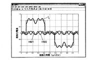
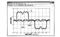
HM1、HM2、HM3、HM4、HM5 高調波
Claims (7)
- 決定された基本周波数(Fmains)で入力電流(Ie)を供給する回路網の複数の相(R、S、T)に接続され、整流器電圧が印加される、整流器ステージ(1)と、
前記整流器ステージ(1)に接続されたDC電源バスであって、前記DC電源バス上で電圧(Vbus)を得るために電位が各々に印加される第1の電源ライン(V+)および第2の電源ライン(V−)を備える、DC電源バスと、
前記第1の電源ラインおよび前記第2の電源ラインに接続されたバス・キャパシタ(Cbus)と、
を備える電力変換装置であって、
前記電力変換装置は、
前記第1の電源ラインまたは前記第2の電源ライン上で、前記バス・キャパシタ(Cbus)の上流に位置する制御電流源であって、前記制御電流源は、インダクタ(L)および可変電圧源を備える、制御電流源と、
前記制御電流源用の制御手段(3)であって、前記制御手段は、整流器電流(Ired)と称され、前記DC電源バス上を流れる電流を制御するために、決定された電圧(Vaux)を前記可変電圧源の端子間に印加するように構成され、前記電圧(Vaux)は、整流器電圧(Vred)と、前記DC電源バス上の電圧(Vbus)と、電流高調波とに基づいて決定され、前記電流高調波は、前記回路網から供給された前記入力電流(Ie)の前記基本周波数(Fmains)の6倍および12倍の周波数でそれぞれ同期化された第1の高調波および第2の高調波を含み、これらの高調波の振幅および位相が、THDiおよびPWHDを限定するように決定される、制御手段(3)と、
を備え、
前記可変電圧源は、並列に接続された第1の切り替えアーム、第2の切り替えアーム、およびキャパシタ(C1)を備える電子変換装置(2)を備え、各切り替えアームは、少なくとも1つの電子スイッチ(T1、T2)を備え、
前記制御手段(3)は、調整ループを実行するように構成されており、前記調整ループは、前記整流器電流(I red )を、前記高調波が投入される平均基準値(<I red > ref )に等しい基準値(I red ref )に追従させるように設計されており、
前記平均基準値(<I red > ref )は、基準値(V C ref )と、前記電子変換装置の前記キャパシタ(C1)の端子間の電圧について測定された値(V C )との間の差が導入される調整器の出力にて得られる、
ことを特徴とする電力変換装置。 - 前記制御手段(3)は、調整ループを実行するように構成されており、前記調整ループは、前記DC電源バス上の前記電圧(Vbus)を、前記高調波を含む基準値(Vbus ref)に追従させるように設計されていることを特徴とする、請求項1に記載の変換装置。
- 前記調整ループは、前記可変電圧源の端子間の前記電圧用の基準値(Vaux ref)を決定するように意図されていることを特徴とする、請求項1または2に記載の変換装置。
- 前記第1の高調波は、前記整流器電流の10%から30%の範囲にある振幅を示すことを特徴とする、請求項1乃至3のいずれか1項に記載の変換装置。
- 前記第2の高調波は、前記整流器電流の0%から15%の範囲にある振幅を示すことを特徴とする、請求項1乃至4のいずれか1項に記載の変換装置。
- 前記第1の高調波(HM1)と前記第2の高調波(HM2)は、最初に逆位相で投入されることを特徴とする、請求項1乃至5のいずれか1項に記載の変換装置。
- 複数の切り替えアームが設けられたインバータステージを備え、前記複数の切り替えアームは、DC電圧を、電気的負荷に給電するよう意図された可変電圧に変換するように意図されている、可変速駆動装置であって、
前記可変速駆動装置は、請求項1乃至6のいずれか1項で定義された電力変換装置を備え、前記電力変換装置は、そのインバータステージの上流に接続されていることを特徴とする、可変速駆動装置。
Applications Claiming Priority (2)
| Application Number | Priority Date | Filing Date | Title |
|---|---|---|---|
| FR1059116 | 2010-11-05 | ||
| FR1059116A FR2967315B1 (fr) | 2010-11-05 | 2010-11-05 | Convertisseur de puissance a source de courant commandee |
Publications (2)
| Publication Number | Publication Date |
|---|---|
| JP2012105530A JP2012105530A (ja) | 2012-05-31 |
| JP5774449B2 true JP5774449B2 (ja) | 2015-09-09 |
Family
ID=44168339
Family Applications (1)
| Application Number | Title | Priority Date | Filing Date |
|---|---|---|---|
| JP2011242023A Expired - Fee Related JP5774449B2 (ja) | 2010-11-05 | 2011-11-04 | 制御電流源を備える電力変換装置 |
Country Status (6)
| Country | Link |
|---|---|
| US (1) | US8964425B2 (ja) |
| EP (1) | EP2461467B1 (ja) |
| JP (1) | JP5774449B2 (ja) |
| CN (1) | CN102570867B (ja) |
| ES (1) | ES2439073T3 (ja) |
| FR (1) | FR2967315B1 (ja) |
Families Citing this family (4)
| Publication number | Priority date | Publication date | Assignee | Title |
|---|---|---|---|---|
| FR2969418B1 (fr) | 2010-12-20 | 2012-12-14 | Schneider Toshiba Inverter | Convertisseur de puissance ac/dc a facteur de puissance et thdi ameliores |
| US20160262729A1 (en) * | 2015-03-11 | 2016-09-15 | Edan Instruments, Inc. | Systems and methods of reducing ultrasonic speckle using harmonic compounding |
| GB2551463A (en) * | 2016-02-03 | 2017-12-27 | Siemens Ag | Power converter and method for controlling a power converter |
| DE102019120682A1 (de) * | 2019-07-31 | 2021-02-04 | Ebm-Papst Mulfingen Gmbh & Co. Kg | Schaltung und Verfahren zur Reduktion netzseitiger Oberwellen im Eingangsstrom eines Diodengleichrichters |
Family Cites Families (11)
| Publication number | Priority date | Publication date | Assignee | Title |
|---|---|---|---|---|
| US5499178A (en) * | 1991-12-16 | 1996-03-12 | Regents Of The University Of Minnesota | System for reducing harmonics by harmonic current injection |
| JP3151932B2 (ja) * | 1992-04-27 | 2001-04-03 | ヤマハ株式会社 | 電源回路 |
| US5483140A (en) * | 1993-10-01 | 1996-01-09 | Wisconsin Alumni Research Foundation | Thyristor based DC link current source power conversion system for motor driven operation |
| US6839249B2 (en) * | 2001-01-10 | 2005-01-04 | Honeywell International Inc. | AC-to-ac power converter without a dc link capacitor |
| GB0325067D0 (en) * | 2003-10-27 | 2003-12-03 | Goodrich Actuation Systems Ltd | Multi-pulse converter circuits |
| JP2005204429A (ja) * | 2004-01-16 | 2005-07-28 | Toshiba Corp | 高周波抑制制御装置 |
| JP4370946B2 (ja) * | 2004-03-12 | 2009-11-25 | 富士電機ホールディングス株式会社 | 三相整流装置 |
| FR2893787B1 (fr) * | 2005-11-22 | 2007-12-21 | Schneider Toshiba Inverter | Dispositif de correction de facteur de puissance pour variateur de vitesse |
| EP1972056B1 (en) * | 2005-12-20 | 2009-12-23 | Crompton Greaves Limited | A dynamic harmonic filter for an ac power system |
| EP2034600B1 (en) * | 2007-09-05 | 2010-12-15 | ABB Oy | Single-phase to three-phase converter |
| FR2932329B1 (fr) | 2008-06-06 | 2010-05-14 | Schneider Toshiba Inverter | Dispositif de recuperation d'energie dans un variateur de vitesse |
-
2010
- 2010-11-05 FR FR1059116A patent/FR2967315B1/fr not_active Expired - Fee Related
-
2011
- 2011-10-14 EP EP11185159.8A patent/EP2461467B1/fr not_active Not-in-force
- 2011-10-14 ES ES11185159T patent/ES2439073T3/es active Active
- 2011-10-19 US US13/276,542 patent/US8964425B2/en not_active Expired - Fee Related
- 2011-11-04 JP JP2011242023A patent/JP5774449B2/ja not_active Expired - Fee Related
- 2011-11-07 CN CN201110347615.8A patent/CN102570867B/zh not_active Expired - Fee Related
Also Published As
| Publication number | Publication date |
|---|---|
| EP2461467B1 (fr) | 2013-11-13 |
| CN102570867B (zh) | 2015-11-18 |
| FR2967315A1 (fr) | 2012-05-11 |
| CN102570867A (zh) | 2012-07-11 |
| EP2461467A1 (fr) | 2012-06-06 |
| FR2967315B1 (fr) | 2012-11-16 |
| JP2012105530A (ja) | 2012-05-31 |
| ES2439073T3 (es) | 2014-01-21 |
| US8964425B2 (en) | 2015-02-24 |
| US20120113691A1 (en) | 2012-05-10 |
Similar Documents
| Publication | Publication Date | Title |
|---|---|---|
| KR102048031B1 (ko) | 유도 전력 전송 제어 | |
| US10819224B2 (en) | Power factor correction circuit, control method and controller | |
| CN107852089B (zh) | 蓄电池充电器 | |
| RU2521086C2 (ru) | Способ и устройство управления выходным сигналом, подлежащим достаке в нагрузку, и система бесперебойного питания | |
| JP5663502B2 (ja) | 力率改善デバイス | |
| EP2798731A2 (en) | A system, a method and a computer program product for controlling electric power supply | |
| CN107852007A (zh) | 蓄电池充电器 | |
| Bhat et al. | Three-phase, power quality improvement ac/dc converters | |
| US10381921B1 (en) | Soft-switching triangular current mode control for three phase two-level converters with power factor control | |
| JP5774449B2 (ja) | 制御電流源を備える電力変換装置 | |
| CN112928898A (zh) | 功率变换器的bus电压均衡调节方法及功率变换器 | |
| CN107852088A (zh) | 蓄电池充电器 | |
| Le et al. | Inductance-independent nonlinearity compensation for single-phase grid-tied inverter operating in both continuous and discontinuous current mode | |
| Jha et al. | Hardware implementation of single phase power factor correction system using micro-controller | |
| Kumar et al. | Design and Simulation of Interleaved Boost PFC Converter with PR Controller | |
| CN101814752A (zh) | Ups的控制系统和方法 | |
| Park et al. | Versatile unidirectional AC-DC converter with harmonic current and reactive power compensation for smart grid applications | |
| Li et al. | Bi-directional active-filter-integrated AC/DC converter without electrolytic capacitor and extra power switches | |
| Singh et al. | Performance analysis of AC-DC power converter using PWM techniques | |
| KR101883052B1 (ko) | 역률 보상 제어 장치 | |
| Ganacim et al. | Output power feedforward technique applied to a high power factor rectifier with high frequency transformer | |
| CN111864816B (zh) | 一种供电控制方法、装置、电子设备及存储介质 | |
| Zhao | Research Analysis of a Bidirectional AC-DC Converter for the Front-End of an On-Board Charger | |
| Chaturvedi et al. | SOGI-PLL-based control scheme for PFC Boost Converter under Distorted Grid Condition | |
| Khin et al. | Design and Simulation of Power Factor Correction Boost Converter using Hysteresis Control |
Legal Events
| Date | Code | Title | Description |
|---|---|---|---|
| A621 | Written request for application examination |
Free format text: JAPANESE INTERMEDIATE CODE: A621 Effective date: 20140526 |
|
| A977 | Report on retrieval |
Free format text: JAPANESE INTERMEDIATE CODE: A971007 Effective date: 20150212 |
|
| A131 | Notification of reasons for refusal |
Free format text: JAPANESE INTERMEDIATE CODE: A131 Effective date: 20150224 |
|
| A521 | Written amendment |
Free format text: JAPANESE INTERMEDIATE CODE: A523 Effective date: 20150514 |
|
| TRDD | Decision of grant or rejection written | ||
| A01 | Written decision to grant a patent or to grant a registration (utility model) |
Free format text: JAPANESE INTERMEDIATE CODE: A01 Effective date: 20150602 |
|
| A61 | First payment of annual fees (during grant procedure) |
Free format text: JAPANESE INTERMEDIATE CODE: A61 Effective date: 20150701 |
|
| R150 | Certificate of patent or registration of utility model |
Ref document number: 5774449 Country of ref document: JP Free format text: JAPANESE INTERMEDIATE CODE: R150 |
|
| LAPS | Cancellation because of no payment of annual fees |