JP5776592B2 - Clip and pillar garnish or curtain airbag mounting device using the clip - Google Patents
Clip and pillar garnish or curtain airbag mounting device using the clip Download PDFInfo
- Publication number
- JP5776592B2 JP5776592B2 JP2012047766A JP2012047766A JP5776592B2 JP 5776592 B2 JP5776592 B2 JP 5776592B2 JP 2012047766 A JP2012047766 A JP 2012047766A JP 2012047766 A JP2012047766 A JP 2012047766A JP 5776592 B2 JP5776592 B2 JP 5776592B2
- Authority
- JP
- Japan
- Prior art keywords
- clip
- slit
- claw
- locking claw
- pillar garnish
- Prior art date
- Legal status (The legal status is an assumption and is not a legal conclusion. Google has not performed a legal analysis and makes no representation as to the accuracy of the status listed.)
- Expired - Fee Related
Links
Images


Landscapes
- Air Bags (AREA)
- Connection Of Plates (AREA)
- Insertion Pins And Rivets (AREA)
Description
本発明は、テザークリップまたはカーテンエアバッグ取付クリップからなるクリップと、それを用いてピラーガーニッシュまたはカーテンエアバッグを車輛のボデーに取り付けるピラーガーニッシュまたはカーテンエアバッグ取付装置に関する。クリップと、ピラーガーニッシュまたはカーテンエアバッグ取付装置とは、主要部が同一である。
以下では、テザークリップとピラーガーニッシュ取付装置を例にとって説明するが、この説明はカーテンエアバッグ取付クリップとカーテンエアバッグ取付装置にも適用可能である。
The present invention relates to a clip comprising a tether clip or a curtain airbag mounting clip, and a pillar garnish or curtain airbag mounting apparatus for mounting a pillar garnish or curtain airbag on a vehicle body using the clip. The main part of the clip and the pillar garnish or curtain airbag attachment device are the same.
Hereinafter, a tether clip and a pillar garnish attachment device will be described as an example, but this description is also applicable to a curtain airbag attachment clip and a curtain airbag attachment device.
特許文献1は、カーテンエアバッグを収納したピラーガーニッシュをAピラーに取り付けると共に、カーテンエアバッグ展開時にピラーガーニッシュの飛散を防止したテザークリップを開示している。このテザークリップは、カーテンエアバッグ展開時においてピラーガーニッシュが途中まで開いた時にピラーガーニッシュに係合してピラーガーニッシュのそれ以上の開きを規制するテザー部と、テザークリップをボデーパネルに係止する係止爪を有するボデー取付部と、を備えている。 Patent Document 1 discloses a tether clip that attaches a pillar garnish containing a curtain airbag to an A pillar and prevents the scattering of the pillar garnish when the curtain airbag is deployed. The tether clip includes a tether portion that engages with the pillar garnish when the pillar garnish is opened halfway during deployment of the curtain airbag, and restricts further opening of the pillar garnish, and a tether clip that locks the tether clip to the body panel. A body attaching portion having a pawl.
また、特許文献2は、中空箱型状のボデー取付部にスリットによって区画形成された係止爪の先端に、外方に向けて突出する係止解除用の操作部を一体に形成することで、ピラーガーニッシュの取外し性を改善したもう一つのタイプのテザークリップを開示している。 Further, Patent Document 2 integrally forms an unlocking operation portion protruding outward at the tip of a locking claw that is defined by a slit in a hollow box-shaped body mounting portion. Discloses another type of tether clip that improves the removability of the pillar garnish.
特許文献1のテザークリップの係止爪の先端に、特許文献2の係止解除用の操作部を設けると、本発明の一部の図面(図1−図7)において、本発明と相違する部分の形状を符号Cを付して示した比較テザークリップが得られる。比較テザークリップは、本発明のテザークリップを開発する際に比較検討のために用いられたものであって、従来公知ではない。 If the operation part for unlocking of Patent Document 2 is provided at the tip of the locking claw of the tether clip of Patent Document 1, it differs from the present invention in some drawings (FIGS. 1 to 7) of the present invention. A comparative tether clip is obtained, in which the shape of the part is indicated with the symbol C. The comparative tether clip is used for comparative study when developing the tether clip of the present invention, and is not conventionally known.
図4−図7および図9に示すように、比較テザークリップ100は、ボデー取付部12
0と、長手方向一端でボデー取付部に結合され長手方向一端を除きスリット124によりボデー取付部から切り離された係止爪130と、を有している。図5に示すように、係止爪130は爪主部132と傾斜面134を有し、傾斜面の傾斜の起点134aは、スリットの端124aから爪主部132側に寸法Bだけ隔たった位置にあり、スリットの端124aから傾斜面の傾斜の起点134aまでは係止爪130は寸法Aの一定厚みを有する。また、図7に示すように、スリット124の終端部形状は、互いに間隔をおいてボデー取付部軸方向に延びる2辺124b、124cとこの2辺と直交する方向に直線状に延びる直交辺124dとで形成され、2辺と直交辺との交差部に角部124eをもつ形状となっている。
As shown in FIGS. 4 to 7 and 9, the
0 and a
上記比較テザークリップ100および特許文献1、2のテザークリップには、つぎの点で改善の余地がある。
カーテンエアバッグ展開時における、ピラーガーニッシュからテザークリップ100に働く抜去荷重(図11に示すF)の反力としてボデーパネルからテザークリップ100の係止爪130にかかる剪断荷重に対するテザークリップ100の耐力、すなわちテザークリップ100の耐抜去力が低い。その理由は、係止爪130の根元の厚み寸法Aが小さく、かつ係止爪130の根元の厚み一定部の長手方向寸法Bが大きいためである。その場合、係止爪130に抜去荷重がかかると、係止爪130の根元に図9に示すように曲げと座屈の変形が生じ、結果、爪主部132の傾きが大きくなり、爪主部132の剪断面長さScが小さくなって、耐抜去力が上がらない。
The
The resistance of the
テザークリップ100の耐抜去力を上げるためには、係止爪130の根元の厚みAを厚くしなければならない。この場合、係止爪130の根元の外面の位置はクリップ取付孔82の内径から規制されるので係止爪130の根元の内面138の位置を内方に移さざるを得ない。しかし、係止爪130の内面138の位置を内方に移すと、係止解除操作部140の内面同士の干渉量が増加し、クリップ取付孔82の縁部に押される時の荷重が高くなって、ボデーパネルのクリップ取付孔へのクリップ挿入荷重およびクリップ取付孔からのクリップ取外し荷重が、図10に破線で示すようになる。したがって、耐抜去力を上げることは容易ではない。
In order to increase the removal resistance of the
本発明の目的は、耐抜去力を高めたクリップと、それを用いてピラーガーニッシュまたはカーテンエアバッグをボデーに取り付けたピラーガーニッシュまたはカーテンエアバッグ取付装置を提供することにある。 The objective of this invention is providing the pillar garnish or curtain airbag attachment apparatus which attached the pillar garnish or the curtain airbag to the body using the clip which raised the extraction resistance.
本発明の副目的は、クリップの挿入荷重および取外し荷重を増大させることなく、クリップの耐抜去力を高めたクリップと、それを用いてピラーガーニッシュまたはカーテンエアバッグをボデーに取り付けたピラーガーニッシュまたはカーテンエアバッグ取付装置を提供することにある。 A sub-object of the present invention is a clip in which the removal resistance of the clip is increased without increasing the insertion load and removal load of the clip, and the pillar garnish or curtain in which the pillar garnish or curtain airbag is attached to the body using the clip. The object is to provide an airbag mounting device.
(1)上記課題を解決する本発明のクリップは、ボデー取付部と、係止爪と、を有し、ボデー取付部はボデー取付部の軸方向に延びており、係止爪は、ボデー取付部の軸方向と平
行な長手方向を有し該長手方向の一端にボデー取付部との結合部を有し該結合部を除きスリットによりボデー取付部から切り離されている。
係止爪は、係止爪に一体に形成され係止爪長手方向途中部位でボデー取付部の外面よりボデー取付部の半径方向外方に突出する爪主部と、係止爪に一体に設けられ係止爪の長手方向の結合部と反対側の端部からボデー取付部の半径方向外方に延びる係止解除操作部と、を有しており、爪主部は、ボデー取付部の軸方向と平行に延びる外面と、該外面の結合部と反対側の端部に接続しボデー取付部軸方向と直交する方向に延びる平面と、ボデー取付部の軸方向に対して傾斜され前記外面よりも結合部側にある傾斜の起点と前記外面の結合部側の端部との間にわたって直線状に延びる傾斜面と、有している、
傾斜面の傾斜の起点のボデー取付部軸方向位置とスリットの結合部側端のボデー取付部軸方向位置とがボデー取付部軸方向に互いにほぼ一致されている。
傾斜面が爪主部外面の結合部側の端部とスリットの結合部側端と同じボデー取付部軸方向位置にある結合部外表面とを結んでいる。
この場合、係止爪の幅方向の端部でボデー取付部軸方向に傾斜の起点とスリットの端が互いにほぼ一致していればよい。また、「ほぼ一致」は、ボデー取付部軸方向に、スリットの幅寸法、望ましくはスリット幅の1/2の寸法までのずれは許容されるものとする。
(1) clip of the present invention for solving the above-mentioned problems, and the body attachment part, a locking claw, a body mounting portion extends in the axial direction of the body attachment part, the locking claw is body mounting The body has a longitudinal direction parallel to the axial direction of the portion, and has a joint portion with the body attachment portion at one end in the longitudinal direction , and is separated from the body attachment portion by a slit except for the joint portion .
Locking claw is provided a claw main portion projecting radially outward of the body mounting portion than the outer surface of the body mounting portion at a site halfway formed latching claws longitudinally integral claw, integrally with the engaging claw and it is locking claws in the longitudinal direction of the coupling portion and extends from the end opposite radially outwardly of the body attachment part unlocking operation unit has a claw main section, the axis of the body attachment part An outer surface extending in parallel with the direction, a plane connected to an end opposite to the coupling portion of the outer surface and extending in a direction perpendicular to the axial direction of the body mounting portion, and inclined with respect to the axial direction of the body mounting portion from the outer surface And an inclined surface extending linearly between the starting point of the inclination on the coupling portion side and the end portion on the coupling portion side of the outer surface ,
Body mounting portion axial position of the origin of the inclination of the inclined surface and the body attachment part axial position of the coupling portion side end of the slits are substantially coincident with each other in the body mounting portion axial direction.
Inclined plane has signed a binding outer surface in the same body attachment part axial position as the coupling portion side end of the end portion and the slit of the coupling portion of the pawl main portion outer surface.
In this case, it is only necessary that the starting point of the inclination and the end of the slit substantially coincide with each other at the end of the locking claw in the width direction in the body attaching portion axial direction. In addition, “substantially coincidence” means that a deviation to the width dimension of the slit, preferably half the slit width, is allowed in the axial direction of the body attachment portion.
(2)上記(1)のクリップにおいて、スリットのボデー取付部軸方向終端はスリットの正面視にて半円形の形状を有し、スリットの端は、この半円形上にある半円形のボデー取付部軸方向端点である。 (2) In the clip of (1) above, the axial end of the body attachment portion of the slit has a semicircular shape when viewed from the front of the slit, and the end of the slit is attached to the semicircular body on the semicircle It is a partial axial direction end point.
「半円形」は「ほぼ半円形、たとえば半長円形、楕円形、ボデー取付部軸方向と直交する方向に延びる直線を角とみなせない曲線でボデー取付部軸方向に延びる直線に連結した形状、等」を含む。“Semi-circle” means “a substantially semi-circular shape, for example, a semi-oval, an ellipse, a shape in which a straight line extending in a direction perpendicular to the body attachment portion axial direction is connected to a straight line extending in the body attachment portion axial direction with a curve that cannot be regarded as a corner, Etc. "
(3)上記(1)または(2)のクリップにおいて、
傾斜面の傾斜の起点がスリットの端から爪主部側に距離Bだけ隔たっておりスリットの端から傾斜面の傾斜の起点まで寸法Aの一定厚みを有する係止爪を有し、スリット端が角を持つ以外は上記クリップと同一構造とされた比較クリップに比べて、
クリップの傾斜面の傾斜の起点での係止爪の内面位置、クリップのスリットの端から距離Bだけ隔たった位置での係止爪の内面位置、およびクリップの傾斜面の傾斜の起点での係止爪の厚み寸法が、それぞれ、比較クリップのスリットの端位置での係止爪の内面位置、比較クリップのスリットの端から距離Bだけ隔たった位置での係止爪の内面位置、および比較クリップのスリットの端位置での係止爪の厚み寸法Aと等しくされたまま、
クリップのスリットの端から距離Bだけ隔たった位置での係止爪の厚み寸法Tが、比較クリップのスリットの端から距離Bだけ隔たった位置での係止爪の厚み寸法Aより大きくされている。
ここで、「係止爪の内面位置」とは「係止爪内面の、ボデー取付部軸芯からの距離」である。
( 3 ) In the clip of (1) or ( 2 ) above,
The starting point of the inclined surface of the inclined surface is separated from the end of the slit by the distance B from the end of the slit, and has a locking claw having a constant thickness A from the end of the slit to the starting point of the inclined surface of the inclined surface. Compared to the comparison clip that has the same structure as the above clip except for having a corner,
The inner surface position of the locking claw at the starting point of the inclination of the inclined surface of the clip, the inner surface position of the locking claw at a position separated from the end of the slit of the clip by the distance B, and the relationship at the starting point of the inclination of the inclined surface of the clip The inner surface position of the locking claw at the position of the slit of the comparison clip, the inner surface position of the locking claw at a position separated by a distance B from the edge of the comparison clip, and the comparison clip While being made equal to the thickness dimension A of the locking claw at the end position of the slit,
The thickness dimension T of the locking claw at a position separated from the end of the slit of the clip by the distance B is made larger than the thickness dimension A of the locking claw at a position separated from the end of the slit of the comparison clip by the distance B. .
Here, “the position of the inner surface of the locking claw” is “the distance of the inner surface of the locking claw from the axis of the body mounting portion”.
(4)上記(1)−(3)の何れか1つのクリップにおいて、
クリップがテザークリップまたはカーテンエアバッグ取付クリップである。
( 4 ) In any one of the clips (1) to ( 3 ) above,
The clip is a tether clip or curtain airbag mounting clip.
(5)上記課題を解決する本発明のピラーガーニッシュまたはカーテンエアバッグ取付装置は、クリップ取付孔を有するボデーパネルと、カーテンエアバッグと、ピラーガーニッシュと、ピラーガーニッシュまたはカーテンエアバッグをボデーパネルのクリップ取付孔部位にてボデーパネルに取り付けるのに用いられる上記(1)−(4)の何れか1つのクリップと、を備えている。 ( 5 ) The pillar garnish or curtain airbag mounting device of the present invention that solves the above-described problems is a body panel having a clip mounting hole, a curtain airbag, a pillar garnish, and a pillar garnish or curtain airbag. Any one of the above-mentioned (1) to ( 4 ) clips used for attaching to the body panel at the attachment hole portion.
上記(1)のクリップによれば、傾斜面の傾斜の起点の位置をスリットの端の位置にボデー取付部軸方向にほぼ一致させたので、スリットの端から距離Bだけ隔たった位置における係止爪の厚さTが、比較クリップのスリットの端から距離Bだけ隔たった位置における係止爪の厚さAに比べて厚くなり、係止爪の根元部の曲げ剛性と耐座屈性が向上する。これによって、カーテンエアバッグ展開時にボデーパネルのクリップ取付孔縁部からクリップの係止爪にボデー取付部軸方向に圧縮の剪断荷重がかかった時に、係止爪の根元部での曲げ変形および座屈とそれらによる爪主部の傾きが抑制される。その結果、爪主部における剪断面長さSpが比較クリップの剪断面長さScよりも大きくなり、クリップの耐抜去力が増大される。 According to the clip of (1) above, since the position of the inclination starting point of the inclined surface is substantially coincided with the position of the slit end in the axial direction of the body mounting portion, the locking is performed at a position separated from the end of the slit by the distance B. The claw thickness T is thicker than the claw thickness A at a distance B from the slit end of the comparison clip, improving the bending rigidity and buckling resistance of the claw root. To do. As a result, when a compressive shearing load is applied in the axial direction of the body mounting portion from the edge of the clip mounting hole of the body panel to the locking claw of the clip when the curtain airbag is deployed, bending deformation and seating at the base of the locking claw Bending and the inclination of the nail main part by them are suppressed. As a result, the shearing surface length Sp at the claw main part becomes larger than the shearing surface length Sc of the comparative clip, and the removal resistance of the clip is increased.
また、上記(1)のクリップによれば、傾斜面の傾斜の起点の位置がスリットの端の位置に移るので、比較クリップに比べて係止爪の曲げ点が係止解除操作部から遠くなり、係止爪の爪主部外面間の寸法がボデーのクリップ取付孔の直径と同一になる時の、一対の係止解除操作部内面同士の干渉量が減少する。また、係止解除操作部内面と係止爪の曲げ点とのスパンが大きくなる。さらに、係止爪の傾斜面の角度が緩やかになる。これらの結果、クリップの、ボデーパネルのクリップ取付孔への挿入、取外し荷重が下がり、挿入性およびサービス時の取外し性が向上する。 In addition, according to the clip of (1) above, since the position of the starting point of the inclined surface of the inclined surface moves to the position of the end of the slit, the bending point of the locking claw becomes farther from the locking release operation portion than the comparative clip. When the dimension between the outer surfaces of the claw main portions of the locking claw is the same as the diameter of the clip mounting hole of the body, the amount of interference between the inner surfaces of the pair of locking release operation portions is reduced. Further, the span between the inner surface of the locking release operation portion and the bending point of the locking claw is increased. Furthermore, the angle of the inclined surface of the locking claw becomes gentle. As a result, the insertion / removal load of the clip into the clip mounting hole of the body panel is reduced, and the insertion property and the removal property at the time of service are improved.
また、上記(1)のクリップによれば、爪主部がボデー取付部軸方向に延びる外面(図6の32a)を有するので、傾斜面が爪主部外面を介することなく直接爪主部上面に接続する場合に比べて、爪主部の剪断面長さSpが長くなり、耐抜去力が増大される。In addition, according to the clip of (1) above, since the claw main portion has the outer surface (32a in FIG. 6) extending in the axial direction of the body attachment portion, the claw main portion upper surface directly without the inclined surface passing through the claw main portion outer surface. Compared with the case where it connects to, the shearing surface length Sp of a nail | claw main part becomes long, and anti-extraction force is increased.
また、爪主部が傾斜面とボデー取付部軸方向反対側にあるボデー取付部軸方向と直交する平面を有するので、ボデーパネルのクリップ取付孔縁部の角が爪主部の上面の傾斜連絡面(図6の32c)に食い込んでいってクリップ取付孔縁部の下面が軸直交平面(図6の32b)に当接し軸直交平面(図6の32b)で抜去荷重を受けるようになった時点以後は、クリップの耐抜去力が安定する。もしも軸直交平面(図6の32b)が無く爪主部の上面の全部が斜面で構成された場合は、軸方向抜去荷重がかかった時に、斜面(図6の32c)にボデー取付部半径方向内方に向かう分力が生じて爪主部をボデー取付部半径方向内方に撓ませるので、剪断面が爪主部の外側端に近づき、爪主部の剪断面長さSp(図8)が小さくなってクリップの耐抜去力が低下するおそれがある。しかし、爪主部が軸直交平面(図6の32b)を持つので、耐抜去力の低下が無いか、または抑制される。In addition, since the claw main part has a plane perpendicular to the body mounting part axial direction on the opposite side of the inclined surface and the body mounting part axial direction, the corner of the clip mounting hole edge of the body panel is inclined to the top surface of the claw main part. The lower surface of the edge of the clip mounting hole bites into the surface (32c in FIG. 6) and comes into contact with the axis orthogonal plane (32b in FIG. 6) and receives the extraction load on the axis orthogonal plane (32b in FIG. 6). After that time, the removal resistance of the clip is stabilized. If there is no plane perpendicular to the axis (32b in FIG. 6) and the entire upper surface of the claw main body is formed of a slope, the radial direction of the body mounting portion is applied to the slope (32c in FIG. 6) when an axial removal load is applied. Since a component force directed inward is generated and the main nail portion is bent inward in the body attachment portion radial direction, the shear surface approaches the outer end of the main nail portion, and the shear surface length Sp of the main nail portion (FIG. 8) There is a possibility that the removal resistance of the clip will be reduced. However, since the nail main portion has an axis orthogonal to the plane (32b in FIG. 6), the drop resistance is not reduced or suppressed.
上記(2)のクリップによれば、スリットの端部形状がスリット正面視でほぼ半円形であるため、クリップに負荷がかかった時に、スリット端にノッチ効果が生じにくい。スリット端形状が角をもつ形状の場合、角に応力が集中して角から亀裂が発生するおそれがあるが、ほぼ半円形のため、亀裂発生が抑制される。また、係止爪のスリット端での幅がほぼ半円形の直径だけ増大され、係止爪の根元の強度が向上し、係止爪の根元での破断が抑制される。 According to the clip of (2) above, since the end shape of the slit is almost semicircular when viewed from the front of the slit, the notch effect is hardly generated at the slit end when a load is applied to the clip. When the slit end shape has a corner, stress may concentrate on the corner and a crack may be generated from the corner. However, since the slit end is almost semicircular, the crack generation is suppressed. Further, the width at the slit end of the locking claw is increased by a substantially semicircular diameter, the strength of the locking claw root is improved, and the breaking at the locking claw root is suppressed.
上記(3)のクリップによれば、係止爪の根元部の厚みと剛性を増大するのに係止爪の内面(図5の38)の位置を内方にずらす必要がない。その結果、一対の係止解除操作部の内面同士の干渉量は増大せず、クリップの、ボデーのクリップ取付孔への挿入荷重は増大しない。 According to the clip of ( 3 ), it is not necessary to shift the position of the inner surface (38 in FIG. 5) of the locking claw inward in order to increase the thickness and rigidity of the base portion of the locking claw. As a result, the amount of interference between the inner surfaces of the pair of unlocking operation portions does not increase, and the insertion load of the clip into the clip mounting hole of the body does not increase.
上記(4)のクリップによれば、クリップがテザークリップまたはカーテンエアバッグ取付クリップであるので、カーテンエアバッグ展開時にテザークリップまたはカーテンエアバッグ取付クリップに抜去力がかかった時に、この抜去力に耐えてピラーガーニッシュの飛散またはカーテンエアバッグの外れを防止することができる。 According to the clip of ( 4 ) above, since the clip is a tether clip or a curtain airbag mounting clip, when the extraction force is applied to the tether clip or the curtain airbag mounting clip when the curtain airbag is deployed, the clip can withstand this extraction force. Thus, scattering of the pillar garnish or detachment of the curtain airbag can be prevented.
上記(5)のピラーガーニッシュまたはカーテンエアバッグ取付装置によれば、上記(
1)−(4)のクリップを用いたので、比較クリップを用いたピラーガーニッシュまたはカーテンエアバッグ取付装置よりも、クリップの耐抜去力を上げることができ、カーテンエアバッグ展開時におけるピラーガーニッシュの飛散またはカーテンエアバッグの外れを抑制することができる。また、ボデーパネル、クリップ取付孔、およびカーテンエアバッグを収納したピラーガーニッシュの構造を従来から変更する必要がない。
According to the pillar garnish or curtain airbag mounting device of ( 5 ) above,
1)-( 4 ) clip is used, so the clip detachment force can be increased more than the pillar garnish or curtain airbag mounting device using the comparison clip, and the scattering of the pillar garnish when deploying the curtain airbag Alternatively, the curtain airbag can be prevented from coming off. Further, it is not necessary to change the structure of the pillar garnish that houses the body panel, the clip mounting hole, and the curtain airbag.
本発明の実施例に係る、テザークリップまたはカーテンエアバッグ取付クリップからなるクリップ10とそれを用いた本発明の実施例に係るピラーガーニッシュまたはカーテンエアバッグ取付装置60を、テザークリップ10およびピラーガーニッシュ取付装置60を例にとり、図1−図11を参照して説明する。
図1−図10はテザークリップ10を示し、図11はテザークリップ10を用いてピラーガーニッシュ70を車両のボデーパネル80に取り付けたピラーガーニッシュ取付装置60を示す。
The
1 to 10 show a
<<構造>>
〔テザークリップ〕
まず、テザークリップ10の構造を説明する。
テザークリップ10は、可撓性樹脂からなる。可撓性樹脂はポリヘキサメチレンアジポアミド、ポリアミド、などを含む。ただし、可撓性樹脂であればポリヘキサメチレンアジポアミド、ポリアミドに限るものではない。
<< Structure >>
[Tether clip]
First, the structure of the
The
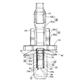
図1−図3に示すように、テザークリップ10は、ボデー取付部20と、ボデー取付部20部位に形成された係止爪30と、を備えている。テザークリップ10は、さらに、座部50と、テザー部52と、アンカー部54と、テザー部52の両側に設けられた係合保持部56と、を備えていてもよい。ボデー取付部20は座部50と直交するかまたはほぼ直交する方向に座部50から一側に延び、テザー部52とアンカー部54と係合保持部56は座部50からボデー取付部20と反対側に延びる。ボデー取付部20は、係止爪30
と座部50との間の部位に、ボデー取付部20から半径方向外方に延びボデー取付部軸方向に可撓性をもつフランジ部42を有していてもよい。
As shown in FIGS. 1 to 3, the
A
ピラーガーニッシュ取付装置60のうち、テザークリップ10の説明において必要となる部分を、予め、概略説明する。詳細は後述のピラーガーニッシュ取付装置60にて説明する。
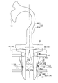
図11に示すように、テザークリップ10は、ボデー取付部20部位にて車両ボデーパネル80に取付けられる。テザークリップ10は、ボデー取付部20をボデーパネル80に設けられたクリップ取付孔82に挿通させ、フランジ部42と係止爪30とでクリップ取付孔82の縁部を挟むことにより、ボデーパネル80に取付けられる。また、テザークリップ10は、係合保持部56と座部50によりピラーガーニッシュ70のテザー収納部74の底壁部76に形成された長方形状の係止孔76aの縁部を挟むことによりピラーガーニッシュ70と係合される。カーテンエアバッグ90の展開時にカーテンエアバッグ90に押されてピラーガーニッシュ70がボデーパネル80から離れる方向に開く。ピラーガーニッシュ70が途中まで開いた時にアンカー部54がピラーガーニッシュ70の係止孔76aの縁部と係合し、それ以上にピラーガーニッシュ70が開くことが阻止され、ピラーガーニッシュ70の飛散が規制される。
Of the pillar
As shown in FIG. 11, the
図1−図6に示すように、テザークリップ10のうちボデー取付部20は、外面22を有する中空体からなる。ボデー取付部20は、ボデー取付部20の軸芯が延びる方向である軸方向を有する。
As shown in FIGS. 1 to 6, the
係止爪30は、ボデー取付部20に1つ以上設けられる。図示例では、係止爪30がボデー取付部20にボデー取付部20の軸芯を挟んで一対設けられた場合を示している。
係止爪30は、ボデー取付部22の軸方向と平行な長手方向を有する。係止爪30は、係止爪長手方向の一端でボデー取付部20に結合され、この長手方向一端を除きスリット24によりボデー取付部20から切り離されている。ボデー取付部20を上下方向に向け座部50をボデー取付部20の上側に配置した姿勢においては、スリット24は逆U字状になる。逆U字状に配置された場合のスリット24の2つの下端は、スリット24の端24aを構成する。
One or
The locking
係止爪30は、係止爪長手方向にスリットの端24aから座部50側に向かって、傾斜面34と、爪主部32と、延設面36と、係止解除操作部40と、を有し、内部に内面38を有する。以下に各部を詳細に説明する。
The locking
爪主部32は、係止爪30に一体に形成され係止爪長手方向途中部位でボデー取付部20の外面22よりもボデー取付部20の半径方向外方に突出している。爪主部32は、ボデー取付部22の軸方向に延びる外面32aと、外面32aに接続しボデー取付部22の軸方向と直交する方向に延びる平面32bと、平面32bに接続し平面32bと延設面36との間に傾斜して延びる連絡面32cを有する。外面32aは、クリップ取付孔82の内径よりも半径方向外方に位置し、ボデー取付部20の軸芯を中心に円弧をなして周方向に延びる。
The claw
傾斜面34は、係止爪30に一体に形成され、爪主部32より係止爪長手方向の一端側に位置する傾斜の起点34aと爪主部32との間にわって延び、ボデー取付部軸方向に対して傾斜されている。傾斜面34の傾斜の方向は、傾斜の起点34aから爪主部32に向かって、ボデー取付部20の半径方向にボデー取付部20の軸芯からの距離が大きくなる方向である。傾斜面34は、ボデー取付部20の軸芯を中心に円弧をなして周方向に延びる。
The
延設面36は、ボデー取付部22の軸方向に延び、ボデー取付部20の軸芯を中心に円弧をなして周方向に延びる。テザークリップ10をボデーパネル80に装着した時には、延設面36がクリップ取付孔82の縁部の内面に、ボデー取付部半径方向に対向する。
The extending
係止解除操作部40は、係止爪30に一体に設けられ、係止爪長手方向の他端(係止爪30のボデー取付部20への連結側の一端と反対側の端)からボデー取付部半径方向外方に延びる。係止解除操作部40は、爪主部32の外面32aよりもボデー取付部22の軸芯から離れた位置まで延びる。係止解除操作部40は、サービス時にテザークリップ10をボデーパネル80から取り外す時に操作される。係止解除操作部40をボデー取付部22の軸芯側に押すことにより爪主部32をボデー取付部22の軸芯側に変位させ、爪主部32の外面32aをクリップ取付孔82の半径より内径側に変位させて爪主部32がクリップ取付孔82を挿通可能にする。
The unlocking
傾斜面34の傾斜の起点34aの位置と、係止爪長手方向の一端側のスリット24の端24aの位置とは、ボデー取付部軸方向に互いにほぼ一致されている。
この場合、係止爪30の幅方向の端部で傾斜の起点34aとスリット24の端24aとがボデー取付部軸方向に互いにほぼ一致していればよい。傾斜面34の外面がボデー取付部20の軸芯を中心として周方向に延びる円弧面になっているため、傾斜の起点34aはボデー取付部軸方向に円弧を描くが、係止爪30の幅方向の端部で傾斜面34の傾斜の起点34aの位置がスリット24の端24aの位置とボデー取付部軸方向に互いにほぼ一致していればよい。
また、「ほぼ一致」は、スリット24の幅寸法程度の、ボデー取付部軸方向ずれは許容されるものとする。これは、テザークリップ10が型成形によって作製されるので、高精度の寸法を出すのが難しいためである。
The position of the
In this case, the
In addition, “substantially coincidence” is assumed to allow an axial displacement of the body attachment portion about the width dimension of the
スリット24のボデー取付部軸方向終端部は、図7に示すように、スリット24のボデー取付部軸方向に延びる2辺24b、24cの間にわたってスリットの正面視にて半円形状に延びる半円形部24dを有する。そして、スリット24の端24aは、この半円形部24dのボデー取付部軸方向端点である。なお、半円形部24dの「半円形」は「ほぼ半円形」、たとえば半長円形、楕円形を含む。
As shown in FIG. 7, the end portion in the axial direction of the body mounting portion of the
本発明のテザークリップ10では、前述の比較テザークリップ100に対して、つぎの構造をとる。ただし、比較テザークリップ100は、傾斜面134の傾斜の起点134aがスリットの端124aから爪主部132側に距離Bだけ隔たっておりスリットの端124aから傾斜面の傾斜の起点134aまで寸法Aの一定厚みを有する係止爪130を有し、スリット端124aが角124eを持つ以外は本発明のテザークリップ10と同一構造かまたはほぼ同一構造とされている。
The
本発明のテザークリップ10では、スリットの端24aのボデー取付部軸方向位置が比較テザークリップ100のスリットの端124aのボデー取付部軸方向位置と等しくされたままとされている。
この状態で、傾斜面34の傾斜の起点34aのボデー取付部軸方向位置が、比較テザークリップ100のスリットの端124aのボデー取付部軸方向位置にほぼ一致する位置にまでボデー取付部軸方向に移動されている。
In the
In this state, the body attachment portion axial position of the
本発明のテザークリップ10では、比較テザークリップ100の傾斜の起点134aをボデー取付部120の軸方向にスリットの端124aまで移すことにより、傾斜面34の傾斜の起点34aの位置と、係止爪長手方向の一端側のスリット24の端24aの位置とが、ボデー取付部軸方向に互いにほぼ一致されている。すなわち、スリットの端124aをボデー取付部120の軸方向に傾斜の起点134aまで移すのではない。
これにより、本発明のテザークリップ10の傾斜面34のボデー取付部軸方向長さが、比較テザークリップ100の傾斜面134のボデー取付部軸方向長さより長くなり、本発明のテザークリップ10の傾斜面34の傾斜が比較テザークリップ100の傾斜面134の傾斜に比べて緩くなる。
In the
Thereby, the body mounting portion axial length of the
また、本発明のテザークリップ10では、テザークリップ10の傾斜面34の傾斜の起点34aでの係止爪30の内面38の位置、テザークリップ10のスリットの端24aから距離Bだけ隔たった位置での係止爪30の内面38の位置、およびテザークリップ10の傾斜面34の傾斜の起点34aでの係止爪30の厚み寸法が、それぞれ、比較テザークリップ100のスリットの端位置124aでの係止爪130の内面124aの位置、比較テザークリップ100のスリットの端124aから距離Bだけ隔たった位置での係止爪130の内面138の位置、および比較テザークリップ100のスリットの端位置124aでの係止爪130の厚み寸法Aと等しくされたままとされている。
Further, in the
この状態で、本発明のテザークリップ10のスリットの端24aから距離Bだけ隔たった位置での係止爪30の厚み寸法Tが、比較テザークリップ100のスリットの端124aから距離Bだけ隔たった位置での係止爪130の厚み寸法Aより大きくされている。
In this state, the thickness dimension T of the locking
ついで、テザークリップ10のボデー取付部20および係止爪30以外の部分、すなわち、座部50、テザー部52、アンカー部54、テザー部52の両側に設けられた係合保持部56の構造を説明する。
Next, the parts of the
図1−図3に示すように、座部50は厚みをもつほぼ矩形状の平板からなる。
スリット24の逆U字状の上辺は、少なくとも一部が、座部50の下面に懸かっていてもよい。
テザー部52および係合保持部56は、座部50から、ボデー取付部20と反対側に延びる。
As shown in FIGS. 1-3, the
At least a part of the upper side of the inverted U shape of the
The
図1−図3、図11に示すように、テザー部52は、座部50から立ち上がり直線状に延びる直線状部52aと、直線状部52aの座部50と反対側の端部に接続し湾曲する湾曲部52bとを有する。ただし、直線状部52aを省略して湾曲部52bが座部50から直接立ち上がってもよい。直線状部52aと湾曲部52bの、テザー部52の長手方向と直交する方向に切断して見た断面は矩形状である。湾曲部52bの湾曲の方向は、図11ではピラーガーニッシュ70の長手方向と直交する方向に向けられているが、ピラーガーニッシュ70の長手方向に向けられてもよい。以下では、ピラーガーニッシュ70の長手方向と直交する方向に向けられた場合で説明する。
As shown in FIG. 1 to FIG. 3 and FIG. 11, the
図1−図3、図11に示すように、アンカー部54は、テザー部52の座部50と反対側の端部に接続している。アンカー部54は、テザー部52に接続する側の端部から反対側の端部に向かって徐々に拡大する銀杏の葉に似た形状を有する。アンカー部54は長方形状の断面を有する。アンカー部54の長方形状断面の長辺は、ピラーガーニッシュ70の長方形状の係止孔76aの長辺より短く短辺より長く、アンカー部54の断面の短辺は、ピラーガーニッシュ70の長方形状の係止孔76aの短辺より短い。
As shown in FIG. 1 to FIG. 3 and FIG. 11, the
アンカー部54は、その断面長手方向を係止孔76aの長辺が延びる方向に合わせて係止孔76aを挿通し、係止孔76aを挿通後90度回転されて、ピラーガーニッシュ70の収納部74内に収納される。カーテンエアバッグ90の展開時に、ピラーガーニッシュ70から抜去力F(図11)を受けるとテザー部52が直線状に近づくように延びてピラーガーニッシュ70が開いていく。ピラーガーニッシュ70が途中まで開くとアンカー部54が係止孔76aの縁部と係合し、ピラーガーニッシュ70のそれ以上の開きが阻止さ
れ、ピラーガーニッシュ70の飛散が防止される。
The
図1−図3に示すように、係合保持部56は、テザー部52の両側に1つづつ、一対設けられる。係合保持部56は、座部50からテザー部52と同じ側に立ち上がる立上り部56aと、立上り部56aに接続し立上り部56aの立上り方向と直交する方向に膨出する膨出部56bを有する。
As shown in FIGS. 1 to 3, a pair of
膨出部56bは立上り部56aの立上り方向と直交する方向に弾性変形可能である。膨出部56bをピラーガーニッシュ70の係止孔76aに挿通させて収納部74に収納する時には膨出部56bが係止孔76aの縁部から押されて後退し係止孔76aを挿通する。挿通後、膨出部56bが元の膨出位置に弾性復帰し、膨出部56bと座部50との間に係止孔76aの縁部を挟み、テザークリップ10がピラーガーニッシュ70を係合保持する。この状態で、カーテンエアバッグ90の展開時に、ピラーガーニッシュ70から抜去力F(図11)を受けると、係止孔76aの縁部が膨出部56bを弾性変形させて膨出部56b部位を通過し、アンカー部54が係止孔76aの縁部と係合するまでピラーガーニッシュ70が開く。この状態でピラーガーニッシュ70が半開きとなり、ピラーガーニッシュ70とボデーパネル80との隙間を通ってカーテンエアバッグ90が車室内に展開する。図11では、半開きのピラーガーニッシュ70と展開したカーテンエアバッグ90が2点鎖線で示してある。
The bulging
〔ピラーガーニッシュ取付装置〕
つぎに、ピラーガーニッシュ取付装置60の構造を説明する。
ピラーガーニッシュ取付装置60は、クリップ取付孔82を有するボデーパネル80と、カーテンエアバッグ90を収納したピラーガーニッシュ70と、ピラーガーニッシュ70をボデーパネル80のクリップ取付孔82部位にてボデーパネル80に取り付けるのに用いられる上記のテザークリップ10と、を有する。
[Pillar garnish mounting device]
Next, the structure of the pillar
The pillar
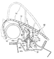
ボデーパネル80は、車両のフロントピラーパネルである。フロントピラーパネル80は、インナーパネル80a、リインホースメント80b、アウターパネル80cを有する。インナーパネル80aにはクリップ取付孔82が形成されている。ピラーガーニッシュ70は、クリップ取付孔82部位にて、テザークリップ10によりインナーパネル80aに取り付けられる。
The
カーテンエアバッグ90は、布製であり、折り畳まれた状態でピラーガーニッシュ70とボデーパネル80との間に配置される。カーテンエアバッグ90は、タブ部にて、テザークリップ10とは別部位に設けられた通常クリップによりボデーパネル80に取り付けられる。カーテンエアバッグ90の通常クリップによるボデーパネル80への取付けは、テザークリップ10によるピラーガーニッシュ70のボデーパネル80への取付け前に行われる。
The
ピラーガーニッシュ70は、ガーニッシュ本体72と、その背面側に、ピラーガーニッシュ長手方向の一部に少なくとも1つ形成されたテザー収納部74と、を有する。テザー収納部74は底壁部76を有し、底壁部76には長方形状の係止孔76aが形成されている。図11では、係止孔76aの長辺はピラーガーニッシュ長手方向に向けられている。係止孔76aの縁部がテザークリップ10の座部50と係合保持部56によって挟まれることにより、ピラーガーニッシュ70はテザークリップ10に保持される。
The
ピラーガーニッシュ70は、テザークリップ10がピラーガーニッシュ70に予め係合された状態で、テザークリップ10のボデー取付部20をボデーパネル80のクリップ取付孔82に挿入することにより、ボデーパネル80に取付けられる。挿入時に係止爪30
がクリップ取付孔82の縁部で押された時に、係止爪30はボデー取付部20の半径方向内方に撓みクリップ取付孔82部位を挿通できる。挿通後、係止爪30は元の位置に弾性により復帰する。取付け完了時には、クリップ取付孔82の縁部がフランジ部42と係止爪30とで挟まれる。フランジ部42がボデー取付部軸方向に可撓性を有するので、クリップ取付孔82の縁部と係止爪30との隙間(ガタ)は吸収される。
The
Is pushed at the edge of the
サービス時などにおいて、ピラーガーニッシュ70をボデーパネル80から外す必要が生じた時には、ピラーガーニッシュ70をボデーパネル80から離す方向に引っ張る。この時、底壁部76の係止孔76aが係合保持部56の膨出部56bを内方に弾性変位させて膨出部56bを通過し、アンカー部54が底壁部76の係止孔76aに係合して止まるまで、ピラーガーニッシュ70を移動させる。この状態では、ピラーガーニッシュ70とボデーパネル80との間に隙間ができるので、この隙間を通して手または治具を入れ、一対の係止解除操作部40を指または治具で挟んで係止解除操作部40を内方に弾性変位させる。一対の係止解除操作部40の内面同士が当接した時に、一対の係止爪30の爪主部32の外面32aの間隔がクリップ取付孔82の内径以下となるので、一対の係止爪30はクリップ取付孔82を挿通可能となる。この状態でボデー取付部20をクリップ取付孔82を通してボデーパネル80から引き抜き、テザークリップ10ごとピラーガーニッシュ70をボデーパネル80から取り外す。
When it becomes necessary to remove the
カーテンエアバッグ90は、車両側面衝突時およびロールオーバ時にインフレータから膨張用ガスが供給されて展開する。カーテンエアバッグ90の展開時にピラーガーニッシュ70はカーテンエアバッグ90の展開圧を受けてボデーパネル80から離れる方向に開く。図11に2点鎖線で示すように、ピラーガーニッシュ70が途中位置まで開くとアンカー部54が係止孔76aの縁部と係合してピラーガーニッシュ70のそれ以上の開きを阻止する。途中まで開いたピラーガーニッシュ70とボデーパネル80との間の隙間を通して、カーテンエアバッグ90はサイドウインドウガラスと乗員頭部との間に展開し、乗員頭部を拘束して保護する。
The
カーテンエアバッグ90の展開時にアンカー部54がピラーガーニッシュ70と係合した時には、カーテンエアバッグ90の展開荷重がピラーガーニッシュ70を介して、テザークリップ10に抜去荷重F(図11)としてかかる。そして、その反力として、ボデーパネル80のクリップ取付孔82の縁部からテザークリップ10の係止爪30に圧縮の剪断荷重がかかる。係止爪30が剪断破壊するピラーガーニッシュ70がテザークリップ10ごと飛散するので、テザークリップ10は、係止爪30が剪断荷重に耐えることができる以上の耐抜去力を持っていなければならない。
When the
<<作用、効果>>
〔テザークリップ〕
まず、テザークリップ10の作用、効果を説明する。
本発明のテザークリップ10では、傾斜面34の傾斜の起点34aの位置がスリットの端24aの位置にボデー取付部軸方向にほぼ一致されている。そのため、図5に示すように、スリットの端24aから距離Bだけ隔たった位置における係止爪30の厚さTが、比較テザークリップ100のスリットの端124aから距離Bだけ隔たった位置における係止爪130の厚さAに比べて厚くなる。その結果、係止爪30の根元部の曲げ剛性と耐座屈性が向上する。
<< Action and effect >>
[Tether clip]
First, the operation and effect of the
In the
図8は抜去荷重がかかった時のテザークリップ10の係止爪30の根元部の曲げと座屈の合成変形を示し、図9は抜去荷重がかかった時の比較テザークリップ100の係止爪130の根元部の曲げと座屈の合成変形を示す。
図8と図9との比較からわかるように、カーテンエアバッグ展開時にボデーパネル80の
クリップ取付孔82の縁部からテザークリップ10の係止爪30にボデー取付部軸方向に圧縮の剪断荷重がかかった時に、本発明では係止爪30の根元部での曲げ変形および座屈とそれらによる爪主部32の傾きが、比較テザークリップ100に比べて抑制される。爪主部32の傾きの抑制により、爪主部32における剪断面長さSpが比較テザークリップの剪断面長さScよりも大きくなる。その結果、テザークリップ10の耐抜去力が増大される。
抜去荷重試験を行ったところ、比較テザークリップ100の抜去荷重を100%とした場合に、本発明のテザークリップ10の抜去荷重は122%となり、耐抜力荷重が22%増大することが確認された。
FIG. 8 shows the combined deformation of the bending and buckling of the base portion of the locking
As can be seen from the comparison between FIG. 8 and FIG. 9, when the curtain airbag is deployed, a compressive shear load is applied in the axial direction of the body attachment portion from the edge of the
When the extraction load test was performed, it was confirmed that when the extraction load of the
また、図5に示すように、傾斜面34の傾斜の起点34aの位置がスリットの端24aの位置に移されている。そのため、比較テザークリップ100に比べて、係止爪30の曲げ点が係止解除操作部40の内面から遠くなる。その結果、係止爪30の爪主部32の外面間の寸法がクリップ取付孔82の直径と同一になる時の、一対の係止解除操作部40の内面同士の干渉量が減少する。また、係止解除操作部40の内面と係止爪32の曲げ点とのスパンが大きくなる。さらに、係止爪30の傾斜面34の角度が緩やかになる。これらの結果、図10に示すように、本発明のテザークリップ10の、クリップ取付孔82への挿入荷重が、比較テザークリップ100に比べて下がる。テザークリップ10の取外し荷重もテザークリップ10の挿入荷重に準じる。
Further, as shown in FIG. 5, the position of the
また、スリット24の端部形状がスリット正面視でほぼ半円形であるため、テザークリップ10に抜去荷重がかかった時に、スリットの端24aにノッチ効果が生じにくい。比較テザークリップ100のようにスリット端形状が角124eをもつ形状の場合、角124eから亀裂が発生するおそれがあるが、本発明のテザークリップ10ではスリット24の端部形状ほぼ半円形のため、亀裂発生が抑制される。また、係止爪30のスリット端24aでの幅がほぼ半円形の直径だけ増大されるので、係止爪30の根元の強度が向上し、これによっても係止爪30の根元での破断が抑制される。
In addition, since the end shape of the
また、爪主部32がボデー取付部軸方向に延びる外面32aを有するので、傾斜面34が爪主部外面32aを介することなく直接爪主部上面32bまたは32cに接続する場合に比べて、爪主部32の厚さが厚くなる。これによって、爪主部32の剪断面長さSpが比較テザークリップ100の剪断面長さScより長くなり、比較テザークリップ100に比べ本発明のテザークリップ10の耐抜去力が増大される。ここで、「爪主部の剪断面長さ」とは、クリップ取付孔82の内面を通るボデー取付部軸方向に延びる面での、爪主部32の平面32bと傾斜面134との間のボデー取付部軸方向長さと定義する。連絡面32cとしないで平面32bとするのは、クリップ取付孔82の縁部からの荷重を平面32bで受けた時に、荷重のかかり位置が安定するからである。
Further, since the claw
爪主部32がボデー取付部軸方向と直交する平面32bを有するので、軸直交面32bで抜去荷重を受けた時点以後には、耐抜去力が安定する。もしも軸直交平面32bが斜面32cで構成された場合は、軸方向抜去荷重がかかった時に、斜面32cにボデー取付部半径方向内方に向かう分力が生じて爪主部32をボデー取付部半径方向内方に撓ませるので、剪断面が爪主部32の外側端に近づき、爪主部32の剪断面長さSpが小さくなってテザークリップ10の耐抜去力が低下するおそれがある。しかし、軸直交面32bを持つ爪主部32では、耐抜去力の低下が抑制される。
Since the claw
なお、傾斜面34の傾斜の起点34aの位置とスリットの端24aの位置とをボデー取付部軸方向にほぼ一致させる場合、傾斜面34の傾斜の起点34aのボデー取付部軸方向位置を比較テザークリップ100のスリットの端124aのボデー取付部軸方向位置にほぼ一致する位置にまでボデー取付部軸方向に移動されたので、本発明のテザークリップ1
0における係止爪30の根元部の曲げ剛性と耐座屈性の向上、およびそれによるテザークリップ10の耐抜去力の増大、並びに挿入、取外し荷重の減少が得られる。
これに対して、スリットの端24aのボデー取付部軸方向位置が比較テザークリップ100の傾斜面134の傾斜の起点134aのボデー取付部軸方向位置にまでボデー取付部軸方向に移動されると、上記効果は得られない。
When the position of the
Thus, the bending rigidity and buckling resistance of the base portion of the locking
On the other hand, when the body attachment portion axial position of the
傾斜の起点34aの位置をスリットの端124aに近づくように移動させた場合、(爪主部32の平面32bからスリット端24aまでの係止爪30のボデー取付部軸方向長さ)/(係止爪30の幅)の比Rが約1.9以上となる。
一方、スリットの端124aを傾斜の起点34aの位置に近づくように移動させた場合、(爪主部32の平面32bからスリット端24aまでの係止爪30のボデー取付部軸方向長さ)/(係止爪30の幅)の比Rが約1.0〜1.85となる。
傾斜の起点34aの位置とスリットの端124aの位置をほぼ一致させる場合、傾斜の起点34aの位置とスリットの端124aの位置のどちらを移動させたかの判別は、上記の比Rが約1.9以上かそれ未満かを1つの目安とすることができる。
なお、係止爪30の幅寸法は、スリット端以外での幅寸法である。
When the position of the
On the other hand, when the
When the position of the
In addition, the width dimension of the latching
また、係止爪30の根元部の厚みと剛性を増大するのに係止爪30の内面位置を内方にずらしていない。その結果、一対の係止解除操作部40の内面同士の干渉量は増大せず、テザークリップ10の、ボデー80のクリップ取付孔82への挿入荷重は、比較テザークリップ100に比べて増大しない。傾斜面34が長くなることにより、図10に示すように、テザークリップ10の挿入荷重の最大値は、比較テザークリップ100に比べてむしろ低下している。
Further, in order to increase the thickness and rigidity of the base portion of the locking
〔ピラーガーニッシュ取付装置〕
ピラーガーニッシュ取付装置60では、上記のテザークリップ10を用いたので、比較テザークリップ100を用いたピラーガーニッシュ取付装置よりも、テザークリップ10の耐抜去力を上げることができ、カーテンエアバッグ90の展開時におけるピラーガーニッシュ70の飛散を抑制することができる。また、テザークリップ10の耐抜去力の向上により、カーテンエアバッグ90の展開圧を上げることができ、それによってカーテンエアバッグ90の展開時間を短縮することも可能となる。
また、ボデーパネル80、クリップ取付孔82、およびカーテンエアバッグ90を収納したピラーガーニッシュ70の構造を従来から変更する必要がなく、周辺構造の設計変更を伴わない。
[Pillar garnish mounting device]
Since the pillar
Moreover, it is not necessary to change the structure of the
以上はクリップ10としてテザークリップ10を、取付装置60としてピラーガーニッシュ取付装置60を例にとって説明したが、本発明はこれらに限るものではなく、クリップ10はカーテンエアバッグ取付クリップであってもよいし、取付装置60がカーテンエアバッグ取付装置60であってもよい。
カーテンエアバッグ取付クリップの場合、カーテンエアバッグ取付クリップ10のボデー取付部20の構造は、ボデー取付部20の外面形状がほぼ長方形であること以外は、テザークリップ10のボデー取付部20の構造を準用できる。
カーテンエアバッグ取付装置の場合、クリップ10がボデーパネル80に取り付けるのはカーテンエアバッグ90であるが、テザークリップ取付装置の場合の場合、クリップ10がボデーパネル80に取り付けるのはピラーガーニッシュ70である。
In the above description, the
In the case of the curtain airbag mounting clip, the structure of the
In the case of the curtain airbag attachment device, the
10 テザークリップ
20 ボデー取付部
22 外面
24 スリット
24a スリットの端
30 係止爪
32 爪主部
32a 外面
32b ボデー取付部軸方向と直交する平面
34 傾斜面
34a 傾斜の起点
36 係止爪の延設面
38 係止爪の内面
40 係止解除操作部
60 ピラーガーニッシュ取付装置
70 ピラーガーニッシュ
80 ボデーパネル
82 クリップ取付孔
90 カーテンエアバッグ
100 比較テザークリップ
DESCRIPTION OF
Claims (5)
ボデー取付部はボデー取付部の軸方向に延びており、
係止爪は、ボデー取付部の軸方向と平行な長手方向を有し該長手方向の一端にボデー取付部との結合部を有し該結合部を除きスリットによりボデー取付部から切り離されており、
前記係止爪は、係止爪に一体に形成され係止爪長手方向途中部位でボデー取付部の外面よりボデー取付部の半径方向外方に突出する爪主部と、係止爪に一体に設けられ係止爪の長手方向の結合部と反対側の端部からボデー取付部の半径方向外方に延びる係止解除操作部と、を有しており、
爪主部は、ボデー取付部の軸方向と平行に延びる外面と、該外面の結合部と反対側の端部に接続しボデー取付部軸方向と直交する方向に延びる平面と、ボデー取付部の軸方向に対して傾斜され前記外面よりも結合部側にある傾斜の起点と前記外面の結合部側の端部との間にわたって直線状に延びる傾斜面と、有している、
クリップであって、
前記傾斜面の傾斜の起点のボデー取付部軸方向位置と前記スリットの結合部側端のボデー取付部軸方向位置とがボデー取付部軸方向に互いにほぼ一致されており、
前記傾斜面が前記外面の結合部側の端部と前記スリットの結合部側端と同じボデー取付部軸方向位置にある結合部外表面とを結んでいる、クリップ。 A body mounting portion and a locking claw;
The body mounting part extends in the axial direction of the body mounting part ,
The locking claw is detached from the body mounting portion by a slit except the coupling portion has a coupling portion between the body mounting portion in the longitudinal direction of the end having parallel longitudinal and axial direction of the body attachment part ,
The locking claw has a claw main portion projecting radially outward of the body mounting portion than the outer surface of the body mounting portion is formed latching claws longitudinally middle portion integrally claw, integrally with the engaging claw and unlocking operating portion extending from the longitudinal direction of the coupling portion of the provided locking claws opposite end radially outwardly of the body attachment part, has a,
The claw main portion includes an outer surface extending in parallel with the axial direction of the body mounting portion, a flat surface connected to an end opposite to the coupling portion of the outer surface and extending in a direction perpendicular to the axial direction of the body mounting portion, An inclined surface that is inclined with respect to the axial direction and extends linearly between a starting point of an inclination on the coupling portion side of the outer surface and an end portion on the coupling portion side of the outer surface ,
A clip,
The body mounting portion axial position of the origin of the inclination of the inclined surface and the body attachment part axial position of the coupling portion side end of the slit are substantially coincident with each other in the body mounting portion axial direction,
The clip in which the inclined surface connects the end portion on the coupling portion side of the outer surface and the coupling portion outer surface at the same body attachment portion axial position as the coupling portion side end of the slit .
前記クリップの前記傾斜面の傾斜の起点での前記係止爪の内面位置、前記クリップの前記スリットの端から距離Bだけ隔たった位置での前記係止爪の内面位置、および前記クリップの前記傾斜面の傾斜の起点での前記係止爪の厚み寸法が、それぞれ、比較クリップのスリットの端位置での係止爪の内面位置、比較クリップのスリットの端から距離Bだけ隔たった位置での係止爪の内面位置、および比較クリップのスリットの端位置での係止爪の厚
み寸法Aと等しくされたまま、
前記クリップの前記スリットの端から距離Bだけ隔たった位置での前記係止爪の厚み寸法Tが、比較クリップのスリットの端から距離Bだけ隔たった位置での係止爪の厚み寸法Aより大きくされている、請求項1または請求項2記載のクリップ。 The starting point of the inclined surface of the inclined surface is separated from the end of the slit by the distance B from the end of the slit, and has a locking claw having a constant thickness A from the end of the slit to the starting point of the inclined surface of the inclined surface. Compared to the comparison clip that has the same structure as the clip except for having a corner,
The position of the inner surface of the locking claw at the starting point of the inclination of the inclined surface of the clip, the position of the inner surface of the locking claw at a position separated from the end of the slit of the clip by a distance B, and the inclination of the clip The thickness dimension of the engaging claw at the starting point of the surface inclination is the position of the inner surface of the engaging claw at the end position of the slit of the comparison clip and the position separated from the end of the slit of the comparison clip by the distance B, respectively. While keeping the inner surface position of the pawl and the thickness dimension A of the pawl at the end position of the slit of the comparison clip,
A thickness dimension T of the locking claw at a position spaced from the end of the slit of the clip by a distance B is larger than a thickness dimension A of the locking claw at a position spaced by a distance B from the end of the slit of the comparison clip. The clip according to claim 1 or 2 , wherein the clip is provided.
Priority Applications (1)
| Application Number | Priority Date | Filing Date | Title |
|---|---|---|---|
| JP2012047766A JP5776592B2 (en) | 2012-03-05 | 2012-03-05 | Clip and pillar garnish or curtain airbag mounting device using the clip |
Applications Claiming Priority (1)
| Application Number | Priority Date | Filing Date | Title |
|---|---|---|---|
| JP2012047766A JP5776592B2 (en) | 2012-03-05 | 2012-03-05 | Clip and pillar garnish or curtain airbag mounting device using the clip |
Publications (2)
| Publication Number | Publication Date |
|---|---|
| JP2013180725A JP2013180725A (en) | 2013-09-12 |
| JP5776592B2 true JP5776592B2 (en) | 2015-09-09 |
Family
ID=49271691
Family Applications (1)
| Application Number | Title | Priority Date | Filing Date |
|---|---|---|---|
| JP2012047766A Expired - Fee Related JP5776592B2 (en) | 2012-03-05 | 2012-03-05 | Clip and pillar garnish or curtain airbag mounting device using the clip |
Country Status (1)
| Country | Link |
|---|---|
| JP (1) | JP5776592B2 (en) |
Families Citing this family (11)
| Publication number | Priority date | Publication date | Assignee | Title |
|---|---|---|---|---|
| US9592786B2 (en) | 2013-06-06 | 2017-03-14 | Toyota Jidosha Kabushiki Kaisha | Clip, curtain airbag mounting structure and pillar garnish mounting structure |
| JP5895923B2 (en) * | 2013-11-25 | 2016-03-30 | トヨタ自動車株式会社 | Clip and pillar garnish mounting structure |
| JP6128233B2 (en) * | 2013-11-29 | 2017-05-24 | トヨタ自動車株式会社 | Clip and pillar garnish mounting structure |
| JP6107629B2 (en) * | 2013-12-06 | 2017-04-05 | 豊田合成株式会社 | Head protection airbag device |
| JP5888346B2 (en) | 2014-01-20 | 2016-03-22 | トヨタ自動車株式会社 | Clip and pillar garnish mounting structure |
| JP5907190B2 (en) | 2014-01-29 | 2016-04-26 | トヨタ自動車株式会社 | Pillar garnish mounting structure and tether clip |
| JP6217500B2 (en) * | 2014-04-14 | 2017-10-25 | トヨタ自動車株式会社 | Pillar garnish mounting structure |
| JP6314698B2 (en) * | 2014-06-30 | 2018-04-25 | トヨタ自動車株式会社 | Clip and pillar garnish mounting structure |
| JP6715037B2 (en) * | 2016-03-04 | 2020-07-01 | 株式会社 Mtg | Beauty device |
| KR101856526B1 (en) * | 2016-10-12 | 2018-05-11 | 주식회사 서연이화 | Tether clip for vehicle |
| KR102709305B1 (en) * | 2022-02-11 | 2024-09-25 | 주식회사 프로스코 | Clip structure |
Family Cites Families (5)
| Publication number | Priority date | Publication date | Assignee | Title |
|---|---|---|---|---|
| JP3633537B2 (en) * | 2001-09-27 | 2005-03-30 | トヨタ自動車株式会社 | Mounting structure for interior parts for vehicles |
| JP4928235B2 (en) * | 2006-11-22 | 2012-05-09 | 大和化成工業株式会社 | Attachment structure for vehicle curtain airbag clip and pillar garnish, and curtain airbag clip |
| JP5377954B2 (en) * | 2008-12-24 | 2013-12-25 | 大和化成工業株式会社 | Cushion clip for vehicle |
| JP5227200B2 (en) * | 2009-01-09 | 2013-07-03 | 株式会社パイオラックス | Airbag clip mounting structure |
| JP5451366B2 (en) * | 2009-12-24 | 2014-03-26 | 株式会社ニフコ | clip |
-
2012
- 2012-03-05 JP JP2012047766A patent/JP5776592B2/en not_active Expired - Fee Related
Also Published As
| Publication number | Publication date |
|---|---|
| JP2013180725A (en) | 2013-09-12 |
Similar Documents
| Publication | Publication Date | Title |
|---|---|---|
| JP5776592B2 (en) | Clip and pillar garnish or curtain airbag mounting device using the clip | |
| JP4870488B2 (en) | High fixing strength fixture | |
| JP4535892B2 (en) | clip | |
| JP5742691B2 (en) | Tether clip and garnish attachment device having the same | |
| JP5888346B2 (en) | Clip and pillar garnish mounting structure | |
| CN105308333B (en) | Clip, curtain air bag mounting structure and post luster mounting mechanism | |
| JP5668716B2 (en) | Mounting clip and curtain airbag mounting device | |
| JP2013113419A5 (en) | ||
| JP5967114B2 (en) | Tether clip and pillar garnish mounting structure | |
| WO2014020655A1 (en) | Securing means, securing means extraction structure and curtain airbag-securing device | |
| JP5783033B2 (en) | Garnish mounting device and tether clip | |
| US9464647B2 (en) | Pillar garnish mounting structure and tether clip | |
| JP5776644B2 (en) | Fixing device and curtain airbag fixing device | |
| JP6623742B2 (en) | Clip and pillar garnish mounting structure | |
| JP2011196397A (en) | Fixing structure by clip of installation part to panel | |
| JP4244132B2 (en) | clip | |
| JP6766623B2 (en) | Pillar garnish mounting structure and tether clip | |
| JP6464998B2 (en) | Pillar garnish mounting structure using tether clips and tether clips | |
| JP2015102152A (en) | Clip and pillar garnish mounting structure | |
| JP5895923B2 (en) | Clip and pillar garnish mounting structure | |
| JP2011218877A (en) | Curtain airbag mounting apparatus | |
| JP6648519B2 (en) | Mounting clip and mounting structure for mounting object using it | |
| JP2018095008A (en) | Pillar garnish mounting structure and tether clip | |
| JP6635009B2 (en) | Pillar garnish mounting structure and tether clip | |
| JP2023006581A (en) | Mounting clip and curtain air bag device for vehicle |
Legal Events
| Date | Code | Title | Description |
|---|---|---|---|
| A621 | Written request for application examination |
Free format text: JAPANESE INTERMEDIATE CODE: A621 Effective date: 20140421 |
|
| A131 | Notification of reasons for refusal |
Free format text: JAPANESE INTERMEDIATE CODE: A131 Effective date: 20150127 |
|
| A977 | Report on retrieval |
Free format text: JAPANESE INTERMEDIATE CODE: A971007 Effective date: 20150129 |
|
| A521 | Request for written amendment filed |
Free format text: JAPANESE INTERMEDIATE CODE: A523 Effective date: 20150326 |
|
| TRDD | Decision of grant or rejection written | ||
| A01 | Written decision to grant a patent or to grant a registration (utility model) |
Free format text: JAPANESE INTERMEDIATE CODE: A01 Effective date: 20150609 |
|
| A61 | First payment of annual fees (during grant procedure) |
Free format text: JAPANESE INTERMEDIATE CODE: A61 Effective date: 20150622 |
|
| R151 | Written notification of patent or utility model registration |
Ref document number: 5776592 Country of ref document: JP Free format text: JAPANESE INTERMEDIATE CODE: R151 |
|
| LAPS | Cancellation because of no payment of annual fees |