JP5777854B2 - 液体噴出器 - Google Patents
液体噴出器 Download PDFInfo
- Publication number
- JP5777854B2 JP5777854B2 JP2010043108A JP2010043108A JP5777854B2 JP 5777854 B2 JP5777854 B2 JP 5777854B2 JP 2010043108 A JP2010043108 A JP 2010043108A JP 2010043108 A JP2010043108 A JP 2010043108A JP 5777854 B2 JP5777854 B2 JP 5777854B2
- Authority
- JP
- Japan
- Prior art keywords
- stem
- head
- cylinder
- opening
- discharge port
- Prior art date
- Legal status (The legal status is an assumption and is not a legal conclusion. Google has not performed a legal analysis and makes no representation as to the accuracy of the status listed.)
- Active
Links
Images

Classifications
-
- B—PERFORMING OPERATIONS; TRANSPORTING
- B05—SPRAYING OR ATOMISING IN GENERAL; APPLYING FLUENT MATERIALS TO SURFACES, IN GENERAL
- B05B—SPRAYING APPARATUS; ATOMISING APPARATUS; NOZZLES
- B05B1/00—Nozzles, spray heads or other outlets, with or without auxiliary devices such as valves, heating means
- B05B1/34—Nozzles, spray heads or other outlets, with or without auxiliary devices such as valves, heating means designed to influence the nature of flow of the liquid or other fluent material, e.g. to produce swirl
- B05B1/3405—Nozzles, spray heads or other outlets, with or without auxiliary devices such as valves, heating means designed to influence the nature of flow of the liquid or other fluent material, e.g. to produce swirl to produce swirl
- B05B1/341—Nozzles, spray heads or other outlets, with or without auxiliary devices such as valves, heating means designed to influence the nature of flow of the liquid or other fluent material, e.g. to produce swirl to produce swirl before discharging the liquid or other fluent material, e.g. in a swirl chamber upstream the spray outlet
- B05B1/3421—Nozzles, spray heads or other outlets, with or without auxiliary devices such as valves, heating means designed to influence the nature of flow of the liquid or other fluent material, e.g. to produce swirl to produce swirl before discharging the liquid or other fluent material, e.g. in a swirl chamber upstream the spray outlet with channels emerging substantially tangentially in the swirl chamber
- B05B1/3431—Nozzles, spray heads or other outlets, with or without auxiliary devices such as valves, heating means designed to influence the nature of flow of the liquid or other fluent material, e.g. to produce swirl to produce swirl before discharging the liquid or other fluent material, e.g. in a swirl chamber upstream the spray outlet with channels emerging substantially tangentially in the swirl chamber the channels being formed at the interface of cooperating elements, e.g. by means of grooves
- B05B1/3436—Nozzles, spray heads or other outlets, with or without auxiliary devices such as valves, heating means designed to influence the nature of flow of the liquid or other fluent material, e.g. to produce swirl to produce swirl before discharging the liquid or other fluent material, e.g. in a swirl chamber upstream the spray outlet with channels emerging substantially tangentially in the swirl chamber the channels being formed at the interface of cooperating elements, e.g. by means of grooves the interface being a plane perpendicular to the outlet axis
-
- B—PERFORMING OPERATIONS; TRANSPORTING
- B05—SPRAYING OR ATOMISING IN GENERAL; APPLYING FLUENT MATERIALS TO SURFACES, IN GENERAL
- B05B—SPRAYING APPARATUS; ATOMISING APPARATUS; NOZZLES
- B05B11/00—Single-unit hand-held apparatus in which flow of contents is produced by the muscular force of the operator at the moment of use
- B05B11/01—Single-unit hand-held apparatus in which flow of contents is produced by the muscular force of the operator at the moment of use characterised by the means producing the flow
- B05B11/10—Pump arrangements for transferring the contents from the container to a pump chamber by a sucking effect and forcing the contents out through the dispensing nozzle
- B05B11/1042—Components or details
- B05B11/1043—Sealing or attachment arrangements between pump and container
- B05B11/1046—Sealing or attachment arrangements between pump and container the pump chamber being arranged substantially coaxially to the neck of the container
- B05B11/1047—Sealing or attachment arrangements between pump and container the pump chamber being arranged substantially coaxially to the neck of the container the pump being preassembled as an independent unit before being mounted on the container
Landscapes
- Containers And Packaging Bodies Having A Special Means To Remove Contents (AREA)
Description
ピストン39と吸入弁40との間に設けた逆止弁43によって、容器20を起立させた状態は勿論、容器20を倒立させた状態でも内容物を噴霧させることができるようにしたものがある(例えば、特許文献1参照)。
当該排出口を、ステムの上端に形成し、当該排出口を形作る上端を、排出弁の先端が着座する弁座として構成し、
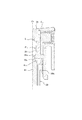
前記ヘッドの側面に形成された環状の凹溝に、このヘッドを通して圧送された内容物を外界に噴出させる開孔を有し当該ヘッドとの間に流路を形成するノズルチップを設け、
前記環状の凹溝によって該環状の凹溝の内側に前記ヘッドと一体に形成された円柱部の端面に、前記ノズルチップの開孔に通じる複数の流路を形成する複数の端面側凹溝を形成し、
前記ヘッドの前記円柱部の側面に、前記空間に開口して前記複数の端面側凹溝のそれぞれに通じる複数の流路を形成する複数の側面側凹溝を設け、
前記空間の一部として、前記ヘッドの側面とステムの外周面との間に、ステムの上端から前記環状の凹溝の下端を超える位置まで上下に延びると共に前記円柱部とステムとの間の全面に亘って形成された隙間を設け、当該隙間を通じて内容物を圧送させることを特徴とするものである。
2 フランジ
3 装着部材
4 肩部
5 補助シリンダ
6 ステム
7 摺動部
8 ヘッド
9 ピストン
10 吸入弁
11 排出弁
11a 先端
11b 上端
12 ノズルチップ
12a 開孔
12b 隔壁
12c 周壁
12g1 凹溝
12g2 凹溝
12a1 大径部
12a2 小径部
13 スペーサ
13a フィン
13b ピン
Claims (3)
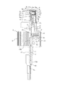
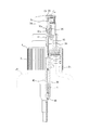
- 容器口部の内側を通って垂下するシリンダと、このシリンダを固定し当該シリンダの補助シリンダが起立する装着部材と、この装着部材の補助シリンダの内側を摺動するステムと、このステムを嵌合する凹部を有し当該ステムとの間に形成した空間を通して内容物が圧送されるヘッドと、このヘッドの押し下げ及び復帰によりシリンダ及びステムの内側を摺動して内容物を吸引、加圧及び圧送するピストンと、このピストンの摺動に応動してシリンダの吸入口を開閉する吸入弁と、ピストンの摺動に応動してステムの排出口を開閉してヘッドに内容物を圧送する排出弁とを備え、
当該排出口を、ステムの上端に形成し、当該排出口を形作る上端を、排出弁の先端が着座する弁座として構成し、
前記ヘッドの側面に形成された環状の凹溝に、このヘッドを通して圧送された内容物を外界に噴出させる開孔を有し当該ヘッドとの間に流路を形成するノズルチップを設け、
前記環状の凹溝によって該環状の凹溝の内側に前記ヘッドと一体に形成された円柱部の端面に、前記ノズルチップの開孔に通じる複数の流路を形成する複数の端面側凹溝を形成し、
前記ヘッドの前記円柱部の側面に、前記空間に開口して前記複数の端面側凹溝のそれぞれに通じる複数の流路を形成する複数の側面側凹溝を設け、
前記空間の一部として、前記ヘッドの側面とステムの外周面との間に、ステムの上端から前記環状の凹溝の下端を超える位置まで上下に延びると共に前記円柱部とステムとの間の全面に亘って形成された隙間を設け、当該隙間を通じて内容物を圧送させることを特徴とする液体噴出器。 - 請求項1において、前記ノズルチップの開孔が位置する部分に、当該開孔に向かって突出する凸部を設けたことを特徴とする液体噴出器。
- 請求項1又は2において、前記排出口を、ステムの先端を内側に向かって環状に折り曲げることで当該ステムの上端に形成し、当該排出口を形作る上端を、排出弁の先端が着座する弁座として構成したことを特徴とする液体噴出器。
Priority Applications (1)
| Application Number | Priority Date | Filing Date | Title |
|---|---|---|---|
| JP2010043108A JP5777854B2 (ja) | 2010-02-26 | 2010-02-26 | 液体噴出器 |
Applications Claiming Priority (1)
| Application Number | Priority Date | Filing Date | Title |
|---|---|---|---|
| JP2010043108A JP5777854B2 (ja) | 2010-02-26 | 2010-02-26 | 液体噴出器 |
Publications (2)
| Publication Number | Publication Date |
|---|---|
| JP2011177628A JP2011177628A (ja) | 2011-09-15 |
| JP5777854B2 true JP5777854B2 (ja) | 2015-09-09 |
Family
ID=44689769
Family Applications (1)
| Application Number | Title | Priority Date | Filing Date |
|---|---|---|---|
| JP2010043108A Active JP5777854B2 (ja) | 2010-02-26 | 2010-02-26 | 液体噴出器 |
Country Status (1)
| Country | Link |
|---|---|
| JP (1) | JP5777854B2 (ja) |
Families Citing this family (1)
| Publication number | Priority date | Publication date | Assignee | Title |
|---|---|---|---|---|
| JP6652380B2 (ja) * | 2015-12-25 | 2020-02-19 | 株式会社吉野工業所 | ノズルヘッド機構 |
Family Cites Families (5)
| Publication number | Priority date | Publication date | Assignee | Title |
|---|---|---|---|---|
| JPS5093305U (ja) * | 1973-12-26 | 1975-08-06 | ||
| JPS5620048Y2 (ja) * | 1975-06-24 | 1981-05-13 | ||
| JP2544718Y2 (ja) * | 1990-08-31 | 1997-08-20 | ぺんてる株式会社 | 液体噴出具の噴出部 |
| JP3957960B2 (ja) * | 2000-08-31 | 2007-08-15 | 株式会社吉野工業所 | 縦形液体噴出ポンプ |
| JP3836312B2 (ja) * | 2000-09-29 | 2006-10-25 | 株式会社吉野工業所 | 液体噴出ポンプ |
-
2010
- 2010-02-26 JP JP2010043108A patent/JP5777854B2/ja active Active
Also Published As
| Publication number | Publication date |
|---|---|
| JP2011177628A (ja) | 2011-09-15 |
Similar Documents
| Publication | Publication Date | Title |
|---|---|---|
| JP5936991B2 (ja) | 噴出ヘッド及び、それを備える容器 | |
| KR100692457B1 (ko) | 축압식 액체 분출기 | |
| JP5483414B2 (ja) | 押下ヘッド付き吐出器 | |
| JP5777854B2 (ja) | 液体噴出器 | |
| JP2011177630A (ja) | 液体噴出器 | |
| JP6602185B2 (ja) | 吐出ポンプ | |
| JP5128253B2 (ja) | 噴出ヘッド | |
| JP5483344B2 (ja) | 噴霧器 | |
| JP5567450B2 (ja) | トリガー式液体噴出器 | |
| JP2009173319A (ja) | ピストンおよびそのピストンを使用した流動体容器 | |
| JP5545763B2 (ja) | トリガー式液体噴出容器 | |
| KR20130089227A (ko) | 펌프디스펜서의 푸시헤드유닛 | |
| JP2007105365A (ja) | 鼻腔用噴射器 | |
| JP6158045B2 (ja) | トリガー式液体噴出器 | |
| CN212530684U (zh) | 一种香水卡口喷雾泵 | |
| JP5419753B2 (ja) | 噴出ヘッド | |
| JP3173465U (ja) | 直立および倒立状態でも使用可能な噴出器装置 | |
| JP5829009B2 (ja) | 噴霧ノズル | |
| JP3827408B2 (ja) | 噴出器 | |
| JP2012179519A (ja) | トリガー式液体噴出器 | |
| JP6612181B2 (ja) | トリガー式噴出器 | |
| JP4277990B2 (ja) | 液体噴出器 | |
| JP7851518B2 (ja) | 噴射口部材 | |
| KR102573275B1 (ko) | 액체 분사를 위한 용기 | |
| JP7694943B2 (ja) | 噴出ポンプ、および、噴出容器 |
Legal Events
| Date | Code | Title | Description |
|---|---|---|---|
| A621 | Written request for application examination |
Free format text: JAPANESE INTERMEDIATE CODE: A621 Effective date: 20120830 |
|
| A977 | Report on retrieval |
Free format text: JAPANESE INTERMEDIATE CODE: A971007 Effective date: 20131113 |
|
| A131 | Notification of reasons for refusal |
Free format text: JAPANESE INTERMEDIATE CODE: A131 Effective date: 20131119 |
|
| A521 | Request for written amendment filed |
Free format text: JAPANESE INTERMEDIATE CODE: A523 Effective date: 20140117 |
|
| A131 | Notification of reasons for refusal |
Free format text: JAPANESE INTERMEDIATE CODE: A131 Effective date: 20140218 |
|
| A521 | Request for written amendment filed |
Free format text: JAPANESE INTERMEDIATE CODE: A523 Effective date: 20140418 |
|
| A02 | Decision of refusal |
Free format text: JAPANESE INTERMEDIATE CODE: A02 Effective date: 20140715 |
|
| A521 | Request for written amendment filed |
Free format text: JAPANESE INTERMEDIATE CODE: A523 Effective date: 20141014 |
|
| A911 | Transfer to examiner for re-examination before appeal (zenchi) |
Free format text: JAPANESE INTERMEDIATE CODE: A911 Effective date: 20141021 |
|
| A912 | Re-examination (zenchi) completed and case transferred to appeal board |
Free format text: JAPANESE INTERMEDIATE CODE: A912 Effective date: 20141114 |
|
| A61 | First payment of annual fees (during grant procedure) |
Free format text: JAPANESE INTERMEDIATE CODE: A61 Effective date: 20150708 |
|
| R150 | Certificate of patent or registration of utility model |
Ref document number: 5777854 Country of ref document: JP Free format text: JAPANESE INTERMEDIATE CODE: R150 |