JP5793473B2 - Heater for bonding apparatus and cooling method thereof - Google Patents
Heater for bonding apparatus and cooling method thereof Download PDFInfo
- Publication number
- JP5793473B2 JP5793473B2 JP2012161304A JP2012161304A JP5793473B2 JP 5793473 B2 JP5793473 B2 JP 5793473B2 JP 2012161304 A JP2012161304 A JP 2012161304A JP 2012161304 A JP2012161304 A JP 2012161304A JP 5793473 B2 JP5793473 B2 JP 5793473B2
- Authority
- JP
- Japan
- Prior art keywords
- capillary
- insulating material
- heat insulating
- slits
- cooling
- Prior art date
- Legal status (The legal status is an assumption and is not a legal conclusion. Google has not performed a legal analysis and makes no representation as to the accuracy of the status listed.)
- Active
Links
Images


Classifications
-
- B—PERFORMING OPERATIONS; TRANSPORTING
- B23—MACHINE TOOLS; METAL-WORKING NOT OTHERWISE PROVIDED FOR
- B23K—SOLDERING OR UNSOLDERING; WELDING; CLADDING OR PLATING BY SOLDERING OR WELDING; CUTTING BY APPLYING HEAT LOCALLY, e.g. FLAME CUTTING; WORKING BY LASER BEAM
- B23K3/00—Tools, devices or special appurtenances for soldering, e.g. brazing, or unsoldering, not specially adapted for particular methods
- B23K3/08—Auxiliary devices therefor
- B23K3/085—Cooling, heat sink or heat shielding means
-
- B—PERFORMING OPERATIONS; TRANSPORTING
- B23—MACHINE TOOLS; METAL-WORKING NOT OTHERWISE PROVIDED FOR
- B23K—SOLDERING OR UNSOLDERING; WELDING; CLADDING OR PLATING BY SOLDERING OR WELDING; CUTTING BY APPLYING HEAT LOCALLY, e.g. FLAME CUTTING; WORKING BY LASER BEAM
- B23K1/00—Soldering, e.g. brazing, or unsoldering
- B23K1/0008—Soldering, e.g. brazing, or unsoldering specially adapted for particular articles or work
- B23K1/0016—Soldering of electronic components
-
- B—PERFORMING OPERATIONS; TRANSPORTING
- B23—MACHINE TOOLS; METAL-WORKING NOT OTHERWISE PROVIDED FOR
- B23K—SOLDERING OR UNSOLDERING; WELDING; CLADDING OR PLATING BY SOLDERING OR WELDING; CUTTING BY APPLYING HEAT LOCALLY, e.g. FLAME CUTTING; WORKING BY LASER BEAM
- B23K3/00—Tools, devices or special appurtenances for soldering, e.g. brazing, or unsoldering, not specially adapted for particular methods
- B23K3/04—Heating appliances
- B23K3/047—Heating appliances electric
-
- H—ELECTRICITY
- H05—ELECTRIC TECHNIQUES NOT OTHERWISE PROVIDED FOR
- H05B—ELECTRIC HEATING; ELECTRIC LIGHT SOURCES NOT OTHERWISE PROVIDED FOR; CIRCUIT ARRANGEMENTS FOR ELECTRIC LIGHT SOURCES, IN GENERAL
- H05B3/00—Ohmic-resistance heating
- H05B3/10—Heating elements characterised by the composition or nature of the materials or by the arrangement of the conductor
- H05B3/12—Heating elements characterised by the composition or nature of the materials or by the arrangement of the conductor characterised by the composition or nature of the conductive material
- H05B3/14—Heating elements characterised by the composition or nature of the materials or by the arrangement of the conductor characterised by the composition or nature of the conductive material the material being non-metallic
- H05B3/141—Conductive ceramics, e.g. metal oxides, metal carbides, barium titanate, ferrites, zirconia, vitrous compounds
-
- H—ELECTRICITY
- H05—ELECTRIC TECHNIQUES NOT OTHERWISE PROVIDED FOR
- H05B—ELECTRIC HEATING; ELECTRIC LIGHT SOURCES NOT OTHERWISE PROVIDED FOR; CIRCUIT ARRANGEMENTS FOR ELECTRIC LIGHT SOURCES, IN GENERAL
- H05B3/00—Ohmic-resistance heating
- H05B3/20—Heating elements having extended surface area substantially in a two-dimensional [2D] plane, e.g. plate-heater
- H05B3/22—Heating elements having extended surface area substantially in a two-dimensional [2D] plane, e.g. plate-heater non-flexible
- H05B3/26—Heating elements having extended surface area substantially in a two-dimensional [2D] plane, e.g. plate-heater non-flexible heating conductor mounted on insulating base
-
- B—PERFORMING OPERATIONS; TRANSPORTING
- B23—MACHINE TOOLS; METAL-WORKING NOT OTHERWISE PROVIDED FOR
- B23K—SOLDERING OR UNSOLDERING; WELDING; CLADDING OR PLATING BY SOLDERING OR WELDING; CUTTING BY APPLYING HEAT LOCALLY, e.g. FLAME CUTTING; WORKING BY LASER BEAM
- B23K2101/00—Articles made by soldering, welding or cutting
- B23K2101/36—Electric or electronic devices
- B23K2101/42—Printed circuits
-
- H—ELECTRICITY
- H10—SEMICONDUCTOR DEVICES; ELECTRIC SOLID-STATE DEVICES NOT OTHERWISE PROVIDED FOR
- H10W—GENERIC PACKAGES, INTERCONNECTIONS, CONNECTORS OR OTHER CONSTRUCTIONAL DETAILS OF DEVICES COVERED BY CLASS H10
- H10W72/00—Interconnections or connectors in packages
- H10W72/071—Connecting or disconnecting
- H10W72/0711—Apparatus therefor
- H10W72/07152—Means for cooling
Landscapes
- Engineering & Computer Science (AREA)
- Mechanical Engineering (AREA)
- Chemical & Material Sciences (AREA)
- Ceramic Engineering (AREA)
- Wire Bonding (AREA)
- Resistance Heating (AREA)
Description
本発明は、ボンディング装置用ヒータの構造及びその冷却方法に関する。 The present invention relates to a structure of a bonding apparatus heater and a cooling method thereof.
半導体チップを基板上に実装する方法として電極にはんだバンプを形成した、はんだバンプ付電子部品を熱圧着によって基板に実装する方法や、電子部品の電極に金バンプを成形し、基板の銅電極の表面に薄いはんだの皮膜を設け、金バンプの金とはんだとを熱溶融接合する金はんだ溶融接合や、熱可塑樹脂や異方性導電膜(AFC)等の樹脂系の接着材を使用した接合方法が用いられている。このような接合方法は、いずれも、電子部品を加熱して電極上のはんだや接着剤を溶融させた状態で圧着ツールによって電子部品を基板に押圧した後、はんだや接着材を冷却して固着させて、基板に電子部品を接合するものである。このような接合に用いられる電子部品実装装置では、はんだを溶融状態まで加熱或いは接着剤を軟化状態まで加熱するためのヒータと、接合後にはんだや接着剤を冷却する冷却手段を備え、急加熱、急速冷却を行うことが要求される。 As a method of mounting a semiconductor chip on a substrate, solder bumps are formed on the electrodes, a method of mounting electronic components with solder bumps on a substrate by thermocompression bonding, or forming gold bumps on the electrodes of electronic components, A thin solder film is provided on the surface, and gold solder fusion bonding, in which gold and solder of gold bumps are bonded by heat melting, or bonding using a resin adhesive such as thermoplastic resin or anisotropic conductive film (AFC) The method is used. In any of these joining methods, the electronic component is heated to melt the solder or adhesive on the electrode and the electronic component is pressed against the substrate with a crimping tool, and then the solder or adhesive is cooled and fixed. Thus, the electronic component is bonded to the substrate. The electronic component mounting apparatus used for such joining includes a heater for heating the solder to a molten state or heating the adhesive to a softened state, and a cooling means for cooling the solder and the adhesive after joining, rapid heating, Rapid cooling is required.
タクトタイムを短くする上では、急加熱よりも、いかに短時間で冷却するかが問題となってくる。このため、板状のセラミックスヒータに重ね合わされる断熱材に空気流路を設け、冷却空気をセラミックスヒータの表面に流してヒータ及びヒータに取り付けられたボンディングツールを冷却する方法が提案されている(例えば、特許文献1参照)。 In order to shorten the tact time, the problem is how to cool in a short time rather than rapid heating. For this reason, a method has been proposed in which an air flow path is provided in a heat insulating material superimposed on a plate-shaped ceramic heater, and cooling air is caused to flow on the surface of the ceramic heater to cool the heater and the bonding tool attached to the heater ( For example, see Patent Document 1).
また、パルスヒータとパルスヒータに重ねあわされるベース部材の間に空間を設け、ベース部材に設けた冷却孔から吹き出す空気をパルスヒータの断熱材側の面に吹き付けてパルスヒータを急速冷却する方法が提案されている(例えば、特許文献2参照)。 In addition, there is a method in which a space is provided between the pulse heater and the base member overlapped with the pulse heater, and the air blown out from the cooling hole provided in the base member is blown to the heat insulating material side of the pulse heater to rapidly cool the pulse heater. It has been proposed (see, for example, Patent Document 2).
ところで、一般に狭い平行平板間に流体を流した場合、平行平板の表面から冷却媒体への熱伝達は、流れに垂直な方向の熱伝導が支配的で、乱流のような物資移動を伴う熱移動は非常に小さい。このため、平行平板の表面と冷却媒体との間の熱移動量を大きくするためには、平行平板間の距離、すなわち、冷却媒体中での熱伝導の距離を短くすることが重要となってくる。特に、冷却媒体に熱伝導率が小さい空気を使用した場合(例えば、0.1〜0.5Mpa空気の熱伝導率は0.026W/(m・K)であり、水の0.6W/(m・K)に比べて非常に小さい)には、平行平板間の距離をより狭くすることが必要となってくる。このため、特許文献1に記載された従来技術のように、平行平板間の距離が0.5mm〜2mm程度の矩形流路に空気を流して冷却しても、効果的にヒータを冷却することができないという問題がある。また、特許文献2に記載された従来技術のようにヒータの表面に空気を吹き付けることによってヒータを冷却しようとした場合には、大量の空気をベース部材に吹き付ける必要があるので、吹き出した空気によってボンディング雰囲気が乱されてしまうという問題があった。
By the way, in general, when fluid is flowed between narrow parallel plates, heat transfer from the surface of the parallel plates to the cooling medium is dominated by heat conduction in the direction perpendicular to the flow, and heat accompanied by material movement such as turbulent flow. The movement is very small. For this reason, in order to increase the amount of heat transfer between the surface of the parallel plate and the cooling medium, it is important to shorten the distance between the parallel plates, that is, the distance of heat conduction in the cooling medium. come. In particular, when air having a low thermal conductivity is used as the cooling medium (for example, the thermal conductivity of 0.1 to 0.5 Mpa air is 0.026 W / (m · K) and the water is 0.6 W / ( In order to be very small compared to m · K), it is necessary to further reduce the distance between the parallel plates. For this reason, as in the prior art described in
本発明は、ボンディング装置用ヒータをより効果的に冷却することを目的とする。 An object of this invention is to cool the heater for bonding apparatuses more effectively.
本発明のボンディング装置用ヒータは、セラミックス製でボンディングツールが取り付けられる第一の面と、第一の面と反対側で断熱材が取り付けられ、前記第二の面に沿った方向の幅が前記第二の面に垂直方向の深さよりも小さい第二の面とを有する平板形のボンディング装置用ヒータであって、第二の面に設けられる多数の毛細スリットと、を備え、多数の毛細スリットと第二の面に取り付けられる断熱材の合わせ面とは、多数の毛細冷却流路を形成し、毛細スリットの両側面の合計面積が、第二の面上で毛細スリットが形成されている領域の面積よりも大きく、第二の面は、中央近傍に窪みが設けられ、窪みと第二の面に取り付けられる断熱材の合わせ面とは、冷却空気が流入するキャビティを形成し、多数の毛細スリットは、キャビティから側面に延びること、を特徴とする。 The heater for a bonding apparatus according to the present invention is made of a ceramic and has a first surface on which a bonding tool is attached, a heat insulating material on the opposite side of the first surface, and a width in a direction along the second surface. A flat plate type bonding apparatus heater having a second surface having a second surface smaller than a depth perpendicular to the second surface, and a plurality of capillary slits provided on the second surface. When region second from the mating surface of the attached heat insulating material to the surface, forming a plurality of capillary cooling channel, the total area of both sides of the capillary slits, that is capillary slits on the second surface is formed the much larger than the area, a second face, the depression near the center is provided, the recess and the mating surface of the second is attached to the surface insulation, forming a cavity through which cooling air flows, a number of Capillary slit Extend from I to side, characterized by.
本発明のボンディング装置用ヒータは、セラミックス製でボンディングツールが取り付けられる第一の面と、第一の面と反対側で断熱材が取り付けられる第二の面とを有する平板形のボンディング装置用ヒータであって、第二の面に設けられ、第二の面に沿った方向の幅が第二の面に垂直方向の深さよりも小さい多数の毛細スリットと、を備え、多数の毛細スリットと第二の面に取り付けられる断熱材の合わせ面とは、多数の毛細冷却流路を形成し、毛細スリットの両側面の合計面積が、第二の面上で毛細スリットが形成されている領域の面積よりも大きく、断熱材は、合わせ面の中央近傍に第二の窪みが設けられ、第二の窪みと第二の面とは、冷却空気が流入するキャビティを形成し、多数の毛細スリットは、キャビティに連通し、対向する各側面の間に延びること、を特徴とする。 The bonding apparatus heater according to the present invention is a flat plate bonding apparatus heater having a first surface made of ceramics to which a bonding tool is attached and a second surface to which a heat insulating material is attached opposite to the first surface. A plurality of capillary slits provided on the second surface and having a width in the direction along the second surface that is smaller than a depth perpendicular to the second surface. The mating surface of the heat insulating material attached to the second surface forms a number of capillary cooling channels, and the total area of both sides of the capillary slit is the area of the region where the capillary slit is formed on the second surface. The heat insulating material is provided with a second recess near the center of the mating surface, the second recess and the second surface form a cavity into which cooling air flows, and a number of capillary slits are Communicate with and face the cavity Extend between each side, characterized by.
本発明のボンディング装置用ヒータの冷却方法は、セラミックス製でボンディングツールが取り付けられる第一の面と、第一の面と反対側で断熱材が取り付けられ、第二の面に沿った方向の幅が第二の面に垂直方向の深さよりも小さい第二の面とを有する平板形状で、第二の面に設けられる多数の毛細スリットと、を備え、多数の毛細スリットと第二の面に取り付けられる断熱材の合わせ面とは、多数の毛細冷却流路を形成し、毛細スリットの両側面の合計面積が、第二の面上で毛細スリットが形成されている領域の面積よりも大きく、第二の面は、中央近傍に窪みが設けられ、窪みと第二の面に取り付けられる断熱材の合わせ面とは、冷却空気が流入するキャビティを形成し、多数の毛細スリットは、キャビティから側面に延びるボンディング装置用ヒータの冷却方法であって、冷却空気流量は、毛細冷却流路出口の毛細スリット中央の冷却空気温度が毛細スリットの表面温度よりも所定の閾値だけ低い温度となる流量であること、を特徴とする。また、本発明のボンディング装置用ヒータの冷却方法は、セラミックス製でボンディングツールが取り付けられる第一の面と、第一の面と反対側で断熱材が取り付けられる第二の面とを有する平板形状で、第二の面に設けられ、第二の面に沿った方向の幅が第二の面に垂直方向の深さよりも小さい多数の毛細スリットと、を備え、多数の毛細スリットと第二の面に取り付けられる断熱材の合わせ面とは、多数の毛細冷却流路を形成し、毛細スリットの両側面の合計面積が、第二の面上で毛細スリットが形成されている領域の面積よりも大きく、断熱材は、合わせ面の中央近傍に第二の窪みが設けられ、第二の窪みと第二の面とは、冷却空気が流入するキャビティを形成し、多数の毛細スリットは、キャビティに連通し、対向する各側面の間に延びるボンディング装置用ヒータの冷却方法であって、冷却空気流量は、毛細冷却流路出口の毛細スリット中央の冷却空気温度が毛細スリットの表面温度よりも所定の閾値だけ低い温度となる流量であること、を特徴とする。 The method for cooling a heater for a bonding apparatus according to the present invention comprises a ceramic-made first surface on which a bonding tool is attached, a heat insulating material on the opposite side of the first surface, and a width in a direction along the second surface. Is a flat plate shape having a second surface smaller than the depth perpendicular to the second surface, and a plurality of capillary slits provided on the second surface, and a plurality of capillary slits and the second surface the mating surfaces of the attached heat insulating material, forming a plurality of capillary cooling channel, the total area of both sides of the capillary slits, much larger than the area of the region capillary slits on the second surface is formed The second surface is provided with a recess in the vicinity of the center, and the recess and the mating surface of the heat insulating material attached to the second surface form a cavity into which cooling air flows, and a number of capillary slits are formed from the cavity. Bondi extending to the side The cooling air flow rate is a flow rate at which the cooling air temperature at the center of the capillary slit at the outlet of the capillary cooling channel is lower than the surface temperature of the capillary slit by a predetermined threshold, It is characterized by. In addition, the method for cooling a bonding apparatus heater according to the present invention is a flat plate shape having a first surface made of ceramics to which a bonding tool is attached and a second surface to which a heat insulating material is attached on the side opposite to the first surface. A plurality of capillary slits provided in the second surface and having a width in the direction along the second surface that is smaller than a depth in the direction perpendicular to the second surface. The mating surface of the heat insulating material attached to the surface forms a number of capillary cooling channels, and the total area of both sides of the capillary slit is larger than the area of the region where the capillary slit is formed on the second surface. Largely, the heat insulating material is provided with a second recess near the center of the mating surface, the second recess and the second surface form a cavity into which cooling air flows, and a large number of capillary slits are formed in the cavity. Communicating between each facing side The cooling method for the heater for bonding apparatus is such that the cooling air flow rate is such that the cooling air temperature at the center of the capillary slit at the outlet of the capillary cooling channel is lower than the surface temperature of the capillary slit by a predetermined threshold. It is characterized by.
本発明は、ボンディング装置用ヒータをより効果的に冷却することができるという効果奏する。 The present invention has an effect that the heater for the bonding apparatus can be cooled more effectively.
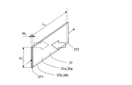
以下、図面を参照しながら本発明の実施形態のボンディング装置用ヒータについて説明する。図1に示すように、本実施形態のボンディング装置用ヒータ30は、平板形の本体31と、ボンディングツール40が取り付けられる第一の面である下面31bと、断熱材20が取り付けられる第二の面である上面31aとを備えている。上面31aの中央近傍には略直方体の窪み34が設けられ、本体31には窪み34から側面33に延びる多数の毛細スリット35が設けられている。この窪み34と上面31aに合わせられる断熱材20の合わせ面21とは、冷却空気が流入するキャビティ36を形成し、多数の毛細スリット35と上面31aに取り付けられる断熱材20の合わせ面21とは、キャビティ36から側面33に延びる多数の毛細冷却流路37を形成している。
Hereinafter, a bonding apparatus heater according to an embodiment of the present invention will be described with reference to the drawings. As shown in FIG. 1, the
断熱材20の上部には、ステンレス製のベース部材10が取り付けられており、このベース部材10は、図示しないボンディング装置のボンディングヘッドに取り付けられ、ボンディングヘッドに内蔵されている上下方向の駆動装置によりベース部材10と断熱材20とボンディング装置用ヒータ30とボンディングツール40とが一体となって上下方向に移動する。
A stainless
ボンディング装置用ヒータ30は、例えば、窒化アルミなどのセラミックスの内部に白金あるいはタングステンなどにより構成された発熱抵抗体を埋め込んだものである。また、断熱材20は、ボンディング装置用ヒータ30の熱をベース部材10に伝えないようにするもので、例えば、アドセラム(登録商標)等のセラミックス製である。
The
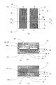
図2を参照しながらボンディング装置用ヒータ30と断熱材20の構造について詳細に説明する。図2(a)は、ボンディング装置用ヒータ30の上面31aを示す平面図であり、図2(b)は図2(a)に示すA−Aの断面図であり、図2(c)は図2(a)に示すB−Bの断面図である。
The structures of the
図2(a)に示すように、ボンディング装置用ヒータ30の上面31aの上下方向の中央部には、2つの窪み34が設けられており、各窪み34の上下方向の壁面から各側面33に向かって本体31の中に多数の毛細スリット35が延びている。本実施形態のボンディング装置用ヒータ30では、各窪み34の各上下方向の壁から本体31の上下方向の各側面33に向かってそれぞれ63本の毛細スリット35が延びている。従って、図2(a)に示す上面31aには、合計63×2×2=252本の毛細スリット35が形成されている。また、各毛細スリット35の長さはL1である。毛細スリット35は、例えば、ダイシング装置によって切削することによって形成してもよい。
As shown in FIG. 2 (a), two
図3に示すように各毛細スリット35の幅W1は0.05mm、毛細スリット35の間の壁38の厚さD1は0.1mm、毛細スリット35の深さH1は、0.3mmである。このように、毛細スリット35は、幅W1が深さH1よりも小さく、本実施形態では、幅W1に対する深さH1の比率(深さH1/幅W1)=(0.3/0.05)=6.0となっている。また、窪み34の深さは毛細スリット35と同様の0.3mmの深さとなっている。
As shown in FIG. 3, the width W 1 of each capillary slit 35 is 0.05 mm, the thickness D 1 of the
図2(b)、図2(c)に示すように、本体31の上面31aには断熱材20が重ねあわされている。断熱材20の合わせ面21は平面であり、上面31aに設けられた窪み34、毛細スリット35の周囲の面と密着している。このため、図2(b)に示すように、本体31の上面31aに断熱材20の合わせ面21が重ねあわされると、略直方体の窪み34の上側の解放面及び毛細スリット35の上側の解放面が閉じられ、各窪み34と合わせ面21とは略直方体の各キャビティ36を形成する。同様に図2(c)に示すように、多数の毛細スリット35と合わせ面21は、上下方向に細長い多数の毛細冷却流路37を形成する。また、図2(b)に示すように、断熱材20には、各キャビティ36にそれぞれ連通する2つの冷却空気孔25が設けられている。そして、各冷却空気孔25に供給された冷却空気は、図2(b)の下向き矢印で示すように、冷却空気孔25からキャビティ36に流入した後、各キャビティ36から多数の毛細冷却流路37に流入し、図2(a)に示す上下方向の矢印ように、各側面33側から外部に流出し、ボンディング装置用ヒータ30を冷却する。
As shown in FIGS. 2B and 2C, the
図4に示すように、本実施形態のボンディング装置用ヒータ30の毛細冷却流路37は、幅W1、深さH1、長さL1の矩形断面の流路であり、冷却空気は、キャビティ36に連通している入口371から流路に入り、側面33の上にある出口372から流出する。毛細冷却流路37の幅W1は0.05mmと非常に狭くなっている一方、その深さH1は0.3mmと幅W1の6倍にもなっていることから、毛細冷却流路37の中を流れる空気の流れは狭い平行平板間の流れとなり、ボンディング装置用ヒータ30の本体31と空気との熱交換は毛細冷却流路37の両側面37aを構成する毛細スリット35の両側面35aが支配的で毛細冷却流路37の底面37bを構成する毛細スリット35の底面35bはほとんど熱交換に寄与しなくなる。本実施形態のボンディング装置用ヒータ30では毛細冷却流路37の数は252であることから、有効熱交換面積は、次のようになる。
As shown in FIG. 4, the capillary
有効熱交換面積
=毛細スリット35の両側面35aの面積=H1×L1×2×毛細冷却流路37の数
=H1×L1×504
となる。
Effective heat exchange area = area of both
= H 1 × L 1 × 504
It becomes.
また、毛細冷却流路37の全流路断面積は、
全流路断面積
=W1×H1×毛細冷却流路37の数=W1×H1×504
となる。
In addition, the total channel cross-sectional area of the
Total channel cross-sectional area = W 1 × H 1 × number of
It becomes.
一方、図5に示すように、断熱材20の合わせ面21に本実施形態の毛細冷却流路37の全流路断面積と同様の断面積を持つ冷却空気流路26を形成した場合を考える。図5に示す例では、冷却空気流路26は、図中の横方向には仕切りが無い流路として形成されている。この場合、2つの毛細冷却流路37の幅W1と壁38の厚さD1の合計長さ、すなわち毛細冷却流路37の2ピッチ分の幅W2は、(0.05+0.1)×2=0.3mmで毛細冷却流路37の深さH1と同様であることから、冷却空気流路26の高さH2を毛細冷却流路37の幅W1の2倍の0.1mmとすれば、両者の流路断面積は同一となる。そして、図5に示す幅W2の冷却空気流路26の有効熱交換領域は冷却空気流路26の上面31aに面する底面26bのみであり、側面26aはほとんど熱交換に寄与しないから、有効熱交換面積は、W2×L1であるのに対し、幅W2の部分の毛細冷却流路37の有効熱交換面積は、H1×L1×2(両面)×2(2流路)となる。ここで、W2=H1であることから、幅W2の部分の毛細冷却流路37の有効熱交換面積は、幅W2の冷却空気流路26の有効熱交換面積の4倍となることとなる。
On the other hand, as shown in FIG. 5, a case is considered in which a cooling
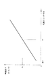
また、毛細冷却流路37を構成する毛細スリット35の両側面35aの各表面から冷却空気への熱伝達は、流れに垂直な方向の熱伝導が支配的で、乱流のような物資移動を伴う熱移動は非常に小さくなる。このため、図6に示すように、熱移動の際の熱抵抗は毛細スリット35の幅Wの大きさが大きくなると増大する。
In addition, the heat transfer from each
従って、図1から図4を参照して説明した本実施形態のボンディング装置用ヒータ30の毛細冷却流路37は、図5を参照して説明した従来技術による冷却空気流路26の4倍の有効熱交換面積を有し、冷却空気流路26よりも熱抵抗が少ないことから、より大きな熱交換を行うことができ、より効果的にボンディング装置用ヒータ30を冷却することができる。
Accordingly, the capillary
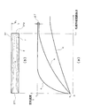
図7に示す様に、本実施形態のボンディング装置用ヒータ30の毛細冷却流路37の内部の温度は、毛細冷却流路37の流れ方向の位置と空気の流量によって変化する。図7(a)は、毛細冷却流路37の幅方向中央の長手方向距離に対する空気温度の変化を示すグラフであり、図7(b)は毛細冷却流路37中の空気温度が壁面(毛細スリット35の壁面)の温度T2となる位置を示す図である。空気流量が少ない場合には、図7(a)の線a、図7(b)の線pに示す様に、毛細冷却流路37の入口371に温度T1で流入した空気の温度は急速に上昇し、流路の前半で毛細冷却流路37の壁面(毛細スリット35の壁面)の温度T2まで上昇してしまい、そのまま出口372から流出する。この場合、流路の後半では空気温度が壁面の温度T2に達してしまっているので、本体31から熱を奪うことができなくなってしまい、冷却能力が十分に発揮できていない。
As shown in FIG. 7, the temperature inside the
逆に、流量が多い場合には、図7(a)の線c、図7(b)の線rに示す様に、入口371に温度T1で流入した空気は、温度が壁面の温度T2の半分程度の温度で出口372から外部に流出していく。この場合、毛細冷却流路37の長手方向全般に渡って空気と壁面(毛細スリット35の壁面)との温度差が大きいので、冷却能力は大きくなるが、冷却空気流量のわりに冷却能力は大きくならない。
On the other hand, when the flow rate is large, as shown by the line c in FIG. 7A and the line r in FIG. 7B, the air flowing into the
そこで、本実施形態のボンディング装置用ヒータ30では、毛細冷却流路37の出口372から流出する空気の温度が壁面(毛細スリット35の壁面)の温度T2よりも少しだけ、あるいは所定の閾値ΔTだけ低い温度となるように空気流量を調整する。この流量は、試験などによって予め決めておき、その流量となるように冷却空気孔25に供給する空気の圧力を調整したり、冷却空気孔25の入り口側に設けた流量調節弁あるいはレギュレータによって流量を調節したりするようにしてもよい。このように冷却空気流量を調整することによって少ない冷却空気流量で効果的にボンディング装置用ヒータ30を冷却することができる。
Therefore, in the
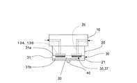
図8から図9を参照して本発明の他の実施形態について説明する。先に図1から図7を参照して説明した実施形態と同様の部分には同様の符号を付して説明は省略する。図8に示すように、本実施形態では、断熱材20の合わせ面21の中央近傍に第二の窪みである窪み134が設けられ、図9(a)に示す様に、本体31に設けられた毛細スリット35は、一方の側面33から対抗する他方の側面33まで延びている。窪み134には、冷却空気孔25が接続されている。毛細スリット35の本数、幅、深さは先に図1から7を参照して説明した実施形態と同様である。
Another embodiment of the present invention will be described with reference to FIGS. Parts similar to those of the embodiment described above with reference to FIGS. 1 to 7 are denoted by the same reference numerals and description thereof is omitted. As shown in FIG. 8, in this embodiment, a
図8、図9(b)に示す様に、断熱材20の合わせ面21を本体31の上面31aに合わせると、断熱材20の合わせ面21に設けられた窪み134は、本体31の上面31aの毛細スリット35が設けられていない面に密着し、冷却空気孔25からの空気が入り込むキャビティ136を構成する。図9(c)に示すように、スリット35と断熱材20の合わせ面21とは毛細冷却流路37を構成する。図9(a)に示す様に、毛細冷却流路37の長さはL1である。また、図9(b)に示す様に、キャビティ136の下面は多数のスリット35の上側の開放端と連通している。そして、冷却空気孔25からキャビティ136に入った空気は、キャビティ136から下側のスリット35に流入した後、図9(a)に示すように、毛細冷却流路37を側面33に向って流れ、ボンディング装置用ヒータ30を冷却する。
As shown in FIG. 8 and FIG. 9B, when the
本実施形態は、先に図1から図7を参照して説明した実施形態と同様の効果に加え、セラミックス製の本体31の加工が簡単であり、より簡便な構成とすることができるという効果を奏する。
In the present embodiment, in addition to the same effects as those of the embodiment described above with reference to FIGS. 1 to 7, the processing of the ceramic
以上説明した実施形態では、毛細スリット35の幅W1は0.05mmとして説明したが、毛細スリット35の幅W1は0.5mm〜0.01mmの範囲であれば自由に選択してもよい。0.1mm〜0.02mmの範囲であればより好ましく、0.05mm〜0.02mmの範囲であれば更に好ましい。また、毛細スリット35の深さH1は、0.3mm、毛細スリット35の幅W1と毛細スリット35の深さH1の比率は1:6として説明したが、毛細スリット35の深さH1は毛細スリット35の幅W1よりも深ければよく、例えば、1.0mm〜0.1mmの範囲で自由に選択してもよい。また、毛細スリット35の幅W1と毛細スリット35の深さH1の比率は1:6に限られず、1:3〜1:10の範囲であれば自由に選択できる。 In the embodiment described above, the width W 1 of the capillary slit 35 is described as 0.05 mm. However, the width W 1 of the capillary slit 35 may be freely selected as long as it is in the range of 0.5 mm to 0.01 mm. . A range of 0.1 mm to 0.02 mm is more preferable, and a range of 0.05 mm to 0.02 mm is more preferable. The depth H 1 of the capillary slit 35 is 0.3 mm, and the ratio of the width W 1 of the capillary slit 35 to the depth H 1 of the capillary slit 35 is 1: 6. However, the depth H 1 of the capillary slit 35 is described. 1 may be deeper than the width W 1 of the capillary slit 35, and may be freely selected within a range of 1.0 mm to 0.1 mm, for example. Further, the ratio of the width W 1 of the capillary slit 35 to the depth H 1 of the capillary slit 35 is not limited to 1: 6, and can be freely selected within a range of 1: 3 to 1:10.
10 ベース部材、20 断熱材、21 合わせ面、25 冷却空気孔、26 冷却空気流路、30 ボンディング装置用ヒータ、31 本体、31a 上面、31b 下面、33 側面、34,134 窪み、35 毛細スリット、35a,37a 側面、35b,37b 底面、36,136 キャビティ、37 毛細冷却流路、38 壁、40 ボンディングツール、371 入口、372 出口。 10 base member, 20 heat insulating material, 21 mating surface, 25 cooling air hole, 26 cooling air flow path, 30 heater for bonding device, 31 main body, 31a upper surface, 31b lower surface, 33 side surface, 34, 134 recess, 35 capillary slit, 35a, 37a side surface, 35b, 37b bottom surface, 36, 136 cavity, 37 capillary cooling channel, 38 walls, 40 bonding tool, 371 inlet, 372 outlet.
Claims (4)
前記第二の面に設けられ、前記第二の面に沿った方向の幅が前記第二の面に垂直方向の深さよりも小さい多数の毛細スリットと、を備え、
多数の前記毛細スリットと前記第二の面に取り付けられる前記断熱材の合わせ面とは、多数の毛細冷却流路を形成し、
前記毛細スリットの両側面の合計面積が、前記第二の面上で前記毛細スリットが形成されている領域の面積よりも大きく、
前記第二の面は、中央近傍に窪みが設けられ、
前記窪みと前記第二の面に取り付けられる前記断熱材の合わせ面とは、冷却空気が流入するキャビティを形成し、
多数の前記毛細スリットは、前記キャビティから側面に延びること、を特徴とするボンディング装置用ヒータ。 A flat plate type heater for a bonding apparatus having a first surface made of ceramics to which a bonding tool is attached and a second surface to which a heat insulating material is attached on the side opposite to the first surface,
A plurality of capillary slits provided on the second surface, the width in the direction along the second surface being smaller than the depth in the direction perpendicular to the second surface;
A number of the capillary slits and the mating surface of the heat insulating material attached to the second surface form a number of capillary cooling channels,
The total area of both sides of the capillary slits, much larger than the area of the second region in which the capillary slits on the surface is formed,
The second surface is provided with a depression near the center,
The mating surface of the heat insulating material attached to the recess and the second surface forms a cavity into which cooling air flows,
A large number of the capillary slits extend from the cavity to the side surface.
前記第二の面に設けられ、前記第二の面に沿った方向の幅が前記第二の面に垂直方向の深さよりも小さい多数の毛細スリットと、を備え、
多数の前記毛細スリットと前記第二の面に取り付けられる前記断熱材の合わせ面とは、多数の毛細冷却流路を形成し、
前記毛細スリットの両側面の合計面積が、前記第二の面上で前記毛細スリットが形成されている領域の面積よりも大きく、
前記断熱材は、前記合わせ面の中央近傍に第二の窪みが設けられ、
前記第二の窪みと前記第二の面とは、冷却空気が流入するキャビティを形成し、
多数の前記毛細スリットは、前記キャビティに連通し、対向する各側面の間に延びること、を特徴とするボンディング装置用ヒータ。 A flat plate type heater for a bonding apparatus having a first surface made of ceramics to which a bonding tool is attached and a second surface to which a heat insulating material is attached on the side opposite to the first surface,
A plurality of capillary slits provided on the second surface, the width in the direction along the second surface being smaller than the depth in the direction perpendicular to the second surface;
A number of the capillary slits and the mating surface of the heat insulating material attached to the second surface form a number of capillary cooling channels,
The total area of both sides of the capillary slits, much larger than the area of the second region in which the capillary slits on the surface is formed,
The heat insulating material is provided with a second depression near the center of the mating surface,
The second depression and the second surface form a cavity into which cooling air flows,
A large number of the capillary slits communicate with the cavity and extend between the opposing side surfaces .
冷却空気流量は、前記毛細冷却流路出口の毛細スリット中央の冷却空気温度が前記毛細スリットの表面温度よりも所定の閾値だけ低い温度となる流量であること、
を特徴とする冷却方法。 A flat plate shape having a first surface made of ceramics to which a bonding tool is attached and a second surface to which a heat insulating material is attached on the side opposite to the first surface, provided on the second surface, A plurality of capillary slits whose width in the direction along the second surface is smaller than the depth in the direction perpendicular to the second surface, and the heat insulating material attached to the plurality of capillary slits and the second surface the mating surface, forming a plurality of capillary cooling channel, the total area of both sides of the capillary slits, much larger than the area of the second region in which the capillary slits on the surface is formed, the The second surface is provided with a recess in the vicinity of the center, and the recess and the mating surface of the heat insulating material attached to the second surface form a cavity into which cooling air flows, and the plurality of capillary slits , Side from the cavity A bonding apparatus for heater cooling method extending,
The cooling air flow rate is a flow rate at which the cooling air temperature at the center of the capillary slit at the outlet of the capillary cooling channel is lower than the surface temperature of the capillary slit by a predetermined threshold,
A cooling method characterized by the above.
冷却空気流量は、前記毛細冷却流路出口の毛細スリット中央の冷却空気温度が前記毛細スリットの表面温度よりも所定の閾値だけ低い温度となる流量であること、
を特徴とする冷却方法。 A flat plate shape having a first surface made of ceramics to which a bonding tool is attached and a second surface to which a heat insulating material is attached on the side opposite to the first surface, provided on the second surface, A plurality of capillary slits whose width in the direction along the second surface is smaller than the depth in the direction perpendicular to the second surface, and the heat insulating material attached to the plurality of capillary slits and the second surface the mating surface, forming a plurality of capillary cooling channel, the total area of both sides of the capillary slits, much larger than the area of the second region in which the capillary slits on the surface is formed, the The heat insulating material is provided with a second recess near the center of the mating surface, the second recess and the second surface form a cavity into which cooling air flows, and the plurality of capillary slits are Communicates with and faces the cavity A bonding apparatus for heater cooling method that extends between the side surfaces,
The cooling air flow rate is a flow rate at which the cooling air temperature at the center of the capillary slit at the outlet of the capillary cooling channel is lower than the surface temperature of the capillary slit by a predetermined threshold,
A cooling method characterized by the above.
Priority Applications (9)
| Application Number | Priority Date | Filing Date | Title |
|---|---|---|---|
| JP2012161304A JP5793473B2 (en) | 2012-07-20 | 2012-07-20 | Heater for bonding apparatus and cooling method thereof |
| TW104117385A TW201535635A (en) | 2012-07-20 | 2013-02-25 | Heater for joint device and cooling method thereof |
| TW102106499A TWI489598B (en) | 2012-07-20 | 2013-02-25 | A heater for a bonding device and a cooling method thereof |
| PCT/JP2013/060908 WO2014013764A1 (en) | 2012-07-20 | 2013-04-11 | Heater for bonding device and method for cooling same |
| KR1020157017088A KR20150082673A (en) | 2012-07-20 | 2013-04-11 | Heater for bonding device and method for cooling same |
| CN201380014787.0A CN104520980B (en) | 2012-07-20 | 2013-04-11 | Engagement device heater and its cooling means |
| KR1020147024142A KR101559741B1 (en) | 2012-07-20 | 2013-04-11 | Heater for bonding device and method for cooling same |
| SG11201500238RA SG11201500238RA (en) | 2012-07-20 | 2013-04-11 | Heater for bonding apparatus and method of cooling the same |
| US14/597,635 US10350692B2 (en) | 2012-07-20 | 2015-01-15 | Heater for bonding apparatus and method of cooling the same |
Applications Claiming Priority (1)
| Application Number | Priority Date | Filing Date | Title |
|---|---|---|---|
| JP2012161304A JP5793473B2 (en) | 2012-07-20 | 2012-07-20 | Heater for bonding apparatus and cooling method thereof |
Related Child Applications (2)
| Application Number | Title | Priority Date | Filing Date |
|---|---|---|---|
| JP2015050779A Division JP2015109485A (en) | 2015-03-13 | 2015-03-13 | Heater for bonding apparatus and method for cooling the same |
| JP2015127628A Division JP6149241B2 (en) | 2015-06-25 | 2015-06-25 | Heater for bonding apparatus and cooling method thereof |
Publications (3)
| Publication Number | Publication Date |
|---|---|
| JP2014022629A JP2014022629A (en) | 2014-02-03 |
| JP2014022629A5 JP2014022629A5 (en) | 2014-10-23 |
| JP5793473B2 true JP5793473B2 (en) | 2015-10-14 |
Family
ID=49948601
Family Applications (1)
| Application Number | Title | Priority Date | Filing Date |
|---|---|---|---|
| JP2012161304A Active JP5793473B2 (en) | 2012-07-20 | 2012-07-20 | Heater for bonding apparatus and cooling method thereof |
Country Status (7)
| Country | Link |
|---|---|
| US (1) | US10350692B2 (en) |
| JP (1) | JP5793473B2 (en) |
| KR (2) | KR101559741B1 (en) |
| CN (1) | CN104520980B (en) |
| SG (1) | SG11201500238RA (en) |
| TW (2) | TWI489598B (en) |
| WO (1) | WO2014013764A1 (en) |
Families Citing this family (18)
| Publication number | Priority date | Publication date | Assignee | Title |
|---|---|---|---|---|
| US9093549B2 (en) * | 2013-07-02 | 2015-07-28 | Kulicke And Soffa Industries, Inc. | Bond heads for thermocompression bonders, thermocompression bonders, and methods of operating the same |
| US9659902B2 (en) * | 2014-02-28 | 2017-05-23 | Kulicke And Soffa Industries, Inc. | Thermocompression bonding systems and methods of operating the same |
| JP6176542B2 (en) * | 2015-04-22 | 2017-08-09 | パナソニックIpマネジメント株式会社 | Electronic component bonding head |
| JP6529865B2 (en) * | 2015-08-31 | 2019-06-12 | 株式会社イチネンジコー | heater |
| JP6457905B2 (en) * | 2015-08-31 | 2019-01-23 | 株式会社イチネンジコー | heater |
| JP6632856B2 (en) * | 2015-10-16 | 2020-01-22 | 東レエンジニアリング株式会社 | Bonding head and mounting equipment |
| JP6836317B2 (en) * | 2015-10-16 | 2021-02-24 | 東レエンジニアリング株式会社 | Bonding head and mounting device |
| TWI662671B (en) * | 2016-03-24 | 2019-06-11 | Shinkawa Ltd. | Joining device |
| CN107825011A (en) * | 2017-11-10 | 2018-03-23 | 普尔思(苏州)无线通讯产品有限公司 | A kind of welding system that can control temperature |
| JP6680930B2 (en) * | 2019-05-15 | 2020-04-15 | 株式会社イチネンジコー | heater |
| JP6850854B2 (en) * | 2019-11-18 | 2021-03-31 | 東レエンジニアリング株式会社 | Bonding head and mounting device |
| TWI834007B (en) | 2019-11-19 | 2024-03-01 | 日商新川股份有限公司 | Semiconductor device manufacturing apparatus and manufacturing method |
| JP7268929B2 (en) | 2020-08-05 | 2023-05-08 | 株式会社新川 | Mounting device and mounting method |
| KR102604789B1 (en) * | 2020-11-30 | 2023-11-21 | 세메스 주식회사 | Heater assembly and bonding head including same |
| CN114981939B (en) * | 2020-12-28 | 2026-01-30 | 雅马哈智能机器株式会社 | Mounting head |
| TWI791287B (en) * | 2021-09-16 | 2023-02-01 | 日商新川股份有限公司 | Packaging device and packaging method |
| TWI876430B (en) * | 2023-07-19 | 2025-03-11 | 日月光半導體製造股份有限公司 | Thermal compression apparatus |
| US20250326073A1 (en) * | 2024-04-23 | 2025-10-23 | Asmpt Singapore Pte. Ltd. | Bond head heater incorporating fluid chamber for cooling |
Family Cites Families (20)
| Publication number | Priority date | Publication date | Assignee | Title |
|---|---|---|---|---|
| US5592363A (en) | 1992-09-30 | 1997-01-07 | Hitachi, Ltd. | Electronic apparatus |
| US5453641A (en) * | 1992-12-16 | 1995-09-26 | Sdl, Inc. | Waste heat removal system |
| JP3255871B2 (en) * | 1997-03-31 | 2002-02-12 | 住友大阪セメント株式会社 | Manufacturing method of pulse heater and semiconductor chip mounting board |
| JPH11204994A (en) | 1998-01-14 | 1999-07-30 | Hitachi Ltd | Device mounting device |
| JP2000277567A (en) * | 1999-03-25 | 2000-10-06 | Ngk Insulators Ltd | Bonding heater |
| JP2002016091A (en) | 2000-06-29 | 2002-01-18 | Kyocera Corp | Contact heating device |
| US6414271B2 (en) | 2000-05-25 | 2002-07-02 | Kyocera Corporation | Contact heating device |
| JP2002076102A (en) * | 2000-08-31 | 2002-03-15 | Ibiden Co Ltd | Ceramic substrate |
| JP3801966B2 (en) * | 2002-07-31 | 2006-07-26 | 京セラ株式会社 | Heating device |
| JP2007180505A (en) | 2005-12-02 | 2007-07-12 | Matsushita Electric Ind Co Ltd | Electronic component cooling system |
| US20070125526A1 (en) | 2005-12-02 | 2007-06-07 | Matsushita Electric Industrial Co., Ltd. | Cooling device for electronic components |
| US20070131659A1 (en) | 2005-12-09 | 2007-06-14 | Durocher Kevin M | Method of making an electronic device cooling system |
| JP4640170B2 (en) * | 2005-12-28 | 2011-03-02 | 株式会社豊田自動織機 | Soldering method, semiconductor module manufacturing method, and soldering apparatus |
| JP2007242724A (en) * | 2006-03-06 | 2007-09-20 | Seiko Epson Corp | Microchannel structure, method of manufacturing microchannel structure, and electronic apparatus |
| JP2007329306A (en) * | 2006-06-08 | 2007-12-20 | Matsushita Electric Ind Co Ltd | Thermocompression bonding equipment |
| EP2432012A4 (en) * | 2009-05-11 | 2014-04-16 | Toyota Motor Co Ltd | HEAT EXCHANGER, SEMICONDUCTOR DEVICE, METHOD FOR MANUFACTURING THE HEAT EXCHANGER, AND METHOD FOR MANUFACTURING THE SEMICONDUCTOR DEVICE |
| US8637794B2 (en) * | 2009-10-21 | 2014-01-28 | Lam Research Corporation | Heating plate with planar heating zones for semiconductor processing |
| JP4808283B1 (en) * | 2010-06-30 | 2011-11-02 | 株式会社新川 | Electronic component mounting apparatus and electronic component mounting method |
| US8633423B2 (en) * | 2010-10-14 | 2014-01-21 | Applied Materials, Inc. | Methods and apparatus for controlling substrate temperature in a process chamber |
| WO2013095362A1 (en) * | 2011-12-20 | 2013-06-27 | Intel Corporation | High performance transient uniform cooling solution for thermal compression bonding process |
-
2012
- 2012-07-20 JP JP2012161304A patent/JP5793473B2/en active Active
-
2013
- 2013-02-25 TW TW102106499A patent/TWI489598B/en active
- 2013-02-25 TW TW104117385A patent/TW201535635A/en unknown
- 2013-04-11 WO PCT/JP2013/060908 patent/WO2014013764A1/en not_active Ceased
- 2013-04-11 KR KR1020147024142A patent/KR101559741B1/en active Active
- 2013-04-11 SG SG11201500238RA patent/SG11201500238RA/en unknown
- 2013-04-11 CN CN201380014787.0A patent/CN104520980B/en active Active
- 2013-04-11 KR KR1020157017088A patent/KR20150082673A/en not_active Ceased
-
2015
- 2015-01-15 US US14/597,635 patent/US10350692B2/en active Active
Also Published As
| Publication number | Publication date |
|---|---|
| KR20140128380A (en) | 2014-11-05 |
| JP2014022629A (en) | 2014-02-03 |
| TW201405731A (en) | 2014-02-01 |
| CN104520980B (en) | 2017-07-07 |
| KR101559741B1 (en) | 2015-10-13 |
| TW201535635A (en) | 2015-09-16 |
| TWI489598B (en) | 2015-06-21 |
| US20150183040A1 (en) | 2015-07-02 |
| US10350692B2 (en) | 2019-07-16 |
| CN104520980A (en) | 2015-04-15 |
| SG11201500238RA (en) | 2015-03-30 |
| KR20150082673A (en) | 2015-07-15 |
| WO2014013764A1 (en) | 2014-01-23 |
Similar Documents
| Publication | Publication Date | Title |
|---|---|---|
| JP5793473B2 (en) | Heater for bonding apparatus and cooling method thereof | |
| KR102228798B1 (en) | Bonding head with a heatable and coolable suction member | |
| CN109196629B (en) | Joining device | |
| CN110880484B (en) | Semiconductor devices | |
| US20100081191A1 (en) | Anisotropic heat spreader for use with a thermoelectric device | |
| US8938880B2 (en) | Method of manufacturing an integrated cold plate for electronics | |
| JP6047724B2 (en) | Heater for bonding apparatus, heater assembly for bonding apparatus, and bonding apparatus | |
| JP6893003B2 (en) | Cooler, semiconductor module | |
| TWI751971B (en) | Apparatus and method for semiconductor device test and semiconductor device test system | |
| JP6149241B2 (en) | Heater for bonding apparatus and cooling method thereof | |
| CN116613121A (en) | Semiconductor packaging structure and forming method thereof | |
| JP2015109485A (en) | Heater for bonding apparatus and method for cooling the same | |
| JP6850854B2 (en) | Bonding head and mounting device | |
| US10192847B2 (en) | Rapid cooling system for a bond head heater | |
| JP6836317B2 (en) | Bonding head and mounting device | |
| TWI743241B (en) | Fluxing systems, bonding machines including fluxing systems, and methods of operating the same | |
| JP6632856B2 (en) | Bonding head and mounting equipment |
Legal Events
| Date | Code | Title | Description |
|---|---|---|---|
| A621 | Written request for application examination |
Free format text: JAPANESE INTERMEDIATE CODE: A621 Effective date: 20140815 |
|
| A871 | Explanation of circumstances concerning accelerated examination |
Free format text: JAPANESE INTERMEDIATE CODE: A871 Effective date: 20140827 |
|
| A521 | Request for written amendment filed |
Free format text: JAPANESE INTERMEDIATE CODE: A523 Effective date: 20140909 |
|
| A975 | Report on accelerated examination |
Free format text: JAPANESE INTERMEDIATE CODE: A971005 Effective date: 20141010 |
|
| A131 | Notification of reasons for refusal |
Free format text: JAPANESE INTERMEDIATE CODE: A131 Effective date: 20141021 |
|
| A02 | Decision of refusal |
Free format text: JAPANESE INTERMEDIATE CODE: A02 Effective date: 20150203 |
|
| A521 | Request for written amendment filed |
Free format text: JAPANESE INTERMEDIATE CODE: A523 Effective date: 20150313 |
|
| A911 | Transfer to examiner for re-examination before appeal (zenchi) |
Free format text: JAPANESE INTERMEDIATE CODE: A911 Effective date: 20150326 |
|
| A912 | Re-examination (zenchi) completed and case transferred to appeal board |
Free format text: JAPANESE INTERMEDIATE CODE: A912 Effective date: 20150424 |
|
| A521 | Request for written amendment filed |
Free format text: JAPANESE INTERMEDIATE CODE: A523 Effective date: 20150625 |
|
| A61 | First payment of annual fees (during grant procedure) |
Free format text: JAPANESE INTERMEDIATE CODE: A61 Effective date: 20150810 |
|
| R150 | Certificate of patent or registration of utility model |
Ref document number: 5793473 Country of ref document: JP Free format text: JAPANESE INTERMEDIATE CODE: R150 |
|
| R250 | Receipt of annual fees |
Free format text: JAPANESE INTERMEDIATE CODE: R250 |
|
| R250 | Receipt of annual fees |
Free format text: JAPANESE INTERMEDIATE CODE: R250 |
|
| R250 | Receipt of annual fees |
Free format text: JAPANESE INTERMEDIATE CODE: R250 |
|
| S111 | Request for change of ownership or part of ownership |
Free format text: JAPANESE INTERMEDIATE CODE: R313111 |
|
| R350 | Written notification of registration of transfer |
Free format text: JAPANESE INTERMEDIATE CODE: R350 |