JP5836611B2 - Sorting device - Google Patents
Sorting device Download PDFInfo
- Publication number
- JP5836611B2 JP5836611B2 JP2011054573A JP2011054573A JP5836611B2 JP 5836611 B2 JP5836611 B2 JP 5836611B2 JP 2011054573 A JP2011054573 A JP 2011054573A JP 2011054573 A JP2011054573 A JP 2011054573A JP 5836611 B2 JP5836611 B2 JP 5836611B2
- Authority
- JP
- Japan
- Prior art keywords
- gate
- cylinder
- rod
- workpiece
- inner cover
- Prior art date
- Legal status (The legal status is an assumption and is not a legal conclusion. Google has not performed a legal analysis and makes no representation as to the accuracy of the status listed.)
- Active
Links
Images
Landscapes
- Discharge Of Articles From Conveyors (AREA)
- Special Conveying (AREA)
- Sorting Of Articles (AREA)
Description
本発明は、搬送装置で搬送されてきたワークをシリンダで搬送装置の外に押し出す選別装置に係り、特に作業者にとって安全性が高く、またシリンダが伸びている状態でワークが接触した場合の外力にも耐えられる十分な剛性を備えた選別装置に関するものである。 The present invention relates to a sorting device that pushes a workpiece conveyed by a conveying device out of the conveying device with a cylinder, and is particularly safe for an operator, and an external force when the workpiece contacts with the cylinder extended. The present invention relates to a sorting apparatus having sufficient rigidity to withstand.
下記特許文献1には、搬送コンベアで送り込まれてくるトレーを、空気シリンダで作動するプッシャー部材によって搬送台車上に移動させるトレー類の移載装置に関する発明が開示されている。この発明では、空気シリンダのロッドで押し出されるプッシャー部材は、案内部材に支持されたガイド棒に連結されており、プッシャー部材の押圧が確実となるように移動を補助されている。
特許文献1で例示したように、搬送手段によって送られてきたワークをシリンダのロッドの先端に設けた押圧板で押し出し、搬送手段外に送り出すタイプの選別装置では、搬送動作を行なう搬送手段や、往復動作するシリンダや押圧板等のように動作する部分が多く、その近傍で作業する作業者にとっては体の一部や衣服を挟まれる危険性があった。
As exemplified in
そこで安全のために、選別装置のシリンダ側をカバーで覆う工夫がなされることもあったが、シリンダのストロークが大きい場合はカバーから突出して移動する部分が長くなり、往復動作に要する時間も長くなるため、本体側に設けたカバーと、そこから突出したロッドや押圧板との間に作業者が指等を挟むおそれが大きくなり、必ずしも十分な安全性が達成されているとはいえない状況であった。 Therefore, for the sake of safety, there has been a device to cover the cylinder side of the sorting device with a cover, but when the cylinder stroke is large, the part that protrudes and moves from the cover becomes long, and the time required for the reciprocating operation is also long. Therefore, there is a greater risk that the operator may pinch fingers or the like between the cover provided on the main body side and the rod or pressing plate protruding from the cover, and it cannot be said that sufficient safety is necessarily achieved. Met.
また、シリンダのストロークが大きくロッドの突出長さが大きくなると、ワークを押圧して移動させる際に、ワークと押圧板の接触する位置によってはロッドや押圧板に加わるモーメントが大きくなり、ワークの押圧移動に支障を来す場合も考えられる。特に、搬送手段によるワークの搬送とシリンダによる押圧動作のタイミングに何らかの齟齬が生じ、ロッドが伸びている状態で搬送されてきたワークが押圧板の側面やロッドに当ってしまった場合には、ロッドに大きなモーメントが生じてしまい、装置が耐えられずに破壊・変形を生じてしまう恐れがあった。 If the stroke of the cylinder is large and the protruding length of the rod is large, when the workpiece is pressed and moved, the moment applied to the rod and the pressure plate will increase depending on the position where the workpiece and the pressure plate come into contact. It may be possible to hinder movement. In particular, if there is some wrinkle between the work transport by the transport means and the timing of the pressing operation by the cylinder, the work transported while the rod is extended will hit the side of the press plate or the rod. As a result, a large moment was generated, and the device could not withstand and could be destroyed or deformed.
本発明は、以上の課題に鑑みてなされたものであり、ワークを押し出すシリンダのストロークが大きい場合であっても、可動部分における挟み込み等の危険性が少ないために作業者の安全性が高く、またシリンダが伸びている状態でワークが接触した場合に生じうるモーメント等の外力にも耐えられる剛性の大きさを備えているため、容易には破壊・変形しない選別装置を提供することを目的としている。 The present invention has been made in view of the above problems, and even when the stroke of the cylinder that pushes out the workpiece is large, the safety of the operator is high because the danger of pinching in the movable part is small, It also has a rigidity that can withstand external forces such as moments that can occur when the workpiece comes into contact with the cylinder being extended, and therefore aims to provide a sorting device that does not easily break or deform. Yes.
請求項1に記載された選別装置1は、
搬送装置2で搬送されてきたワークWを搬送装置2の外に押し出す選別装置1において、
伸縮自在のロッド5を備え所定位置に固定されたシリンダ4と、
前記シリンダ4を内部に収納して所定位置に固定された外カバー8と、
所定位置に固定された一対の案内部材6と、
前記ロッド5の先端に固定され前記ロッド5が伸展した際にワークWを押し出すゲート9と、
前記ゲート9に取り付けられて前記ロッド5の伸縮に伴って前記外カバー8に対して出没する内カバー10と、
前記シリンダの両側に対称に配置されて前記ゲートと前記内カバーに両端部が固定され、前記ロッド5の伸縮に伴って前記ゲート9と前記内カバー10が移動する際に前記案内部材6に対して摺動自在に案内される一対のガイド部材7と、
を有することを特徴としている。
The
In the
A cylinder 4 provided with a
An
A pair of
A
An
Both ends of the cylinder are symmetrically arranged, and both ends are fixed to the gate and the inner cover, and the
It is characterized by having.
請求項1に記載された選別装置1によれば、選別作業時には、シリンダ4が作動してロッド5が伸展し、ゲート9が進んでワークWを搬送手段2から外に押し出し、その後ロッド5が縮退してゲート9は元の位置に戻る。この動作中、ゲート9に取り付けられた内カバー10は、ロッド5の伸縮に伴って外カバー8に対して出没するので、作業者がシリンダ4のロッド5やゲート9と本体側の外カバー8との間に指等を挟む危険性は少ない。また、ワークWを押圧するゲート9は、シリンダ4のロッド5だけで支えられているのではなく、ゲート9には内カバー10が固定されると共に、さらに、シリンダ4の両側に対称に配置された一対のガイド部材7がゲート9と内カバー10を連結しており、ゲート9と内カバー10とガイド部材7は全体として一体に構成されている。そして所定位置に固定された一対の案内部材6に対して一対のガイド部材7が案内されることで、これらゲート9等が一体となってシリンダ4の駆動により往復動作するようになっている。従って、押圧時にゲート9にワークWから大きなモーメントが加わった場合にも、選別装置1として耐えられるだけの剛性が実現されている。
According to the
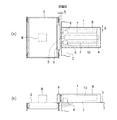
図1及び図2を参照して実施形態の選別装置1について説明する。この選別装置1は、搬送装置であるベルトコンベア2で搬送されてきたワークWを、ベルト上で搬送方向とは直交する方向に押圧して移動させ、ベルトコンベア2の搬送面から外に押し出す装置である。
The
図示しない基台に取り付けられたベルトコンベア2の一側方には、本装置の基台となるフレーム3が搬送方向と平行に配置されている。フレーム3の上面には、搬送方向と直交する向きでシリンダ4が固定されている。シリンダ4は伸縮自在のロッド5を備えている。待機時の位置(引き込み位置)では、ロッド5の先端はベルトコンベア2の搬送面の外側にある。このようなシリンダ4としては、作動原理は問わず、油圧又は空圧の駆動シリンダでもよいし、電気で作動するソレノイドでもよく、要するにワークWの押圧のために必要な力でロッド5を自在に往復動作できるものであればよい。
なお、以下に続く本実施形態の説明においては、シリンダ4を基準とすれば、ロッド5が出没する側(図1において相対的に左方)を装置全体としての前方と考え、ロッド5が出没する側と反対側(図1において相対的に右方)を同後方と考え、係る見方を本装置における前後についての基準として、本実施形態の装置の構成、部品等の配置、部品等の位置関係等の説明において適用するものとする。
On one side of the
In the following description of the present embodiment, if the cylinder 4 is used as a reference, the side on which the
フレーム3の上面において、平面視でシリンダ4を中心とする対称な2つの位置であって、シリンダ4の前端部に近い各位置には、案内部材6がそれぞれ固定されている。この案内部材6は、後述する丸棒状のガイド部材7を軸方向に往復自在に案内するものであり、その案内方向はシリンダ4のロッド5が往復動作する方向と同一である。
On the upper surface of the
フレーム3の上面には、シリンダ4及び案内部材6を内部に収納するように外カバー8が被せられ、フレーム3に固定されている。この外カバー8は、概ね直方体状の箱型であり、その下面と前面は開放されている。
An
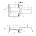
シリンダ4のロッド5の先端にはゲート9が固定されている。ゲート9は、シリンダ4の軸方向とは直交する水平方向に長い略直方体状の部材であり、その中央部の後面側においてロッド5に連結されている。図1(a)に示すように、ワークWに接触するゲート9の前面は、待機時の位置(引き込み位置)において、ベルトコンベア2の搬送面の外側であって、ベルトの端縁にほぼ一致した位置に配置されている。そして、この位置でワークWの搬送を待ち、ベルトコンベア2がワークWを搬送してきたら、所定のタイミングで駆動されたシリンダ4によって搬送面上に移動し、図2に示す排出動作時の位置(押し出し位置)まで進んでワークWをベルトから外に押し出す。この時、図2(b)に示すように、ゲート9の下端面とベルトコンベア2の搬送面との間には、ワークWや作業者の指等を巻き込むことはないが、ベルトとの過剰な摩擦や干渉を避けることができる程度の若干の隙間が生じるようになっている。そして、押し出し動作後、シリンダ4は逆方向に動作し、ゲート9は図1に示す待機時の位置に戻る。
A
ゲート9の後面側、すなわちワークWと接触する前面とは反対側の面には、内カバー10が取り付けられている。内カバー10は、外カバー8よりもやや小さい概ね直方体状の箱型であり、その下面は開放されており、シリンダ4や案内部材6と干渉せず重量も軽減されている。図1(a)に示すように、待機時の位置では、内カバー10は外カバー8の中に完全に収納されてしまうことはなく、適当な寸法Aだけ外カバー8の外に突出しており、外カバー8の前端面、すなわちゲート9の前記後面と対面する側の端面と、ゲート9の後面との間に作業者が指等を挟みにくい構造になっている。また、内カバー10の移動方向と直交する方向についての内外カバー10,8の隙間Bも十分な狭さ(例えば5mm程度以下)に設定されており、内外カバー10,8の間に作業者が指等を挟みにくい構造になっている。また、図2(b)に示すように、排出動作時の位置において、内カバー10の下端面とベルトコンベア2の搬送面との間には、ゲート9と搬送面の間隔よりも大きい隙間が生じるようになっており、ベルトとの過剰な摩擦や干渉を避けることができる。この部分は、ゲート9とベルトの隙間ほど作業者が指等を挟むことが少ない部分であるため、このような寸法としても問題は少ない。上述したワークWの排出動作時にシリンダ4を駆動してゲート9を往復して移動させると、内カバー10はゲート9と共に移動し、上述したような安全な隙間寸法をもって外カバー8に対して出没することができる。
An
ゲート9と内カバー10の上記往復動作は、固定部材である前記案内部材6と、これに摺動自在に挿通されたガイド部材7によって案内されている。ガイド部材7は丸棒状の部材であり、本実施形態では2本1組で用いられている。これら2本のガイド部材7は、平面視でロッド5及びシリンダ4を中心として対称となるように、かつロッド5の移動方向と平行に配置されている。そして、各ガイド部材7の前端部、すなわちゲート10に近い側の端部は、ゲート9の後面にロッド5を中心とする対称な位置にそれぞれ連結されており、また各ガイド部材7の後端部、すなわちゲート10から遠い側の端部は、内カバー10の後面にシリンダ4を中心とする対称な位置にそれぞれ連結されている。
The reciprocating motion of the
以上説明した実施形態の選別装置1によれば、選別作業時には、シリンダ4が作動してロッド5が伸展し、図1に示す待機時の位置から、図2に示す排出動作時の位置へ移動し、ワークWを排出した後に、再度図1に示す待機時の位置に戻る。すなわち、シリンダ4のロッド5の伸展に伴い、ベルトコンベア2の搬送方向と直交する方向にゲート9が進んでワークWを搬送面から外に押し出し、その後ロッド5が縮退してゲート9は元の位置に戻る。
According to the
この動作中、ゲート9に取り付けられた内カバー10は、ロッド5及びガイド部材7を覆った状態で、ロッド5の伸縮に伴い外カバー8に対して安全な設定隙間を維持しつつ出没する。従って、作業者がシリンダ4のロッド5やガイド部材7に触れ得る状況が全く生じないのはもちろん、ゲート9と外カバー8の前端面との間や、内外カバー10,8の隙間等に作業者が指等を挟む危険性も少ない。
During this operation, the
また、ワークWを押圧するゲート9は、シリンダ4のロッド5だけで支えられているのではなく、ゲート9には内カバー10が固定されると共に、さらにゲート9と内カバー10をガイド部材7が連結しており、板状のゲート9と箱状の内カバー10と一対の棒状のガイド部材7が全体として一体に構成されて高い剛性の構造体を実現している。特に、ゲート9の移動を案内する2本のガイド部材7の各後端部(ゲート10と反対側の端部)は、単なる板材で連結するのとは異なり、強度の高い面構造である箱状の内カバー10の後面に連結して一体化したので、前記構造体としての剛性は非常に高い。そしてフレーム3に固定された一対の案内部材6に対して、シリンダ4の両側に対称に配置された一対のガイド部材7が案内されることで、ゲート9を含む前記構造体が一体となってシリンダ4の駆動により往復動作することができる。従って、仮に、押圧時にゲート9にワークWから大きなモーメントが加わった場合や、シリンダ4のロッド5が伸展している状態でゲート9や内カバー10の側面にワークWが当って大きなモーメントが発生した場合であっても、装置が損傷・変形するおそれは少なく、選別装置1として大きな剛性が実現されている。
The
以上の各実施形態の説明では、案内部材6とガイド部材7の組がシリンダ4を中心として対称な配置で一対設けられていたが、必ずしも一対でなく、1組だけでも相応の案内効果による剛性は得られるし、3組以上設ければより高い案内効果によるより高い剛性が得られる。
In the description of each of the above embodiments, a pair of the
また、以上説明した実施形態では、図2(b)を参照して説明したように、排出動作時の位置において、内カバー10の下端面とベルトコンベア2の搬送面との隙間を、ゲート9とベルトの間隔よりも大きくしていたが、ゲート9の下端面と内カバー10の下端面を実質的に一致させ、各下端面がベルトと過剰に摩擦・干渉しない程度にベルトコンベア2の搬送面と接するように構成してもよい。このようにすれば、選別装置1の移動する部分と搬送面との間に作業者が指等を挟む危険性がさらに一層少なくなる。
In the embodiment described above, as described with reference to FIG. 2B, the gap between the lower end surface of the
1…選別装置
2…搬送装置としてのベルトコンベア
4…シリンダ
5…シリンダのロッド
6…案内部材
7…ガイド部材
8…外カバー
9…ゲート
10…内カバー
W…ワーク
DESCRIPTION OF
Claims (1)
伸縮自在のロッド(5)を備え所定位置に固定されたシリンダ(4)と、
前記シリンダを内部に収納して所定位置に固定された外カバー(8)と、
所定位置に固定された一対の案内部材(6)と、
前記ロッドの先端に固定され前記ロッドが伸展した際にワークを押し出すゲート(9)と、
前記ゲートに取り付けられて前記ロッドの伸縮に伴って前記外カバーに対して出没する内カバー(10)と、
前記シリンダの両側に対称に配置されて前記ゲートと前記内カバーに両端部が固定され、前記ロッドの伸縮に伴って前記ゲートと前記内カバーが移動する際に前記案内部材に対して摺動自在に案内される一対のガイド部材(7)と、
を有することを特徴とする選別装置(1)。 In the sorting device (1) for extruding the work (W) transported by the transport device (2) to the outside of the transport device,
A cylinder (4) provided with a telescopic rod (5) and fixed in place;
An outer cover (8) housed in the cylinder and fixed in place;
A pair of guide members (6) fixed in place;
A gate (9) that is fixed to the tip of the rod and pushes out the workpiece when the rod extends;
An inner cover (10) attached to the gate and extending and retracting with respect to the outer cover as the rod expands and contracts;
Symmetrically arranged on both sides of the cylinder, both ends are fixed to the gate and the inner cover, and slidable relative to the guide member when the gate and the inner cover move as the rod expands and contracts a pair of guide members guided in (7),
A sorting device (1) characterized by comprising:
Priority Applications (1)
| Application Number | Priority Date | Filing Date | Title |
|---|---|---|---|
| JP2011054573A JP5836611B2 (en) | 2011-03-11 | 2011-03-11 | Sorting device |
Applications Claiming Priority (1)
| Application Number | Priority Date | Filing Date | Title |
|---|---|---|---|
| JP2011054573A JP5836611B2 (en) | 2011-03-11 | 2011-03-11 | Sorting device |
Publications (2)
| Publication Number | Publication Date |
|---|---|
| JP2012188269A JP2012188269A (en) | 2012-10-04 |
| JP5836611B2 true JP5836611B2 (en) | 2015-12-24 |
Family
ID=47081859
Family Applications (1)
| Application Number | Title | Priority Date | Filing Date |
|---|---|---|---|
| JP2011054573A Active JP5836611B2 (en) | 2011-03-11 | 2011-03-11 | Sorting device |
Country Status (1)
| Country | Link |
|---|---|
| JP (1) | JP5836611B2 (en) |
Families Citing this family (5)
| Publication number | Priority date | Publication date | Assignee | Title |
|---|---|---|---|---|
| CN103909071A (en) * | 2012-12-29 | 2014-07-09 | 上海沃迪自动化装备股份有限公司 | Box rejection device |
| CN104590828A (en) * | 2015-01-12 | 2015-05-06 | 池州睿成微电子有限公司 | Sliding feeding device |
| CN105363695A (en) * | 2015-12-10 | 2016-03-02 | 天津普达软件技术有限公司 | Cylinder rejection device with scraping resistant plate |
| CN107499908B (en) * | 2017-08-24 | 2019-10-18 | 速达(泰州)新能源有限公司 | A kind of logistics system automatic sorting and diagnostic device |
| CN112607399A (en) * | 2020-12-01 | 2021-04-06 | 贵州航天天马机电科技有限公司 | Linkage box type pushing mechanism of air machine |
Family Cites Families (2)
| Publication number | Priority date | Publication date | Assignee | Title |
|---|---|---|---|---|
| JPS5510344Y2 (en) * | 1975-06-27 | 1980-03-06 | ||
| JP5322682B2 (en) * | 2009-02-10 | 2013-10-23 | 大和製衡株式会社 | Article distribution device |
-
2011
- 2011-03-11 JP JP2011054573A patent/JP5836611B2/en active Active
Also Published As
| Publication number | Publication date |
|---|---|
| JP2012188269A (en) | 2012-10-04 |
Similar Documents
| Publication | Publication Date | Title |
|---|---|---|
| JP5836611B2 (en) | Sorting device | |
| KR101590589B1 (en) | Transfer press machine | |
| TW393363B (en) | Apparatus for carrying out an operation mechanical workpiece | |
| CN109562439B (en) | Riveting device and working method therefor | |
| JP5768307B2 (en) | Powder molding body chucking device | |
| ES2531131T3 (en) | Equipment for transport and controlled download of products | |
| JP5813974B2 (en) | Sorting device | |
| JP4941866B2 (en) | Transfer method and apparatus | |
| KR20140105800A (en) | Die for a punching device | |
| CN110549424A (en) | Book gate corner equipment | |
| CN110382150A (en) | Rebar cutting machines and rebar cutting devices | |
| JP2007222153A (en) | Transfer method and apparatus | |
| JP2014156301A (en) | Carrier device | |
| KR101738354B1 (en) | Compressing device of recyclable materials | |
| CN204384303U (en) | Hopper translating trolleys mechanism | |
| JP5876521B2 (en) | Homer cutting part impact mitigation device | |
| JP5004359B2 (en) | Article holding device | |
| KR101634115B1 (en) | Box supplying device for Box making machine | |
| KR200423064Y1 (en) | Feed section steel cutting machine | |
| CN216070710U (en) | Feeding and pushing mechanism for label ribbon cartridge | |
| JPH11320196A (en) | Compacting device | |
| KR100951844B1 (en) | Gripper for press process | |
| JP5384218B2 (en) | Commercial meat vacuum packaging equipment | |
| CN115465495B (en) | Full-automatic aluminum product packaging machine capable of transversely feeding and aluminum product packaging method | |
| CN201351044Y (en) | Safety improved tobacco bale transferring and conveying device |
Legal Events
| Date | Code | Title | Description |
|---|---|---|---|
| A621 | Written request for application examination |
Free format text: JAPANESE INTERMEDIATE CODE: A621 Effective date: 20140210 |
|
| A977 | Report on retrieval |
Free format text: JAPANESE INTERMEDIATE CODE: A971007 Effective date: 20141218 |
|
| A131 | Notification of reasons for refusal |
Free format text: JAPANESE INTERMEDIATE CODE: A131 Effective date: 20150203 |
|
| A521 | Request for written amendment filed |
Free format text: JAPANESE INTERMEDIATE CODE: A523 Effective date: 20150330 |
|
| TRDD | Decision of grant or rejection written | ||
| A01 | Written decision to grant a patent or to grant a registration (utility model) |
Free format text: JAPANESE INTERMEDIATE CODE: A01 Effective date: 20151006 |
|
| A61 | First payment of annual fees (during grant procedure) |
Free format text: JAPANESE INTERMEDIATE CODE: A61 Effective date: 20151104 |
|
| R150 | Certificate of patent or registration of utility model |
Ref document number: 5836611 Country of ref document: JP Free format text: JAPANESE INTERMEDIATE CODE: R150 |
|
| R250 | Receipt of annual fees |
Free format text: JAPANESE INTERMEDIATE CODE: R250 |
|
| R250 | Receipt of annual fees |
Free format text: JAPANESE INTERMEDIATE CODE: R250 |
|
| R250 | Receipt of annual fees |
Free format text: JAPANESE INTERMEDIATE CODE: R250 |
|
| S111 | Request for change of ownership or part of ownership |
Free format text: JAPANESE INTERMEDIATE CODE: R313111 |
|
| R350 | Written notification of registration of transfer |
Free format text: JAPANESE INTERMEDIATE CODE: R350 |
|
| R250 | Receipt of annual fees |
Free format text: JAPANESE INTERMEDIATE CODE: R250 |
|
| R250 | Receipt of annual fees |
Free format text: JAPANESE INTERMEDIATE CODE: R250 |
|
| R250 | Receipt of annual fees |
Free format text: JAPANESE INTERMEDIATE CODE: R250 |
|
| R250 | Receipt of annual fees |
Free format text: JAPANESE INTERMEDIATE CODE: R250 |
|
| R250 | Receipt of annual fees |
Free format text: JAPANESE INTERMEDIATE CODE: R250 |