JP5838457B1 - Separator and compressed air circuit using the same - Google Patents
Separator and compressed air circuit using the same Download PDFInfo
- Publication number
- JP5838457B1 JP5838457B1 JP2014190858A JP2014190858A JP5838457B1 JP 5838457 B1 JP5838457 B1 JP 5838457B1 JP 2014190858 A JP2014190858 A JP 2014190858A JP 2014190858 A JP2014190858 A JP 2014190858A JP 5838457 B1 JP5838457 B1 JP 5838457B1
- Authority
- JP
- Japan
- Prior art keywords
- channel
- compressed air
- separator
- inflow
- inner cylinder
- Prior art date
- Legal status (The legal status is an assumption and is not a legal conclusion. Google has not performed a legal analysis and makes no representation as to the accuracy of the status listed.)
- Active
Links
Images


Landscapes
- Separating Particles In Gases By Inertia (AREA)
- Cyclones (AREA)
Abstract
【課題】単体でも回路上でも圧力損失の抑制を図ることができ、さらにコスト的にも有利な分離器及びこれを用いた圧縮空気圧回路を提供する。【解決手段】分離器1は、内筒2と外筒3からなり、少なくとも前記内筒2の一方の端部が前記外筒3内に配置されている二重管を有し、圧縮空気が流れる流路が形成されて前記圧縮空気から不純物を分離又は除去するためのものであって、外筒の一方の端部側の側面に設けられた貫通孔からなる流入口9と、流入口と連通している流入流路10と、流入流路と内筒2で隔てられた流出流路11と、流入流路10と流出流路11とを連通する折り返し流路13と、不純物が排出される排出口17と、圧縮空気から前記不純物を分離又は除去するための分離ユニット14と、流出流路11と一直線状に連通している流出口12とを備えている。【選択図】 図1Disclosed is a separator that can suppress pressure loss both on its own and on a circuit and that is advantageous in terms of cost, and a compressed pneumatic circuit using the same. A separator (1) includes an inner cylinder (2) and an outer cylinder (3), and has a double pipe in which at least one end of the inner cylinder (2) is disposed in the outer cylinder (3), and compressed air is An inlet 9 comprising a through-hole formed in a side surface on one end side of the outer cylinder, for separating or removing impurities from the compressed air by forming a flow channel; Impurities are discharged, the inflow channel 10 communicating, the outflow channel 11 separated from the inflow channel and the inner cylinder 2, the folded channel 13 communicating the inflow channel 10 and the outflow channel 11, and the like. A discharge port 17, a separation unit 14 for separating or removing the impurities from the compressed air, and an outflow port 12 communicating with the outflow channel 11 in a straight line. [Selection] Figure 1
Description
本発明は、圧縮空気に含まれる不純物とを分離するための分離器及びこれを用いた圧縮空気圧回路に関するものである。 The present invention relates to a separator for separating impurities contained in compressed air and a compressed pneumatic circuit using the separator.
エアコンプレッサ等の空気圧縮機から吐出される圧縮空気には、凝縮水たるドレンや塵埃、あるいは空気圧縮機で用いられている潤滑油等の不純物が含まれている。圧縮空気はその後エアガンやシリンダ等の空圧機器に用いられるため、このような不純物が含まれているとこれら空圧機器の故障等を招くおそれがある。すなわち、不純物が含まれていると圧縮空気の将来的な用途に有害となる可能性がある。このため圧縮空気中の不純物は、適宜分離器にて圧縮空気から分離又は除去されている(例えば特許文献1参照)。 Compressed air discharged from an air compressor such as an air compressor contains impurities such as condensate drain and dust, or lubricating oil used in the air compressor. Compressed air is then used in pneumatic equipment such as air guns and cylinders, and if such impurities are included, there is a risk of failure of these pneumatic equipment. That is, if impurities are included, it may be harmful to future uses of compressed air. For this reason, impurities in the compressed air are separated or removed from the compressed air by a separator as appropriate (see, for example, Patent Document 1).
特許文献1に代表されるような遠心力を利用した分離器は、不純物が含まれている圧縮空気を旋回させて旋回流を形成し、このときに発生する遠心力により不純物を外側に飛ばして互いを分離させるものである。このような遠心分離器は、不純物の除去のために樹脂や紙、あるいは中空紙膜からなる網目状の繊維物を使用しないので、圧力損失が低い。このため、このような繊維物を使用している分離器に比べて分離器自体を小型化しても同一の圧縮空気の流量を得ることができる。また、不純物は上述したように外側に飛ばされるので、分離器内の旋回流発生部にこれら不純物が付着することはない。このため、旋回流発生部を交換する必要もなく、分離器として半永久的に使用することができる。
A separator using centrifugal force as typified by
しかしながら、特許文献1の分離器は、圧縮空気の流入口と流出口が同一軸方向に形成されている。このような構成では、流入口から分離器内に流入した圧縮空気の流路は、旋回流となるために一旦折れ曲がって下降し、そして不純物を除かれて上昇する流路に向かうために水平方向に折れ曲がり、そして上昇のためにさらに折れ曲がり、ここから流出口に向けて折れ曲がることが必要となる。すなわち、4回は略90°流路が折れ曲がることになる。このため、この折れ曲がり時での圧力損失が大きく、これを補うためのエネルギー損失が大きくなってしまい、効率が悪いものであった。例えば、20Aの配管では、90°折り曲げられる流路では折り曲げられていない直管1mの抵抗におよそ0.8を乗じた抵抗係数がかかってくる。したがって4回折れ曲がると3.2を乗じた抵抗係数を余分に乗じなければならない。なお、90°折り曲げる流路を形成するためには平面視で略L字形状のエルボと称する配管が必要となる。同軸方向への流路とさらに90°折れ曲がる流路を形成するためには平面視で略T字形状のチーズと称する配管が必要になる。このチーズでは一つにつき1.4を乗じた抵抗係数がかかってくる。
However, in the separator of
また、特許文献1の分離器では、4回目に圧縮空気の流路を折り曲げて流出口に向かわせる必要があるため、当該部分を鋳物で形成する際にそのためのコストが必要になり、経済性の面で好ましくない。
Moreover, in the separator of
また、流入口と流出口とが同軸方向に形成されていると、分離器を圧縮空気が流れる圧縮空気圧回路に配設したときに、管路が立ち上がる場所に直接配置することができない。したがって、立ち上がる箇所には上述したエルボやチーズが必要となり、圧縮空気圧回路全体としてみても圧力損失を増大させることになってしまう。 Further, when the inlet and the outlet are formed in the same direction, when the separator is arranged in the compressed pneumatic circuit through which the compressed air flows, it cannot be directly arranged at the place where the pipe rises. Therefore, the above-mentioned elbow and cheese are required at the rising position, and the pressure loss is increased even when viewed as a whole compressed air circuit.
また、圧縮空気圧回路が環状のいわゆるループ管路であった場合、流出口側からも圧縮空気が流入することがあるため、空圧機器を挟んでループ管路上に分離器を配設しなければならず、設備が大型化してしまう。もしループ管路上に空圧機器と分離器が一つずつしかない場合は、不純物が含まれる圧縮空気が先に空圧機器に流入することも生じて好ましくない。さらにその後に分離器を圧縮空気が通過することは、分離器が単にループ管路上での圧力損失のみを発生させるものとなってしまう。 In addition, when the compressed air circuit is an annular loop pipe, compressed air may flow in from the outlet side, so a separator must be provided on the loop pipe across the pneumatic equipment. In other words, the equipment becomes larger. If there is only one pneumatic device and one separator on the loop line, compressed air containing impurities may flow into the pneumatic device first, which is not preferable. Further passage of the compressed air through the separator thereafter causes the separator to generate only a pressure loss on the loop line.
本発明は、上記従来技術を考慮したものであり、単体でも回路上でも圧力損失の抑制を図ることができ、さらにコスト的にも有利な分離器及びこれを用いた圧縮空気圧回路を提供することを目的とする。 The present invention takes the above-described conventional technology into consideration, and provides a separator that can suppress pressure loss both on a single unit and on a circuit and that is advantageous in terms of cost, and a compressed pneumatic circuit using the same. With the goal.
前記目的を達成するため、本発明では、内筒と外筒からなり、少なくとも前記内筒の一方の端部が前記外筒内に配置されている二重管を有し、圧縮空気が流れる流路が形成されて前記圧縮空気から不純物を分離又は除去するための分離器であって、前記外筒の一方の端部側の側面に設けられた貫通孔からなる流入口と、該流入口と連通し且つ前記二重管内を延びる流入流路と、該流入流路と前記内筒で隔てられ、前記二重管内を延びる流出流路と、前記流入流路と前記流出流路とを連通する折り返し流路と、前記外筒を貫通して設けられ、前記不純物が排出される排出口と、前記流入流路又は前記折り返し流路又は前記流出流路内に形成され、前記圧縮空気から前記不純物を分離又は除去するための分離ユニットと、前記流出流路の下流側に開口して形成され、前記流出流路と一直線状に連通している流出口とを備えたことを特徴とする分離器を提供する。 In order to achieve the above-mentioned object, in the present invention, there is provided a double pipe having an inner cylinder and an outer cylinder, at least one end of the inner cylinder being disposed in the outer cylinder, and a flow of compressed air. A separator for separating or removing impurities from the compressed air with a passage formed therein, an inlet comprising a through hole provided on a side surface on one end side of the outer cylinder, and the inlet An inflow channel that communicates with and extends through the double pipe, an outflow channel that is separated from the inflow channel and the inner cylinder, and extends through the double pipe, and the inflow channel and the outflow channel communicate with each other. A return flow path, a discharge port provided through the outer cylinder, through which the impurities are discharged, and formed in the inflow flow path, the return flow path, or the outflow flow path, and the impurities from the compressed air A separation unit for separating or removing It is formed by the mouth, to provide a separator which is characterized by comprising an outlet in communication with the outlet flow path and the straight line.
好ましくは、前記流入口は、前記外筒に複数設けられている。 Preferably, a plurality of the inflow ports are provided in the outer cylinder.
好ましくは、流入流路は、前記内筒と前記外筒との間に形成されて前記外筒の他方の端部方向に延び、前記折り返し流路は、前記流入流路の下流側と前記内筒の一方の端部とを連通し、前記流出流路は、前記折り返し流路と連通し且つ前記内筒内を前記内筒の他方の端部方向に延び、前記流出口は、前記内筒の他方の端部に開口して形成され、前記排出口は、前記外筒の他方の端部に開口して形成され、前記分離ユニットは、前記流入流路に形成されて前記圧縮空気を前記流入流路内で旋回流とするために螺旋状に形成された羽根を有する。 Preferably, the inflow channel is formed between the inner cylinder and the outer cylinder and extends toward the other end portion of the outer cylinder, and the folded channel is formed on the downstream side of the inflow channel and the inner cylinder. One end of the cylinder communicates, the outflow channel communicates with the folded channel, and extends in the inner cylinder toward the other end of the inner cylinder. The discharge port is formed to open at the other end of the outer cylinder, and the separation unit is formed in the inflow channel to transfer the compressed air to the other end of the outer cylinder. In order to make a swirl flow in the inflow channel, it has blades formed in a spiral shape.
また、本発明では、空気を圧縮するための空気圧縮機から吐出される圧縮空気が流れる管路を有する圧縮空気圧回路であって、前記管路が鉛直上方に折れ曲がる部位の入口側に前記流入口が、出口側に前記流出口が配されていることを特徴とする上記分離器を用いた圧縮空気圧回路を提供する。 Further, according to the present invention, there is provided a compressed pneumatic circuit having a pipeline through which compressed air discharged from an air compressor for compressing air flows, wherein the inlet is provided on an inlet side of a portion where the pipeline is bent vertically upward. Provides a compressed pneumatic circuit using the separator, wherein the outlet is arranged on the outlet side.
また、本発明では、空気を圧縮するための空気圧縮機から吐出される圧縮空気が流れる管路を有する圧縮空気圧回路であって、前記管路は環状に形成されたループ部を有し、前記ループ部が鉛直上方に折れ曲がる部位の入口側に前記流入口が、出口側に前記流出口が配されていることを特徴とする上記分離器を用いた圧縮空気圧回路を提供する。 Further, in the present invention, a compressed pneumatic circuit having a pipeline through which compressed air discharged from an air compressor for compressing air flows, the pipeline having a loop portion formed in an annular shape, A compressed pneumatic circuit using the separator is provided, wherein the inflow port is arranged on the inlet side of the portion where the loop portion is bent vertically upward, and the outflow port is arranged on the outlet side.
本発明によれば、圧縮空気の流路が折れ曲がる箇所が流入口から流入流路に向けての部位と、流入流路から折り返し流路に向けての部位と、折り返し流路から流出流路に向けての部位のみとなる。すなわち、圧縮空気の流路が折れ曲がる箇所は3箇所のみとなる。すなわち、流出流路と流出口とは直線状に連通しているのでこの部位にて流路は折れ曲がらず、従来の分離器に比べて流路が折れ曲がる回数を低減させることができる。このため分離器単体として圧縮空気に対する圧力損失の抑制を図ることができるので、エネルギー的に効率がよい。また折れ曲がり箇所を低減することは、構造が簡単になるので生産性が向上し、その分製造コストも低減させることができる。 According to the present invention, the portion where the flow path of the compressed air is bent is a portion from the inlet to the inflow passage, a portion from the inflow passage to the return passage, and the return passage from the return passage to the outflow passage. It becomes only the part directed. That is, there are only three places where the flow path of the compressed air is bent. That is, since the outflow channel and the outflow port communicate with each other in a straight line, the channel is not bent at this portion, and the number of times the channel is bent can be reduced as compared with the conventional separator. For this reason, since the pressure loss with respect to compressed air can be aimed at as a separator simple substance, it is energy efficient. Further, reducing the number of bent portions improves the productivity because the structure is simplified, and the manufacturing cost can be reduced correspondingly.
また、流入口が複数設けられていることにより、圧縮空気が流れる管路からなる圧縮空気圧回路に分離器を配した際に種々の管路の形状に適用させることができる。特に多方向から管路が流入してくる部位に配設することができる。 In addition, since a plurality of inflow ports are provided, the separator can be applied to various shapes of pipes when the separator is arranged in a compressed pneumatic circuit including pipes through which compressed air flows. In particular, it can be arranged at a site where the pipeline flows from multiple directions.
また、流入流路を内筒と外筒の間、流出流路を内筒内とすることで、内筒の外側に螺旋状に形成された羽根を形成することで流入流路を螺旋状の流路とすることができる。このためここで圧縮空気を旋回流とすることができ、遠心力を利用して圧縮空気から不純物を効率よく分離又は除去することができる。 Also, by setting the inflow channel between the inner cylinder and the outer cylinder and the outflow channel in the inner cylinder, the inflow channel is formed in a spiral shape by forming a spirally formed blade on the outer side of the inner cylinder. It can be a flow path. For this reason, compressed air can be made into a swirl flow here, and an impurity can be efficiently separated or removed from compressed air using centrifugal force.
また本発明では、圧縮空気圧回路で鉛直上方に折れ曲がる部位、いわゆる立ち上がり部に本発明に係る分離器を配することで、分離器をエルボの代替として用いることができる。このため分離器とエルボとが別々に配されていた従来の圧縮空気圧回路に比してエルボ部分での圧力損失を分離器でカバーすることができる。さらに当該部分でのエルボも削減でき、コスト的に効率がよくなる。 Further, in the present invention, the separator can be used as an alternative to the elbow by arranging the separator according to the present invention at a portion bent vertically upward in the compressed air circuit, that is, a so-called rising portion. For this reason, the pressure loss at the elbow portion can be covered by the separator as compared with the conventional compression pneumatic circuit in which the separator and the elbow are separately provided. Furthermore, the elbows in the part can be reduced, and the cost efficiency is improved.
また本発明では、圧縮空気圧回路でループしている部分、いわゆるループ部に本発明に係る分離器を配することで、分離器をチーズの代替として用いることができる。ループ部では高圧側から圧縮空気が流入してくるため、空圧機器が接続される立ち上がり部に対してどちらから圧縮空気が流れてくるか不明である。このため分離器とチーズとが別々に配されていた従来のループ部では立ち上がり部の両側にそれぞれ分離器を配さなければ分離器としての意味を奏さなかったが、立ち上がり部にチーズとして分離器を設けることができるようになったので、分離器の配設個数を削減できる。また、チーズと分離器とを別々に配していた従来の圧縮空気圧回路に比してチーズ部分での圧力損失を分離器でカバーできる。 Moreover, in this invention, the separator can be used as a substitute of cheese by arranging the separator which concerns on this invention in the part looped by the compression pneumatic circuit, what is called a loop part. Since the compressed air flows in from the high pressure side in the loop portion, it is unclear from which compressed air flows from the rising portion to which the pneumatic device is connected. For this reason, in the conventional loop part in which the separator and the cheese were separately arranged, if the separators were not arranged on both sides of the rising part, it did not play the meaning as a separator, but the separator as a cheese in the rising part Since the number of separators can be reduced, the number of separators can be reduced. Moreover, the pressure loss in the cheese portion can be covered with the separator as compared with the conventional compressed air circuit in which the cheese and the separator are separately provided.
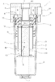
本発明に係る分離器1は、圧縮空気が流れる流路が形成されて圧縮空気から不純物を分離又は除去するためのものである。すなわち分離器1は圧縮空気のための機器である。図1に示すように、分離器1は、内筒2と外筒3とからなる二重管構造を有している。外筒3はヘッド部4とボディ部5とが協働して形成されている。内筒2はヘッド部4とガイド筒6とが協働して形成されている。しがたって、ヘッド部4には内筒2内の空間と連通する貫通孔7と、内筒2と外筒3との間の空間と連通する空洞8とがそれぞれ隔たれて形成されている。
The
外筒3の一方の端部であるヘッド部4側の端面は、貫通孔7が形成された箇所を除いて閉塞されている。この外筒3の一方の端部側の側面、すなわちヘッド部4の側面は開口して空洞8と連通し、流入口9が形成されている。この流入口9は上述した二重管構造のうち、内筒2と外筒3との間に形成された空間である流入流路10と連通している。すなわち、流入流路10は空間8を含み、さらにボディ部5とガイド筒6との間の空間も含んでいる。この流入流路10は、流入口9側を上流側とし、外筒3の他方の端部(ヘッド部4側とは反対側)方向に延びている。
The end surface on the
一方で、ガイド筒6の内側、すなわち流入流路10と内筒2で隔たられた空間は流出流路11として形成されている。すなわち、流出流路11は上述した二重管構造のうち、内筒2の一方の端部(図1の下側)を上流側として他方の端部(図1の上側)方向に延びている。ここで、内筒2の一方の端部はボディ部5、すなわち外筒3内に位置している。内筒2の他方の端部にはヘッド部4が配されていて、上述した貫通孔7を形成するための開口は流出口12として形成されている。換言すれば、流出口12は内筒2の他方の端部に開口して形成されている。
On the other hand, the inside of the
流入流路10及び流出流路11は折り返し流路13にて連通している。具体的には、折り返し流路13は内筒2の一方の端部(ガイド筒6の一方の端部)を外側から内側に回り込む部位に形成されていて、流入流路10の下流側と流出流路11の上流側とをつないでいる。図1の例では内筒2と外筒3とは円筒形状であるため、折り返し流路13は周方向の全て(360°方向)に形成されている。
The
上述した流入流路10には、分離ユニット14が配設されている。この分離ユニット14は、流入口12から流入してくる圧縮空気内の凝縮水たるドレンや塵埃、あるいは空気圧縮機で用いられている潤滑油等の不純物を分離又は除去するためのものである。なお、この例では分離ユニット14が流入流路10に設けられた例を示すが、採用する構造によっては分離ユニット14が折り返し流路13や流出流路11に設けられてもよい。
A
分離ユニット14は、流出流路10内で内筒2の外周に設けられた螺旋状の羽根15を有している。具体的には、分離ユニット14は略筒状(図1の例では円筒形状)の筒体16を有し、この外側に螺旋状に羽根15が形成されている。この螺旋状の羽根15を圧縮空気が通過することで、内筒2の外周を旋回流となって圧縮空気は流通する。筒体16はガイド筒6及び貫通孔7と協働して流出流路11を形成している。外筒3の他方の端部側の端面は貫通して開口し、排出口17が形成されている。この排出口17は、圧縮空気から分離又は除去された不純物を排出するためのものである。
The
以下に分離器1の作用について説明する。エアコンプレッサ等の空気圧縮機から吐出された圧縮空気は、まず流入口9から分離器1内へ流入する(矢印A)。圧縮空気はその後流入流路10内を通り、このとき分離ユニット14の羽根15によって旋回流となる(矢印D)。旋回流となったまま流入流路10を通るうちに、その遠心力によって空気より重い不純物は外側に飛ばされる。このようなサイクロン形式を用いて不純物を分離又は除去することは効率がよい。大部分の不純物はそのままボディ部5の内壁を伝って落下する。そして不純物は排出口17より排出され、適宜ドレントラップ(図2参照)等により回収される。ある程度不純物が分離又は除去された圧縮空気はそのまま折り返し流路13を通り(矢印B)流出流路11へと流れていく(矢印C)。このとき、ガイド筒6のさらに内側には金網等の線状格子体18が配設されている。圧縮空気がこの線状格子体18を通過する際に不純物はここに付着し、さらに分離又は除去される。線状格子体18に付着した不純物は落下して排出口17より排出される。そして不純物がほとんど分離又は除去された圧縮空気は、流出流路11を通って流出口12より流出し、エアタンクやフィルタ、あるいはエアドライヤ等の機器内に流入し、その後空圧機器に利用される。
The operation of the
ここで、流出流路11と流出口12とは一直線状に連通している。すなわち、流出流路11は直線状であり、ガイド筒6と筒体16との接続部は屈曲してなく、筒体16内と貫通孔7も屈曲していない。これらは全て一直線状に連通し、したがって流出流路11はまっすぐに延びてそのまま流出口12とつながっている。このため、圧縮空気の流路が折れ曲がる箇所は、流入口9から流入流路10に向けての部位(矢印A)と、流入流路10から折り返し流路13に向けての部位(矢印B)と、折り返し流路13から流出流路11に向けての部位(矢印C)のみとなる。すなわち、圧縮空気の流路が折れ曲がる箇所は3箇所のみとなる。上述したように、流出流路11と流出口12とは一直線状に連通しているのでこの部位にて流路は折れ曲がらず、従来の分離器に比べて流路が折れ曲がる回数を低減させることができる。このため分離器1単体として圧縮空気に対する圧力損失の抑制を図ることができるので、エネルギー的に効率がよい。また折れ曲がり箇所を低減することは、構造が簡単になるので生産性が向上し、その分製造コストも低減させることができる。また、流出流路11が一直線状に鉛直上方に延びているので、不純物を自重により落下させる距離を長くすることができるので、不純物の分離又は除去効率も向上させることができる。
Here, the
なお、流入口9を外筒3すなわちヘッド部4の側面に複数設けてもよい。空洞8は貫通孔7と隔てられてヘッド部4内の周方向に形成されているので、流入口9はこの空洞8に連通させるように形成すれば複数設けることができる。このようにすることで、圧縮空気が流れる管路からなる圧縮空気圧回路に分離器1を配した際に、種々の管路の形状に適用させることができる。特に多方向から管路が流入してくる部位に配設することができる。例として、ループ管路の途中に配すれば、二方向から流入してくることになる。設けた流入口9が不要な場合は、例えばプラグである蓋19により閉塞すればよい。この蓋19により適宜流入口9の数を選択することができる。
A plurality of
図2に示すように、分離器1を圧縮空気圧回路20に適用すると、分離器1は管路の途中に配設されることになる。図2で示す例は空気圧縮機(エアコンプレッサ)21からエアタンク22までの圧縮空気圧回路20を示している。図2で示すように空気圧縮機21よりもエアタンク22が高い位置にある場合や、空気圧縮機21の吐出口21aよりエアタンク22の導入口22aが高い位置にある場合は、管路が鉛直上方に折れ曲がる部位が必要となる。このような部位である立ち上がり部23に分離器1を配することができる。すなわち、空気圧縮機21からの圧縮空気を流入口9から流入させ(立ち上がり部23の入口側に流入口9が配される)、流出口12から上方向に流出させる(立ち上がり部23の出口側に流出口12が配される)ことで結果的に圧縮空気は管路を鉛直上方に折れ曲がって流通することになる。このようにすれば、分離器1をエルボの代替として用いることができる。このため分離器とエルボとが別々に配されていた従来の圧縮空気圧回路に比してエルボ部分での圧力損失を分離器でカバーすることができる。換言すれば、分離器とエルボが必要であった従来の圧縮空気圧回路に比べ、エルボを不要としてその分の圧力損失を低減できる。さらに当該部分でのエルボの削減は、コスト的な効率も向上させる。なお、上述したように、水分に代表される不純物は排出口17に接続された排出管路(例えばドレン管路)24を通り、ドレントラップ25にて回収される。
As shown in FIG. 2, when the
なお立ち上がり部23において、流入口9に接続された配管である流入管31は、流出口12に接続された配管である流出管32よりもその径が細い。これは流入流路10での旋回流の遠心力を強めて不純物を効率よく除去するため、流入管31の径を細くして流速を速めるためである。また、流出管32の径が太いのは、流速を遅めて自重で不純物を落下させる効率を向上させるためである。
In the rising
圧縮空気圧回路20が図3のような環状のループ部27を含む場合でも分離器1は適用可能である。このようなループ部27は圧縮空気圧回路20の終端に形成されることが多く、ここに例えばエアガン28のような空圧機器が配設される。エアガン28に圧縮空気を導入するために、ループ部27にも立ち上がり部23が形成されている。したがってこの立ち上がり部23にも分離器1は配設可能である。ループ部27の場合、圧縮空気は二方向から流入してくる。このため立ち上がり部23には通常チーズを配設するが、分離器1はこのチーズの代替として用いられる。分離器1の流入口9は、二方向から流入してくるループ部27に配する場合には二つ形成される。ループ部27では高圧側から圧縮空気が流入してくるため、エアガン28が接続される立ち上がり部23に対してどちらから圧縮空気が流れてくるか不明である。このため分離器1とチーズとが別々に配されていた従来のループ部27では立ち上がり部23の両側にそれぞれ分離器を配さなければ分離器1としての意味を奏さなかったが、立ち上がり部23にチーズとして分離器1を設けることができるようになったので、分離器1の配設個数を削減できる。また、チーズと分離器1とを別々に配していた従来の圧縮空気圧回路に比してチーズ部分での圧力損失を分離器でカバーできる。換言すれば、分離器とチーズが必要であった従来のループ部27に比べ、チーズを不要としてその分の圧力損失を低減できる。
The
なお図3の例では、空気圧縮機21よりも上方にループ部27が形成されている例を示し、したがってループ部27に導入するための立ち上がり部23も形成されている回路を示している。また、管路が立ち上がる部位以外で管路が分岐、屈曲している箇所には通常のチーズ29及びエルボ30を用いた例を示している。
3 shows an example in which the
1:分離器、2:内筒、3:外筒、4:ヘッド部、5:ボディ部、6:ガイド筒、7:貫通孔、8:空洞、9:流入口、10:流入流路、11:流出流路、12:流出口、13:折り返し流路、14:分離ユニット、15:羽根、16:筒体、17:排出口、18:線状格子体、19:蓋(プラグ)、20:圧縮空気圧回路、21:空気圧縮機(エアコンプレッサ)、21a:吐出口、22:エアタンク、22a、導入口、22b:吐出口、23:立ち上がり部、24:排出管路、25:ドレントラップ、27:ループ部、28:エアガン、29:チーズ、30:エルボ 1: separator, 2: inner cylinder, 3: outer cylinder, 4: head part, 5: body part, 6: guide cylinder, 7: through hole, 8: cavity, 9: inlet, 10: inflow channel, 11: Outflow channel, 12: Outlet, 13: Folding channel, 14: Separation unit, 15: Blade, 16: Cylindrical body, 17: Discharge port, 18: Linear lattice body, 19: Lid (plug), 20: Compressed pneumatic circuit, 21: Air compressor (air compressor), 21a: Discharge port, 22: Air tank, 22a, introduction port, 22b: Discharge port, 23: Rising part, 24: Discharge pipe, 25: Drain trap 27: Loop part, 28: Air gun, 29: Cheese, 30: Elbow
Claims (4)
前記圧縮空気圧回路の圧力損失低減とチーズの代替とを図る目的で、
前記外筒の一方の端部側の側面に設けられた貫通孔からなる流入口と、
該流入口と連通し且つ前記二重管内を延びる流入流路と、
該流入流路と前記内筒で隔てられ、前記二重管内を延びる流出流路と、
前記流入流路と前記流出流路とを連通する折り返し流路と、
前記外筒を貫通して設けられ、前記不純物が排出される排出口と、
螺旋状の羽根を有すると共に、前記流入流路又は前記折り返し流路又は前記流出流路内に形成され、前記圧縮空気から前記不純物を分離又は除去するための分離ユニットと、
前記流出流路の下流側に開口して形成され、前記流出流路と鉛直一直線状に連通している流出口とを備え、
前記流入口は、チーズの代替とする目的で、前記外筒の水平方向に対向する側面にそれぞれ設けられていることを特徴とする分離器。 Connected to the compressed air circuit, consisting of an inner cylinder and an outer cylinder, at least one end of the inner cylinder having a double pipe disposed in the outer cylinder, forming a flow path through which compressed air flows A separator for separating or removing impurities such as condensed water, dust and oil from the compressed air,
In order to achieve alternative and pressure loss reduction and cheese of the compressed air circuit,
An inflow port formed of a through hole provided on a side surface on one end side of the outer cylinder;
An inflow channel communicating with the inflow port and extending through the double pipe;
An outflow channel that is separated from the inflow channel by the inner cylinder and extends through the double pipe;
A folded channel that communicates the inflow channel and the outflow channel;
An exhaust port provided through the outer cylinder and from which the impurities are discharged;
A separation unit having a spiral blade and formed in the inflow channel or the return channel or the outflow channel, for separating or removing the impurities from the compressed air;
An outlet opening formed on the downstream side of the outflow channel, and in communication with the outflow channel in a straight line,
The said inlet is provided in the side which opposes the horizontal direction of the said outer cylinder, respectively in order to substitute for cheese, The separator characterized by the above-mentioned .
前記折り返し流路は、前記流入流路の下流側と前記内筒の一方の端部とを連通し、
前記流出流路は、前記折り返し流路と連通し且つ前記内筒内を前記内筒の他方の端部方向に延び、
前記流出口は、前記内筒の他方の端部に開口して形成され、
前記排出口は、前記外筒の他方の端部に開口して形成され、
前記分離ユニットは、前記流入流路に配置されて前記圧縮空気を前記流入流路内で旋回流とさせることを特徴とする請求項1に記載の分離器。 An inflow channel is formed between the inner cylinder and the outer cylinder and extends in the direction of the other end of the outer cylinder,
The folded channel communicates the downstream side of the inflow channel and one end of the inner cylinder,
The outflow channel communicates with the folded channel and extends in the inner cylinder toward the other end of the inner cylinder;
The outlet is formed to open at the other end of the inner cylinder,
The discharge port is formed to open at the other end of the outer cylinder,
2. The separator according to claim 1, wherein the separation unit is disposed in the inflow channel and causes the compressed air to swirl in the inflow channel.
前記管路が鉛直上方に折れ曲がる部位の入口側に前記流入口が、出口側に前記流出口が配されていることを特徴とする請求項1又は2に記載の分離器を用いた圧縮空気圧回路。 A compressed pneumatic circuit having a conduit through which compressed air discharged from an air compressor for compressing air flows,
The compressed pneumatic circuit using a separator according to claim 1 or 2, wherein the inlet is disposed on an inlet side of the portion where the pipe is bent vertically upward, and the outlet is disposed on an outlet side. .
前記管路は環状に形成されたループ部を有し、
前記ループ部が鉛直上方に折れ曲がる部位の入口側に前記流入口が、出口側に前記流出口が配されていることを特徴とする請求項1又は2に記載の分離器を用いた圧縮空気圧回路。 A compressed pneumatic circuit having a conduit through which compressed air discharged from an air compressor for compressing air flows,
The pipe has a loop portion formed in an annular shape,
The compressed pneumatic circuit using the separator according to claim 1 or 2, wherein the inflow port is disposed on an inlet side of the portion where the loop portion is bent vertically upward, and the outflow port is disposed on an outlet side. .
Priority Applications (1)
| Application Number | Priority Date | Filing Date | Title |
|---|---|---|---|
| JP2014190858A JP5838457B1 (en) | 2014-09-19 | 2014-09-19 | Separator and compressed air circuit using the same |
Applications Claiming Priority (1)
| Application Number | Priority Date | Filing Date | Title |
|---|---|---|---|
| JP2014190858A JP5838457B1 (en) | 2014-09-19 | 2014-09-19 | Separator and compressed air circuit using the same |
Publications (2)
| Publication Number | Publication Date |
|---|---|
| JP5838457B1 true JP5838457B1 (en) | 2016-01-06 |
| JP2016059887A JP2016059887A (en) | 2016-04-25 |
Family
ID=55069237
Family Applications (1)
| Application Number | Title | Priority Date | Filing Date |
|---|---|---|---|
| JP2014190858A Active JP5838457B1 (en) | 2014-09-19 | 2014-09-19 | Separator and compressed air circuit using the same |
Country Status (1)
| Country | Link |
|---|---|
| JP (1) | JP5838457B1 (en) |
Families Citing this family (2)
| Publication number | Priority date | Publication date | Assignee | Title |
|---|---|---|---|---|
| JP7392949B2 (en) * | 2020-12-14 | 2023-12-06 | 株式会社フクハラ | Separator and compressed air pressure circuit using it |
| JP7289461B2 (en) * | 2021-07-21 | 2023-06-12 | 株式会社フクハラ | Separator and compressed gas pressure circuit |
Citations (12)
| Publication number | Priority date | Publication date | Assignee | Title |
|---|---|---|---|---|
| JPS50118373A (en) * | 1974-01-16 | 1975-09-17 | ||
| JPS61181514A (en) * | 1984-11-23 | 1986-08-14 | ドムニック ハンター リミテッド | Apparatus for removing carrier liquid from gas stream |
| JPS63164926U (en) * | 1987-04-17 | 1988-10-27 | ||
| US5240115A (en) * | 1992-11-10 | 1993-08-31 | Beloit Technologies, Inc. | Field adjustable hydrocyclone |
| JPH05312438A (en) * | 1992-03-09 | 1993-11-22 | Daikin Ind Ltd | Centrifugal oil separator |
| JPH07180694A (en) * | 1993-12-24 | 1995-07-18 | Kobe Steel Ltd | Supply pressure control method of industrial air |
| JP2001246216A (en) * | 1999-12-28 | 2001-09-11 | Denso Corp | Gas-liquid separation device |
| JP2011183278A (en) * | 2010-03-05 | 2011-09-22 | Japan Oil Gas & Metals National Corp | Gas-liquid separator and flow rate measurement device |
| JP2011526539A (en) * | 2008-06-30 | 2011-10-13 | ペトロレオ ブラジレイロ ソシエダ アノニマ − ペトロブラス | Cyclone separator with two gas outlets and separation method |
| US20120097616A1 (en) * | 2009-07-03 | 2012-04-26 | Jan Backman | Hydrocyclone, system and method for cleaning cellulose suspensions |
| JP2013128894A (en) * | 2011-12-22 | 2013-07-04 | Tlv Co Ltd | Gas-liquid separator |
| JP2013148308A (en) * | 2012-01-23 | 2013-08-01 | Hitachi Appliances Inc | Oil separator |
-
2014
- 2014-09-19 JP JP2014190858A patent/JP5838457B1/en active Active
Patent Citations (12)
| Publication number | Priority date | Publication date | Assignee | Title |
|---|---|---|---|---|
| JPS50118373A (en) * | 1974-01-16 | 1975-09-17 | ||
| JPS61181514A (en) * | 1984-11-23 | 1986-08-14 | ドムニック ハンター リミテッド | Apparatus for removing carrier liquid from gas stream |
| JPS63164926U (en) * | 1987-04-17 | 1988-10-27 | ||
| JPH05312438A (en) * | 1992-03-09 | 1993-11-22 | Daikin Ind Ltd | Centrifugal oil separator |
| US5240115A (en) * | 1992-11-10 | 1993-08-31 | Beloit Technologies, Inc. | Field adjustable hydrocyclone |
| JPH07180694A (en) * | 1993-12-24 | 1995-07-18 | Kobe Steel Ltd | Supply pressure control method of industrial air |
| JP2001246216A (en) * | 1999-12-28 | 2001-09-11 | Denso Corp | Gas-liquid separation device |
| JP2011526539A (en) * | 2008-06-30 | 2011-10-13 | ペトロレオ ブラジレイロ ソシエダ アノニマ − ペトロブラス | Cyclone separator with two gas outlets and separation method |
| US20120097616A1 (en) * | 2009-07-03 | 2012-04-26 | Jan Backman | Hydrocyclone, system and method for cleaning cellulose suspensions |
| JP2011183278A (en) * | 2010-03-05 | 2011-09-22 | Japan Oil Gas & Metals National Corp | Gas-liquid separator and flow rate measurement device |
| JP2013128894A (en) * | 2011-12-22 | 2013-07-04 | Tlv Co Ltd | Gas-liquid separator |
| JP2013148308A (en) * | 2012-01-23 | 2013-08-01 | Hitachi Appliances Inc | Oil separator |
Also Published As
| Publication number | Publication date |
|---|---|
| JP2016059887A (en) | 2016-04-25 |
Similar Documents
| Publication | Publication Date | Title |
|---|---|---|
| CN103054520B (en) | Multi-stage cyclone separator for dust collector | |
| JP2015144824A (en) | Vacuum cleaner separation device | |
| JP6066136B2 (en) | Vacuum cleaner separation device | |
| CN110787597A (en) | Gas-liquid separation equipment | |
| US10710013B2 (en) | Compact axial flow separator | |
| JP5720027B1 (en) | Air filter and compressed pneumatic circuit using the same | |
| CN207347532U (en) | A kind of gas and water separator | |
| CN104697255A (en) | Separator device for separating lubricating oil and in refrigerating system and method for oil separating | |
| CN105073221B (en) | Gas desander | |
| JP5838457B1 (en) | Separator and compressed air circuit using the same | |
| CN208694580U (en) | A kind of gas and oil separating plant for air compressor | |
| US20080264009A1 (en) | Cyclone Collector | |
| CN110006195A (en) | Filter type oil separator | |
| CN204478608U (en) | Helical oil separator | |
| US2659451A (en) | Centrifugal gas cleaner | |
| CN202885380U (en) | Spiral type oil separator | |
| CN206229075U (en) | Gas-liquid separator | |
| CN104368225A (en) | Steam-water separator for air compressor | |
| CN103736331A (en) | Foam metal filtering type oil separator | |
| CN102294200B (en) | Multi-opening released steam explosion device | |
| CN112221255A (en) | Multistage steam-water separator arranged in parallel | |
| CN206444360U (en) | A kind of oil removal filter | |
| CN100420416C (en) | Multiple air inlet separation device and dust cup device containing the device | |
| CN207056138U (en) | Cyclone combined separating device for smoke dust | |
| JP2019136621A (en) | Drain treatment structure |
Legal Events
| Date | Code | Title | Description |
|---|---|---|---|
| TRDD | Decision of grant or rejection written | ||
| A01 | Written decision to grant a patent or to grant a registration (utility model) |
Free format text: JAPANESE INTERMEDIATE CODE: A01 Effective date: 20151006 |
|
| A61 | First payment of annual fees (during grant procedure) |
Free format text: JAPANESE INTERMEDIATE CODE: A61 Effective date: 20151009 |
|
| R150 | Certificate of patent or registration of utility model |
Ref document number: 5838457 Country of ref document: JP Free format text: JAPANESE INTERMEDIATE CODE: R150 |
|
| R250 | Receipt of annual fees |
Free format text: JAPANESE INTERMEDIATE CODE: R250 |
|
| R250 | Receipt of annual fees |
Free format text: JAPANESE INTERMEDIATE CODE: R250 |
|
| R250 | Receipt of annual fees |
Free format text: JAPANESE INTERMEDIATE CODE: R250 |
|
| R250 | Receipt of annual fees |
Free format text: JAPANESE INTERMEDIATE CODE: R250 |
|
| R250 | Receipt of annual fees |
Free format text: JAPANESE INTERMEDIATE CODE: R250 |
|
| R250 | Receipt of annual fees |
Free format text: JAPANESE INTERMEDIATE CODE: R250 |
|
| R250 | Receipt of annual fees |
Free format text: JAPANESE INTERMEDIATE CODE: R250 |